
Digital-Twin-Enabled Process Monitoring for a Robotic Additive Manufacturing Cell Using Wire-Based Laser Metal Deposition


Abstract

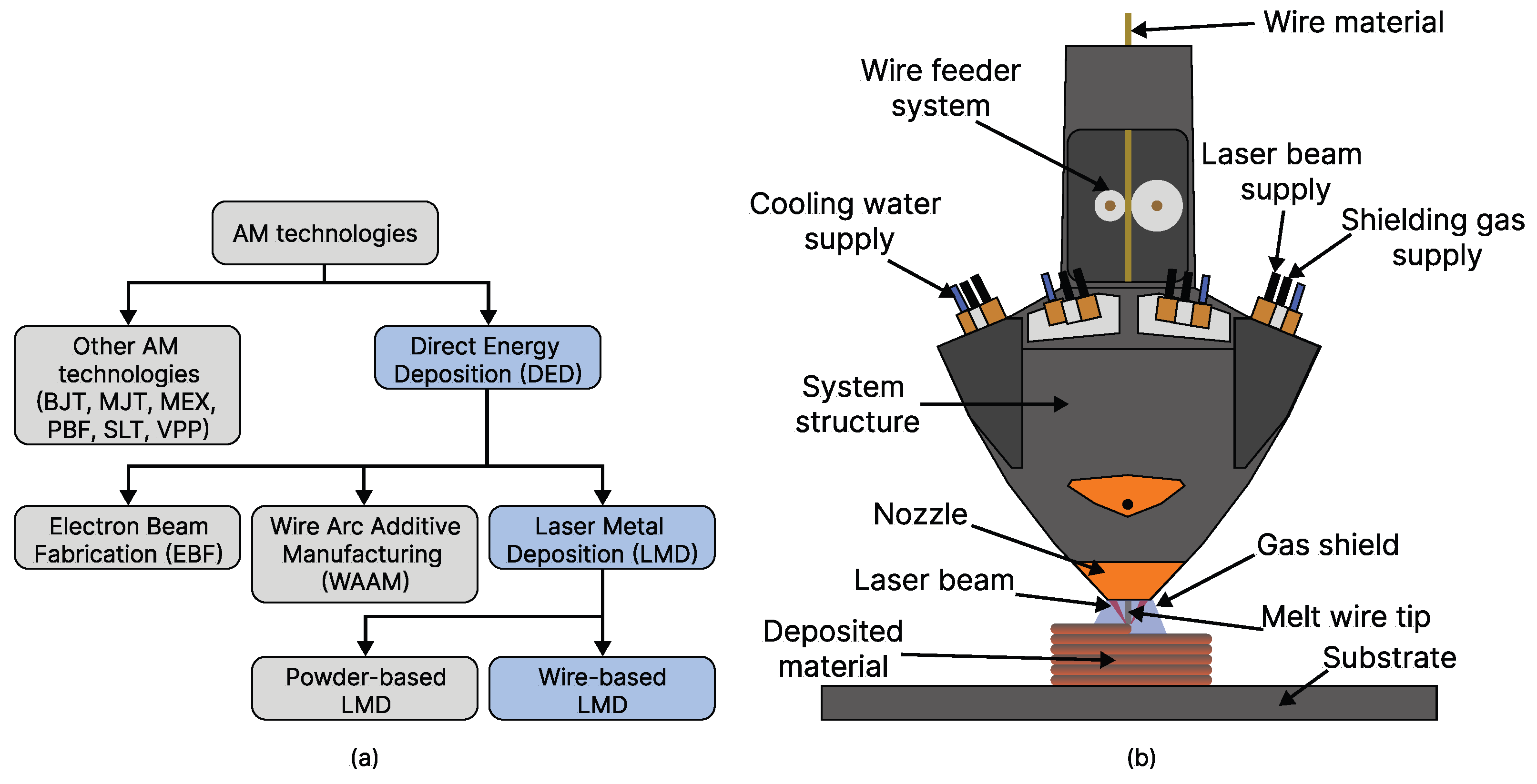
1. Introduction
2. Literature Background
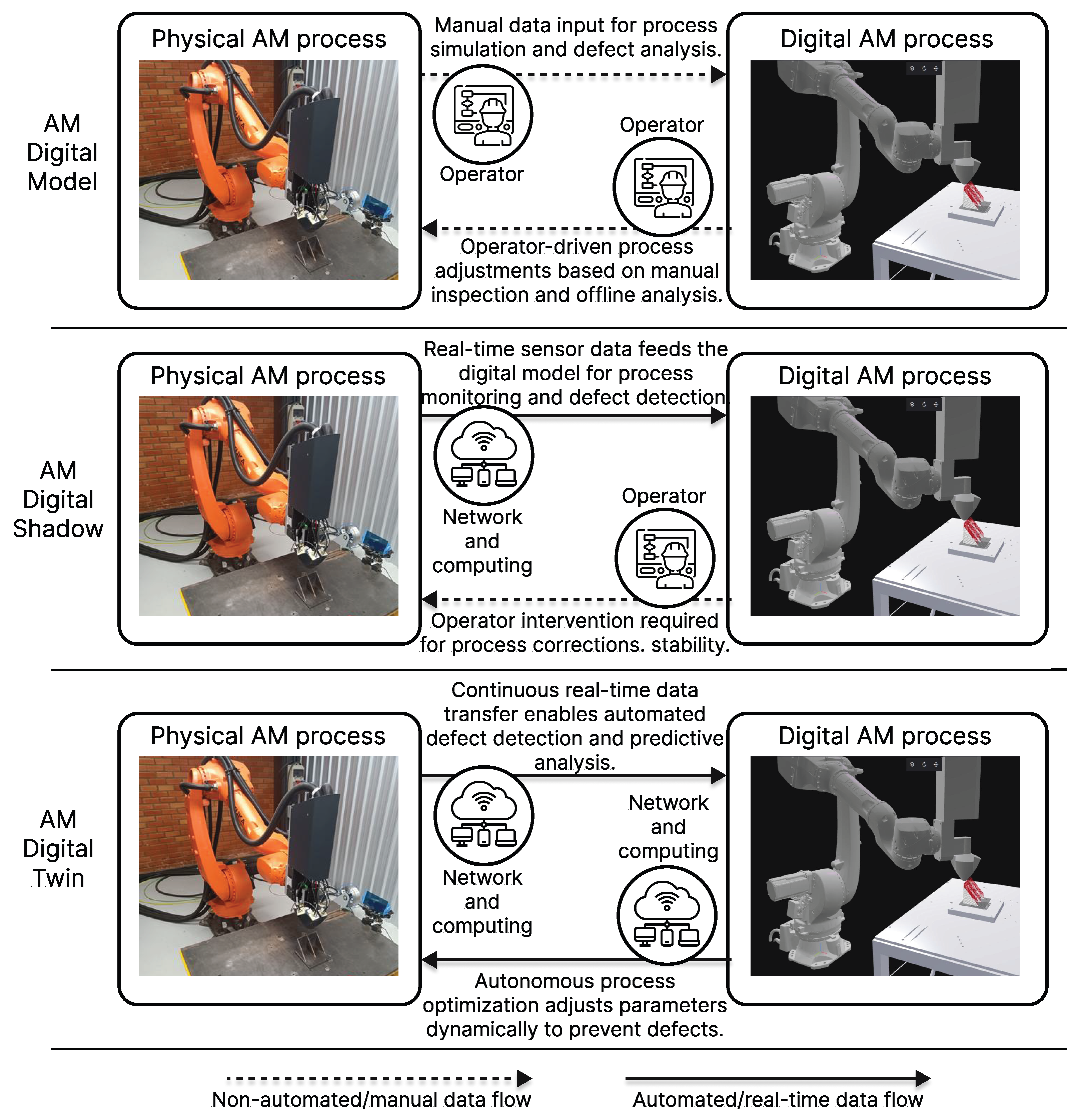
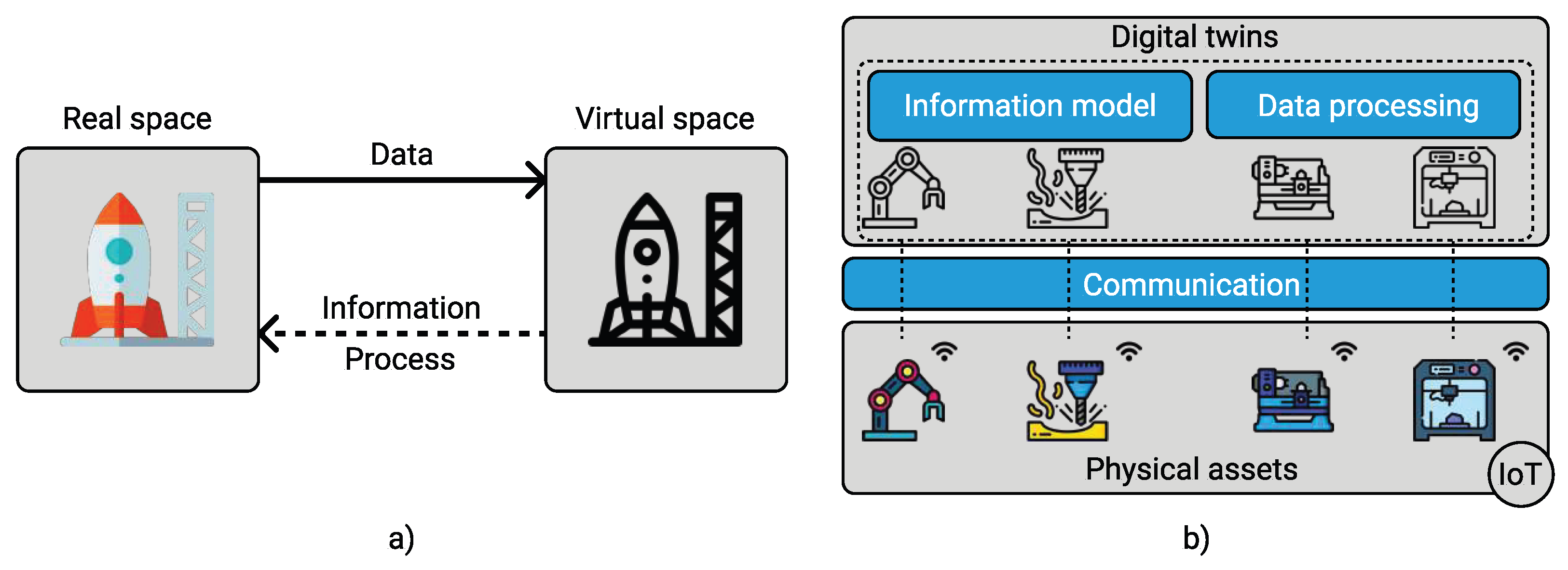
2.1. The Concept of DTs
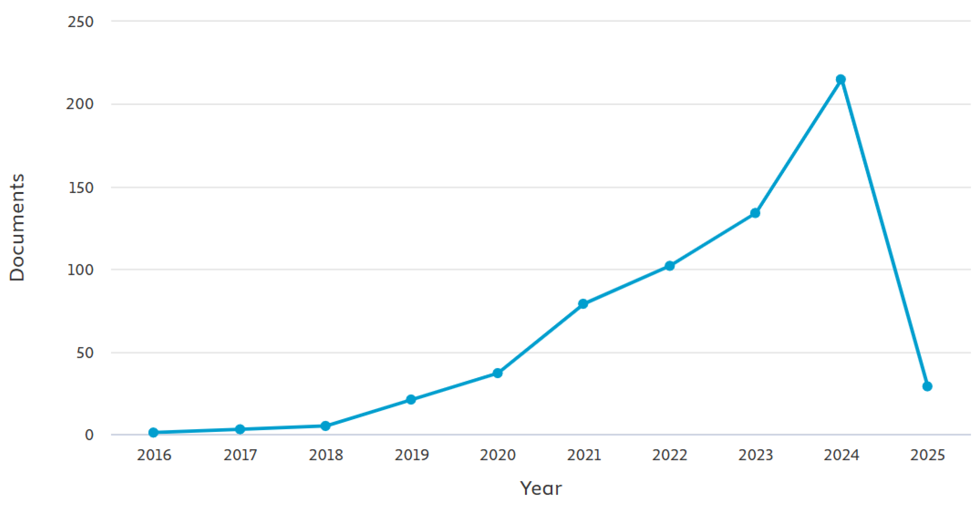
2.2. Research on DT Applications in AM
DTs for Process Monitoring and Defect Detection in Metal AM
3. Reference Models of DTs for Manufacturing
3.1. Three-Dimensional Models
3.2. Five-Dimensional Model
3.3. Digital Twin Framework for Machining
3.4. Other Related Proposals
3.5. ISO 23247—DT Reference Framework for Manufacturing
- Part 1—Overview and general principles [15]: Provide an overview of the general principles of DTs, as well as definitions, requirements, and development guidance;
- Part 2—Reference architecture [16]: Provides an architecture reference model for a manufacturing DT framework;
- Part 3—Digital representation of manufacturing elements [17]: Helps to identify the physical elements that need to be mapped to the digital model;
- Part 4—Information exchange [18]: Establishes the requirements for the proper synchronization and exchange of data throughout the DT framework;
- Part 5 (Currently in a draft version under development)—Digital threads for digital twins [19]: Describes how digital threads facilitate the creation, connectivity, management, and maintenance of manufacturing DTs throughout the product lifecycle by outlining principles, demonstrating methodologies, and providing case studies.
3.6. Research on the ISO 23247 Framework
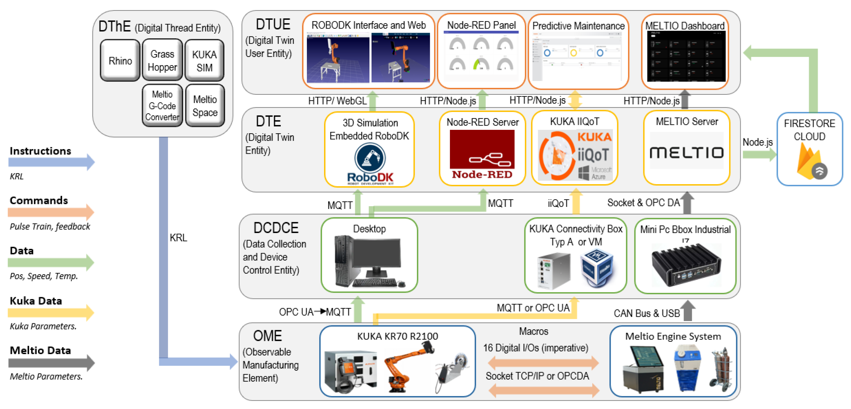
4. Overview of the ISO-23247-Based Framework for the Robotic AM Cell
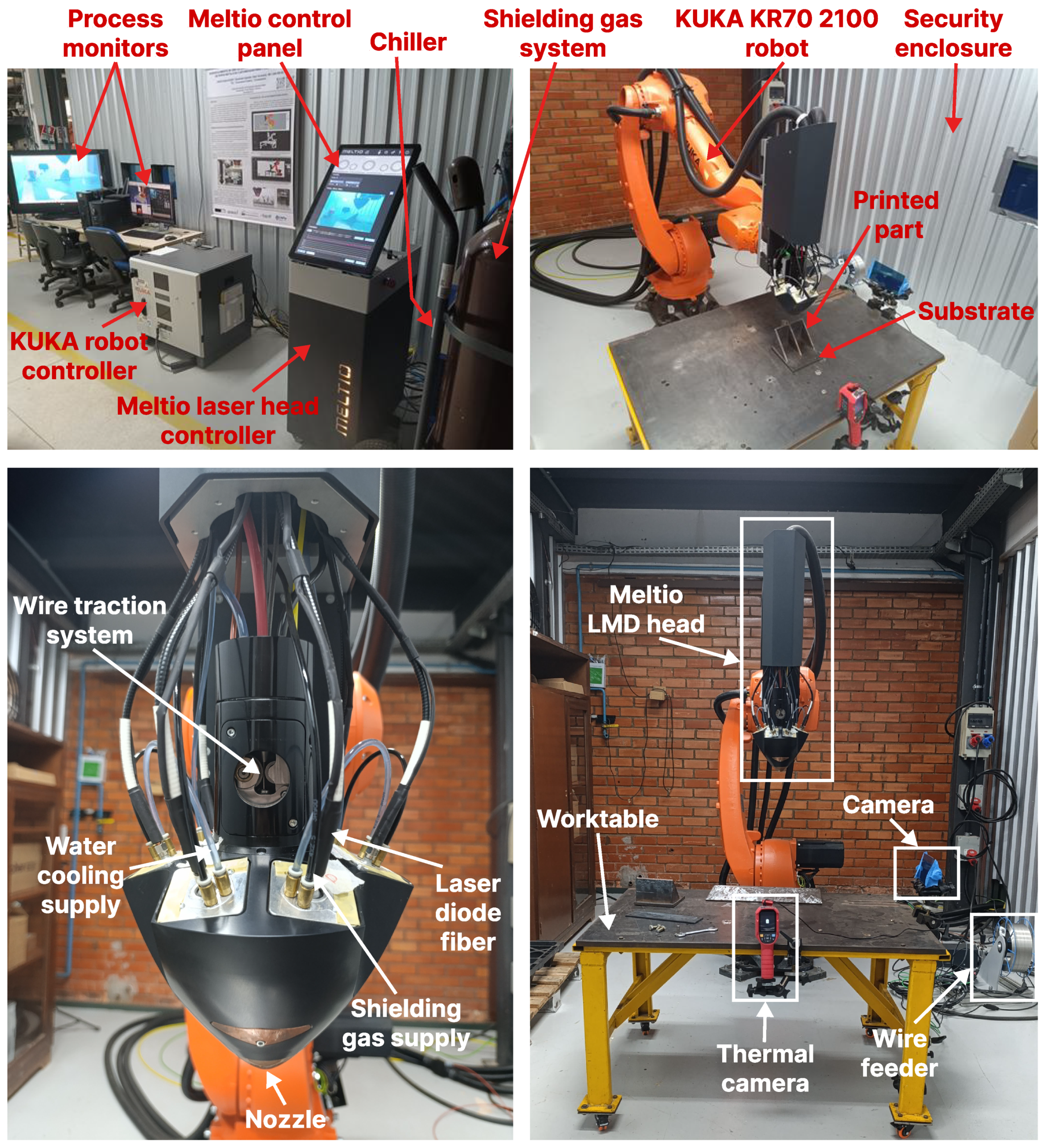
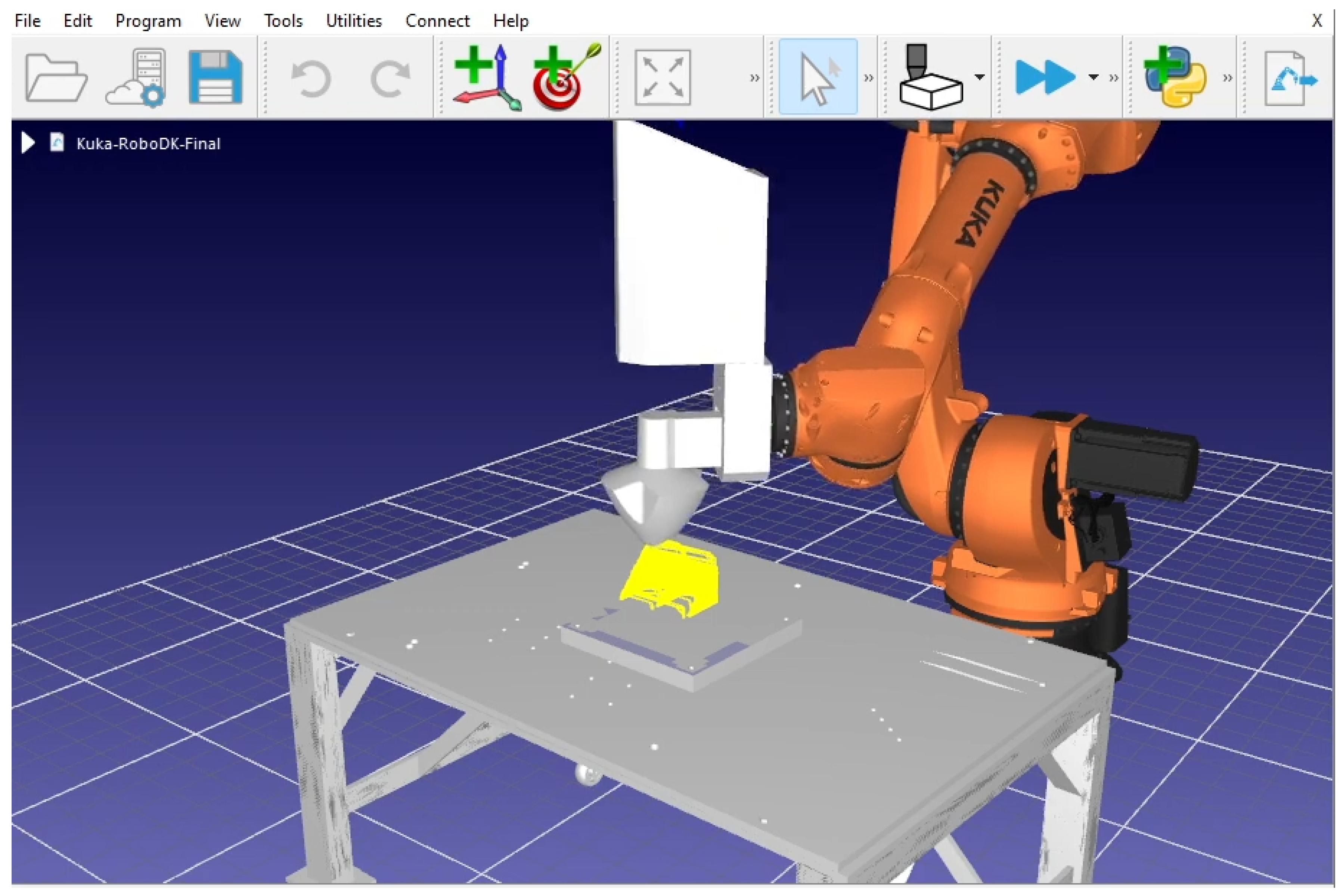
4.1. Setup of the Robotic LMD AM Cell
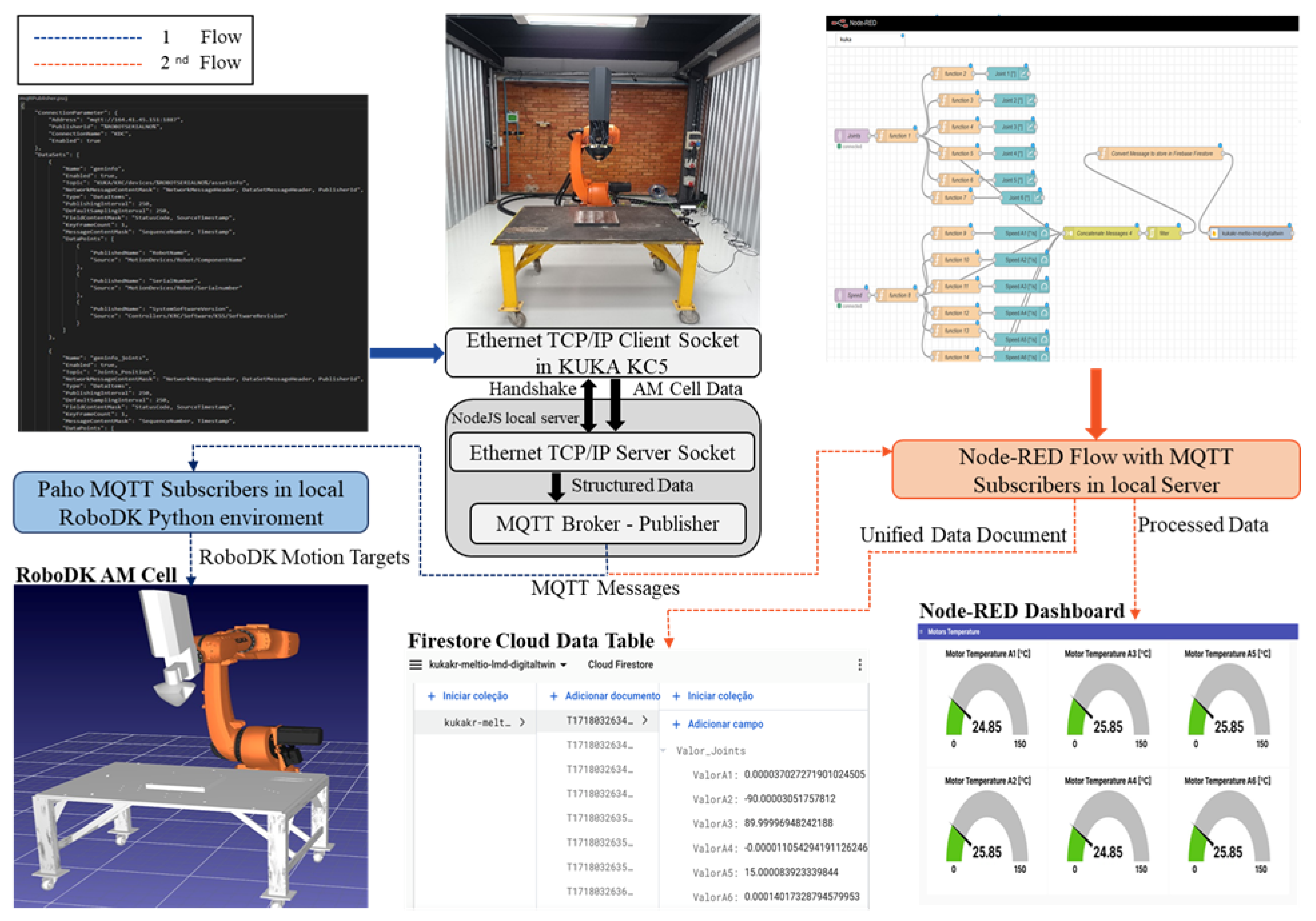
4.2. Description of the DThE and DCDCE Domains
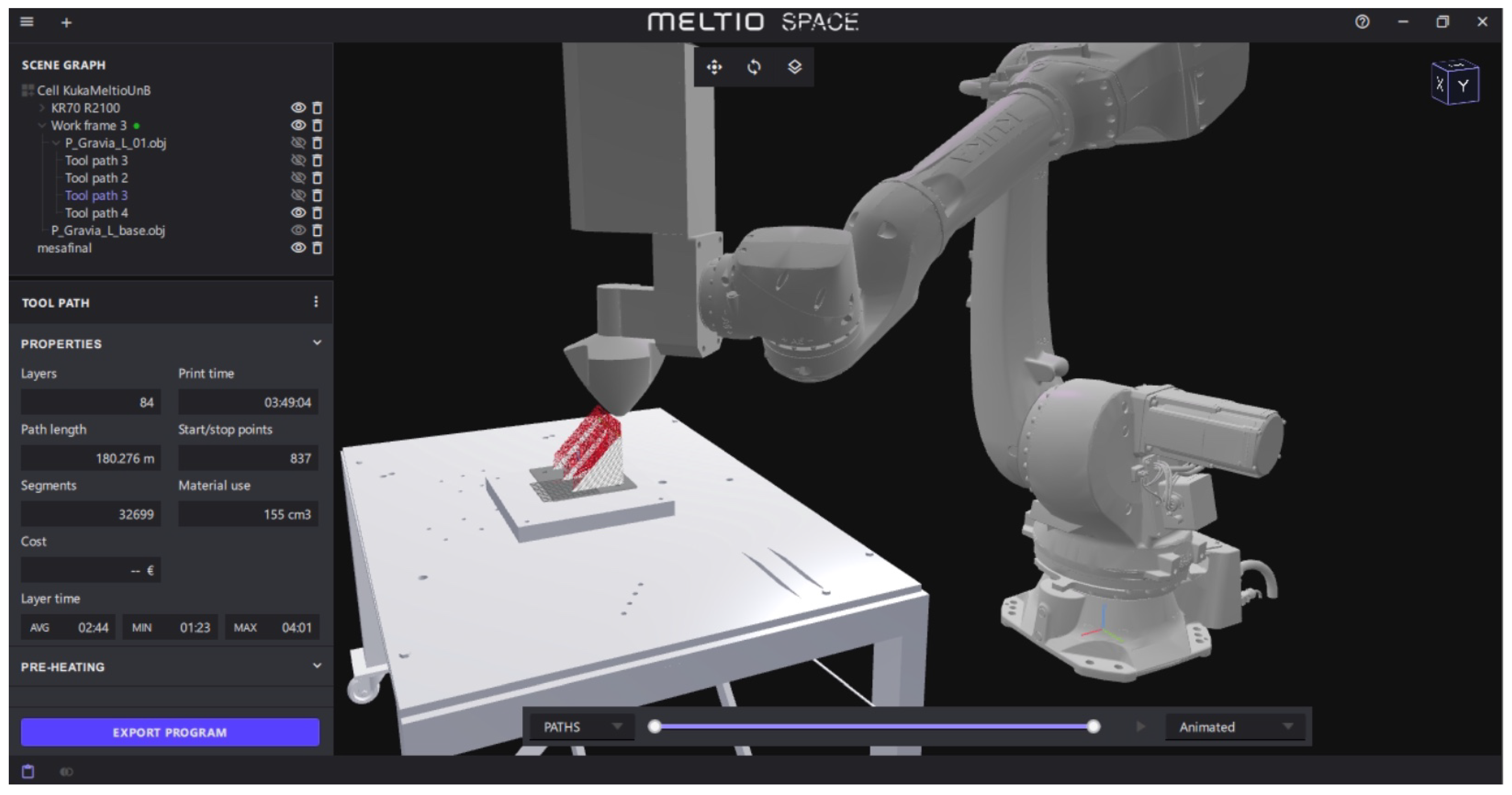
4.3. Implementation of DTs in the Robotic LMD Cell
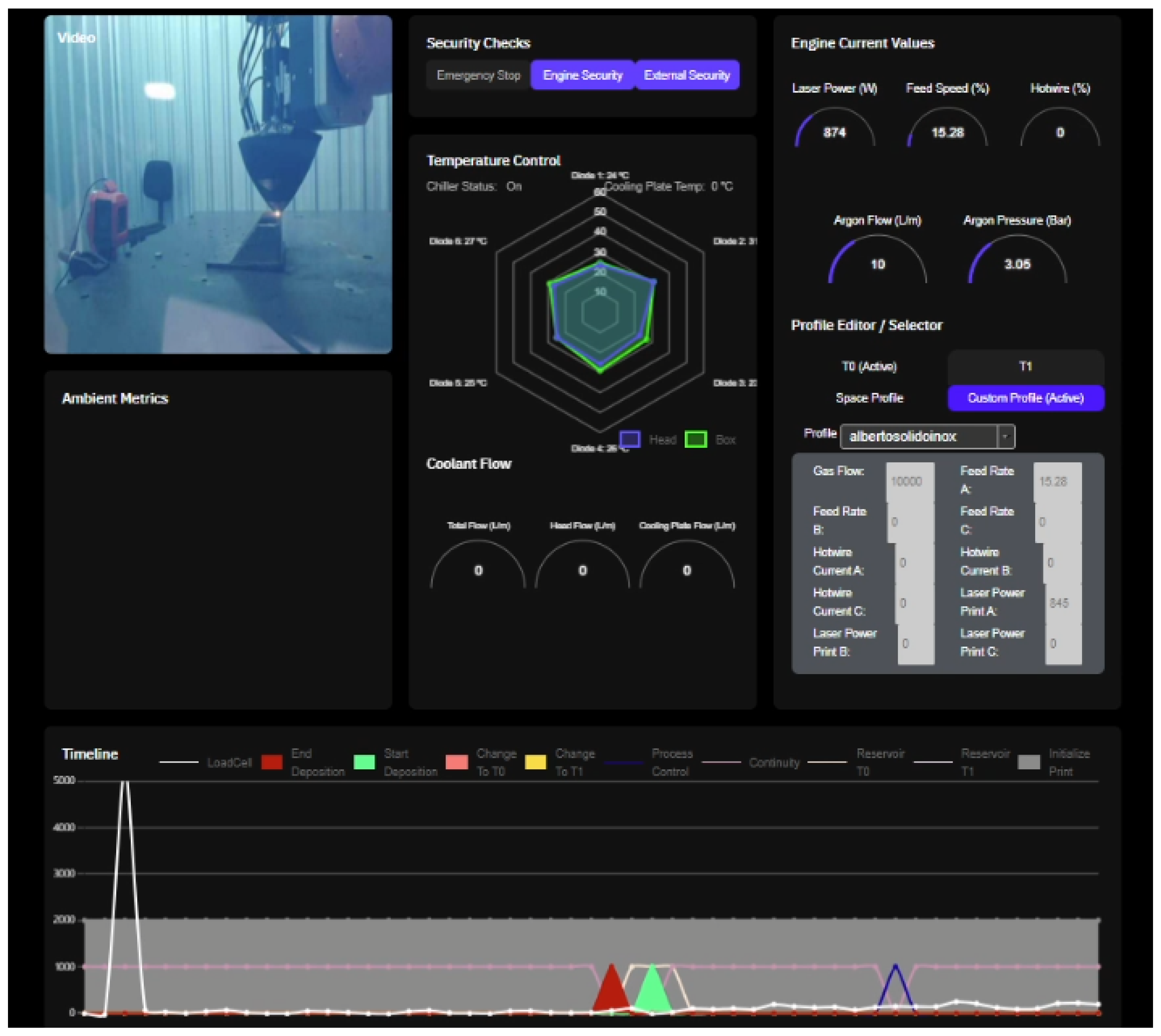
5. Prescriptive Analysis of Data Stored in Firebase and Meltio Engine
- Balling Defects: Occur when the material melts before making contact with the build plate, forming a bright, spherical bead in mid-air because of the incorrect laser alignment;
- Dripping Defects: Arise when the wire momentarily loses contact with the build plate, leading to incomplete fusion. Minor cases may be tolerable, but pronounced dripping can disrupt subsequent layers;
- Necking Defects: Manifest as a thinning melt pool before detaching from the wire. This indicates insufficient material, leading to weak inter-layer adhesion and wavy surface defects;
- Overbuilding Defects: The opposite of necking, where excessive material deposition results in a gradual increase in the layer height beyond the specified parameters, disrupting the uniformity;
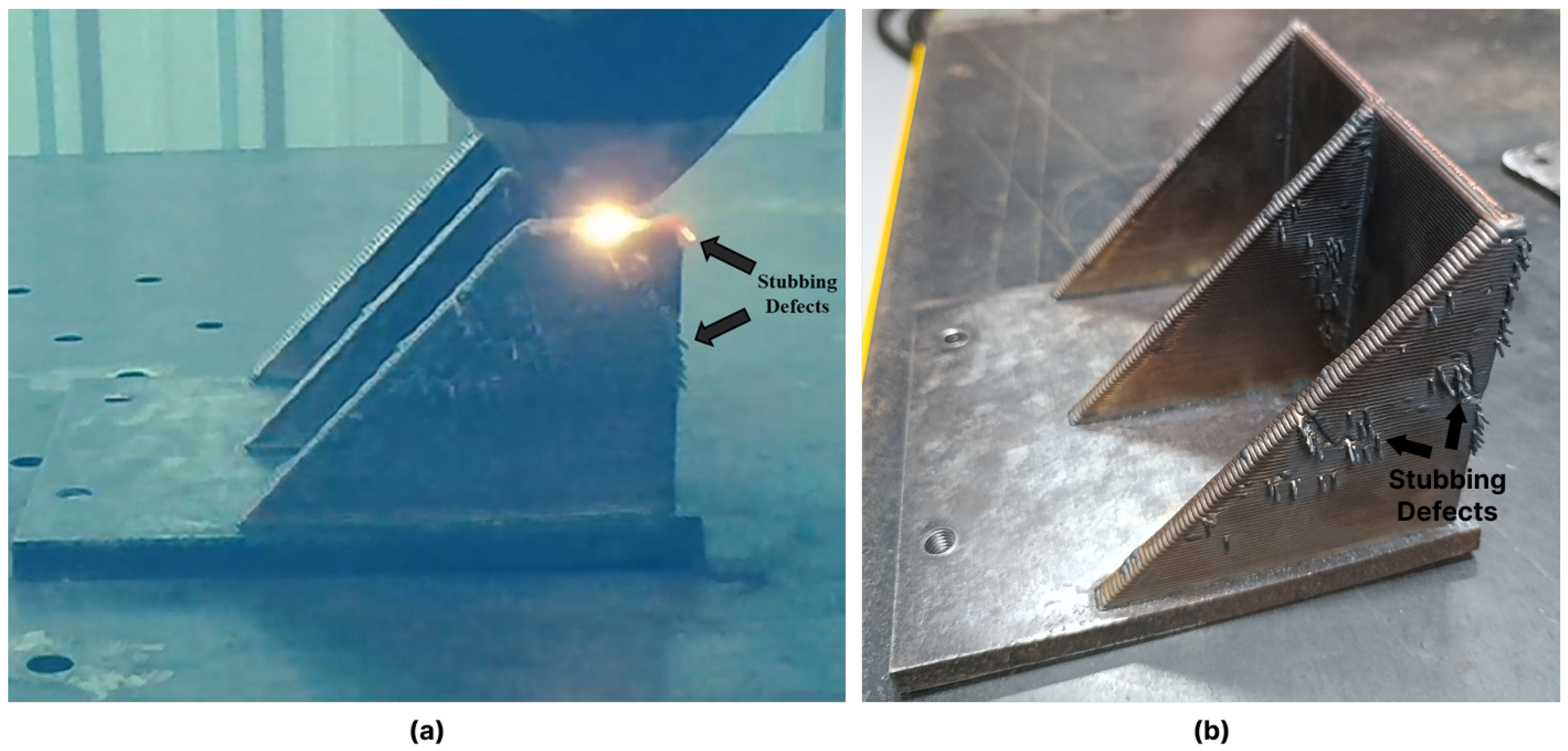
- Stubbing Defects: Occur when insufficient energy reaches the wire, preventing proper melting and leading to excessive force on the Meltio head. This can result in severe process failure and potential machine damage (Figure 20).
6. Contributions of This Work
- Standardized Framework: The DT architecture aligns with ISO 23247, ensuring structured integration between digital and physical systems. This adherence to standards facilitates scalability and interoperability in industrial environments;
- Interdisciplinary Approach: By integrating concepts from mechanical engineering, robotics, and computer science, this work establishes a solid foundation for future research and technological advancements in AM;
- Validation in a Real-World Environment: The proposed architecture has been implemented and tested in an operational setting, demonstrating its feasibility and potential for broader adoption in advanced manufacturing;
- Enhanced Decision Making with Real-Time Data: The DT system enables dynamic simulations, real-time monitoring, and predictive analytics, improving the process adaptability and reducing production inefficiencies;
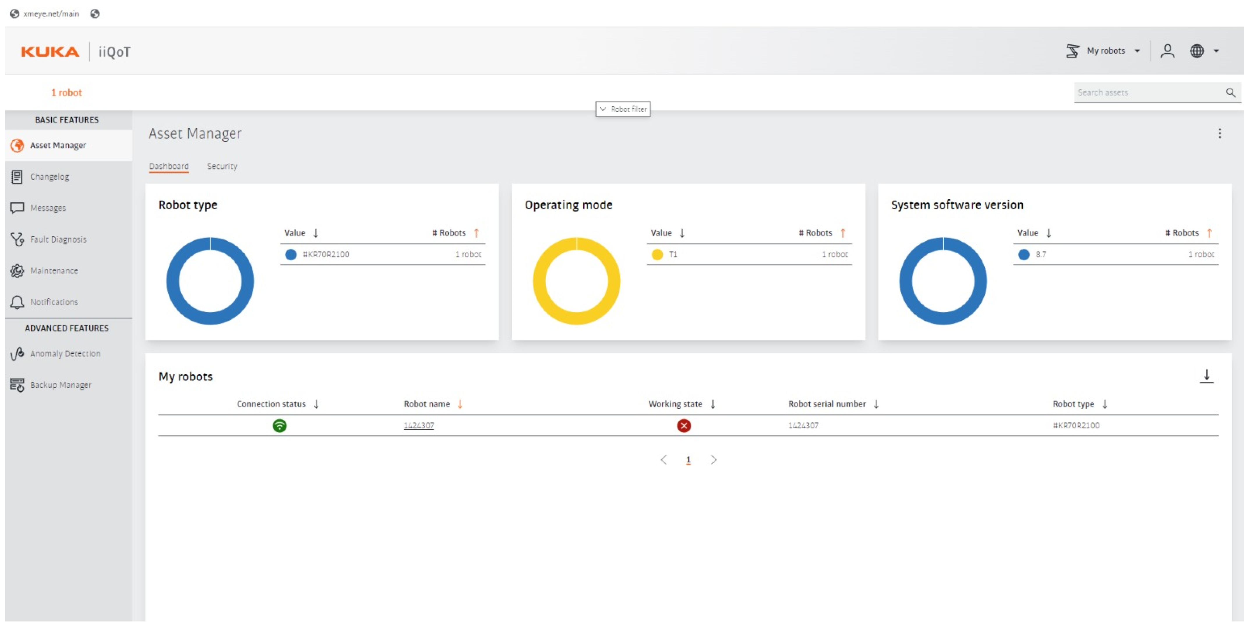
- Predictive Maintenance Capabilities: The integration of KUKA iiQoT with the Meltio dashboard facilitates continuous monitoring and data-informed maintenance strategies, contributing to failure reduction and improved equipment lifespans;
- Advanced Technology Integration: This research leverages CAD/CAPP/CAM, RoboDK, Node-RED, and FireStore Cloud for seamless process monitoring, data management, and quality control, ensuring a fully integrated manufacturing ecosystem;
- Contributions to Industry 4.0 and 5.0: This work demonstrates how digitalization, automation, and cyber–physical integration enhance efficiency, flexibility, and customization, aligning with the principles of Industry 4.0 while also considering the human-centric, sustainable, and resilient focus of Industry 5.0 for the next generation of manufacturing systems.
7. Conclusions
Author Contributions
Funding
Data Availability Statement
Acknowledgments
Conflicts of Interest
References
- Tao, F.; Qi, Q. New IT Driven Service-Oriented Smart Manufacturing: Framework and Characteristics. IEEE Trans. Syst. Man Cybern. Syst. 2019, 49, 81–91. [Google Scholar] [CrossRef]
- Kagermann, H.; Helbig, J.; Hellinger, A.; Wahlster, W. Securing the future of German manufacturing Industry—Recommendations for Implementing the Strategic Initiative INDUSTRIE 4.0—Final Report of the Industrie 4.0 Working Group. Forschungsunion-Acatech Natl. Acad. Sci. Eng. 2013. Available online: https://www.din.de/resource/blob/76902/e8cac883f42bf28536e7e8165993f1fd/recommendations-for-implementing-industry-4-0-data.pdf (accessed on 16 March 2025).
- Monostori, L. Cyber-physical Production Systems: Roots, Expectations and R&D Challenges. Procedia CIRP 2014, 17, 9–13. [Google Scholar] [CrossRef]
- Xu, X.; Lu, Y.; Vogel-Heuser, B.; Wang, L. Industry 4.0 and Industry 5.0—Inception, conception and perception. J. Manuf. Syst. 2021, 61, 530–535. [Google Scholar] [CrossRef]
- Lu, Y.; Liu, C.; Wang, K.I.K.; Huang, H.; Xu, X. Digital Twin-driven smart manufacturing: Connotation, reference model, applications and research issues. Robot. Comput.-Integr. Manuf. 2020, 61, 101837. [Google Scholar] [CrossRef]
- Ciano, M.P.; Pozzi, R.; Rossi, T.; Strozzi, F. Digital twin-enabled smart industrial systems: A bibliometric review. Int. J. Comput. Integr. Manuf. 2021, 34, 690–708. [Google Scholar] [CrossRef]
- Heindl, W.; Stary, C. Structured Development of Digital Twins—A Cross-Domain Analysis towards a Unified Approach. Processes 2022, 10, 1490. [Google Scholar] [CrossRef]
- Cimino, C.; Negri, E.; Fumagalli, L. Review of digital twin applications in manufacturing. Comput. Ind. 2019, 113, 103130. [Google Scholar] [CrossRef]
- Frazier, W.E. Metal Additive Manufacturing: A Review. J. Mater. Eng. Perform. 2014, 23, 1917–1928. [Google Scholar] [CrossRef]
- ISO/ASTM 52900; Additive Manufacturing—General Principles—Fundamentals and Vocabulary. International Standard Organization: London, UK, 2021.
- Guerra, M.G.; Lavecchia, F. Measurement of additively manufactured freeform artefacts: The influence of surface texture on measurements carried out with optical techniques. Measurement 2023, 209, 112540. [Google Scholar] [CrossRef]
- Yan, L.; Chen, Y.; Liou, F. Additive manufacturing of functionally graded metallic materials using laser metal deposition. Addit. Manuf. 2020, 31, 100901. [Google Scholar] [CrossRef]
- Alvares, A.J.; Lacroix, I.; de Lima Maron, M.A.; Figueroa, B.S. Desenvolvimento de uma célula de manufatura aditiva robotizada baseada no processo deposição de metal à laser usando arame de soldagem. Peer Rev. 2023, 5, 17–39. [Google Scholar] [CrossRef]
- Garmendia, I.; Pujana, J.; Lamikiz, A.; Madarieta, M.; Leunda, J. Structured light-based height control for laser metal deposition. J. Manuf. Process. 2019, 42, 20–27. [Google Scholar] [CrossRef]
- 23247-1, I; Automation Systems and Integration—Digital Twin Framework for Manufacturing—Part 1: Overview and General Principles. International Standard Organization: London, UK, 2021.
- ISO 23247-2; Automation Systems and Integration—Digital Twin Framework for Manufacturing—Part 2: Reference Architecture. International Standard Organization: London, UK, 2021.
- ISO 23247-3; Automation Systems and Integration—Digital Twin Framework for Manufacturing—Part 3: Digital Representation of Manufacturing Elements. International Standard Organization: London, UK, 2021.
- ISO 23247-4; Automation Systems and Integration—Digital Twin Framework for Manufacturing—Part 4: Information Exchange. International Standard Organization: London, UK, 2021.
- ISO 23247-5; Automation Systems and Integration—Digital Twin Framework for Manufacturing—Part 5: Digital Thread for Digital Twin. International Standard Organization: London, UK, 2024.
- Grieves, M. Digital Twin: Manufacturing Excellence through Virtual Factory Replication. White Pap. 2014, 1, 1–7. [Google Scholar]
- Glaessgen, E.H.; Stargel, D.S. The Digital Twin Paradigm for Future NASA and U.S. Air Force Vehicles. In Proceedings of the 53rd AIAA/ASME/ASCE/AHS/ASC Structures, Structural Dynamics and Materials Conference 20th AIAA/ASME/AHS Adaptive Structures Conference 14th AIAA, Honolulu, HI, USA, 23–26 April 2012; p. 1818. [Google Scholar]
- Tao, F.; Zhang, H.; Liu, A.; Nee, A.Y.C. Digital Twin in Industry: State-of-the-Art. IEEE Trans. Ind. Inform. 2019, 15, 2405–2415. [Google Scholar] [CrossRef]
- Barricelli, B.R.; Casiraghi, E.; Fogli, D. A Survey on Digital Twin: Definitions, Characteristics, Applications, and Design Implications. IEEE Access 2019, 7, 167653–167671. [Google Scholar] [CrossRef]
- Tao, F.; Qi, Q.; Wang, L.; Nee, A. Digital Twins and Cyber–Physical Systems toward Smart Manufacturing and Industry 4.0: Correlation and Comparison. Engineering 2019, 5, 653–661. [Google Scholar] [CrossRef]
- Kritzinger, W.; Karner, M.; Traar, G.; Henjes, J.; Sihn, W. Digital Twin in manufacturing: A categorical literature review and classification. IFAC-PapersOnLine 2018, 51, 1016–1022. [Google Scholar] [CrossRef]
- Chen, Z.; Surendraarcharyagie, K.; Granland, K.; Chen, C.; Xu, X.; Xiong, Y.; Davies, C.; Tang, Y. Service oriented digital twin for additive manufacturing process. J. Manuf. Syst. 2024, 74, 762–776. [Google Scholar] [CrossRef]
- DebRoy, T.; Zhang, W.; Turner, J.; Babu, S.S. Building digital twins of 3D printing machines. Scr. Mater. 2017, 135, 119–124. [Google Scholar] [CrossRef]
- Knapp, G.; Mukherjee, T.; Zuback, J.; Wei, H.; Palmer, T.; De, A.; DebRoy, T. Building blocks for a digital twin of additive manufacturing. Acta Mater. 2017, 135, 390–399. [Google Scholar] [CrossRef]
- Mukherjee, T.; DebRoy, T. A digital twin for rapid qualification of 3D printed metallic components. Appl. Mater. Today 2019, 14, 59–65. [Google Scholar] [CrossRef]
- Wei, H.L.; Mukherjee, T.; Zhang, W.; Zuback, J.S.; Knapp, G.L.; De, A.; DebRoy, T. Mechanistic models for additive manufacturing of metallic components. Prog. Mater. Sci. 2021, 116, 100703. [Google Scholar] [CrossRef]
- Zhang, L.; Chen, X.; Zhou, W.; Cheng, T.; Chen, L.; Guo, Z.; Han, B.; Lu, L. Digital Twins for Additive Manufacturing: A State-of-the-Art Review. Appl. Sci. 2020, 10, 8350. [Google Scholar] [CrossRef]
- Shen, T.; Li, B. Digital twins in additive manufacturing: A state-of-the-art review. Int. J. Adv. Manuf. Technol. 2024, 131, 63–92. [Google Scholar] [CrossRef]
- Amor, S.B.; Elloumi, N.; Eltaief, A.; Louhichi, B.; Alrasheedi, N.H.; Seibi, A. Digital Twin Implementation in Additive Manufacturing: A Comprehensive Review. Processes 2024, 12, 1062. [Google Scholar] [CrossRef]
- Reisch, R.; Hauser, T.; Kamps, T.; Knoll, A. Robot Based Wire Arc Additive Manufacturing System with Context-Sensitive Multivariate Monitoring Framework. Procedia Manuf. 2020, 51, 732–739. [Google Scholar] [CrossRef]
- Mu, H.; He, F.; Yuan, L.; Hatamian, H.; Commins, P.; Pan, Z. Online distortion simulation using generative machine learning models: A step toward digital twin of metallic additive manufacturing. J. Ind. Inf. Integr. 2024, 38, 100563. [Google Scholar] [CrossRef]
- Malik, A.W.; Mahmood, M.A.; Liou, F. Digital twin–driven optimization of laser powder bed fusion processes: A focus on lack-of-fusion defects. Rapid Prototyp. J. 2024, 30, 1977–1988. [Google Scholar] [CrossRef]
- Klingaa, C.; Mohanty, S.; Funch, C.; Hjermitslev, A.; Haahr-Lillevang, L.; Hattel, J. Towards a digital twin of laser powder bed fusion with a focus on gas flow variables. J. Manuf. Process. 2021, 65, 312–327. [Google Scholar] [CrossRef]
- Yavari, R.; Riensche, A.; Tekerek, E.; Jacquemetton, L.; Halliday, H.; Vandever, M.; Tenequer, A.; Perumal, V.; Kontsos, A.; Smoqi, Z.; et al. Digitally twinned additive manufacturing: Detecting flaws in laser powder bed fusion by combining thermal simulations with in-situ meltpool sensor data. Mater. Des. 2021, 211, 110167. [Google Scholar] [CrossRef]
- Phua, A.; Davies, C.; Delaney, G. A digital twin hierarchy for metal additive manufacturing. Comput. Ind. 2022, 140, 103667. [Google Scholar] [CrossRef]
- Phua, A.; Cook, P.S.; Davies, C.H.; Delaney, G.W. Smart recoating: A digital twin framework for optimisation and control of powder spreading in metal additive manufacturing. J. Manuf. Process. 2023, 99, 382–391. [Google Scholar] [CrossRef]
- Chen, L.; Bi, G.; Yao, X.; Tan, C.; Su, J.; Ng, N.P.H.; Chew, Y.; Liu, K.; Moon, S.K. Multisensor fusion-based digital twin for localized quality prediction in robotic laser-directed energy deposition. Robot. Comput.-Integr. Manuf. 2023, 84, 102581. [Google Scholar] [CrossRef]
- Hartmann, S.; Murua, O.; Arrizubieta, J.I.; Lamikiz, A.; Mayr, P. Digital Twin of the laser-DED process based on a multiscale approach. Simul. Model. Pract. Theory 2024, 132, 102881. [Google Scholar] [CrossRef]
- Zhang, Y.; Zhou, H.; Yao, R.; Wu, M. A laser ultrasonic intelligent inspection method for metal surface defects based on digital twin model. Measurement 2024, 237, 115219. [Google Scholar] [CrossRef]
- Liu, C.; Roux, L.L.; Körner, C.; Tabaste, O.; Lacan, F.; Bigot, S. Digital Twin-enabled Collaborative Data Management for Metal Additive Manufacturing Systems. J. Manuf. Syst. 2022, 62, 857–874. [Google Scholar] [CrossRef]
- Tao, F.; Zhang, M. Digital Twin Shop-Floor: A New Shop-Floor Paradigm Towards Smart Manufacturing. IEEE Access 2017, 5, 20418–20427. [Google Scholar] [CrossRef]
- STEP Tools Inc. Digital Thread and Digital Twin Demonstrations at Future of Flight. 2016. Available online: https://www.steptools.com/blog/20161005_digital_thread_demo/ (accessed on 2 January 2024).
- Alam, K.M.; Saddik, A.E. C2PS: A Digital Twin Architecture Reference Model for the Cloud-Based Cyber-Physical Systems. IEEE Access 2017, 5, 2050–2062. [Google Scholar] [CrossRef]
- Aheleroff, S.; Xu, X.; Zhong, R.Y.; Lu, Y. Digital Twin as a Service (DTaaS) in Industry 4.0: An Architecture Reference Model. Adv. Eng. Inform. 2021, 47, 101225. [Google Scholar] [CrossRef]
- Zheng, Y.; Yang, S.; Cheng, H. An application framework of digital twin and its case study. J. Ambient. Intell. Humaniz. Comput. 2019, 10, 1141–1153. [Google Scholar] [CrossRef]
- Bevilacqua, M.; Bottani, E.; Ciarapica, F.E.; Costantino, F.; Donato, L.D.; Ferraro, A.; Mazzuto, G.; Monteriù, A.; Nardini, G.; Ortenzi, M.; et al. Digital Twin Reference Model Development to Prevent Operators’ Risk in Process Plants. Sustainability 2020, 12, 1088. [Google Scholar] [CrossRef]
- Qi, Q.; Tao, F.; Hu, T.; Anwer, N.; Liu, A.; Wei, Y.; Wang, L.; Nee, A. Enabling technologies and tools for digital twin. J. Manuf. Syst. 2021, 58, 3–21. [Google Scholar] [CrossRef]
- Ágnes, B.; Chován, T.; Németh, S.; Abonyi, J. Modelling for Digital Twins—Potential Role of Surrogate Models. Processes 2021, 9, 476. [Google Scholar] [CrossRef]
- Shao, G.; Helu, M. Framework for a digital twin in manufacturing: Scope and requirements. Manuf. Lett. 2020, 24, 105–107. [Google Scholar] [CrossRef]
- Shao, G. Use Case Scenarios for Digital Twin Implementation Based on ISO 23247; Advanced Manufacturing Series (NIST AMS); National Institute of Standards and Technology: Gaithersburg, MD, USA, 2021. [CrossRef]
- Shao, G.; Frechette, S.; Srinivasan, V. An Analysis of the New ISO 23247 Series of Standards on Digital Twin Framework for Manufacturing. In Proceedings of the Volume 2: Manufacturing Equipment and Automation; Manufacturing Processes; Manufacturing Systems; Nano/Micro/Meso Manufacturing; Quality and Reliability, Virtual, 21–25 June 2021; American Society of Mechanical Engineers: New York, NY, USA, 2023; Volume 6. [Google Scholar] [CrossRef]
- Kim, D.B.; Shao, G.; Jo, G. A digital twin implementation architecture for wire + arc additive manufacturing based on ISO 23247. Manuf. Lett. 2022, 34, 1–5. [Google Scholar] [CrossRef]
- Kang, M.S.; Lee, D.H.; Bajestani, M.S.; Kim, D.B.; Noh, S.D. Edge Computing-Based Digital Twin Framework Based on ISO 23247 for Enhancing Data Processing Capabilities. Machines 2024, 13, 19. [Google Scholar] [CrossRef]
- Cabral, J.V.A.; Gasca, E.A.R.; Alvares, A.J. Digital Twin Implementation for Machining Center Based on ISO 23247 Standard. IEEE Lat. Am. Trans. 2023, 21, 628–635. [Google Scholar] [CrossRef]
- Cabral, J.V.A.; Álvares, A.J.; de Carvalho, G.C. Digital Twin Implementation for an Additive Manufacturing Robotic Cell based on the ISO 23247 Standard. IEEE Lat. Am. Trans. 2024, 22, 651–658. [Google Scholar] [CrossRef]
- Wallner, B.; Zwölfer, B.; Trautner, T.; Bleicher, F. Digital Twin Development and Operation of a Flexible Manufacturing Cell using ISO 23247. Procedia CIRP 2023, 120, 1149–1154. [Google Scholar] [CrossRef]
- Le, G.N.; Nguyen, T.T.G.; Tran, V.D.; Nguyen, N.T.; Tang, X.H.; Hoang, T.H. Multi-services Digital Twin for Modular Production System Based on ISO 23247 and Web Server. In Proceedings of the 1st International Conference on Sustainability and Emerging Technologies for Smart Manufacturings, Hanoi, Vietnam, 27–28 April 2025; pp. 679–689. [Google Scholar] [CrossRef]
- Melo, V.; Barbosa, J.; Mota, G.; de La Prieta, F.; Leitao, P. Design of an ISO 23247 Compliant Digital Twin for an Automotive Assembly Line. In Proceedings of the 2024 IEEE 7th International Conference on Industrial Cyber-Physical Systems (ICPS), St. Louis, MO, USA, 12–15 May 2024; IEEE: Piscataway, NJ, USA, 2024; Volume 5, pp. 1–6. [Google Scholar] [CrossRef]
- Caiza, G.; Sanz, R. Immersive Digital Twin under ISO 23247 Applied to Flexible Manufacturing Processes. Appl. Sci. 2024, 14, 4204. [Google Scholar] [CrossRef]
- Minh, T.B.; Do, X.P.; Nguyen, Q.H.; Nguyen, K.H.V.; Phan, T.T.T. A Digital Twin Implementation Framework for a Collaborative Robot Based on Iso 23247. In Proceedings of the International Conference on Sustainable Energy Technologies, Nottingham, UK, 15–17 August 2024; pp. 747–755. [Google Scholar] [CrossRef]
- Sobowale, A.; Freitas, L.; Lima, A.; Marujo, P.; Pereira, F.; Lopes, H. Leveraging the ISO 23247 Framework for the Development of Digital Twins of Stacker Cranes. In Innovations in Industrial Engineering III; Springer Nature: Berlin/Heidelberg, Germany, 2024; pp. 36–50. [Google Scholar] [CrossRef]
- Cederbladh, J.; Ferko, E.; Lundin, E. Towards Adopting a Digital Twin Framework (ISO 23247) for Battery Systems. In Proceedings of the ITNG 2024: 21st International Conference on Information Technology-New Generations, Las Vegas, NV, USA, 14–16 April 2024; pp. 397–404. [Google Scholar] [CrossRef]
- Shtofenmakher, A.; Shao, G. Adaptation of ISO 23247 to Aerospace Digital Twin Applications—On-Orbit Collision Avoidance and Space-Based Debris Detection. In Proceedings of the AIAA SCITECH 2024 Forum, Orlando, FL, USA, 8–12 January 2024. [Google Scholar] [CrossRef]
- Rodriguez, E.; Alvares, A.; Riaño, C. STEP-NC in additive manufacturing: A comprehensive review, architecture, and data model proposal. Int. J. Adv. Manuf. Technol. 2025. [Google Scholar] [CrossRef]
- Figueroa, B.S. IDEF0 of the Three Digital Twins Implemented in the Robotic Additive Manufacturing Cel. 2024. Available online: https://tinyurl.com/bzfu68rw (accessed on 10 March 2025).
- Alvares, A. Digital Twins—Gravia Part—5:30 Printing—874 W. 2024. Available online: https://youtu.be/GYeWsoT8GcY?si=k50JVPu_qPnk21Uw (accessed on 10 March 2025).
- Figueroa, B.S. Real-Time DT Additive Manufacturing Cell LMD—Structural Support. 2024. Available online: https://youtu.be/dv6h9anrcQU (accessed on 10 March 2025).
- Meltio. Meltio Dashboard. 2024. Available online: https://meltiodashboard.com (accessed on 10 March 2025).
- Meltio. Meltio Engine + Robot User Manual. 2023. Available online: https://meltio3d.com (accessed on 10 March 2025).
- Alvares, A. Gravia Part—Parte 2—5:30 Printing—874 W. 2024. Available online: https://youtu.be/P3gnIPANLZQ?t=9536 (accessed on 10 March 2025).
- Alvares, A. Gravia Part—Parte 1—5:30 Printing—874 W. 2024. Available online: https://youtu.be/QayVeNzHY6c?si=rb998cYV1_uyhrIV (accessed on 10 March 2025).
- Alvares, A.J. Dataset of Defects in Additive Manufacturing LMD-Wire (Images and Labels—2024/11/14 09:23). 2024. Available online: https://tinyurl.com/yenwapyh (accessed on 10 March 2025).
- Brayan S, F. Github Project Integrates Various Technologies Such as MQTT, RoboDK, Node-RED, and Firestore to Enable Real-Time Data Collection, Simulation, and Monitoring. 2024. Available online: https://github.com/BrayanFigueroa8/DT-Robotic-Additive-Manufacturing-Cell (accessed on 10 March 2025).


| Reference | AM Process | Techniques Used | Purpose of the Study |
|---|---|---|---|
| [34] | WAAM | Real-time data analysis and Context-aware process adjustments | DT framework for WAAM, enabling proactive monitoring and improved precision. |
| [35] | WAAM | VQVAE-GAN, RNN, FEM, and Laser-scanned point clouds | Real-time distortion prediction through hybrid AI modeling. |
| [36] | PBF | FEM, RNN, Reinforcement learning, and Sensor data | Predicting and preventing lack-of-fusion defects with DT-based parameter control. |
| [37] | PBF | Response surface models and In-line assessments | Optimization of build chamber conditions for improved process control. |
| [38] | Laser-based PBF | In situ thermal monitoring and Graph-based simulation | Early detection of process anomalies and defect prevention in AM. |
| [39] | Metal AM | Hierarchical DT structure and Surrogate modeling | DT framework for part qualification, certification, and process optimization. |
| [40] | PBF | Bayesian optimization and DEM simulations | Smart recoating framework for adaptive powder-spreading control. |
| [41] | Laser-based DED | Multisensor fusion, Machine learning, and Acoustics | DT-based defect detection with high-accuracy virtual quality mapping. |
| [42] | Laser-based DED | Global/local DT models and In situ monitoring | Multiscale DTs for balancing computational efficiency and accuracy. |
| [43] | Laser Ultrasonics | FEM, GANs, ResNet50-RA, and Wavelet transform | DT-based NDT for high-accuracy metal defect detection. |
| [44] | Metal AM | Cloud DT, Edge DTs, and Deep learning | Collaborative DTs for lifecycle-wide AM data integration and defect analysis. |
| Reference | AM Process | Technologies Used | Main Contribution |
|---|---|---|---|
| [55] | Biomanufacturing, AM | ISO 23247 and Bottom-up modeling | Clarifies the applicability of ISO 23247 in new industries. |
| [56] | WAAM (Wire + Arc AM) | Machine learning and Anomaly detection | DTs for real-time decision-making in WAAM. |
| [57] | WAAM (Wire + Arc AM) | Edge computing and Data fusion | Reduces latency and optimizes data flow in DTs. |
| [58] | CNC machining | MQTT, MTConnect, and React.js | DTs for real-time monitoring and 3D simulations. |
| [59] | Metal AM robotic cell | Cloud-based monitoring | Online and post-process quality analyses. |
| [60] | Flexible manufacturing | ISO 21597 and ITU-T Y.3090 | Lifecycle meta-layer for DT maintenance efficiency. |
| [62] | Automotive assembly | RAMI 4.0 and Defect detection | DTs to prevent defect propagation during production. |
| [63] | Flexible manufacturing | Augmented reality and Gesture tracking | Enhances interactions and real-time monitoring. |
| [64] | Machine tending (robotics) | OPC UA, ROS, UR10e cobot | AI-based monitoring for process repeatability. |
| [61] | Modular production | Web services and Databases | The real-time optimization of industrial processes. |
| [65] | Aging cranes | Ansys Twin Builder | Predictive maintenance and risk assessment. |
| [66] | Battery systems | Reconfigurable, software-defined batteries | Enhance runtime adaptability and efficiency. |
| [67] | Aerospace | ISO 23247 adaptation | DTs for space debris tracking and avoidance. |
| [68] | AM processes | ISO 10303, STEP, STEP-NC, QIF, MTConnect, MQTT, and OPC-UA | STEP-NC cyber–physical architecture |
| This work | Wire-based LMD | ISO 23247, Kuka iiQoT v8.7 (Virtual Box v.7 (Ubuntu 24.04 LTS, OPC UA, and MQTT)), MQTT Mosquitto v2.0.18, Node-Red v4.0, RoboDK v5.7.0, Meltio Dashboard v2, FireStore Cloud, Faster R-CNN, YOLOv5s, FCN, TensorFlow v2.10, PyTorch v2.5.0+cu118, cuDNN v8.1, CUDA v11.2 and the Python 3.9 library | Real-time process monitoring, 3D simulation, and defect detection |
| Variable | Collection Method | Description | MQTT Topic |
|---|---|---|---|
| Status | The KUKA KRC5 system sends a “TRUE” message upon initialization and “FALSE” upon termination to indicate the connection status. | Indicates whether the adapter is online with the KUKA KRC5 controller. | “Status” |
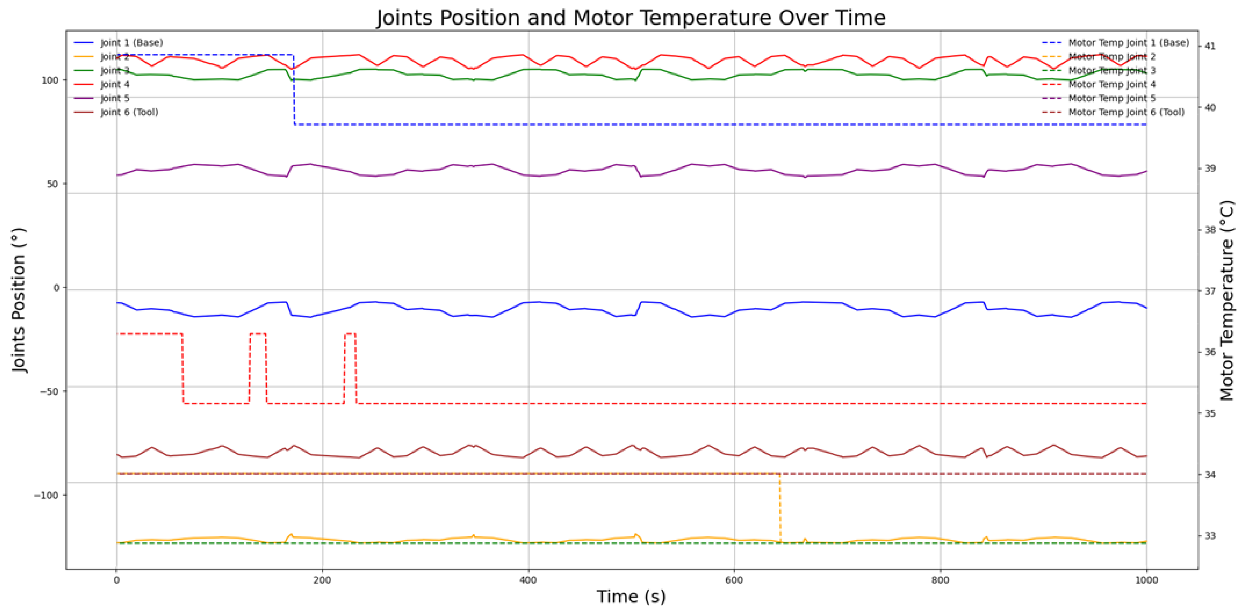
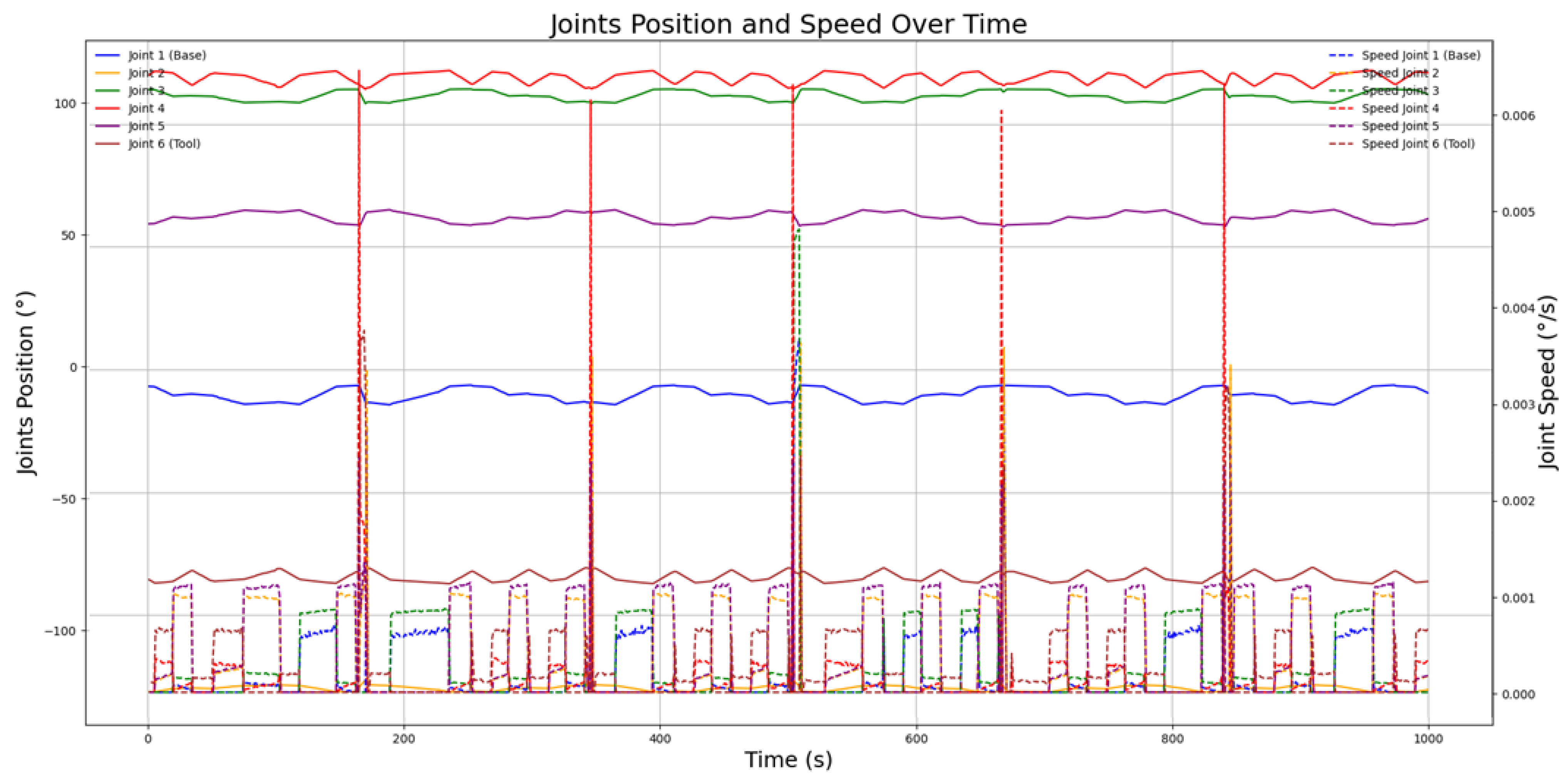
| Joint Position | The KUKA system retrieves the “ActualPosition” variable for each joint. | Represents the angular position of the six joints (from 1 to 6) in degrees. | “Joints_Position” |
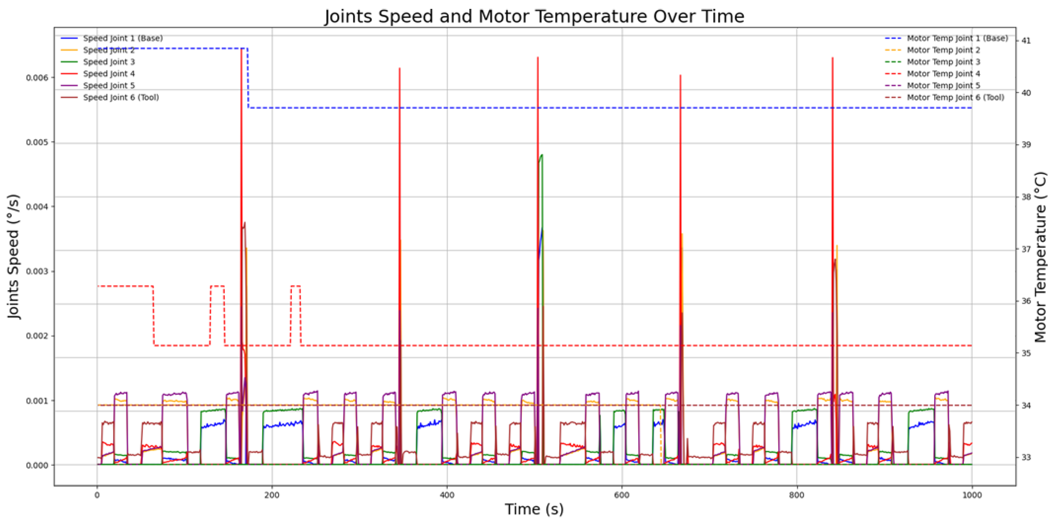
| Joint Speed | The KUKA system retrieves the “ActualSpeed” variable for each joint. | Indicates the angular speed of each joint in degrees per second. | “Joints_Speed” |
| Joint Motor Temperature | Accesses the “MotorTemperature” variable for each joint’s motor. | Displays the motor temperature for each joint in degrees Kelvin. | “Motor_Temperature” |
| Timestamp | Created in JavaScript for data transmission references. | Provides an instantaneous timestamp for the current data cycle. | “Timestamp” |
Disclaimer/Publisher’s Note: The statements, opinions and data contained in all publications are solely those of the individual author(s) and contributor(s) and not of MDPI and/or the editor(s). MDPI and/or the editor(s) disclaim responsibility for any injury to people or property resulting from any ideas, methods, instructions or products referred to in the content. |
© 2025 by the authors. Licensee MDPI, Basel, Switzerland. This article is an open access article distributed under the terms and conditions of the Creative Commons Attribution (CC BY) license (https://creativecommons.org/licenses/by/4.0/).
Share and Cite
Alvares, A.J.; Rodriguez, E.; Figueroa, B. Digital-Twin-Enabled Process Monitoring for a Robotic Additive Manufacturing Cell Using Wire-Based Laser Metal Deposition. Processes 2025, 13, 2335. https://doi.org/10.3390/pr13082335
Alvares AJ, Rodriguez E, Figueroa B. Digital-Twin-Enabled Process Monitoring for a Robotic Additive Manufacturing Cell Using Wire-Based Laser Metal Deposition. Processes. 2025; 13(8):2335. https://doi.org/10.3390/pr13082335
Chicago/Turabian StyleAlvares, Alberto José, Efrain Rodriguez, and Brayan Figueroa. 2025. "Digital-Twin-Enabled Process Monitoring for a Robotic Additive Manufacturing Cell Using Wire-Based Laser Metal Deposition" Processes 13, no. 8: 2335. https://doi.org/10.3390/pr13082335
APA StyleAlvares, A. J., Rodriguez, E., & Figueroa, B. (2025). Digital-Twin-Enabled Process Monitoring for a Robotic Additive Manufacturing Cell Using Wire-Based Laser Metal Deposition. Processes, 13(8), 2335. https://doi.org/10.3390/pr13082335