Article

The Voltage Regulation of Boost Converters via a Hybrid DQN-PI Control Strategy Under Large-Signal Disturbances

1
Division of Electronics and Informatics, Gunma University, Kiryu 376-8515, Japan
2
College of Intelligent Engineering, Hefei University of Economics, Hefei 230031, China
3
College of Automation, Jiangsu University of Science and Technology, Zhenjiang 212100, China
*
Author to whom correspondence should be addressed.
Processes 2025, 13(7), 2229; https://doi.org/10.3390/pr13072229
Submission received: 5 June 2025 / Revised: 8 July 2025 / Accepted: 10 July 2025 / Published: 12 July 2025
(This article belongs to the Special Issue Challenges and Advances of Process Control Systems)

Abstract

The DC-DC boost converter plays a crucial role in interfacing low-voltage sources with high-voltage DC buses in DC microgrid systems. To enhance the dynamic response and robustness of the system under large-signal disturbances and time-varying system parameters, this paper proposes a hybrid control strategy that integrates proportional–integral (PI) control with a deep Q-network (DQN). The proposed framework leverages the advantages of PI control in terms of steady-state regulation and a fast transient response, while also exploiting the capabilities of the DQN agent to learn optimal control policies in dynamic and uncertain environments. To validate the effectiveness and robustness of the proposed hybrid control framework, a detailed boost converter model was developed in the MATLAB 2024/Simulink environment. The simulation results demonstrate that the proposed framework exhibits a significantly faster transient response and enhanced robustness against nonlinear disturbances compared to the conventional PI and fuzzy controllers. Moreover, by incorporating PI-based fine-tuning in the steady-state phase, the framework effectively compensates for the control precision limitations caused by the discrete action space of the DQN algorithm, thereby achieving high-accuracy voltage regulation without relying on an explicit system model.

1. Introduction

Recently, DC microgrids have garnered significant attention due to their high energy transmission efficiency, simplified control architecture, and strong compatibility with renewable energy sources and energy storage devices [1]. As a key power conversion unit within DC microgrids, the boost converter plays a vital role in facilitating energy exchange among devices operating at different voltage levels, as shown in Figure 1. This DC bus voltage regulation capability is crucial in ensuring the stable operation of the microgrid, achieving optimal power flow control, and enhancing overall system reliability [2]. However, the highly dynamic nature of the loads and power sources in microgrids presents significant challenges in maintaining control performance under varying conditions [3].
Conventional proportional–integral (PI) controllers with fixed parameters are widely adopted in boost converter voltage regulation due to their simplicity, low implementation costs, and effectiveness under steady-state operating conditions. These controllers are typically designed based on small-signal or state-space models, enabling closed-loop voltage regulation in well-defined scenarios [4]. However, during actual operation, boost converters frequently encounter unpredictable nonlinear behaviors, such as abrupt changes in load resistance or input voltage fluctuations. These nonlinear disturbances can lead to significant variations in system parameters, thereby reducing the accuracy of the PI controller. As a result, conventional PI controllers often struggle to maintain the desired control performance under such conditions, which underscores the need for more robust and adaptive voltage control strategies capable of handling complex and time-varying operating environments.
To address the limitations of conventional PI controllers under nonlinear and time-varying conditions, researchers have proposed a variety of advanced control strategies, such as model predictive control (MPC) [5], sliding mode control (SMC) [6], and fuzzy logic control [7], to enhance the robustness and adaptability of voltage regulation systems. For instance, an MPC-based controller was developed for a versatile buck–boost (VBB) DC-DC converter to enable accurate reference current tracking while maintaining a quasi-constant steady-state switching frequency in [8]. Ref. [9] applied a fuzzy logic controller to a single-switch cascaded DC-DC boost converter, achieving a faster dynamic response and improved steady-state performance. Ref. [10] addressed the burden associated with long prediction horizons in MPC by proposing an improved algorithm with a single prediction horizon, significantly reducing the online computational complexity. Furthermore, ref. [11] presented a dual-loop SMC controller, incorporating both voltage and current control loops for boost converters. The experimental results demonstrated reductions in the steady-state error, overshoot, and settling time compared to conventional lead–lag controllers. While the above advanced control methods demonstrate strong robustness and excellent dynamic performance under sudden changes in load resistance or input voltage, they fundamentally rely on accurate system modeling and prior expert knowledge [12]. The effectiveness of these approaches often depends on precise mathematical models, carefully designed observers, or well-tuned fuzzy rule bases, which are typically derived through extensive analytical efforts or empirical experience. However, in practical industrial environments, the presence of complex load dynamics and measurement uncertainties often makes it difficult to obtain precise system models, thereby posing significant challenges to the implementation of these model-dependent control strategies.
In recent years, reinforcement learning (RL) has emerged as a promising model-free intelligent control method [13]. By interacting continuously with the environment, RL agents are capable of learning optimal control strategies without requiring an accurate mathematical model, aiming to maximize the long-term cumulative rewards. This characteristic makes RL particularly suitable for addressing complex nonlinear control problems. Motivated by this, many researchers have explored the application of deep reinforcement learning (DRL) techniques to the control of power electronic converters. A widely used strategy involves integrating the DRL algorithm as a compensatory mechanism alongside conventional controllers, such as SMC or PI controllers, in order to improve the system stability, robustness, and dynamic response. In [14], an auxiliary deep deterministic policy gradient (DDPG) algorithm was designed to compensate for the observation errors introduced by a sliding mode observer in a PI control system. The proposed approach outperformed traditional PI and MPC controllers by reducing the overshoot and improving the overall control performance. Ref. [15] utilized the RL algorithm to dynamically tune the parameters of a PI controller, significantly enhancing the robustness of the system under nonlinear disturbances. Similarly, ref. [16] proposed an optimal output regulation framework by combining robust stabilization and DRL. This method employed a high-order sliding mode observer (HOSMO) to estimate system uncertainties, followed by a feedforward compensation mechanism to improve dynamic recovery, with the DDPG algorithm adaptively adjusting the control gains in real time. In [17], an adaptive, model-independent control scheme was proposed for a two-coil series–series (SS) compensated wireless power transfer (WPT) system feeding a time-varying constant power load (CPL). This method integrates a deep DDPG-based intelligent feedback controller with a sliding mode observer under an ultra-local model (ULM) framework. By combining the learning capabilities of DDPG and the real-time estimation of system dynamics via SMO, the scheme successfully stabilizes the output voltage and addresses impedance-induced instabilities caused by CPLs. Although these hybrid control strategies incorporating RL as a compensator demonstrate improved control performance compared to traditional methods and promote the application of RL in power electronics, most approaches still depend on partial knowledge of the system dynamics or observer-based state estimation and thus cannot achieve fully model-free control.
Another widely used method involves the direct application of RL algorithms in the control of DC-DC converters, enabling the system to learn optimal control policies from interaction with the environment, without relying on accurate system models. Ref. [18] applied the DDPG algorithm to track the reference voltage of the buck converter, even in a dynamic environment. The twin delayed deep deterministic policy gradient (TD3) algorithm was applied to optimize the efficiency of a dual active bridge converter by minimizing power losses in [19]. The method successfully enabled soft switching for different operating conditions, showcasing the potential of continuous-action DRL algorithms in complex converter control. A well-established DRL algorithm based on proximal policy optimization (PPO) was proposed to achieve near-optimal control of a buck converter operating in both continuous conduction mode (CCM) and discontinuous conduction mode (DCM), under resistive and inductive load conditions, in ref. [20]. The effectiveness and robustness of the PPO-based controller were validated through both simulations and experimental results. The above continuous-action reinforcement learning (RL) algorithms, such as TD3, DDPG, and PPO, offer finer control granularity compared to discrete-action methods. However, this advantage comes at the cost of significantly increased computational complexity. These algorithms typically require a substantially larger number of training episodes to achieve convergence, resulting in prolonged learning times and excessive computational burdens.
Compared to continuous-action reinforcement learning (RL) methods, discrete-action algorithms offer practical advantages in terms of deployment simplicity, training stability, and convergence speeds, making them particularly beneficial for power electronic systems. Among discrete-action algorithms, the deep Q-network (DQN) stands out for its ability to handle high-dimensional, nonlinear states, using deep neural networks to approximate the Q-value function. Ref. [21] applied the DQN algorithm directly to a buck converter with a constant power load (CPL), demonstrating the feasibility of achieving stable control in discrete action spaces. However, due to the inherent discretization of the action space, which selects from a finite set of predefined control actions (e.g., duty cycles), the control precision is limited, making it difficult to achieve precise and wide-range voltage regulation.
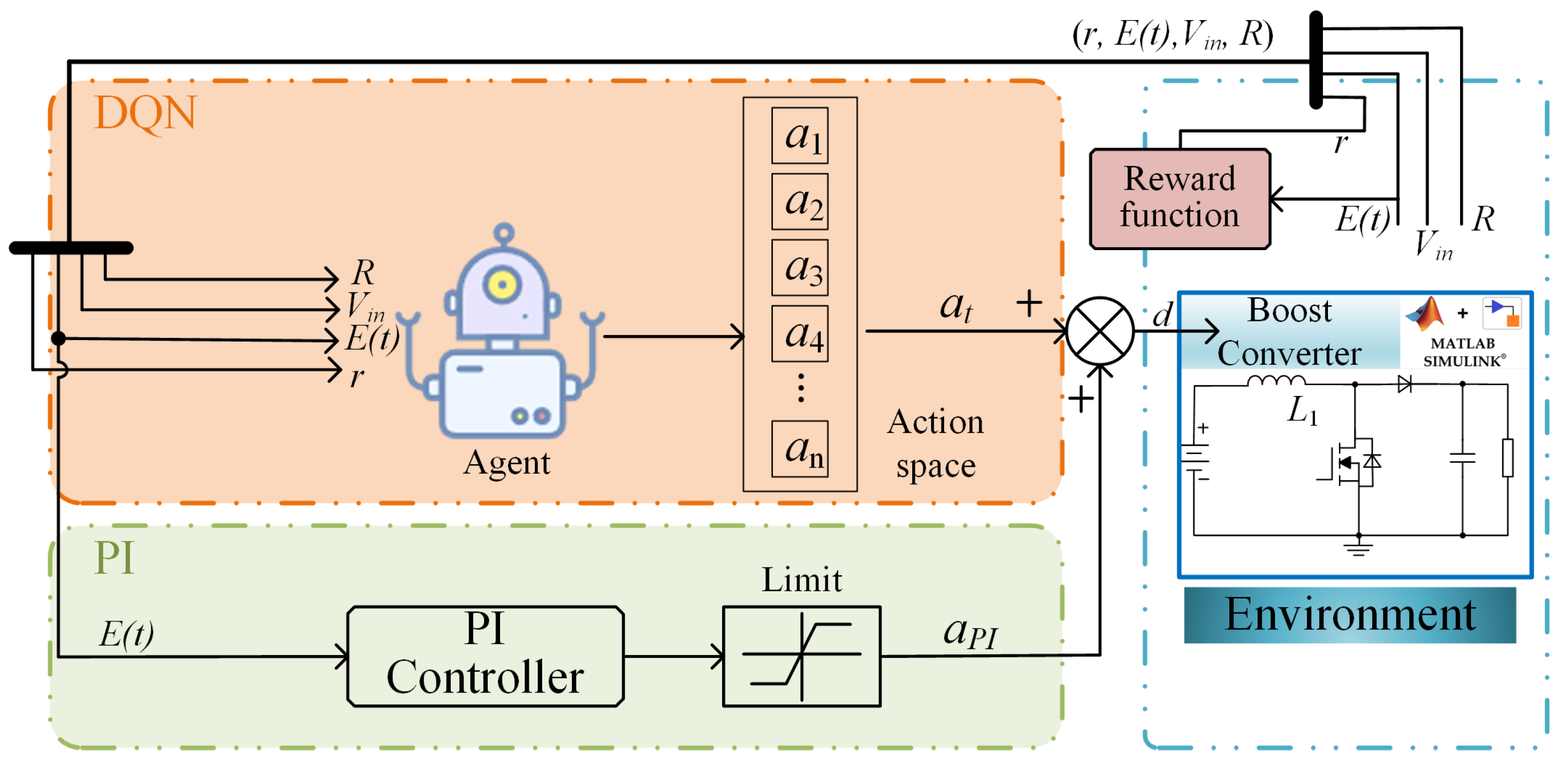
To address the issue of limited control precision in the steady state caused by the discrete nature of the action space in DQN-based controllers, this paper introduces a hybrid control strategy that combines the DQN with a conventional PI controller, as shown in Figure 2. In this approach, the DQN is responsible for learning control policies and improving the dynamic response, while the PI controller ensures high steady-state accuracy. This approach effectively overcomes the resolution limitations associated with discrete action spaces and achieves superior dynamic and steady-state performance without requiring a detailed system model. As such, it offers a promising solution for practical applications in power electronics.
The remainder of this manuscript is organized as follows. Section 2 introduces the control target and outlines the principles of the DQN. In Section 3, the proposed hybrid control strategy that combines the DQN with a PI controller is described in detail, including its structure and implementation. Section 4 presents the development of the simulation model in the MATLAB/Simulink environment and discusses the corresponding performance evaluations. Finally, Section 5 concludes the paper.

2. Problem Formulation and DQN Revisit

2.1. Problem Formulation

Figure 1 illustrates the simplified diagram of a boost converter, where energy sources such as photovoltaic panels or batteries are interfaced with the DC bus through the boost converter to regulate the voltage and enable efficient energy transfer. The output voltage of the boost converter is regulated by the duty cycle d of the MOSFET Q 1 . Traditionally, the average model, shown in Equation (1), is developed to analyze the boost converter and facilitate the design of an effective closed-loop control strategy. Here, V i n and V o u t denote the input and output voltages, respectively. L and C are the inductor and the capacitor, respectively. R L represents the equivalent resistance. Additionally, the inductor L functions as an essential energy storage element that maintains current continuity and suppresses voltage fluctuations during large-signal disturbances, such as abrupt changes in the load or input voltage.
d i L d t = 1 L ( V in ( 1 d ) V out ) d V out d t = 1 C ( 1 d ) i L V out R L
However, due to the uncertainty of disturbances, the input voltage and load resistance may change, making the design of a closed-loop PI controller difficult. To address this issue, this paper proposes a hybrid algorithm integrating the DQN and PI to control the output voltage of the boost converter. The control object is to stabilize the output voltage V o u t , even under conditions of sudden load resistance and large input voltage disturbances.

2.2. DQN Algorithm Revisit

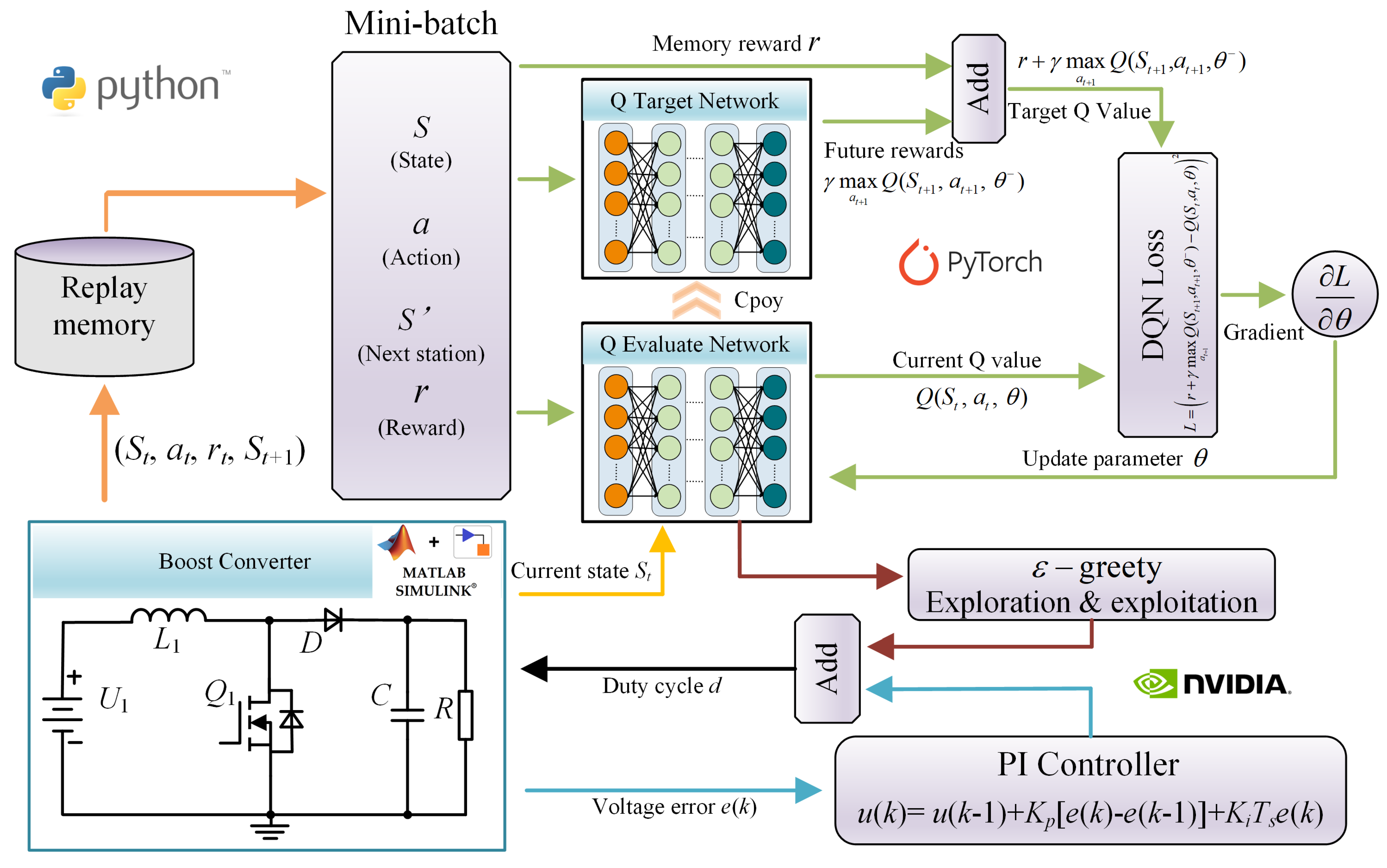
RL is an important branch of machine learning that enables agents to learn optimal control strategies through continuous interaction with the environment and feedback in the form of rewards. By iteratively adjusting the policy based on the received rewards, RL demonstrates strong adaptability in the dynamic environment, making it highly promising in a wide range of fields, such as autonomous driving, robotics, and power electronics. Among various RL algorithms, the DQN stands out due to its superior performance in high-dimensional state spaces and excellent generalization capabilities. As a result, it has become one of the most widely applied intelligent control algorithms in the field of power electronics. The flowchart of the DQN algorithm is shown in Figure 3.
The DQN problem can be formulated as a Markov decision process (MDP), which is defined by the tuple { S , A , R , P , r } , where S is the state space, A represents the action space, R denotes the reward set, P is the state transition probability, and r is the reward function. At each time step t, the agent observes the current state s t , selects and executes an action a t , and then transitions to a new state s t + 1 with a reward r t + 1 corresponding to the selected action. The DQN algorithm is a value-based reinforcement learning method aimed at maximizing the accumulated rewards E k = 0 T γ k r t + k . At each time step, after the agent interacts with the environment, the current Q value y i is updated according to the following equation:
y i = r j , if episode terminates at step j + 1 r j + γ max a Q ( s j + 1 , a t + 1 , θ ) , otherwise
where γ is the discount factor. During the interaction between the agent and the environment in the DQN algorithm, the tuple consisting of the current state, action, reward, and next state ( s , a , r , s ) is stored in a replay buffer. During the training process, a mini-batch of samples is randomly drawn from the replay buffer to update the neural network. The DQN framework consists of two neural networks with identical architectures, denoted as the evaluation network and the target network, respectively. The evaluation network is used to estimate the action value function Q ( s , a ; θ ) under the current policy, and its parameters are updated at every training step via backpropagation. The target network, on the other hand, is used to compute the target value in the temporal difference (TD) error. Its parameters are periodically updated by copying the weights from the evaluation network. This mechanism stabilizes the target values and mitigates training instabilities such as oscillations and divergence. A loss function L ( θ ) , defined as the mean squared error (MSE) between the predicted Q-value from the evaluation network and the target Q-value from the target network, is introduced to guide the parameter updates of the neural network, as shown in Equation (3):
L ( θ ) = E [ ( r + γ max a t + 1 Q ( s t + 1 , a t + 1 ; θ ) Q ( s t , a t ; θ ) ) 2 ]
In the DQN framework, the agent inputs the current state s t into the evaluation network to obtain the estimated Q-values for all possible actions, denoted as Q ( s t , a t ; θ ) . An action a t is then selected based on the ε -greedy policy, which balances exploration and exploitation. Specifically, with probability ε , the agent selects a random action to explore potentially better strategies and avoid being trapped in a local optimum. With probability 1 ε , the agent chooses the action that maximizes the estimated Q-value. Thus, at each time step t, the action a t chosen by the agent under the ε -greedy policy can be described as
a t = arg max a Q ( s t , a ; θ ) , if p > ε a random , otherwise
This exploration–exploitation policy allows the agent to sufficiently explore the environment during the training process while gradually shifting towards exploiting learned knowledge as the policy improves. In this study, the value of ε starts from a high value to encourage exploration in the early stages of training and decays to a lower value to promote more deterministic, reward-maximizing behavior as learning progresses.

3. Control System Design

The control system is composed of a DQN and a PI controller, where the DQN is responsible for learning and adapting to larger-signal disturbances, while the PI controller ensures high-precision regulation in the steady state by compensating for the inherent limitations of the discrete action space in the DQN algorithm. Figure 4 shows the framework of our proposed hybrid algorithm. In this integrated framework, the DQN algorithm continuously interacts with the environment to learn and optimize its control strategy, enabling it to effectively handle nonlinear operating conditions such as large load disturbances or variations in the input voltage. Meanwhile, the PI controller serves to refine and correct the output of the DQN controller, ensuring a fast and stable system response. This cooperative mechanism not only improves the overall steady-state control performance of the system but also enhances its robustness and adaptability to unknown disturbances.

3.1. State Space

In the proposed control strategy, the error between the actual output voltage and the reference voltage, denoted as the voltage error e ( t ) , is considered one of the most critical feedback signals, directly reflecting the control performance. Therefore, it serves as a key component of the system state representation. Simulations involving sudden changes in load and input voltage are conducted to evaluate the effectiveness and robustness of the proposed hybrid control framework. Accordingly, both the load resistance and input voltage are also included as observed variables in the system state, as their variations significantly affect the system’s dynamic behavior and control requirements. Hence, the system state is defined as a vector composed of multiple features that collectively characterize the current operating condition of the converter. Specifically, the state space is designed as S t = e ( t ) , v i n ( t ) , R ( t ) .

3.2. Action Space

The DQN algorithm is inherently designed for control problems with discrete action spaces. Its core principle lies in approximating the optimal policy by selecting actions from a finite set. In this study, the switching duty ratio of the boost converter is selected as the control variable for the construction of a discrete action space. The approximate range of the duty cycle is estimated based on the ratio between the desired output voltage and the actual input voltage under steady-state conditions. To define the action space more systematically, the discrete action space A is defined as in Equation (5):
A = { D φ + k c | k = 0 , 1 , 2 , 2 φ c }
where the parameters D, φ , and c, respectively, represent the nominal duty ratio, the fluctuation range, and the minimum step. These can be flexibly tuned according to the system dynamics and the desired control precision, allowing the discrete action space to strike a balance between learning efficiency and control accuracy.

3.3. Reward Function

The control objective is to accurately track the reference voltage. The design of the reward function plays a crucial role in both the learning efficiency and the ultimate performance of the agent. A piecewise reward function, depicted in Equation (6), is adopted in this work to guide the agent by incorporating two subgoals ε 1 and ε 2 , which represent specific targets related to the control error. These subgoals help to shape the learning process toward accurate and stable voltage regulation. In this study, ε 1 and ε 2 are set to 0.2 and 1, respectively, based on empirical testing for complex and dynamic control environments.
r ( t ) = β 1 β 3 | e ( t ) | , if | e ( t ) | ε 1 β 2 β 3 | e ( t ) | , if ε 1 < | e ( t ) | ε 2 β 3 | e ( t ) | , otherwise

3.4. DNN Design

In the traditional Q-learning algorithm, the agent selects an action by consulting a Q-table, choosing the one with the highest Q-value for the current state. However, in the DQN algorithm, Q-values are no longer stored in a tabular format. Instead, a neural network is employed to predict the Q-value corresponding to each possible action, given the current state as input. The agent then selects the action associated with the highest predicted Q-value, effectively integrating value function approximation with policy decision-making.
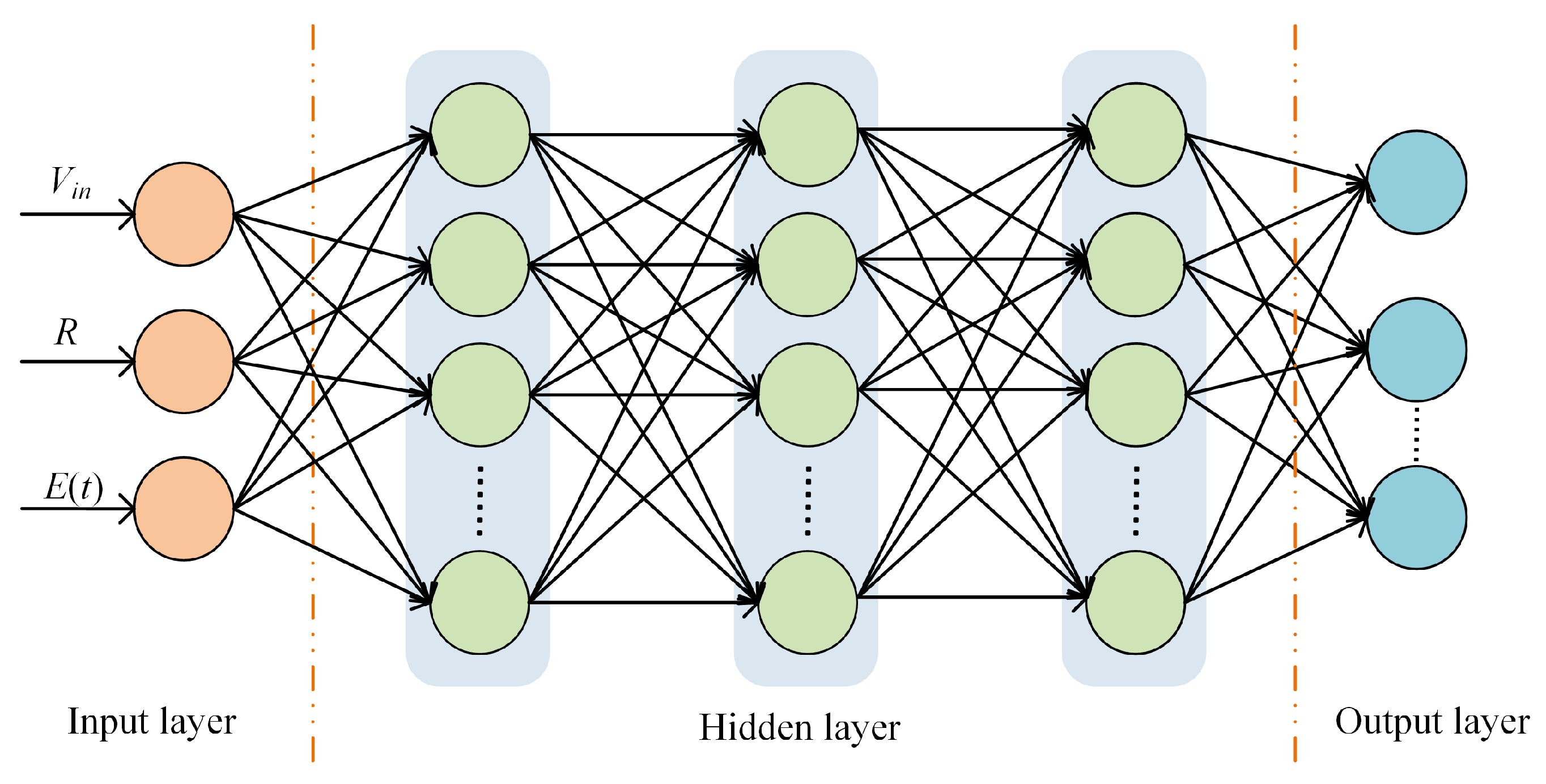
The architecture of the neural network used in this study is illustrated in Figure 5. It consists of an input layer, three hidden layers, and an output layer. The input layer receives three features that characterize the system state: the tracking error e ( t ) , the input voltage V in , and the load resistance R L . The output layer produces a vector whose length equals the number of discrete actions; each element of this vector represents the estimated Q-value for the corresponding action under the given state.
Additionally, all three hidden layers are fully connected and comprise 64 neurons each. This network structure strikes a balance between expressive power and computational efficiency, making it suitable for real-time control scenarios in power electronic systems. Moreover, the rectified linear unit (RLU) is used as the activation function in all hidden layers, which provides the advantages of a low computational cost and high training efficiency.

3.5. PI Controller Design

In the proposed hybrid control framework, the PI controller is designed to provide a compensation signal to compensate for the action output generated by the DQN agent. Specifically, after the DQN outputs a preliminary control action a t (k) based on the current system state, the PI controller computes an adjustment term a P I based on the error between the reference voltage and the actual output voltage. The Tustin method is employed for discretization to implement the PI controller in a digital control system with high fidelity to its continuous-time dynamics. The expression of the discrete PI control is shown in Equation (7):
u ( k ) = u ( k 1 ) + K p [ e ( k ) e ( k 1 ) ] + K i T s e ( k )
where K p denotes the proportional gain and K i denotes the integral gain. T s represents the sampling period. In this study, the sampling time of the PI controller is set to 2 × 10 5 s. After parameter tuning, K p is set to 0.000082, and K i is set to 0.00008. Additionally, the limit of PI controller ς ensures that the PI controller primarily performs fine-tuning around the DQN output, without overriding the learning-based decision-making process. Furthermore, the parameter ς can be flexibly adjusted according to the system requirements, and its impact on the control precision, convergence speed, and robustness can be systematically investigated in subsequent studies.

4. Simulation Verification

4.1. Simulation Configuration

To verify the effectiveness and robustness of the proposed hybrid control strategy, a detailed boost converter simulation model was constructed in the MATLAB/Simulink environment. The key electrical parameters of the boost converter are summarized in Table 1. It should be noted that the boost converter operated in continuous conduction mode (CCM) throughout all simulation scenarios. The DQN architecture was developed using the PyTorch 2.2.2 framework, and its associated hyperparameters used for the training of the agent are presented in Table 2. The DQN network training was accelerated using an NVIDIA RTX 3060 GPU with 12 GB of memory, which significantly improved the computational efficiency and reduced the training time. To enable real-time interaction between the control algorithm and the Simulink-based boost converter model, the MATLAB 2024–Python 3.11 engine API was employed, allowing seamless bidirectional data exchange during the learning and control process.
The simulation system was configured with a fixed-step discrete solver to ensure consistency in time-domain analysis and accurate modeling of the switching behavior. A simulation time step of 1 μ s was selected to capture high-frequency switching dynamics, while the control interval for the DQN agent was set to 0.01 s, allowing the agent sufficient time to observe the system dynamics and update its control actions accordingly.

4.2. Comparative Performance Evaluation of PI, DQN, and DQN+PI Controllers

To validate the effectiveness and robustness of the proposed hybrid PI+DQN control strategy for the DC-DC boost converter, disturbance experiments were conducted in the MATLAB/Simulink environment. The total simulation time was set to 1.5 s. Two major disturbances were introduced to evaluate the adaptability of the control system under dynamic operating conditions.
  • Load Step Disturbance: At t = 0.5 s, the load resistance was abruptly increased from 10   Ω to 30   Ω , corresponding to a 200% increase.
  • Input Voltage Drop Disturbance: At t = 1.0 s, the input voltage was reduced from 100   V to 80   V , representing a 20% drop.
The reference output voltage was set to V r e f = 200   V . The DQN agent was configured with a discrete action space by modulating the switching duty cycle in the range of [ 0.4 , 0.6 ] with a step of 0.02.
Figure 6 illustrates the simulation results of the three control strategies during the system startup phase. It can be seen that, during the initial startup interval (0–0.06 s), the PI controller requires approximately 0.058 s to drive the output voltage to the reference value of 200 V, whereas the DQN controller takes about 0.35 s to achieve the same level of tracking. By contrast, the proposed hybrid DQN+PI strategy accomplishes this task in only 0.02 s, thereby demonstrating its superior capabilities for rapid and accurate voltage regulation during the transient startup phase. Furthermore, inspection of the steady-state waveform between 0.30 s and 0.31 s reveals that, under DQN control, the average output voltage settles at approximately 196 V and fails to precisely reach the reference voltage of 200 V, which is caused by the discretization inherent in the DQN’s action space. In comparison, both the PI controller and the hybrid DQN+PI control strategy maintain the output voltage exactly at the reference voltage of 200 V, confirming that the integration of PI and the DQN not only accelerates convergence during the startup phase but also rectifies the steady-state tracking error introduced by the discrete-action DQN framework.
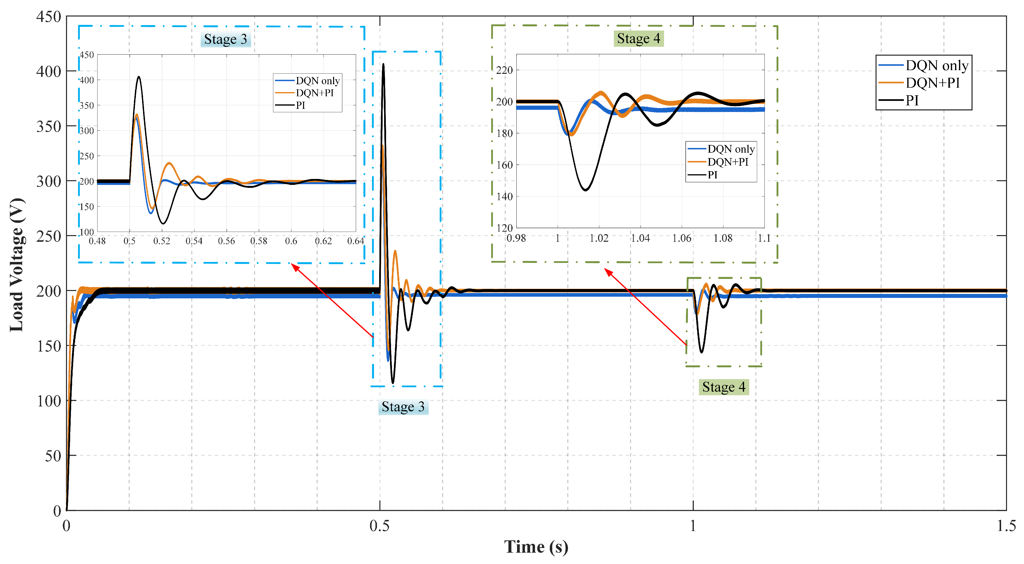
Figure 7 shows the dynamic response simulation results during the load step disturbance and input voltage drop. It can be seen that, upon a load disturbance, the PI controller requires approximately 0.14 s to return to a steady state of 200 V, with a maximum overshoot of 103%. Under the control of the DQN, the system reaches a steady state of 196 V in just 0.051 s, exhibiting a lower overshoot of 62%. The proposed hybrid DQN+PI control strategy restores steady-state operation of 200 V in 0.085 s with a peak overshoot of 65%. Table 3 shows the detailed performance comparison of the different controllers. These results indicate that the DQN controller outperforms the PI controller in terms of the transient response speed and adaptability to nonlinear disturbances, making it highly effective in handling sudden system changes. However, the DQN controller exhibits inferior steady-state performance, as evidenced by the persistent steady-state error. In contrast, both the PI controller and the hybrid DQN+PI strategy demonstrate superior steady-state accuracy. Overall, the proposed hybrid DQN+PI control strategy effectively combines the fast adaptability of the DQN with the steady-state accuracy of PI control. It achieves superior robustness under sudden load and input voltage disturbances while maintaining precise voltage regulation under a steady state, demonstrating strong overall control performance.
Due to the incorporation of an exploration strategy during the training process, the rewards obtained by the agent in each episode exhibit fluctuations. A smoothing technique is applied to better capture the underlying trends in the agent’s performance and reduce the influence of stochastic variability. Specifically, a moving average filter with a window size of five is employed to compute the mean reward over the most recent five episodes to represent the agent’s learning progress. The reward curves of the different control strategies over the training episodes are shown in Figure 8. As shown in Figure 8, the PI controller consistently yields a fixed reward across episodes, as its parameters remain unchanged during training. In contrast, the DQN agent exhibits a gradual improvement in performance with increased training episodes, eventually converging to a stable policy. The steady-state reward attained by the DQN agent surpasses that of the PI controller, indicating enhanced control effectiveness. Moreover, the proposed DQN+PI hybrid control architecture demonstrates a significantly faster convergence rate compared to the DQN approach. In the steady state, it also achieves higher cumulative rewards, highlighting its superior capabilities in terms of both learning efficiency and control performance.

4.3. Impact of PI Output Saturation Limit on System

As illustrated in Figure 4, the control signal of the boost converter is composed of two parts: the action output generated by the DQN agent and the compensatory signal from the PI controller. In this hybrid control architecture, the PI controller primarily serves to fine-tune the output voltage and eliminate steady-state errors introduced by the discrete nature of the DQN’s action space. However, the effectiveness of this compensation is directly influenced by the output saturation limit of the PI controller. Specifically, the saturation bound determines the extent to which the PI controller can contribute to the overall control action. A limit that is too small may restrict the PI controller’s ability to correct errors effectively, while an excessively large limit could introduce instability. Therefore, to investigate the impact of PI output saturation ς on the overall system performance, the impact of the PI output saturation limit on the system was simulated by varying the PI output saturation range [ ς , ς ], where ς represents the maximum output of the PI controller.
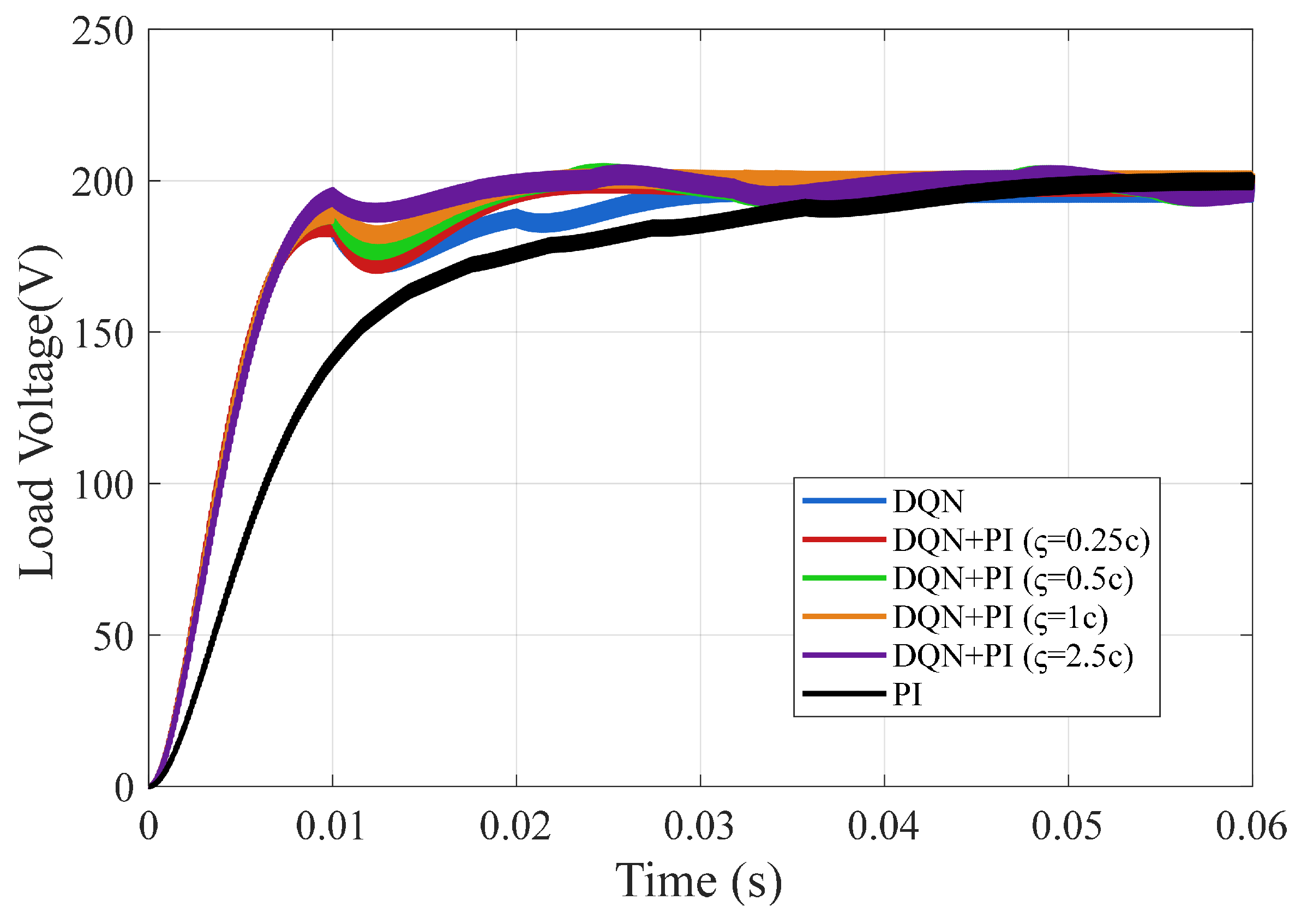
Figure 9 illustrates the control performance of the system under various control strategies—PI, DQN, and DQN+PI—with differing PI limit values during the startup process. The simulation results show that the PI controller requires approximately 0.06 s to regulate the output voltage to the reference value. In contrast, both the DQN controller and the DQN+PI hybrid strategy achieve faster voltage regulation across all tested PI limit settings.
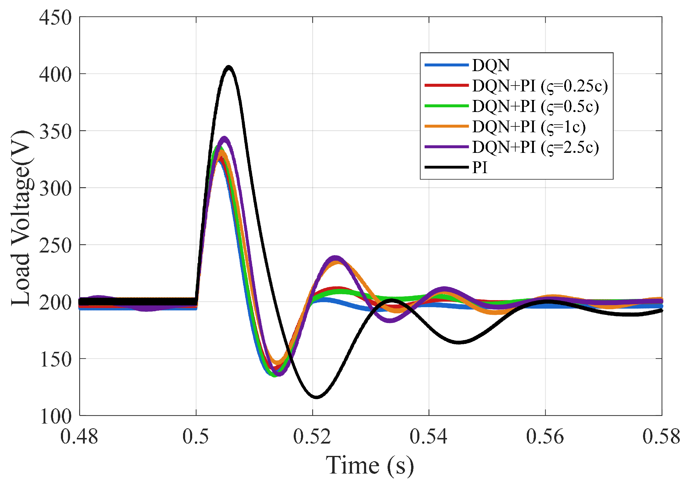
Figure 10 shows the simulation results under various control modes—PI, DQN, and DQN+PI—with differing PI limit values during the load changing process (from 10 ohms to 30 ohms). It is evident that, when addressing significant load disturbances, both the DQN and the proposed hybrid control strategy exhibit a faster response speed compared to the PI controller. The DQN algorithm can achieve a steady state within 0.04 s and effectively manage large-scale load changes. In contrast, the proposed DQN+PI hybrid architecture demonstrates a response speed that is superior to that of the PI controller, although it is slightly slower than that of the DQN controller. Furthermore, as the limit value of the PI controller increases, the stability of the system diminishes, resulting in a longer recovery time to reach a steady state.
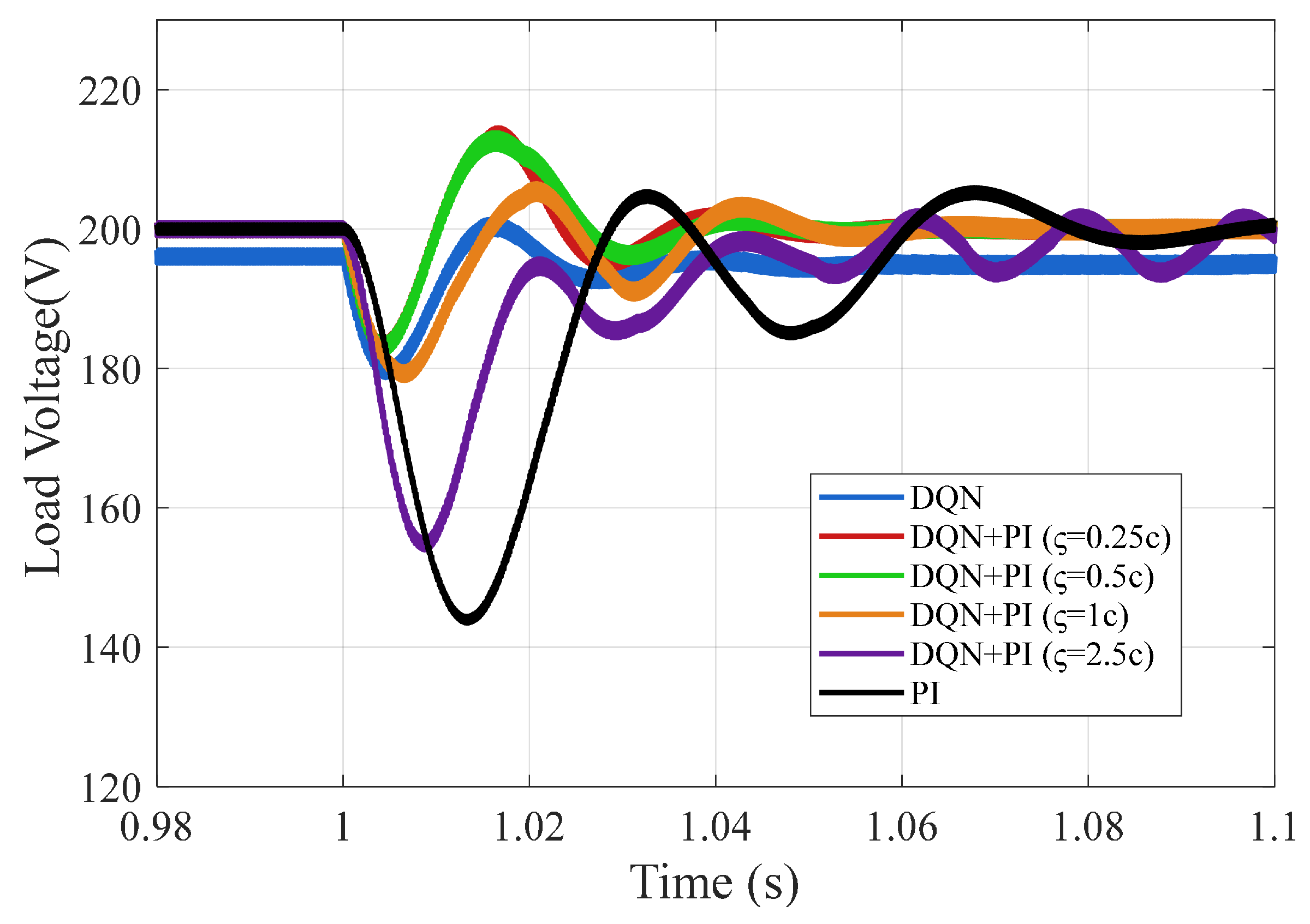
Figure 11 presents the system response to a significant input voltage drop from 100 V to 80 V. During the input voltage disturbance, the DQN controller exhibits the fastest response, requiring only 0.04 s to re-establish the steady-state voltage. However, it fails to eliminate the steady-state error, as observed in the 0.98–1 s interval. In contrast, both the PI controller and the proposed DQN+PI hybrid strategy successfully maintain accurate steady-state tracking of the reference voltage of 200 V. Furthermore, the simulation results show that the saturation limit of the PI controller significantly affects the system performance. As ς increases, the system has a larger voltage overshoot and this negatively impacts the system’s dynamic stability. When the saturation limit is excessively large, such as 2.5c, the system fails to achieve steady-state voltage tracking.
Thus, from Figure 10 and Figure 11, it can be seen that the output saturation limit of the PI controller significantly influences the overall control performance of the hybrid DQN+PI system. Specifically, increasing the PI limit value enhances the system’s transient response speed during startup and its steady-state tracking performance. However, this improvement comes at the cost of increased voltage overshoot and reduced system stability during large-signal disturbances. When the PI output constraint becomes excessively large (e.g., 2.5c), the system fails to maintain steady-state voltage tracking and exhibits oscillatory behavior. Therefore, there exists a critical trade-off between control responsiveness and system robustness. An appropriately constrained PI output ensures fast convergence while preserving steady-state accuracy and system stability, which is essential for reliable operation under dynamic conditions.

4.4. Performance Comparison with PI and Fuzzy Control

To validate the performance of the proposed control strategy, it is essential to conduct a comparative analysis with conventional control methods known for their robustness. Among these, the fuzzy logic controller (FLC) stands out as a widely used nonlinear control approach capable of effectively handling system uncertainties and nonlinearities. Unlike the classical PI controller, which relies on an accurate mathematical model, the FLC utilizes linguistic rules and reasoning, offering superior adaptability and robustness in dynamic and uncertain environments. In this study, a fuzzy logic controller is designed to regulate the output voltage of the boost converter. The overall control architecture, as illustrated in Figure 12, comprises three main phases.
  • Phase 1: Input Signal Preprocessing. The controller receives the instantaneous voltage error E ( t ) and its rate of change Δ E ( t ) as input variables. These signals are normalized through gain blocks (Gain1 and Gain2) to ensure compatibility with the fuzzy inference system’s universe of discourse. Two limiters are used to constrain the input ranges with predefined bounds before feeding them into the fuzzy controller.
  • Phase 2: Fuzzy Controller. The fuzzy controller, consisting of fuzzification, rule evaluation, and defuzzification stages, was implemented using MATLAB’s Fuzzy Logic Toolbox. Both input and output variables are defined using seven triangular membership functions, covering the linguistic range from Negative Big (NB) to Positive Big (PB). The rule base, constructed based on the system dynamics, is summarized in Table 4.
  • Phase 3: Output Signal Processing. The fuzzy controller produces a duty cycle adjustment signal Δ d , which is scaled using a gain block (Gain3) to tailor its magnitude. The final PWM duty cycle applied to the boost converter is determined as
    d ( t ) = d ( t 1 ) + Δ d
After completing the design of the fuzzy logic controller, a comparative analysis was conducted between the proposed hybrid controller, the fuzzy controller, and the conventional PI controller. Figure 13 presents the transient response of the system during the startup phase (0–0.12 s). It can be seen that the PI controller requires approximately 0.06 s to regulate the output voltage to the preset reference voltage. In contrast, the fuzzy controller achieves this in around 0.04 s. Notably, the proposed DQN+PI hybrid controller completes voltage regulation within only 0.02 s, demonstrating the fastest dynamic response among all three controllers. These results highlight the superior startup performance of the proposed controller.
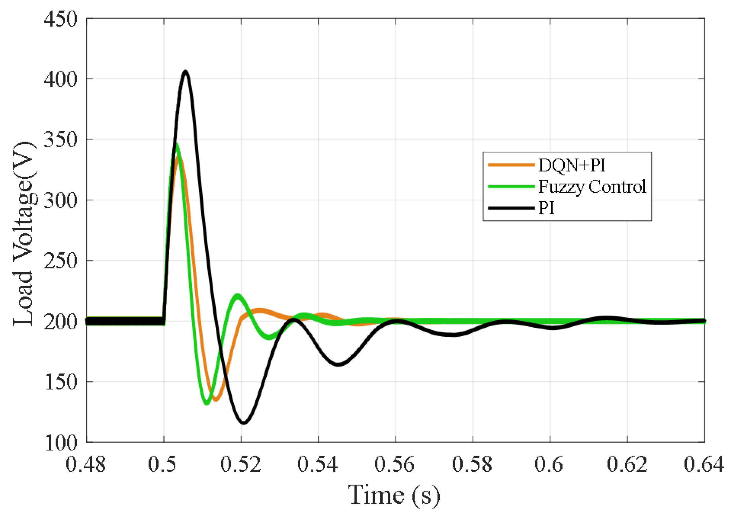
Figure 14 depicts the system behavior under a load step disturbance, where the load resistance abruptly increases from 10 ohms to 30 ohms (a 200% step change). The PI controller exhibits significant degradation in performance under this condition, with the output voltage overshooting to nearly twice the reference level and requiring up to 0.14 s to recover to a steady state. In comparison, both the fuzzy controller and the proposed DQN+PI controller successfully restore the output voltage within approximately 0.04 s, representing a 71.4% reduction in recovery time compared to the PI controller. Moreover, although the fuzzy and proposed controllers exhibit similar settling times, the proposed controller achieves a slightly lower peak overshoot, indicating better transient suppression performance.
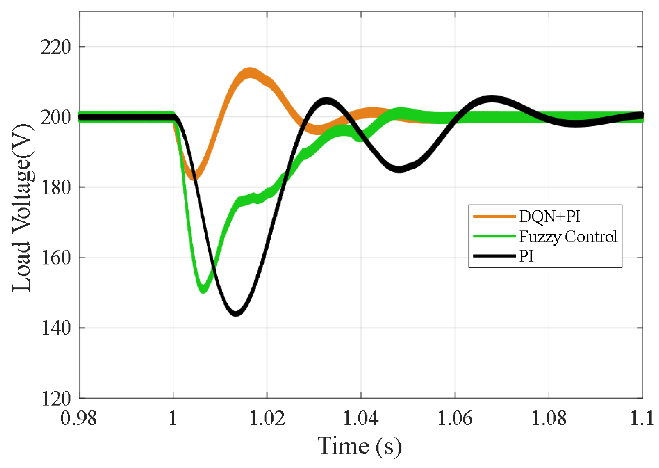
Figure 15 shows the system’s response to an input voltage drop disturbance, in which the input voltage suddenly drops from 100 V to 80 V at t = 1 s. The PI controller is significantly affected, requiring more than 0.1 s to stabilize the output voltage and exhibiting a maximum undershoot of 23%. Both the fuzzy controller and the proposed controller respond more promptly, with settling times of around 0.05 s. The proposed DQN+PI controller exhibits only 6.5% overshoot, while the fuzzy controller suffers from 25% undershoot, indicating better transient performance and disturbance rejection.
From Figure 13, Figure 14 and Figure 15, it can be seen that the proposed hybrid control strategy outperforms both the conventional PI controller and the fuzzy logic controller across all tested scenarios. Under challenging conditions, such as load step changes and input voltage disturbances, the proposed hybrid controller exhibits a faster response and improved disturbance rejection capabilities. Specifically, the proposed controller exhibits the fastest transient response during the startup phase. These results validate both the effectiveness and robustness of the proposed control scheme in enhancing the dynamic voltage regulation performance of the boost converter.

5. Conclusions

This paper proposes a hybrid voltage regulation strategy that integrates a DQN with a traditional PI controller to address the challenges of accurate and robust control in boost converters under nonlinear disturbances and model uncertainties. The proposed DQN+PI hybrid control scheme employs the DQN output as feedforward compensation to enhance the dynamic response, while the PI controller ensures steady-state accuracy. The simulation results validate the effectiveness of the proposed approach during the startup process. Additionally, the influence of different PI output limit values on system stability has been anlayzed. The proposed hybrid strategy provides a practical, model-free, and high-performance solution for voltage regulation in power electronic systems, with promising prospects for real-world applications. In further work, the proposed hybrid control scheme can be implemented on a real-time platform such as dSPACE, which is fully compatible with MATLAB/Simulink. This enables the seamless deployment of the control algorithm directly from our simulation environment to real hardware with minimal modification.

Author Contributions

Conceptualization, S.X. and S.H.; methodology, S.H.; software, P.N.; validation, Y.W. and Z.W.; formal analysis, P.N.; investigation, S.X.; resources, P.N.; data curation, T.K.; writing—original draft preparation, P.N.; writing—review and editing, S.X.; visualization, S.X.; supervision, S.H.; project administration, S.X.; funding acquisition, S.H. All authors have read and agreed to the published version of the manuscript.

Funding

This research received no external funding.

Data Availability Statement

Data are contained within the article.

Conflicts of Interest

The authors declare no conflicts of interest.

References

  1. El-Shahat, A.; Sumaiya, S. DC-Microgrid System Design, Control, and Analysis. Electronics 2019, 8, 124. [Google Scholar] [CrossRef]
  2. Jithin, K.; Haridev, P.P.; Mayadevi, N.; Harikumar, R.P.; Mini, V.P. A Review on Challenges in DC Microgrid Planning and Implementation. J. Mod. Power Syst. Clean Energy 2022, 11, 1375–1395. [Google Scholar] [CrossRef]
  3. Al-Ismail, F.S. DC Microgrid Planning, Operation, and Control: A Comprehensive Review. IEEE Access 2021, 9, 36154–36172. [Google Scholar] [CrossRef]
  4. Özdemir, A.; Erdem, Z. Double-Loop PI Controller Design of the DC-DC Boost Converter with a Proposed Approach for Calculation of the Controller Parameters. Proc. Inst. Mech. Eng. Part I J. Syst. Control Eng. 2018, 232, 137–148. [Google Scholar] [CrossRef]
  5. Hu, J.; Shan, Y.; Guerrero, J.M.; Ioinovici, A.; Chan, K.W.; Rodriguez, J. Model Predictive Control of Microgrids—An Overview. Renew. Sustain. Energy Rev. 2021, 136, 110422. [Google Scholar] [CrossRef]
  6. Komurcugil, H.; Biricik, S.; Bayhan, S.; Zhang, Z. Sliding mode control: Overview of its applications in power converters. IEEE Ind. Electron. Mag. 2020, 15, 40–49. [Google Scholar] [CrossRef]
  7. Siano, P.; Citro, C. Designing fuzzy logic controllers for DC-DC converters using multi-objective particle swarm optimization. Electr. Power Syst. Res. 2014, 112, 74–83. [Google Scholar] [CrossRef]
  8. Restrepo, C.; Barrueto, B.; Murillo-Yarce, D.; Muñoz, J.; Vidal-Idiarte, E.; Giral, R. Improved Model Predictive Current Control of the Versatile Buck-Boost Converter for a Photovoltaic Application. IEEE Trans. Energy Convers. 2022, 37, 1505–1519. [Google Scholar] [CrossRef]
  9. Kart, S.; Demir, F.; Kocaarslan, İ.; Genc, N. Increasing PEM Fuel Cell Performance via Fuzzy-Logic Controlled Cascaded DC-DC Boost Converter. Int. J. Hydrogen Energy 2024, 54, 84–95. [Google Scholar] [CrossRef]
  10. Li, Y.; Sahoo, S.; Dragičević, T.; Zhang, Y.; Blaabjerg, F. Stability-Oriented Design of Model Predictive Control for DC/DC Boost Converter. IEEE Trans. Ind. Electron. 2023, 71, 922–932. [Google Scholar] [CrossRef]
  11. Inomoto, R.S.; de Almeida Monteiro, J.R.B.; Sguarezi Filho, A.J. Boost Converter Control of PV System Using Sliding Mode Control with Integrative Sliding Surface. IEEE J. Emerg. Sel. Top. Power Electron. 2022, 10, 5522–5530. [Google Scholar] [CrossRef]
  12. Chen, P.; Zhao, J.; Liu, K.; Zhou, J.; Dong, K.; Li, Y.; Guo, X.; Pan, X. A review on the applications of reinforcement learning control for power electronic converters. IEEE Trans. Ind. Appl. 2024, 60, 8430–8450. [Google Scholar] [CrossRef]
  13. Alfred, D.; Czarkowski, D.; Teng, J. Reinforcement learning-based control of a power electronic converter. Mathematics 2024, 12, 671. [Google Scholar] [CrossRef]
  14. Cheng, H.; Jung, S.; Kim, Y.-B. A Novel Reinforcement Learning Controller for the DC-DC Boost Converter. Energy 2025, 321, 135479. [Google Scholar] [CrossRef]
  15. Ghamari, S.; Hajihosseini, M.; Habibi, D.; Aziz, A. Design of an Adaptive Robust PI Controller for DC/DC Boost Converter Using Reinforcement-Learning Technique and Snake Optimization Algorithm. IEEE Access 2024, 12, 141814–141829. [Google Scholar] [CrossRef]
  16. Huangfu, B.; Cui, C.; Zhang, C.; Xu, L. Learning-Based Optimal Large-Signal Stabilization for DC/DC Boost Converters Feeding CPLs via Deep Reinforcement Learning. IEEE J. Emerg. Sel. Top. Power Electron. 2022, 11, 5592–5601. [Google Scholar] [CrossRef]
  17. Gheisarnejad, M.; Farsizadeh, H.; Tavana, M.-R.; Khooban, M.H. A Novel Deep Learning Controller for DC-DC Buck-Boost Converters in Wireless Power Transfer Feeding CPLs. IEEE Trans. Ind. Electron. 2020, 68, 6379–6384. [Google Scholar] [CrossRef]
  18. Kishore, P.S.V.; Jayaram, N.; Rajesh, J. Performance Enhancement of Buck Converter Using Reinforcement Learning Control. In Proceedings of the 2022 IEEE Delhi Section Conference (DELCON), New Delhi, India, 11–13 February 2022; pp. 1–5. [Google Scholar]
  19. Tang, Y.; Hu, W.; Cao, D.; Hou, N.; Li, Z.; Li, Y.W.; Chen, Z.; Blaabjerg, F. Deep Reinforcement Learning Aided Variable-Frequency Triple-Phase-Shift Control for Dual-Active-Bridge Converter. IEEE Trans. Ind. Electron. 2022, 70, 10506–10515. [Google Scholar] [CrossRef]
  20. Mazaheri, N.; Santamargarita, D.; Bueno, E.; Pizarro, D.; Cobreces, S. A Deep Reinforcement Learning Approach to DC-DC Power Electronic Converter Control with Practical Considerations. Energies 2024, 17, 3578. [Google Scholar] [CrossRef]
  21. Cui, C.; Yan, N.; Huangfu, B.; Yang, T.; Zhang, C. Voltage Regulation of DC-DC Buck Converters Feeding CPLs via Deep Reinforcement Learning. IEEE Trans. Circuits Syst. II Express Briefs 2021, 69, 1777–1781. [Google Scholar] [CrossRef]
Figure 1. The simplified boost converter diagram integrating an energy source and DC bus.
Processes 13 02229 g001
Figure 2. The configuration of the proposed hybrid algorithm.
Processes 13 02229 g002
Figure 3. The DQN algorithm flowchart.
Processes 13 02229 g003
Figure 4. The proposed framework implemented using MATLAB 2024 and Python 3.11.
Processes 13 02229 g004
Figure 5. The designed DNN network.
Processes 13 02229 g005
Figure 6. The simulation results during the system startup phase.
Processes 13 02229 g006
Figure 7. The simulation results during the load disturbance and input voltage drop process.
Processes 13 02229 g007
Figure 8. The reward curves of the different control strategies over the training episode.
Processes 13 02229 g008
Figure 9. Startup control performance under PI, DQN, and DQN+PI controllers with varying PI output limits.
Processes 13 02229 g009
Figure 10. System response to load changes under PI, DQN, and DQN+PI control with varying PI limits.
Processes 13 02229 g010
Figure 11. System response to input voltage drop under PI, DQN, and DQN+PI control with varying PI limits.
Processes 13 02229 g011
Figure 12. The designed fuzzy control structure.
Processes 13 02229 g012
Figure 13. The performance comparison of different controllers at system startup.
Processes 13 02229 g013
Figure 14. The performance comparison of different controllers during load step disturbances.
Processes 13 02229 g014
Figure 15. The performance comparison of different controllers during input voltage drop disturbances.
Processes 13 02229 g015
Table 1. The key element parameters of the boost converter.
ParameterDefinitionValue
V i n Input voltage100 V
V r e f Reference output voltage200 V
LInductance10 mH
CCapacitance470  μ F
fSwitching frequency10 KHz
R L Resistance5–20 ohms
Table 2. The hyperparameters of the DQN controller.
ParameterDefinitionValue
α Learning rate 1 × 10 3
γ Discount factor0.98
ϵ Exploration rate0.05
β 1 , β 2 , β 3 Reward function parameters10, 5, −15
DNominal duty ratio0.5
φ Fluctuation range0.1
cMinimum step0.02
BMini-batch size64
MReplay memory size5000
NTraining episodes300
Table 3. The performance comparison under different controllers.
ControllerLoad StepVoltage Drop
Settling Time Overshoot Settling Time Overshoot
PI0.14 s103%0.12 s28%
DQN0.051 s62%0.055 s10.5%
DQN+PI0.085 s65%0.065 s10.5%
Table 4. The designed fuzzy rule base.
Δ E \ E NBNMNSZEPSPMPB
NBNBNBNMNMNSZEZE
NMNBNMNMNSZEZEPS
NSNMNMNSZEPSPMPM
ZENMNSZEZEZEPSPM
PSNSZEPSPMPMPMPB
PMZEPSPMPMPMPBPB
PBZEPSPMPMPBPBPB
Disclaimer/Publisher’s Note: The statements, opinions and data contained in all publications are solely those of the individual author(s) and contributor(s) and not of MDPI and/or the editor(s). MDPI and/or the editor(s) disclaim responsibility for any injury to people or property resulting from any ideas, methods, instructions or products referred to in the content.