Article

Dynamic Simulation Model of Single Reheat Steam Turbine and Speed Control System Considering the Impact of Industrial Extraction Heat

1
Electric Power Research Institute of Guangxi Power Grid Co., Ltd., Nanning 530032, China
2
Guangxi Key Laboratory of Intelligent Control and Maintenance of Power Equipment, Nanning 530032, China
3
School of Electrical Engineering and Automation, Wuhan University, Wuhan 430072, China
*
Author to whom correspondence should be addressed.
Processes 2025, 13(8), 2445; https://doi.org/10.3390/pr13082445 (registering DOI)
Submission received: 14 June 2025 / Revised: 10 July 2025 / Accepted: 17 July 2025 / Published: 1 August 2025
(This article belongs to the Special Issue Challenges and Advances of Process Control Systems)

Abstract

This study conducts an in-depth analysis of the dynamic characteristics of a single reheat steam turbine generator unit and its speed control system under variable operating conditions. A comprehensive simulation model was constructed to comprehensively evaluate the impact of the heat extraction system on the dynamic behavior of the unit, which integrates the speed control system, actuator, single reheat steam turbine body, and once-through boiler dynamic coupling. This model focuses on revealing the mechanism of the heat extraction regulation process on the core operating parameters of the unit and the system frequency regulation capability. Based on the actual parameters of a 300 MW heat unit in a power plant in Guangxi, the dynamic response of the established model under typical dynamic conditions such as extraction flow regulation, primary frequency regulation response, and load step disturbance was simulated and experimentally verified. The results show that the model can accurately characterize the dynamic characteristics of the heat unit under variable operating conditions, and the simulation results are in good agreement with the actual engineering, with errors within an acceptable range, effectively verifying the dynamic performance of the heat system module and the rationality of its control parameter design. This study provides a reliable theoretical basis and model support for the accurate simulation of the dynamic behavior of heat units in the power system and the design of optimization control strategies for system frequency regulation.

1. Introduction

With the significant progress of energy structure transformation and cogeneration technology, the dynamic characteristics of heat units (DCHU) and their impact on power system stability have become a research focus in the current field of power engineering. As the key core of thermal power units, there is a significant dynamic coupling effect between the speed control system of a single reheat steam turbine and the heat module, which directly affects the frequency regulation capability and heat efficiency of the unit. However, existing research is mostly based on isolated system analysis or overly simplified models, which fail to fully consider the complex interactions between boiler thermodynamic dynamic processes and heat extraction regulation dynamics, resulting in deviations between simulation results and actual unit operating conditions [1,2,3].
In recent years, significant progress has been made in the field of modeling steam turbines and optimizing heat systems. Kundur et al. [4] established a benchmark model for steam turbine speed regulation systems applicable to power system stability analysis, laying an important theoretical foundation for subsequent work. Liu Yijun et al. [5] proposed a dynamic characteristic refinement model that integrates multiple time constants for reheat steam turbines, significantly improving the simulation accuracy of system transient response. In terms of modeling heat systems, Zhang Hongtao et al. [6] improved the load optimization allocation mechanism of heat units by introducing a steam extraction pressure feedback control strategy. In addition, Wang Liang et al. [7] optimized the real-time performance of boiler turbine coordinated control by combining data-driven technology. However, the model did not cover the dynamic coupling effect between the heat load (heat) and the extraction system with the speed control system.
Despite the above progress, current research still has the following important limitations:
  • Dynamic loss of boiler main steam: Most turbine models fail to fully characterize the dynamic changes in boiler outlet main steam pressure [8,9,10], resulting in insufficient simulation accuracy of key thermodynamic process parameters such as main steam pressure and temperature.
  • The multi-system coupling mechanism is unclear: the complex collaborative control relationship and multi-time-scale coupling mechanism between the heat process and the turbine speed control circuit still lack systematic analysis and modeling [11,12].
  • Insufficient dynamic performance verification: There is a relative lack of simulation and experimental verification of the dynamic characteristics of heat units participating in the primary frequency regulation capability and wide range load regulation of the power system [13,14,15,16,17].
To fill the research gap mentioned above, this paper developed a high-fidelity simulation model of a single reheat steam turbine and its speed control system that integrates the effects of heat processes. The main contributions of this article are as follows:
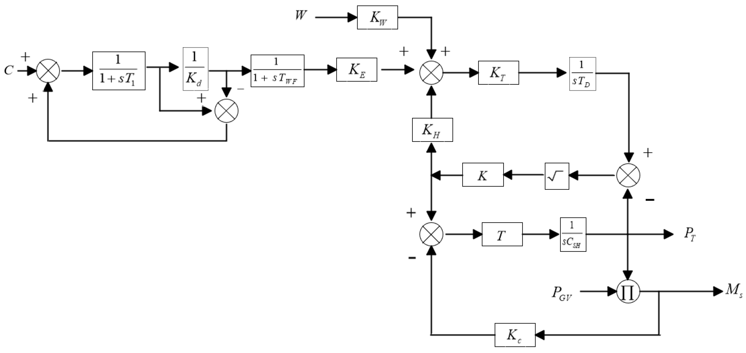
  • Integrating dynamic models of DC boilers and coal mills and accurately characterizing the coupling relationship between main steam pressure and flow rate improve simulation accuracy;
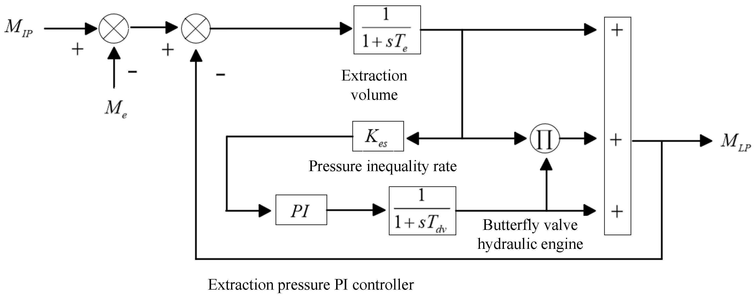
  • Propose a medium- and low-pressure connected pipeline extraction and heat module based on butterfly valve control. Through closed-loop transfer function and pressure inequality compensation mechanism, coupled with the medium-pressure regulating valve actuator and two-stage bypass system model, the cascade energy conversion efficiency between main steam and reheated steam was optimized, achieving coordinated regulation of exhaust flow rate and unit power;
  • Verify the dynamic characteristics of the model under frequency response, load regulation, and heat conditions by comparing parameter perturbation experiments with measured data.

2. Speed Control System Model and Single Reheat Steam Turbine

The core model of the steam turbine and its speed control system mainly consists of the governor, actuator, and steam turbine body. When the system detects the input command signal of speed deviation or power deviation, the speed controller calculates and processes it according to the preset control algorithm. Then, the governor outputs the control command to the actuator to drive the opening of the steam regulating valve to change, thus accurately regulating the steam flow entering the turbine. Under the real-time and precise action of the executing mechanism, the output mechanical power of the steam turbine can be dynamically adjusted to adapt to the demand of load fluctuations in the power system, ultimately maintaining the stability of the power system frequency.

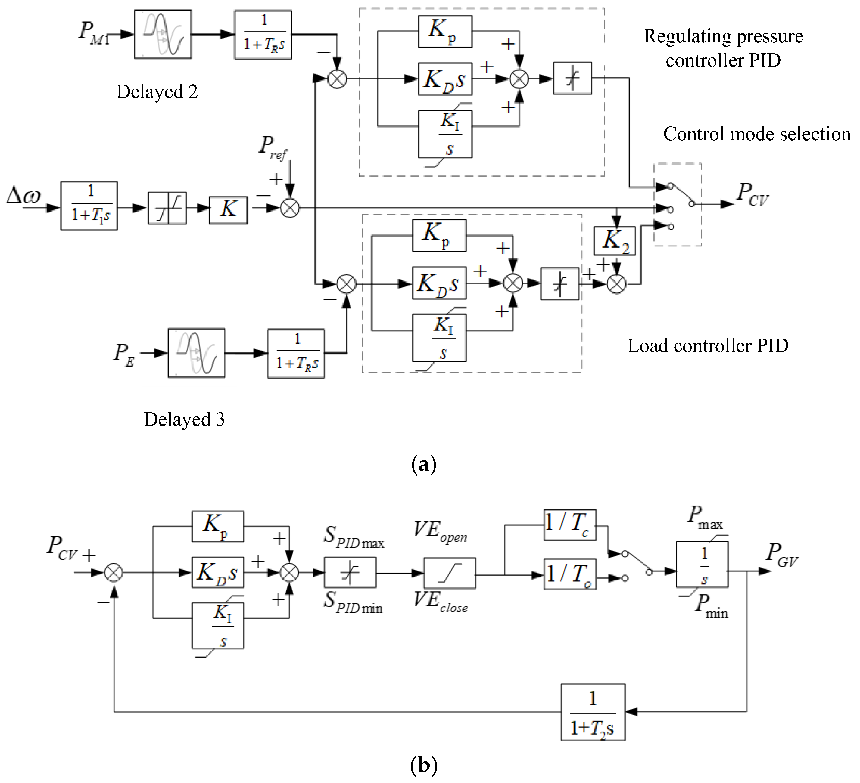
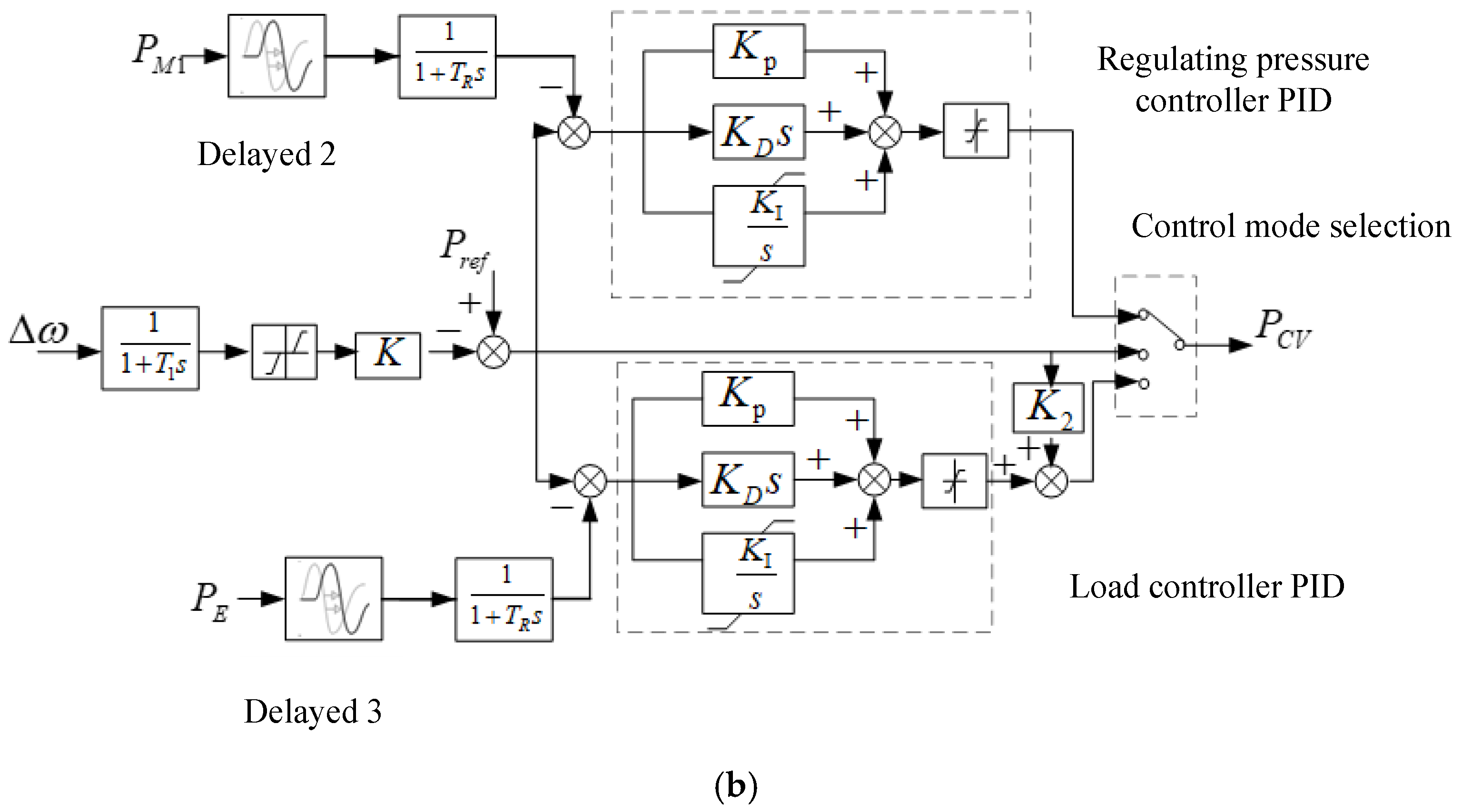
2.1. Speed Control System Model

The steam turbine control system widely used in current thermal power units is shown in Figure 1a. In the picture, Δ ω is the deviation between the speed and the speed reference value; K is the amplification factor of speed deviation; K 2 is the load control feedforward coefficient; K P , K I , and K D are PID proportional and derivative integral multiples; and P C V is the instruction signal for adjusting the door opening. When selecting the load control mode, the governor inputs the speed deviation Δ ω and power feedback signal P E P r e f , and outputs the valve opening command signal P C V .
As shown in Figure 1b, the core components of the actuator are the electro-hydraulic converter and the hydraulic execution unit. Its core function is to amplify the power and convert the energy form of the weak current control instructions issued by the regulating control system and drive the hydraulic execution unit to generate corresponding mechanical displacement outputs. The mechanical displacement directly acts on the steam regulating valve, and by precisely adjusting the valve opening, high-precision and dynamic closed-loop control of the steam flow entering the turbine is ultimately achieved.
In the picture, P G V is the signal for adjusting the door opening; S P I D max and S P I D min represent the upper and lower limits of the output of the comprehensive amplification stage, respectively; V E o p e n and V E c l o s e are the coefficients of overspeed opening and closing, respectively; T o and T c represent the time constants for the opening and closing of the hydraulic engine, respectively; and T 2 is the time constant of the stroke feedback loop of the hydraulic engine.

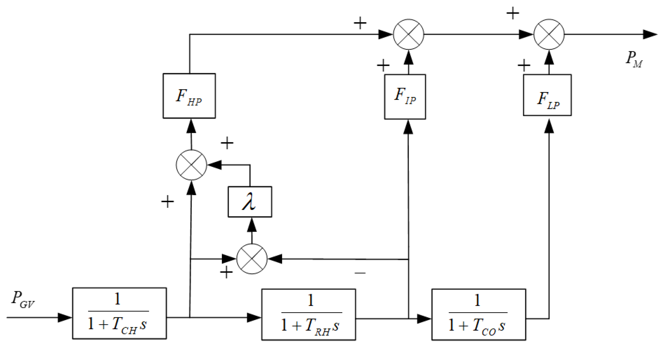
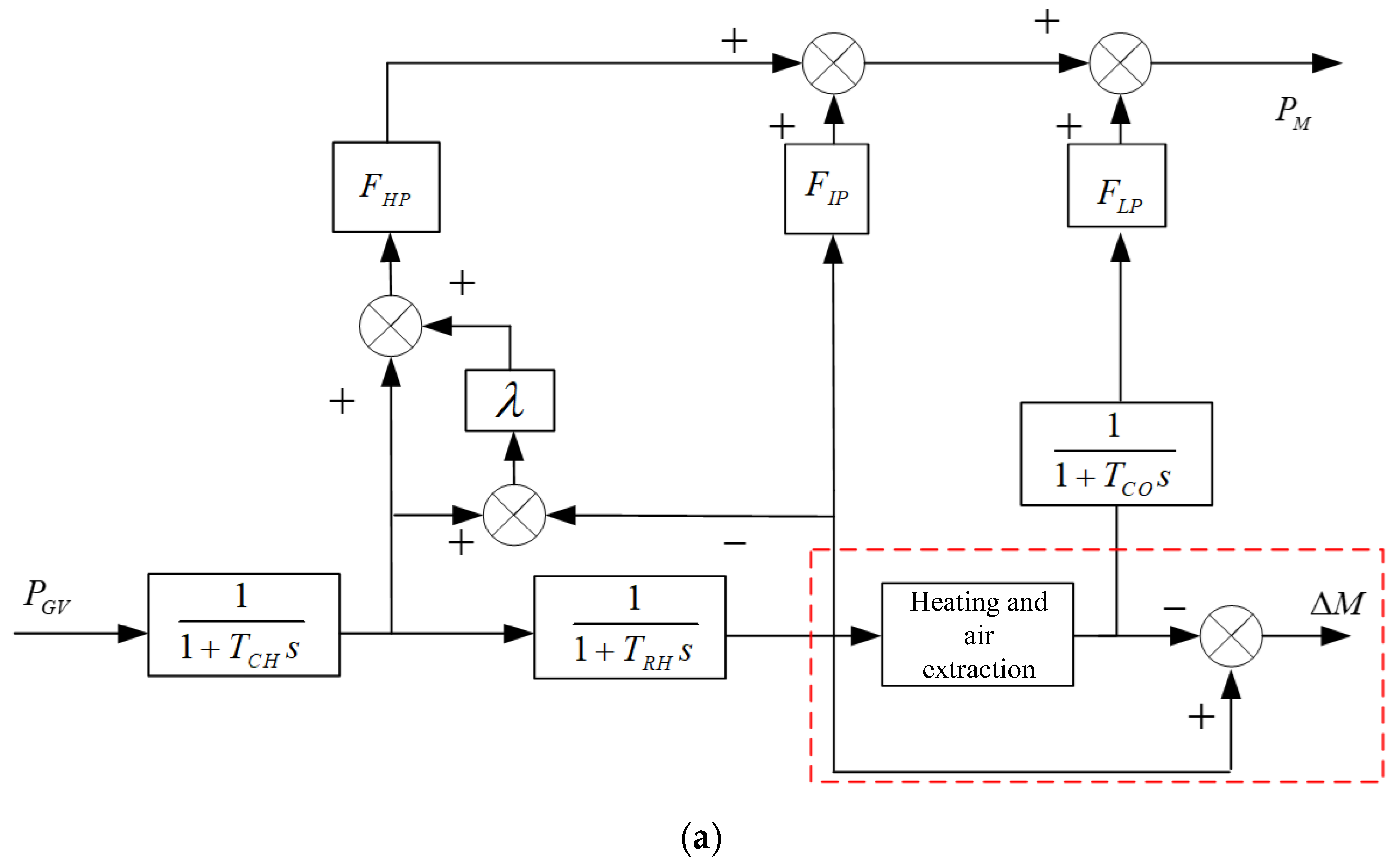
2.2. A Single Reheat Steam Turbine Model Considering the Influence of Boilers

Figure 2 shows the widely used model of a single reheat steam turbine. In the picture, P M is the mechanical power output of the steam turbine; F H P , F I P , and F L P are the proportional coefficients of the high-, medium-, and low-pressure cylinders of the steam turbine, respectively, where F H P + F I P + F L P = 1 ; T C H is the steam volume time constant; T R H is the time constant of the reheater; T C O is the cross-tube time constant; and λ is the natural overshoot coefficient of the high-pressure cylinder power. Refer to the industry standard proposed by the National Energy Administration, “Guide for Measurement and Modeling of Synchronous Generator Prime Mover and Regulating System Parameters” [18].
Currently, there is a general lack of in-depth understanding of the dynamic coupling effects of boiler systems in modeling research for single reheat steam turbines. However, actual operation has shown that the main steam pressure at the inlet of the steam turbine exhibits significant time-varying characteristics. When the opening of the regulating valve is activated, not only does the inlet pressure of the steam turbine generate dynamic response, but the outlet pressure of the boiler also fluctuates, forming a strong coupling dynamic process between the boiler and the steam turbine. In view of such dynamic coupling effects, in order to improve the simulation accuracy of the model under thermal conditions, this paper needs to systematically integrate the influence mechanism of the boiler model on the key parameters of the main steam.
To further enhance the fidelity of the model, the pulverizing system module has been extended in the DC boiler model, as shown in Figure 3, which includes a coal mill unit and a coal powder separator unit at its core. The coal mill can be characterized as a dynamic component of the fuel supply system with first-order inertia characteristics; the coal powder separator needs to be modeled based on the principle of gas–solid two-phase flow balance, accurately describing the process of coal powder fineness control and circulating material balance.
In the picture, W is the water supply amount; C is the coal feeding amount; M s is the main steam flow rate; P T is the main steam pressure; T 1 is the inertia time constant of powder production; K d uses cyclic coefficients; T W F is the delay time for fuel heat release; K E is the fuel heat release gain; K W is the gain of water supply flow rate; K T is the delay time of steam in the steam generator; K H is the steam flow gain at the outlet of the steam generator; T D is the time constant of the steam drum volume; K is the flow coefficient of the superheater and main steam pipeline; C S H is the volume time constant of the superheater; T is the delay time for steam to pass through the superheater; and K C is the feedback coefficient.

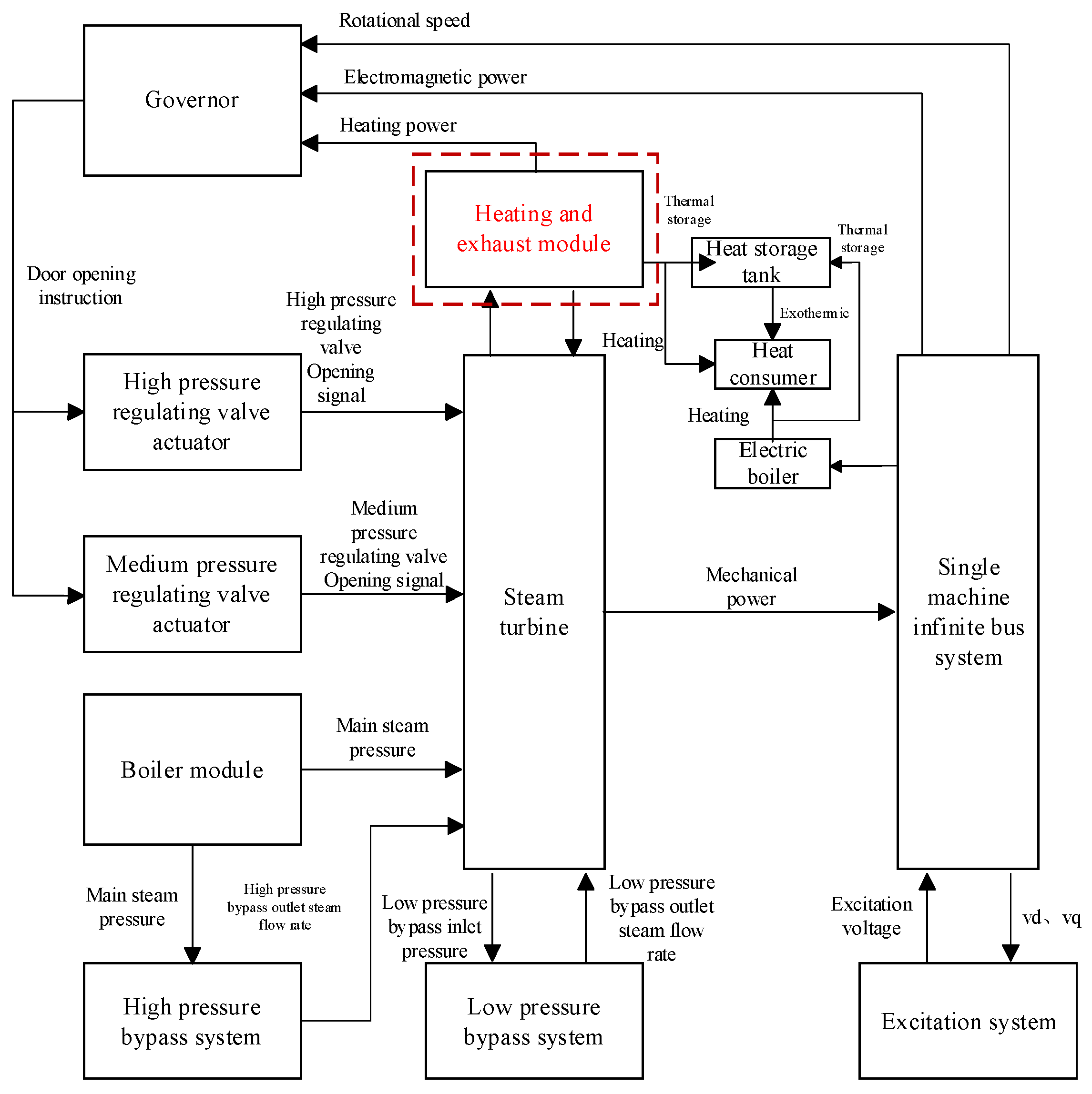
3. Model of Steam Turbine and Speed Control System Considering Heat Effects

To meet the modeling requirements of heat units participating in power system analysis, this paper constructs a dynamic module for heat extraction based on a steam turbine and an integrated model for a speed control system. In the current heat unit architecture, installing a regulating butterfly valve on the connecting pipe section from the intermediate pressure cylinder to the low-pressure cylinder is the core technical solution to achieve adjustable heat load. By accurately adjusting the butterfly valve opening in real-time, the steam diversion ratio between the medium- and low-pressure cylinders can be effectively controlled, achieving continuous adjustment of the heat extraction steam flow. This technological mechanism combines thermal energy spatiotemporal optimization allocation capability and system operational flexibility and dynamic response enhancement capability.

3.1. Heat and Exhaust Module Model

This study focuses on industrial heat scenarios, where the extracted heat steam is directly returned to the thermal system through a connected pipeline. Based on the characteristics of this process, the steam required for industrial heat load can be directly obtained from the exhaust port of the intermediate pressure cylinder. Based on the control mechanism of the butterfly valve, the waste heat recovery collaborative module shown in Figure 4 is constructed.
In the picture, M I P is the steam flow rate at the outlet of the intermediate pressure cylinder; M e is the exhaust heat flow rate; T e is the time constant of heat and exhaust volume; K e s is the unequal rate of extraction pressure; T d v is the time constant of the butterfly valve hydraulic motor; and M L P is the intake flow rate of the low-pressure cylinder.

3.2. Consider the Model of the Steam Turbine and Speed Control System for the Heat and Extraction Module

Based on the established waste heat recovery collaborative module, corresponding topology reconstruction is required for the steam turbine and its speed control system. The improved steam turbine structure is shown in Figure 5a, which integrates a heat and extraction module at the connecting pipeline of the medium-/low-pressure cylinder. In the figure, Δ M represents the steam flow extracted from the system for heat purposes.
The modification of the governor is shown in Figure 5b, where P e s is the heat load power value. When the unit does not consider heat, the load control method is adopted, and the electromagnetic power output by the system will be fed back to the governor. In the heat mode of this article, since Δ M will not return to the unit from the condenser, it is necessary to increase the power consumption of the heat load in the electromagnetic power feedback loop of the governor. This system uses per-unit values, so the values and trends of Δ M and P e s are the same.
Based on the previous text, build a dynamic simulation model in Simulink R2024a. In order to present the dynamic simulation model more clearly, the following block diagrams Figure 6 corresponding to the dynamic model have been drawn. Please refer to the Appendix A for detailed derivation formulas of each part of the model.

4. Simulation Verification of Steam Turbine and Speed Control System Affected by Heat Module

Based on the measured data of a 300 MW reasonable range heat unit in a power plant in Guangxi, the steady-state calculation model parameters of the turbine and speed control system are detailed in Table 1.
The established model is stimulated and analyzed using the model parameters in Table 1.

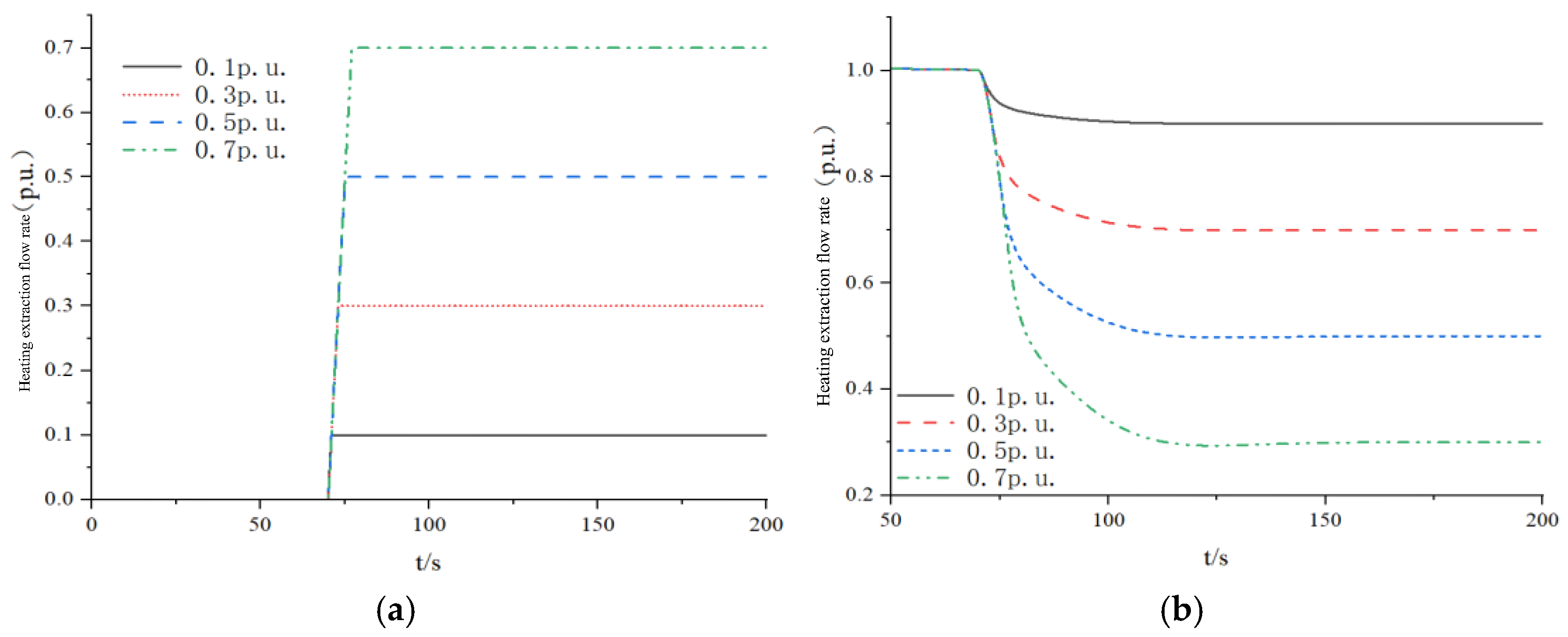
4.1. Analysis of Exhaust Flow Regulation for Heat Module

To verify the coupling mechanism of the heat module to the system, priority should be given to completing the effectiveness verification and accuracy verification process of the heat module model, as well as the analysis of the module’s effect on the dynamic characteristics of the unit output power.

4.2. Dynamic Follow Performance Analysis of Heat Modules

Set the input reference value for the heat extraction module to 1 (p.u.), and simulate continuous changes in extraction flow rate through input signals. The continuous monitoring module dynamically outputs responses. Given the hysteresis characteristics of thermal load response, a trapezoidal wave is used to simulate the dynamic process of steam extraction load. Apply trapezoidal wave commands of 0.1/0.3/0.5/0.7 (p.u.) at t = 70 s in Figure 7a to characterize different heat flow conditions. Based on the thermodynamic mechanism of the module, the sum of the steam flow rate at the inlet of the low-pressure cylinder and the extraction flow rate per unit must satisfy conservation constraints. As shown in Figure 7b, the output converges to the steady-state value at t = 150 s, verifying that the model has accurate reference input command tracking capability.

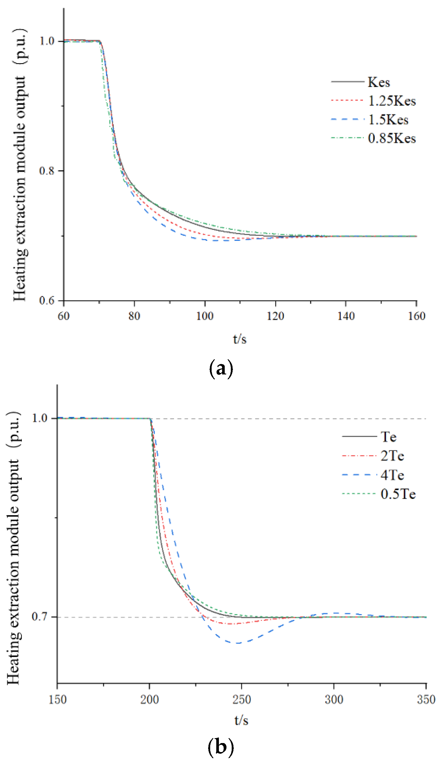
4.3. Analysis of Control Parameters of Heat Module Model

The key control parameters of the heat extraction module model mainly include unequal rate of pumping pressure, K e s ; time constant of heat extraction volume, T e ; and time constant of butterfly valve oil motor, T d v . The above key parameters directly determine the regulation quality of the heat extraction module. This article conducts multidimensional global perturbation experiments, and the test data is shown in Figure 8. The core control parameters of this module will map and inherit the benchmark tuning strategy of the executing mechanism of the speed control system.
According to the test results of Figure 8, the following conclusions can be drawn:
  • The inequality in pumping pressure rate K e s has a negligible effect on system overshoot. The larger K e s is, the worse the dynamic response performance is. The parameters of the butterfly valve oil motor T d v have a great influence on the overshoot of the system, and the larger the value, the greater the overshoot, and the longer the initial stability time of the system. The influence of the time constant of the heat extraction volume T e on the system is between K e s and T d v .The larger the dynamic response overshoot of the system T d v is, the more difficult the system is to stabilize.
  • The mapping inheritance strategy of the execution mechanism parameters of the speed control system can achieve global optimal control performance. At the level of system performance analysis, a two-layer evaluation framework needs to be established: single-parameter sensitivity analysis and comprehensive dynamic quality evaluation under multiphysics field coupling.

4.4. Analysis of the Output Mechanical Power of the Steam Turbine Considering the Heat Extraction Module

In the constructed simulation model, the mechanical power output end of the steam turbine is connected to a single machine infinite bus system, and the electromagnetic power feedback of the system is input to the speed control system, thus forming a closed-loop control loop. Under the set rated power conditions, the pumping airflow value is set to 0.10, 0.14, 0.18, and 0.22, and the pumping operation is performed at time t = 100 s. Figure 9a shows the influence of the change in pumping flow on the output mechanical power of the unit. The results show that the output mechanical power changes with the change in pumping flow, and introducing RMSE as a performance evaluation metric, the error was calculated to remain within 2%. Therefore, the free adjustment of thermal power has been verified. Further, under the condition of fixed pumping flow, the rated power values are set to 0.70, 0.62, 0.54, and 0.46, and the pumping operation is performed at time t = 100 s. Figure 9b shows the influence of rated power change on the output mechanical power of the unit. The results show that the change in power after pumping action is not affected by the adjustment of rated power; that is, the execution of pumping action does not change with the change in rated power.
Through in-depth analysis of the above content, the following conclusion can be drawn: in the simulation model, the heat extraction module exhibits excellent tracking performance, indicating that the selected control parameters have a high degree of rationality. After integrating the heat and extraction module into the steam turbine and its speed control system, the entire unit can accurately simulate the output power of the steam turbine, and the extraction operation can be executed normally according to the established requirements, ensuring the accuracy and reliability of the extraction results. From this, it can be seen that the simulation model constructed in this study can effectively map the dynamic behavior characteristics of the actual system, indicating that the heating unit model can freely adjust the output thermal power under fixed peak shaving depth, providing strong support for further systematic analysis of the operating status of the unit considering the influence of heat.

4.5. System Primary Frequency Modulation Simulation Analysis

Based on the above simulation results, it is possible to conduct a frequency modulation simulation test of the system in the coordinated control system (CCS) operating environment. During the experiment, the frequency reference was gradually adjusted from 3000 r/min to 3011 r/min, and the corresponding simulation results are shown in Figure 10a. In addition, if the frequency modulation reference is changed from 3000 r/min to 2989 r/min, the simulation results and measurement data curves at this time are shown in Figure 10b.
According to the chart analysis, when there is a fluctuation of ±11 r/min in the speed, the simulation results show that the frequency modulation dynamic process, overshoot, and adjustment time are consistent with the actual situation. Comparing the simulation results with the measured data, it can be seen that introducing RMSE as a performance evaluation metric, the error was calculated to remain within 3%, which fully confirms the high fidelity of the constructed simulation model in reproducing the dynamic characteristics of cogeneration units.

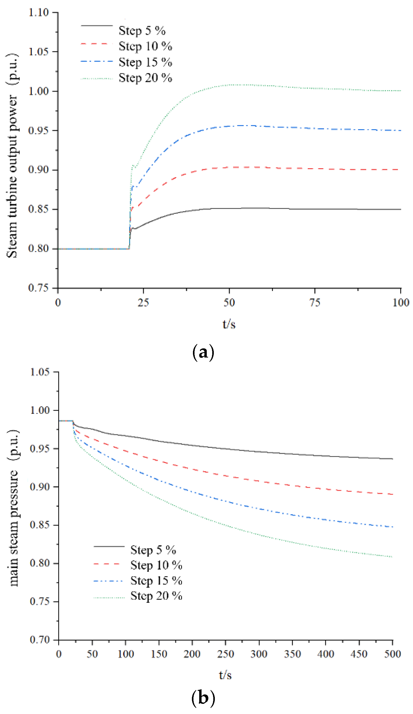
4.6. System Load Regulation Analysis

Based on the built model, the load step instructions of 5%, 10%, 15% and 20% are applied to the unit after 20 s of steady state. The main steam pressure and steam turbine output power under these four instructions are analyzed and compared. The simulation results are shown in Figure 10.
From the data analysis from different perspectives in Figure 11, it can be concluded that Figure 11a shows that the output power of the model monotonically increases with the load step instruction, and introducing RMSE as a performance evaluation metric, the error was calculated to remain within 2%, verifying the high fit between the model output and the actual operating conditions. Under the influence of the boiler module, the unit is subjected to load disturbances, which will correspondingly reduce the main steam pressure and decrease the main steam flow entering the turbine to ensure the normal operation of the system. Figure 11b further reveals that the main steam pressure drop rate of the boiler is positively correlated with the load command, can meet the requirements of power system analysis and calculation under continuous variable load conditions, and the error value is controlled within the engineering allowable range, which is highly consistent with the measured characteristics of the thermal system. The above two-dimensional quantitative evaluation results indicate that the coupled model of the steam turbine speed control system, including the heat module, in this paper can accurately reproduce the dynamic response characteristics of the cogeneration unit. Its inherent mechanism conforms to the physical laws of thermodynamic cycle and power frequency regulation and has reliability and applicability in engineering applications such as power system stability analysis and primary frequency regulation performance optimization.

5. Conclusions

The simulation model of a single reheat steam turbine and its speed control system, which takes into account the heat effect, established in this article, can accurately reproduce the operation process of the heat unit under extraction heat conditions. Through in-depth research on its performance indicators and parameters, the accuracy of the heat module and exhaust module has been fully verified. This conclusion provides solid and strong support for the reliability of the model in simulating actual heat units.
In further research, this model will be compared with multiple other models to demonstrate its advantages. To emphasize the dynamic characteristics of the developed model in frequency fluctuation response and load change response, the simulation results will also be compared with the experimental results of power plant equipment research, as well as with the actual frequency adjustment process in detail. In addition, the performance of the model under fast transients and sudden load shedding will also be discussed, which will ensure the safety of the model under extreme operating conditions. Through the comparative analysis in summary, it can be strongly demonstrated that the constructed model has the ability to be effective and accurate, laying a solid foundation for the promotion and application of the model in the field of power system dynamic simulation.

Author Contributions

Conceptualization, L.W. and H.H.; methodology, J.X.; formal analysis, L.W., H.H. and J.X.; writing—original draft preparation, L.W., H.H. and J.X. All authors have read and agreed to the published version of the manuscript.

Funding

Science and Technology Project of Guangxi Power Grid Co., Ltd. (No. GXKJXM20230090).

Data Availability Statement

The original contributions presented in this study are included in the article. Further inquiries can be directed to the corresponding author.

Conflicts of Interest

Authors Libin Wen, Hong Hu, and Jinji Xi were employed by the Electric Power Research Institute of Guangxi Power Grid Co., Ltd. Authors Libin Wen and Jinji Xi were employed by Guangxi Key Laboratory of Intelligent Control and Maintenance of Power Equipment. Author Hong Hu was employed by the School of Electrical Engineering and Automation, Wuhan University. All of the authors declare that the research was conducted in the absence of any commercial or financial relationships that could be construed as a potential conflict of interest.

Appendix A

During the operation of a steam turbine, according to the law of conservation of mass, the difference between the gas flow rate entering the system and the gas flow rate leaving the system per unit time is the product of the internal volume of the system and the change in gas density, as shown in Equation (A1).
q i n q o u t = V m d ρ g d t .
In the formula, q i n represents the gas flow rate entering the system; q o u t represents the gas flow rate leaving the system; V m represents the internal volume of the system; and ρ g represents the gas density.
According to the valve opening and gas flow characteristics, the gas flow entering the system q i n can be equivalently related to the valve opening P G V as follows:
q i n = k G V P G V .
In the formula, k G V is the static amplification factor of the regulating valve, and P G V is the opening degree of the regulating valve. Meanwhile, the gas flow rate leaving the system and the internal pressure of the system can also be equivalently expressed as follows:
q o u t = k p p m .
In the formula, k p is the static amplification factor of the internal pressure of the system, and p m is the internal pressure of the system.
By substituting Equations (A2) and (A3) into Equation (A1), we obtain the following:
k G V P G V k p p m = V m d ρ g d t .
Based on the law of mass conservation in the flow process of gas, the state of gas changes according to a variable process, and there is the following formula:
k G V P G V k p p m = V m d ρ g d t · ρ g N p m .
In the formula, N is the state index of the variable process.
Furthermore, for this nonlinear system, it can be approximated as a linear system near the equilibrium point. Taylor expansion is used to approximate the nonlinear equation in a first-order manner, ignoring higher-order small quantities, and ultimately obtaining a linearized state equation. Assuming the equilibrium point of the key parameters in Equation (A5) is ρ g 0 , P G V 0 , and p m 0 , the following equation can be obtained:
k G V ( Δ P G V + P G V 0 ) k p ( Δ p m + p m 0 ) = V m d ρ g d t · ( Δ ρ g + ρ g 0 ) N ( Δ p m + p m 0 ) .
In the formula, Δ P G V is the small increment at the balance point of the adjustable door opening; Δ p m is a small increment at the pressure equilibrium point within the system; and Δ ρ g is a small increment at the equilibrium point of gas density.
Due to the negligible relative equilibrium point values of small increments Δ ρ g and Δ p m , Equation (A6) can be further simplified as follows:
k G V Δ P G V k p Δ p m = V m d ρ g d t · ρ g 0 N p m 0 .
Furthermore, by performing a Laplace transform on Equation (A7), the transfer function of the system gas volume can be obtained,
S p m ( s ) S P G V ( s ) = 1 1 + V m ρ g 0 N s = 1 1 + T s .
In the formula, T is the system volume time constant.
The extraction volume of the heating extraction module meets the requirements,
M I P M e = M L P .
T e d B d t + B = M I P M e .
In the formula, T e is the time constant of heating extraction volume; B is the output of heating extraction volume, and M I P is the steam flow rate at the outlet of the intermediate pressure cylinder; M e is the extraction and heating flow rate; and M L P is the intake flow rate of the low-pressure cylinder.
According to the working principle of the extraction module, the gas entering the butterfly valve will be affected by uneven pressure:
C = K e s · B .
In the formula, C is the heating extraction volume output affected by pressure inequality rate; and K e s is the pressure inequality coefficient.
According to the derivation of the transfer function of the hydraulic servo motor in the previous text, it can be concluded that the butterfly valve hydraulic servo motor satisfies:
T d v d M e d t + M e = C .
In the formula, T d v is the time constant of the butterfly valve hydraulic motor.
By organizing Formulas (A9)–(A12) and performing Laplace transform, we obtain the following:
M e ( s ) = K e s · B ( s ) 1 + s T d v .
B ( s ) = M I P ( s ) M e ( s ) 1 + s T e .
After combining Equations (A13) and (A14), the closed-loop transfer function can be obtained as follows:
M e ( s ) M I P ( s ) = K e s ( 1 + s T d v ) ( 1 + s T e ) + K e s

References

  1. Yan, S.; Zeng, D.L.; Liu, J.Z.; Liang, Q.J. A Simplified Non-linear Model of a Once-through Boiler-turbine Unit and Its Application. Chin. J. Electr. Eng. 2012, 32, 126–134. [Google Scholar] [CrossRef]
  2. Su, Z. Modeling of Boiler Steam Turbine Based on Adaptive Neuro-Fuzzy Inference System. Master’s Thesis, North China Electric Power University, Beijing, China, 2020. [Google Scholar] [CrossRef]
  3. Yan, P. Research on Multiple Model Nonlinear Decoupling Control Method for 660 MW Large Thermal Power Units. Master’s Thesis, Shenyang Agricultural University, Shenyang, China, 2023. [Google Scholar] [CrossRef]
  4. Wang, Y.; Jiang, L.; Wang, Y. Research on modeling of cogeneration units based on digital twin technology. Therm. Power Gener. 2023, 52, 106–114. [Google Scholar] [CrossRef]
  5. Wu, J. Units Research on Modeling and Predictive Control of Multiple Cogeneration Units. Master’s Thesis, North China Electric Power University, Beijing, China, 2023. [Google Scholar] [CrossRef]
  6. Zhang, G. Research on Flexible Operation Characteristics and Control of Combined Heat and Power Units. Ph.D. Thesis, North China Electric Power University, Beijing, China, 2022. [Google Scholar] [CrossRef]
  7. Liu, Z. Study of Operation Characteristics of Gas-Steam in Combination Cycle with chp Unit Coupled in Combination with Compression Heat Pump. Master’s Thesis, Southeast University, Nanjing, China, 2022. [Google Scholar] [CrossRef]
  8. Hou, G.; Ye, L.; Huang, T.; Huang, C. Intelligent modeling of combined heat and power unit under full operating conditions via improved cross former and precise sparrow search algorithm. Energy 2024, 308, 132879. [Google Scholar] [CrossRef]
  9. Ma, Y.; Wang, H.; Hong, F.; Yang, J.; Chen, Z.; Cui, H.; Feng, J. Modeling and optimization of combined heat and power with power-to-gas and carbon capture system in integrated energy system. Energy 2021, 236, 121392. [Google Scholar] [CrossRef]
  10. Zhang, M.; Wu, Q.; Wen, J.; Lin, Z.; Fang, F.; Chen, Q. Optimal operation of integrated electricity and heat system: A review of modeling and solution methods. Renew. Sustain. Energy Rev. 2021, 135, 110098. [Google Scholar] [CrossRef]
  11. Koch, K.; Alt, B.; Gaderer, M. Dynamic Modeling of a Decarbonized District Heating System with CHP Plants in Electricity-Based Mode of Operation. Energies 2020, 13, 4134. [Google Scholar] [CrossRef]
  12. Li, L.; Liu, X. Control Strategy Optimization for Thermal Power Unit Adapted to Deep Peak Shaving for Large-Scale New Energy Source Integration. China Electr. Power 2020, 53, 155–161. [Google Scholar] [CrossRef]
  13. Wu, H.; Wang, F.; Yuan, M.; Wang, X.; Lin, C.; Xu, J. Application Study of Micro -output Technology for Low- pressure Cylinder of 300 MW Heating Unit. Valve 2024, 1397–1400. [Google Scholar] [CrossRef]
  14. Zhou, X. Modeling and Control of Supercritical Heat and Power Cogeneration Unit. Master’s Thesis, North China Electric Power University, Beijing, China, 2022. [Google Scholar] [CrossRef]
  15. Zhang, X.; Yang, X.; Xin, G.; Liu, K.; Cui, F.; Zhao, Z. Experimental study on deep peak regulation operation of coal-fired thermal power unit. Clean Coal Technol. 2022, 28, 144–150. [Google Scholar] [CrossRef]
  16. Wang, L. Flexibility and Performance Analysis of Integrated Electric Boiler Heating Unit Operation. Energy Res. Util. 2024, 34–39. [Google Scholar] [CrossRef]
  17. Liu, D.; Ma, H.; Wang, B.; Gao, W.; Wang, J.; Yan, B. Operation Optimization of Regional lntegrated Energy system with CCHP and Energy Storage System. Power Syst. Autom. 2018, 42, 113–120+141. [Google Scholar] [CrossRef]
  18. DL/T 1235-2019; Guide for Measurement and Modeling of Synchronous Generator Prime Mover and Regulating System Parameters. National Energy Administration (NEA): Beijing, China, 2019.
Figure 1. Speed control system model. (a) Regulating control system; (b) Execution mechanism model.
Processes 13 02445 g001
Figure 2. Single reheat steam turbine model.
Processes 13 02445 g002
Figure 3. Model of DC boiler considering coal mill.
Processes 13 02445 g003
Figure 4. Heat and exhaust module model.
Processes 13 02445 g004
Figure 5. Model considering heat and exhaust modules. (a) Consider a DC boiler model with heat and exhaust modules; (b) Consider the governor model of the heat and exhaust module.
Processes 13 02445 g005aProcesses 13 02445 g005b
Figure 6. Block diagram of dynamic simulation model.
Processes 13 02445 g006
Figure 7. Performance analysis of heat and exhaust module model following. (a) Heat extraction flow rate per unit; (b) Output value of heat and exhaust module.
Processes 13 02445 g007
Figure 8. Perturbation test of control parameters of heat extraction module. (a) Unequal rate perturbation test of pumping pressure; (b) Perturbation test of pumping volume time constant; (c) Perturbation test of time constant of butterfly valve oil motor.
Processes 13 02445 g008aProcesses 13 02445 g008b
Figure 9. Considering the output power of the steam turbine of the heat extraction module. (a) Output power of steam turbine under different extraction flow; (b) Output power of steam turbine under different rated power.
Processes 13 02445 g009
Figure 10. Unit primary frequency modulation output power measured data and simulation results. (a) Increase in speed; (b) Revolution drop.
Processes 13 02445 g010
Figure 11. Heat unit load regulation analysis. (a) Output power of steam turbine at different power step; (b) Main steam pressure at different power step.
Processes 13 02445 g011
Table 1. Model parameters of steam turbine and speed control system.
ParameterNumerical ValueParameterNumerical Value
Steam volume time constant T C H 0.22Output upper limit of amplification stage S P I D max 10.0
High-pressure cylinder power proportional coefficient F H P 0.3005Output lower limit of amplification stage S P I D min −10.0
Proportional coefficient of intermediate pressure cylinder power F I P 0.2801Overspeed opening coefficient V E o p e n 0.1619
Low-pressure cylinder power proportional coefficient F L P 0.4194Oil engine opening time constant V E c l o s e −0.2394
Reheater time constant T R H 10.0Oil engine opening time constant T o 6.744
Cross-tube time constant T C O 2.30Closing time constant of hydraulic actuator T c 4.521
Kp, Ki, Kd of the governor model0.1, 0.06667, 0Time constant of stroke feedback loop for hydraulic engine T 2 0.02
Natural overshoot coefficient of high-pressure cylinder power λ 0.6006\\
Disclaimer/Publisher’s Note: The statements, opinions and data contained in all publications are solely those of the individual author(s) and contributor(s) and not of MDPI and/or the editor(s). MDPI and/or the editor(s) disclaim responsibility for any injury to people or property resulting from any ideas, methods, instructions or products referred to in the content.

