Abstract
This study proposes a polygeneration system that integrates an absorption cooling system, a heat transformer, and an organic Rankine cycle for the simultaneous production of power, cooling, and freshwater—the former operating with a water/lithium bromide mixture while the organic Rankine cycle operates with R123. The system was simulated at temperatures between 100 °C and 150 °C and with heat supply capacities that a geothermal field in Nayarit, Mexico, could provide. A parametric analysis was conducted by developing a mathematical model using the Engineering Equation Solver software. The geothermal source temperatures, ambient temperatures, and mass ratios were varied to determine the power, cooling load, freshwater production, and energy utilization factor under different operating conditions. The results showed that the system could produce up to 13 kW of power, 100 kW of cooling, and 50 L per hour at a heat source temperature of 150 °C. The energy utilization factor varied from 0.32 to 0.43, which means that up to 43% of the energy supplied to the system could be utilized to produce cooling, freshwater, or power.
1. Introduction
Modern energy systems are primarily focused on either generating electrical power or providing cooling, which is essential for applications such as low-temperature product preservation and space conditioning. The importance of these systems lies in the fact that both electricity and cooling are fundamental needs across all sectors of society. However, in most cases, producing these energy services through conventional methods is associated with environmental impacts, either directly or indirectly. To mitigate these effects, various strategies have been implemented, including the integration of clean energy sources, the design of energy-efficient systems, and the use of environmentally friendly working fluids. One particularly effective approach to enhancing energy system efficiency is the development of polygeneration systems (PgSs), which simultaneously produce multiple useful energy outputs. This integrated approach allows for a more efficient use of resources compared to traditional single-output energy conversion systems. In parallel, water security has become a pressing global concern, as many regions face severe water scarcity [1]. This issue is exacerbated by the overexploitation of freshwater resources and the growing global population, whose quality of life is closely linked to the availability of clean water. In this context, designing and developing efficient PgSs that are capable of producing electricity, cooling, and freshwater (i.e., desalination) offers a promising solution to addressing these interrelated challenges. The following paragraphs highlight some of the most relevant research efforts focused on PgSs that combine power generation, cooling, and water desalination.
1.1. Integration of Gas Turbine Cycles and Heat Recovery in the PgS
Power production using geothermal energy in binary plants has been widely reported for a long time [2,3], and even more efficient geothermal power plants have been reported which are based on flash-combined cycles, which improve power production and plant efficiency [4,5]. Nevertheless, these geothermal plants only have the purpose of producing power. Polygeneration systems (PgSs) for the simultaneous production of power, heating, cooling, or other products are gaining the interest of the scientific community due to their higher combined thermal and power efficiencies. Additionally, PgSs can operate not only with renewable energies such as geothermal or solar but also with industrial waste heat or a combination of diverse energies, which makes them more versatile.
A typical way to generate power in a PgS is the integration of a gas turbine (GT) in the cycle. Anvari et al. [6] analyzed a PgS that integrated a GT, an organic Rankine cycle (ORC), a double-effect absorption cooling system (ACS), and a desalination system coupled with a single-effect absorption heat transformer (AHT). This system can produce up to 30.5 MW of power, 40.8 MW of heating, 1 MW of cooling, and 0.364 kg/s of desalinated water with total CO2 emissions of 0.163 kg/kWh. On the other hand, a new electricity and freshwater generation system was proposed by Hamrang et al. [7]. The system is based on the use of the integrated gasification and GT cycle as the main system, and a steam Rankine cycle and multi-effect desalination (MED) system as the waste heat recovery units. It was found that, for the base case, the performance metrics were evaluated as follows: , an exergy efficiency of 46.22%, a sum unit cost of the product of 14.07 $/GJ, and a mass flow rate of freshwater of 11.7 kg/s.
Lei et al. [8] introduced a novel PgS integrated with a GT cycle that was designed to produce power, freshwater, hydrogen, oxygen, chilled water, and domestic hot water while minimizing the irreversibility and environmental impact of the process. The system incorporates a water desalination unit, organic and Rankine cycles, and a hydrogen generation unit. The process was simulated using Aspen HYSYS software, and a comprehensive 4E analysis (energy, exergy, economic, and environmental) was conducted. The system achieved energy and exergy efficiencies of 57.81% and 63.47%, respectively, with the ORC subsystem showing the highest efficiency among power generation units (68.73%). Javadpour et al. [9] performed a techno-economic investigation of the integration of a multiple-effect desalination/thermal vapor compression (MED/TVC) system and a reverse osmosis (RO) system into a GT power cycle. Energy and economic analyses were done for three configurations of GT/MED-TVC, GT/RO, and GT/MED-TVC/RO. It was found that increasing the compressor inlet air temperature causes an enhancement in the outlet gas temperature for both GT/MED-TVC and GT/MED-TVC/RO systems. A trigeneration system designed for marine applications was analyzed by Cao et al. [10]. The system utilized waste heat to generate electricity, cooling, and freshwater simultaneously. The proposed system comprises a regenerative ORC, a single-effect ACS, and a humidification-dehumidification (H-Dh) desalination unit. Simulation results indicated that the system’s optimal performance yields a net electrical output of 783.9 kW, a cooling capacity of 959.8 kW, and a freshwater production rate of 98.1 m3/day, with energy and exergy efficiencies of 58.4% and 43.0%, respectively, and the total cost per unit of exergy output calculated at 0.1494 $/kWh. A trigeneration system that integrated a low-grade heat source Kalina cycle to drive an NH3-H2O ACS, a hydrocarbon-based ORC, and an RO desalination unit was proposed by Safder et al. [11]. The system configuration efficiently utilizes low-temperature thermal energy to produce electricity, cooling, and freshwater simultaneously. Simulation results demonstrated that the system could deliver 1725 kW of electrical power, 665 kW of cooling capacity, and 3.42 m3/h of freshwater, highlighting its potential for efficient multi-output energy conversion.
Given that the use of gas turbines typically involves fossil fuels (whose environmental impact is a significant drawback), several studies have focused on exploring alternative fuels, such as biogas, biomass, and even methane produced through reforming processes. The following section describes these research efforts in more detail.
The exergoeconomic optimization of a novel biogas-driven trigeneration system designed to produce power, cooling, and freshwater was performed by Gholizadeh et al. [12]. The system integrates a GT cycle, an ORC coupled with an ejector refrigeration cycle, and a H-Dh desalination unit. Five working fluids were assessed for the ORC, with toluene being identified as the optimal choice due to its superior refrigeration load and highest trigeneration-based gain/output ratio (GOR). The optimization results demonstrated notable performance enhancements, including increases of up to 2.58% in net electricity generation, 22.69% in refrigeration load, 14.04% in GOR, and 13.26% in exergy efficiency. Simultaneously, the unit cost of trigeneration was reduced by 6.71%, which indicated both thermodynamic and economic improvements. Zhang et al. [13] propose a novel PgS that utilizes waste energy from a regenerative GT cycle to produce electricity, hydrogen, freshwater, and hot steam. The system integrates a partial cooling supercritical CO2 Brayton cycle, thermoelectric generators, a proton exchange membrane electrolysis (PEME) unit, and a reverse osmosis desalination unit. Multi-objective optimization was performed to compare the system’s performance using biogas and pure methane as fuels. It was found that biogas is economically superior, reducing the economic cost rate by 32.5% and the unit cost of polygeneration by 32.4% compared to methane. The exergy efficiency of the system is similar for both fuels, with biogas achieving 40.45% and methane 40.72%. A novel trigeneration system configuration was analyzed for the simultaneous production of power, cooling, and freshwater by Soares et al. [14]. The system comprised biogas-powered microturbines, a LiBr/H2O ACS, and an H-Dh desalination system. Performance optimization was conducted based on first-law thermodynamic analysis. Under optimal conditions, the system achieved outputs of 104.4 kW of electricity, 12 kW of cooling, and 0.1231 kg/s of freshwater, corresponding to an energy utilization factor (EUF) of 1.024. These results demonstrate the system’s effective use of renewable biogas for integrated energy and water production.
A novel approach to efficiently produce electricity, hot water, chilled water, freshwater, and methanol was proposed by Houran et al. [15]. This system comprises a steam methane reforming process, a Kalina cycle, a multi-effect distillation (MED) unit, a methanol synthesis unit, two organic Rankine cycles (ORC), and two ammonia Rankine cycles. The findings reveal that the newly devised process exhibits energy and exergy efficiencies of 47.55% and 50.58%, respectively, while the total unit cost of products amounts to 7.69 $/GJ. A small-scale, renewable, heat-driven PgS was proposed by Ayou et al. [16] to simultaneously provide chilled water for space cooling, electricity, and seawater desalination. The system integrates a power-refrigeration cycle with evacuated flat plate solar collectors and a biomass-fired backup boiler, which ensures a continuous thermal energy supply. For the desalination process, both permeate gap membrane distillation (PGMD) and conductive gap membrane distillation (CGMD) modules were considered. In the base-case configuration using CGMD modules, the system produced 41.4 m3/day of desalinated water, delivered 130 kW of cooling capacity, and generated a net electrical output of 6.4 kW. Notably, the use of CGMD reduced the required membrane surface area by 53% compared to PGMD, demonstrating a significant improvement in system compactness and efficiency. Dai and Yin [17] proposed a novel PgS that integrates a Brayton GT cycle with steam methane reforming, a PEME, and a MED unit for the simultaneous production of power, cooling, freshwater, and hydrogen using methane as fuel. The system achieved a net output power of 16,251.8 kW, a cooling load of 15,905.0 kW, a freshwater production rate of 3.891 kg/s, and a hydrogen generation rate of 0.284 kg/h, with energy and exergy efficiencies of 60.48% and 32.55%, respectively. Optimization improved the system’s energy efficiency to 61.62%, reduced the payback period to 0.40 years, and reduced the sum unit cost of the product (SUCP) to 3.99 $/GJ.
1.2. Poligeneration Systems Driven with Renewable Energies
Over the past few decades, power generation systems (PgSs) powered by renewable energy have experienced substantial development driven by rapid technological advancements and the implementation of practical methodologies. The adoption of these systems has made multi-output production from geothermal or solar energy feasible, enabling the generation of electricity, heating, cooling, hydrogen, and desalinated water. Regarding this research, several relevant works are presented next.
Azizi et al. [18] presented a comprehensive review of PgSs that utilize geothermal energy combined with other forms of renewable energy. The study indicates that, in the vast majority of cases, geothermal energy is integrated with another renewable source to produce both heating and cooling. Approximately 10% of such systems are dedicated to electricity generation. Desalinated water and hydrogen production are regarded as auxiliary outputs within these systems. Another analysis [19] examines freshwater production through the use of PgSs powered by renewable energy sources, with a particular focus on various desalination technologies. The authors highlight the significance of energy and exergy analyses, pointing out the need for further advancements in multi-objective optimization, accurate modeling, and uncertainty analysis to improve the performance of renewable-based PgSs in the context of evolving policies and technological development. A more recent review [20] established the desalination of geothermal brine as a source of potable water for arid and remote regions. It highlights that advanced geothermal configurations (such as regenerative and two-stage ORC systems), along with enhanced absorption chiller designs and part-load operation models, can significantly improve the overall performance of multigeneration plants.
Pastor-Martinez et al. [21] introduced a PgS for the simultaneous production of heating, cooling, and power by combining an ORC and an ACS. This system was modeled within the framework of the first and second laws of thermodynamics. Various cascade configuration arrangements were analyzed for comparative purposes, and it was found that the energy and exergy efficiencies of geothermal-based PgSs are strongly dependent on the operating temperature range (80–110 °C and 110–150 °C). Furthermore, the positioning of key components plays a significant role in the overall system performance. A similar work focusing on performance analysis based on the first and second laws of thermodynamics is reported by Calise et al. [22]. This research incorporates desalination as an additional output and combines medium-enthalpy geothermal energy with solar energy to evaluate the performance of systems in both summer and winter conditions. Other research by this group [23,24,25] is focused on first-and second-law analyses of PgSs based on geothermal energy, either alone or in combination with solar energy, that are designed produce electricity, freshwater, and/or thermal services such as heating or cooling. On the other hand, the system proposed by Musharavati et al. [26] relies solely on geothermal energy and integrates a PEM electrolyzer, a reverse osmosis desalination unit, a Kalina cycle, and a thermoelectric module within a polygeneration scheme. It produces both fresh and hot water as outputs. A tri-objective optimization was carried out to determine the optimal operating conditions of the system, and also to identify the components with the highest exergy destruction rates.
Ghiasirad et al. [27] introduced a novel system that used geothermal energy to generate power, cooling, heating, and freshwater. The system’s main components include an AHT, a H-Dh desalination unit, an ORC, an ACS, and a space heating unit. Through different analyses (energy, exergy, and exergoeconomic), it was found that the system can generate up to 78.4 kW of net power, 92.1 m3/day of freshwater, 6.25 MW of heating, and 4.99 MW of cooling. Shi and Shang [28] introduced a novel hybrid multigeneration system that integrates solar and geothermal energy sources to produce power, hydrogen, cooling, and freshwater simultaneously. The system leverages methanol-steam reforming and modified ACS, H-Dh, and MED processes. The base design achieved an exergy efficiency of 49.11% and a unit product cost of $32.08/GJ, producing 146.16 kW of power, 4.5 kg/s of freshwater, 0.023 kg/s of hydrogen, and 119.61 kW of cooling. A multigeneration system for cooling, heating, power, and freshwater using a geothermal heat source was analyzed by Ghaebi et al. [29]. The system integrates a Kalina cycle, an ACS, a H-Dh desalination system, and a domestic water heater, and it was found that the optimal thermal efficiency, exergy efficiency, and total SUCP were 94.84%, 47.89%, and 89.95 $/GJ, respectively. Yao et al. [30] proposed a novel hybridization method for a flash-binary geothermal cycle, a GT cycle, an organic flash cycle, and a MED subsystem to allow the efficient cogeneration of electricity and freshwater. For the base case, the system reached an exergy efficiency of 37.45% with a power generation capacity of 19.02 MW, a total freshwater rate of 38.69 kg/s, and a total profit and payback period of 60.07 $M and 3.75 years. Further, the triple-objective optimization showed that the exergy efficiency, profitability, and payback period of 38.41%, 62.71 M$, and 3.26 years, respectively, were achieved.
An integrated PgS combining a concentrated solar power (CSP) system with an NH3-H2O ACS and a MED desalination process was proposed by Mehrpooya et al. [31]. The system is designed to generate electricity, refrigeration, and freshwater simultaneously. Parabolic dish collectors supply the system with 21,030 kW of thermal energy, from which 4632 kW is converted into electricity. Additionally, the system produces 820.8 kW of cooling and 22.79 kg/s of freshwater. The overall exergy efficiency of the system is 66.05%, while the net thermal efficiency reaches 80.70%, which demonstrates the high potential of solar-driven trigeneration for sustainable energy and water production. The exergy and thermo-economic performance of a Rankine cycle coupled with a MED plant powered by solar molten salts was analyzed by Mata-Torres et al. [32]. The research evaluates the impact of part-load operation, the ambient temperature, the MED plant size, and the plant altitude on the costs and efficiency of electricity and freshwater production. A detailed model with high disaggregation was developed to assess exergy destruction, cost allocation, and operational performance. The study highlights the importance of operating these types of plants at full load to minimize costs and maximize efficiency. It was also noted that larger MED plants are optimal for cost reduction, but that altitude and part-load operation significantly impact water costs. Chaturvedi et al. [33] carried out an in-depth parametric study coupled with a bi-objective optimization to identify the optimal operating conditions of PgSs. A single-flash binary geothermal power unit with multiple subsystems was integrated into the plant. Parametric analysis showed that variations in the geothermal water mass flow rate had the greatest impact on the net power output and purified water production.
Shamsi et al. [34] conducted a multicriteria evaluation of a PgS that includes green ammonia production; such a system comprises an ORC subsystem, an air separation unit, a PEME for clean hydrogen generation, and an ammonia synthesis unit. The exergy analysis showed a fair distribution of irreversibility among the subsystems, while the sensitivity analysis highlighted the operative pressure and flow rate as key design parameters. The integration of a MED system and an ORC for the simultaneous production of freshwater and electrical energy using low-temperature sources was proposed by Aguilar-Jiménez et al. [35]. In this system, the thermal energy required for the system’s operation is supplied in the MED’s evaporator, while the ORC utilizes a fraction of the condensation heat of the steam produced in the first stage of the MED. The results show that the MED/ORC energetic integration study benefits the final production of desalinated water. The integration of a MED-TVC unit into a Rankine cycle power block was analyzed by Ortega-Delgado et al. [36], who focused on optimizing the desalination efficiency and minimizing costs of PgSs. The study analyzed the influence of motive and suction steam pressures on key performance metrics such as GOR, distillate production, and specific heat transfer area, providing a simulation tool to optimize MED-TVC integration into power blocks, which allows balancing water and electricity production based on demand profiles.
The above literature review reveals a wide range of studies addressing PgSs from various perspectives, including modifications to gas power cycles, waste heat recovery, the integration of biofuels, and the utilization of geothermal or solar energy. The present research proposes a novel and convenient configuration for the simultaneous production of power, cooling, and desalinated water, with a specific focus on harnessing geothermal energy. However, the proposed system also holds potential for integration with other heat sources, such as solar energy, waste heat, or biomass. This study explores both the energy performance and the versatility of the proposed configuration for the aforementioned energy products.
2. System Description
2.1. Description of the Geothermal Field
Geothermal energy is a renewable source that uses the Earth’s internal heat to generate electricity, as well as energy in the form of heat for various processes. This energy is extracted by drilling deep wells in specific geological zones, such as volcanic fields, areas with tectonic activity, and hotspots. Examples of these are the Larderello Geothermal Field in Italy, which is located in a region with fossil volcanic activity where residual heat still feeds a deep hydrothermal system [37]; the Taupō Volcanic Zone Geothermal Field in New Zealand, which located in a tectonic subduction zone that generates a high heat flow [38]; and the Kīlauea Geothermal Field in Hawaii, which harnesses heat generated by a deep thermal plume (hotspot) that gives rise to active volcanism [39].
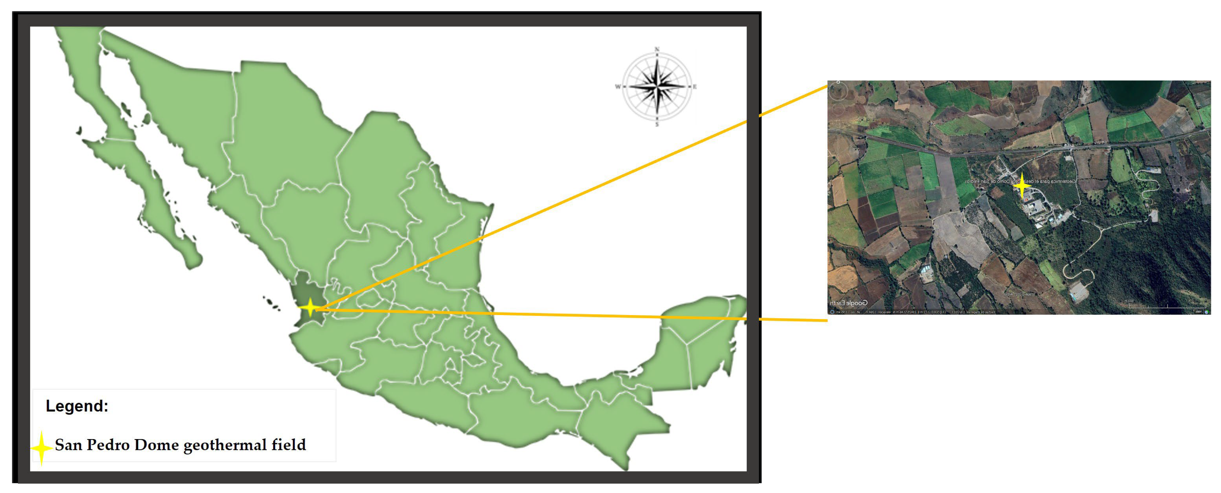
Worldwide, Mexico ranks seventh in geothermal energy production, with five geothermal fields in operation [40]. The most recent geothermal field (Domo de San Pedro) is located in the municipality of San Pedro Lagunillas, in the state of Nayarit, Mexico (Figure 1). In this field, the geothermal fluid, mainly steam, is extracted through natural artesian flow due to the high reservoir pressure, which eliminates the need for mechanical pumping and thereby minimizes auxiliary power consumption. This steam or steam–water mixture is conducted to the surface through production pipelines, where it is used to generate power or as useful heat for various purposes [41].

Figure 1.
Location map of the San Pedro Dome geothermal field.
Geologically, it is a volcanic structure composed of rhyolitic domes and comprises the western part of the Transmexican Volcanic Belt [42]. It is characterized by intense hydrothermal activity that has been the subject of geological, geophysical, and geochemical studies, given its geothermal potential [42,43,44].
The wells drilled in the Domo de San Pedro geothermal field have been recorded as ranging from 145 °C to 180 °C in shallow zones up to 1000 m and between 230 °C and 320 °C at deeper levels [44]. With these temperatures being mainly reported in shallow zones, it is possible to obtain the thermal requirements to operate the proposed system.
2.2. Description of the Proposed System
As shown in Figure 2, the proposed cycle combines three thermodynamic cycles: an absorption cooling system (ACS), a heat transformer (HT), and an organic Rankine cycle (ORC). The ACS and the HT operate with a water/lithium bromide mixture, while the ORC uses the refrigerant R123. Regarding the choice of the working fluid in the ORC, the main aspects considered were as follows:
- The selection of the working fluid for the ORC was restricted to fluids classified as isentropic. This ensures that, during expansion in the turbine, the organic fluid at state 21 (see Figure 2) remains in a superheated vapor state, regardless of the expansion ratio. This avoids imposing a constraint on the expansion pressure, which would be necessary when using a wet fluid. Conversely, for dry fluids, a larger expansion results in greater superheating at the turbine exit, which reduces the useful enthalpy available for power generation;
- Critical temperature: only fluids with a critical temperature above the reference heat supply temperature (150 °C) were considered;
- Environmental impact: the selection prioritized fluids with a low environmental impact, specifically those with a low global warming potential (GWP) and ozone depletion potential (ODP);
- Safety: the working fluid, particularly at the highest temperatures in the cycle, had to pose no risk of explosion or flammability;
- Thermal efficiency: the fluid was also required to offer an attractive thermal efficiency.
These criteria significantly limited the number of suitable working fluids for the ORC. In fact, none of the hydrocarbons with potential for ORC applications that were proposed by Bahrami et al. [45] met all the specified requirements. Regarding the thermodynamic evaluation of 57 working fluids conducted by Zhang et al. [46], it was found that R113, R123, and R141b are the isentropic fluids with the highest thermal efficiency. However, R113 is not an eco-friendly refrigerant [47] and R141b has a GWP of 745 and an ODP of 0.12 [48]. Therefore, R123 was selected as the working fluid, as it meets the environmental and safety requirements and was also identified by Zhang et al. [46] as a suitable choice, particularly for the utilization of a closed-type heat source.
Regarding the integrated absorption cycle, it is widely acknowledged that, historically, the most commonly used working pairs in absorption systems have been the H2O–LiBr and NH3–H2O mixtures, each of which has distinct characteristics that make them suitable for various applications. For instance, using ammonia as the refrigerant allows for evaporation temperatures well below 0 °C, which makes the NH3–H2O mixture particularly advantageous for low-temperature applications such as product preservation. On the other hand, when using the H2O–LiBr mixture, the operating pressures are typically below atmospheric pressure, which enables the design of less robust and, therefore, more cost-effective systems. However, for the same evaporation temperature, it was found that the working pair utilizing H2O–LiBr has better system performance than that that which utilizes NH3–H2O [49]. Further, Verma et al. [49] found that, for a H2O–LiBr double-effect cycle in parallel configuration (similar to that proposed in the present study), the COP is superior at heat supply temperatures higher than 150 °C. For these reasons, the H2O/LiBr mixture was chosen for the absorption cycle.
As shown in Figure 2, the proposed cycle is designed to integrate three thermodynamic cycles: an absorption cooling system (ACS), a heat transformer (HT), and an organic Rankine cycle (ORC), in which the ACS and the HT share the generator and the condenser. In the ACS, a solution with a low concentration of LiBr leaves absorber 1 (state 1) and is pumped (state 2) to economizer 1, where it is preheated by the solution coming from the generator. The solution leaving economizer 1 (state 3) enters the generator, where an amount of heat () is supplied to the generator to separate part of the water contained in the solution. Then, the solution with a high LiBr concentration and at a high temperature, after leaving the generator, is divided into two streams. One goes to the economizer (state 4), preheating the solution coming from the absorber, while the other goes to the pumps of the HT cycle. The solution, leaving the economizer at a lower temperature (state 5), passes through a valve, which reduces its pressure before it enters the absorber (state 6). Meanwhile, the water in a vapor phase leaving the generator (state 7) enters the condenser and is then divided into two streams: one goes to the expansion valve (state 8) of the ACS, and the other goes to the pump of the HT. The water stream from the ACS passes through the expansion valve, which reduces its pressure and temperature (state 9) before it enters the evaporator. In the evaporator at a low temperature, the cooling effect is produced by removing an amount of heat () from the surroundings. The water in a vapor phase, leaving the evaporator at a low temperature (state 10), enters the absorber, where it is absorbed by the solution coming from the generator, which completes the absorption cooling cycle. Regarding the performance of the HT, the solution leaving the generator (state 11) is pumped to economizer 2 (state 12), where it is preheated by the solution coming from absorber 2. The solution leaving economizer 2 (state 13) enters absorber 2 after absorbing the water coming from the evaporator HT. The solution with low salt concentration, leaving absorber 2 at a high temperature (state 14), enters economizer 2, preheating the solution coming from the generator. The solution leaving economizer 2 (state 15) passes through a valve, which reduces its pressure (state 16) before it enters the generator. On the other hand, the solution leaving the condenser (state 17) is pumped (state 18) to the evaporator HT, where a certain amount of heat () is supplied to the component to evaporate the water. The water in a vapor phase, leaving this component, enters absorber 2, where it is absorbed by the solution coming from the generator, delivering an amount of heat at the highest system temperature. The heat produced by the exothermic reaction into the absorber 2 is used to drive the ORC. In the ORC, the refrigerant R123 is first evaporated by the heat supplied by absorber 2 (state 20). Then, the refrigerant, at high pressure and temperature, passes through the turbine, producing power (). Part of the refrigerant expanded in the turbine exits at an intermediate pressure and temperature (state 23), while the rest is completely expanded in the turbine (state 21). This refrigerant is condensed (state 22) in condenser 1 of the ORC and then pumped (state 25) to the evaporator of the ORC. Meanwhile, the other stream leaving the turbine is condensed at a relatively high temperature in condenser 2 of the ORC, and this heat is used for the desalination processes. The condensed water (state 24) joins the other stream (state 26) and is then pumped (state 26), which closes the organic Rankine cycle.

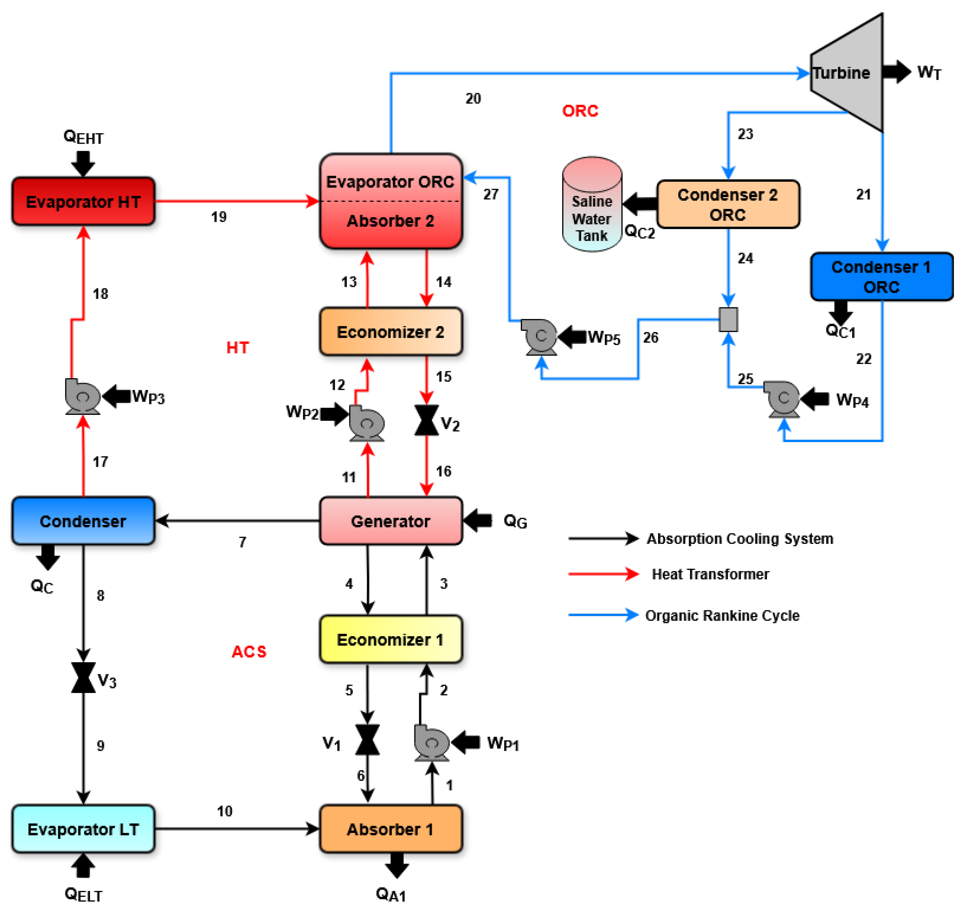
Figure 2.
Proposed system for simultaneous generation of cooling, power, and water desalination.
Figure 2.
Proposed system for simultaneous generation of cooling, power, and water desalination.
3. Mathematical Model
To evaluate the system’s performance, mass and energy balances were developed for each of its components. These balances determine the heat and power flows involved in each component. Table 1 shows the equations for modeling each component.

Table 1.
Mass and energy balances for each component of the proposed system.
The net power () of the system is determined by subtracting the power consumed by the pumps () from the power generated by the turbine (). Equation (1) is used to calculate this parameter.
To carry out the water desalination process, the heat dissipated by condenser 2 of the organic Rankine cycle is used. Based on the available thermal energy (), the evaporated water flow rate can be determined using Equation (2).
where is the specific heat of the fluid, ∆T represents the temperature difference between the fluid entering the system and the temperature at which boiling occurs, and represents the thermal energy associated with the phase change.
The thermal energy supplied to the system by the geothermal source () is determined using Equation (3), which represents the sum of the heat required by the generator () and the high-temperature evaporator ().
Equation (4) is used to determine the EUF, which is considered analogous to thermal efficiency, as it relates the energy outputs obtained from the system to those supplied to it. In this case, the EUF depends on the net power (), the cooling load (), and the thermal energy available for desalination (), as well as the heat supplied by the geothermal source ().
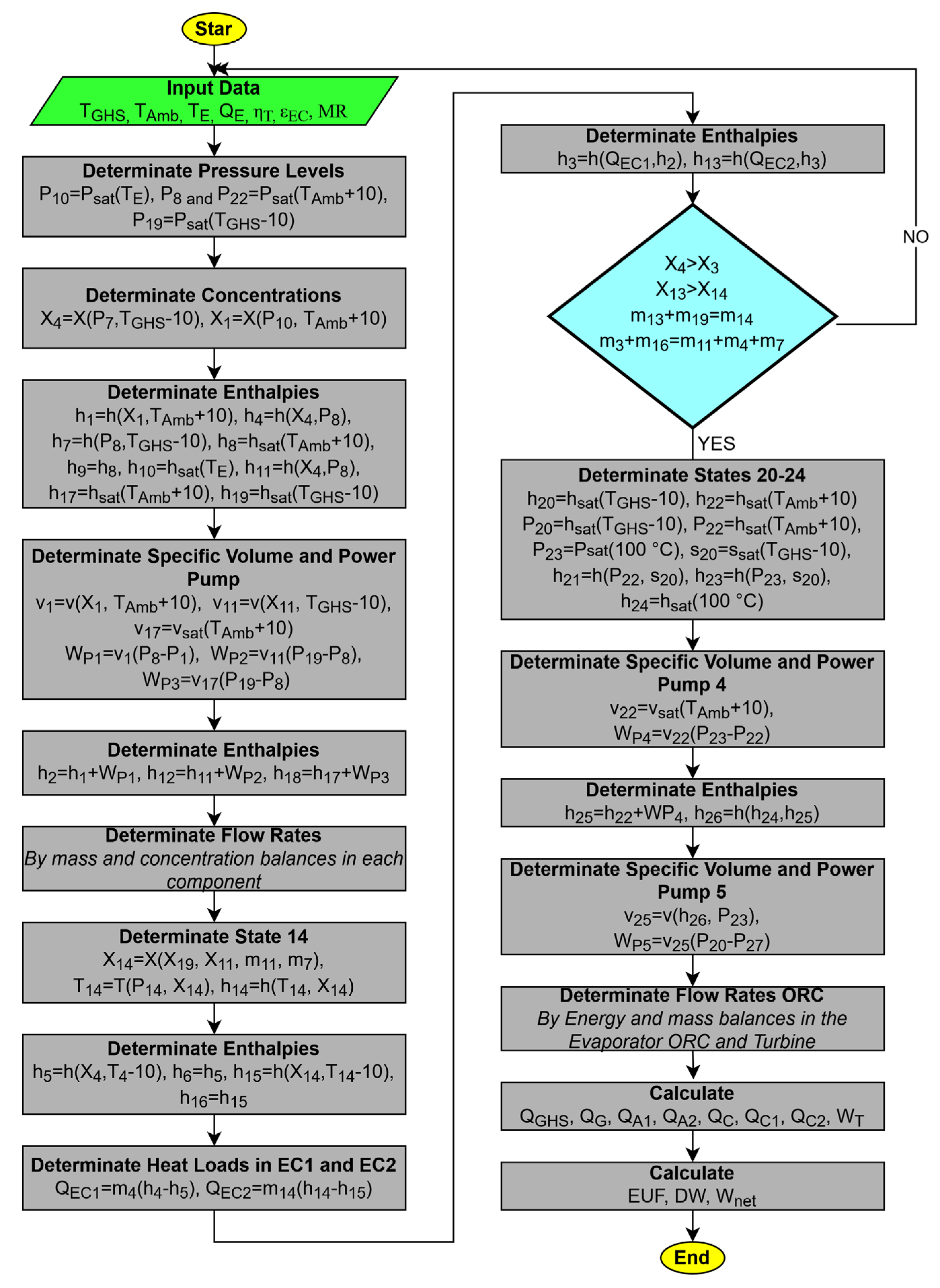
System Solution Flowchart
For system evaluation, an algorithm was developed using the Engineering Equation Solver (EES) software. This algorithm enables the determination of the thermodynamic properties of the lithium bromide–water mixture and the analysis of the proposed system’s performance under various operating conditions.
It is important to mention that the following assumptions were considered when solving the proposed system using the developed algorithm:
- The system operates under steady-state conditions;
- Heat and pressure losses between component connections are neglected;
- The fluid is considered a saturated vapor at states 10, 19, and 20;
- The fluid is considered a saturated liquid at states 1, 8, 17, 22, and 24;
- The processes in the valves are considered isenthalpic;
- The temperature difference between the condensation process and the environment is 10 °C;
- The temperature difference between the geothermal source and the EHT, as well as between the geothermal source and the generator, is 10 °C.
Figure 3 shows the algorithm solution process, where the input variables are entered into the software. In this case, a cooling heat load () of 100 kW was established, as well as the source temperature (TGHS), ambient temperature (TAmb), economizer effectiveness (ε), and turbine efficiency (ηT). Once these values are entered, the pressure levels under which the system operates are determined, using the saturation states as a reference. With the pressure and temperature levels at states 4 and 1, the concentration of the mixture in the cooling system streams is determined. Knowing the pressure, temperature, and concentration levels, and considering the saturation states at the condenser, absorber, and generator outlets, the enthalpies at states 1, 4, 7, 8, 9, 10, 11, 17, and 19 are determined. Subsequently, based on the pressure levels and fluid conditions at the pump inlet, the power pump and the enthalpy of the fluids at the outlet of these components can be determined (states 2, 12, and 18). Using mass balances for each component, the fluid flows within the system are determined, and with these, states 14, 5, 6, 15, and 16 can be determined. With the effectiveness of the thermal energy transfer in the economizers, the enthalpies of states 3 and 13 are determined. At this point, the computational model compares the concentration values in both the heat transformer (HT) and the absorption cooling system (ACS). If the concentrations are adequate, the states corresponding to the organic cycle are determined and, finally, the evaluation parameters, DW, , and EUF, are calculated. If the flow rates or concentrations are inadequate, the process is repeated, and the input variables must be adjusted.
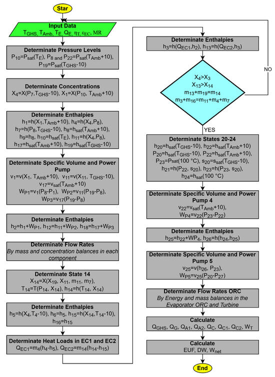
Figure 3.
Flowchart of the solution of the proposed model.
4. Comparison of the Proposed Model
The proposed system features a novel configuration that combines a vapor absorption refrigeration cycle, a heat transformer, and an organic Rankine cycle for the simultaneous generation of power, cooling, and water desalination.
To date, no system with a similar configuration and the same benefits has been reported in the literature. Consequently, direct validation of the proposed system is not possible.
However, to evaluate the results that were obtained, two reference models with similar operating principles were selected. These models use absorption systems to achieve both cooling and water desalination.
Table 2 presents the results obtained from the present model and the system proposed by Delgado et al. [50], who developed a system to simultaneously achieve the cooling effect and the desalination of water through boiling. They utilize an absorption refrigeration system and a heat transformer, which employs a lithium bromide–water mixture as the working fluid.
Table 2.
Comparison of the system proposed by Delgado et al. [50] and the present work.
A second comparison was carried out; however, the reference model has a low cooling capacity. Table 3 presents the comparison conditions, as well as the output values that were obtained: the cooling capacity, amount of desalinated water, and turbine power.
Table 3.
Comparison of the system proposed by Gude et al. [51] and the present work.
The systems used for comparison can only carry out the cooling effect and water desalination processes simultaneously. This represents an advantage for the proposed system, as not only can it generate these outputs but it can also produce a certain amount of mechanical power. In the first comparison case, under similar operating conditions, the model proposed in this work produces 15.64% more desalinated water and generates a turbine power output of 5.65 kW.
5. Analysis of Results
One of the main variables that influences the system’s performance is the temperature of the geothermal source (TGHS), as both the generation temperature (TG) and the temperature of the working fluid at the outlet of the high-temperature evaporator (EHT) depend on it. Another relevant variable is the ambient temperature (TAmb), as all the system’s condensation processes, as well as the absorption process in the low-pressure line, depend on this variable. Finally, the flow rate split at the condenser (MR) is also significant, as part of the flow is directed to the heat transformer while the remaining portion circulates through the cooling system. In the MR analysis, an increase in its value indicates that most of the flow circulates through the low-temperature evaporator. This variable plays an important role, as it limits the thermal energy that is available for the energy generation process. Figure 4, Figure 5, Figure 6, Figure 7, Figure 8, Figure 9, Figure 10, Figure 11, Figure 12 and Figure 13 show the behavior of the main parameters that determine the performance of the proposed system as a function of the aforementioned variables. In each analysis, five operating cases were evaluated, each corresponding to a different refrigerant temperature (TE) in the ACS. This temperature reflects the conditions under which the cooling effect is most effective and suggests situations in which it might be useful.
5.1. System Analysis Based on Geothermal Source Temperature (TGHS)
Figure 4 shows the behavior of the net power produced by the system () as a function of increases in the geothermal source temperature (TGHS). In the proposed system, both the temperature generator (TG) and the high-temperature evaporator (TEHT) depend on the TGHS. At higher source temperatures, there is greater availability of thermal energy for heating the organic fluid. If the organic fluid reaches a higher temperature, a greater amount of power can be produced during the expansion process in the turbine; therefore, the net power increases with a rising TGHS.
Furthermore, within a TGHS range of 100–120 °C, a greater power output is achieved when the system is operating at high evaporation temperatures. For instance, at a geothermal source temperature of 105 °C, a net power of 8 kW can be obtained when the system evaporates at 10 °C, while for that same temperature level but evaporating at 2 °C, the net power produced is 6.4 kW.
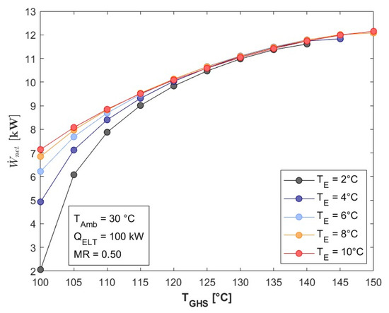

Figure 4.
as a function of .
Figure 4.
as a function of .
As the geothermal source temperature rises, both the net power output and desalinated water (DW) production increase. Figure 5 shows the behavior of the DW as a function of TGHS.
With higher evaporation temperatures in the low-pressure line, the refrigerant requirement increases to produce the desired cooling load. Therefore, all flow rates within the system increase as the evaporation temperature increases. With a greater flow of organic fluid through condenser 2 of the ORC, the availability of thermal energy for the desalination process also increases. Therefore, the desalination process improves as the geothermal source temperature increases. The water desalination rates range between 50 and 52 L/h with a thermal source temperature of 140 °C and refrigerant evaporation in the low-pressure line between 2 and 10 °C.
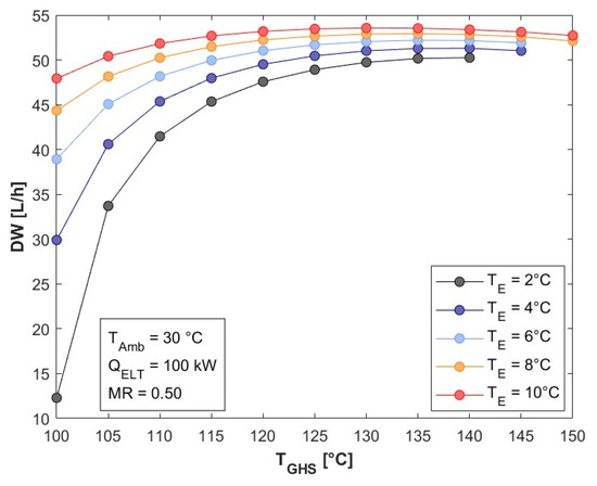
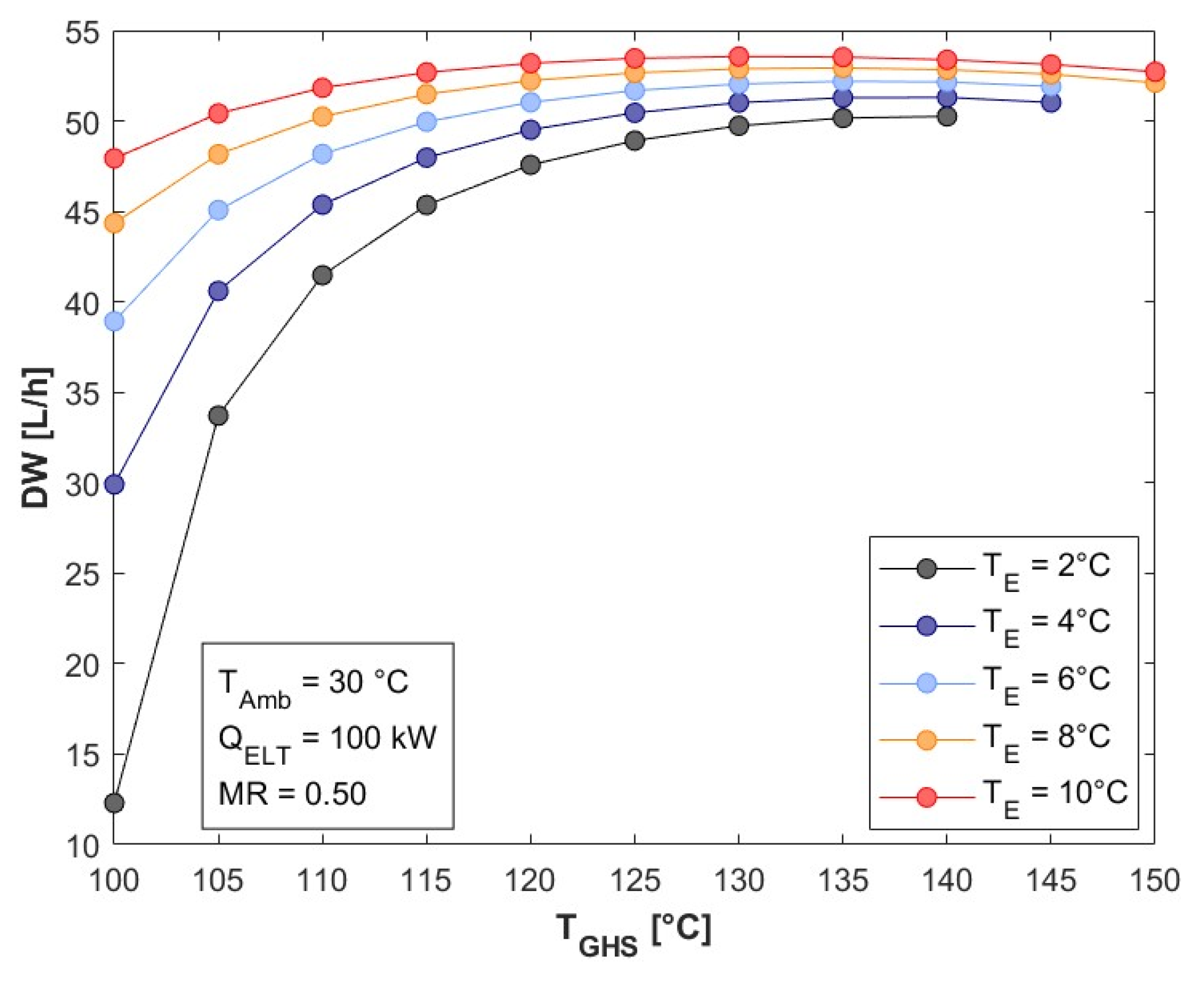
Figure 5.
DW as a function of TGHS.
Figure 5.
DW as a function of TGHS.
Figure 6 shows the behavior of the EUF as a function of the geothermal source temperature. As the source temperature increases from 100 to 140 °C, which evaporation at 2 °C, the EUF improves by 28.13%, rising from 0.32 to 0.41.
As can be seen in Equation (4), the EUF depends on the energy produced by the system and the thermal energy supplied to it. As previously mentioned, as the TGHS increases, the system flow rates also grow, raising the thermal energy supplied by the geothermal source to both the generator and the high-temperature evaporator. Specifically, there is a 3.9% increase in the thermal energy supplied to the system as the TGHS rises from 100 to 140 °C. However, for this same increase in the TGHS, the net power and thermal energy available for water desalination are improved by 463% and 308%, respectively. Therefore, the EUF consistently improves as the TGHS increases.
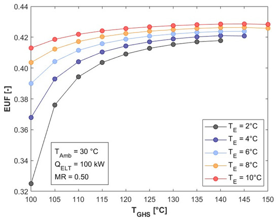
Figure 6.
EUF as a function of TGHS.
Figure 6.
EUF as a function of TGHS.
5.2. System Analysis Based on Ambient Temperature (TAmb)
As a result of the increase in ambient temperature, the net power generated by the system tends to decrease, as shown in Figure 7. High ambient temperatures affect the system’s condensation processes, causing them to occur at higher temperatures. Consequently, the refrigerant entering the evaporator has a higher temperature. This increases the refrigerant demand in the low-temperature evaporator and, therefore, also increases the remaining flows in both the cooling system and the heat transformer. As the flow rates reaching absorber 2 increase, the energy available for transfer to the organic cycle decreases, which thus reducing the flow of organic fluid through the ORC. This lower energy availability is primarily due to the reduced preheating of the fluid coming from economizer 2 to absorber 2 due to the increased mass flow rate.
On the other hand, Figure 7 also shows that, when operating at evaporation temperatures of 8 and 10 °C, when TAmb is higher than 30 °C, the power reduction is less significant than when evaporating at 2, 4, and 6 °C. At high evaporation temperatures, the decrease in thermal energy availability is offset by the increase in flow in the heat transformer absorber, which helps prevent a rapid decrease in the amount of organic fluid entering the turbine. For evaporation temperatures of 2 and 10 °C, a decrease in the organic fluid flow of 12.5% and 3.85%, respectively, will be obtained when the ambient temperature increases from 25 to 35 °C. In these cases, the turbine power decreases from 12.42 kW to 10.32 kW for evaporation at 2 °C and from 11.87 kW to 11.35 kW for evaporation at 10 °C.
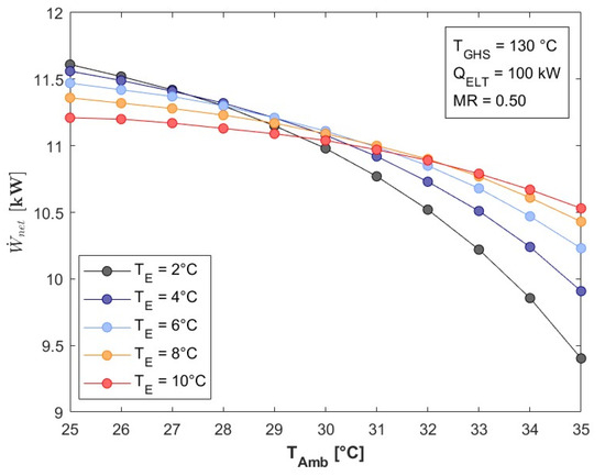
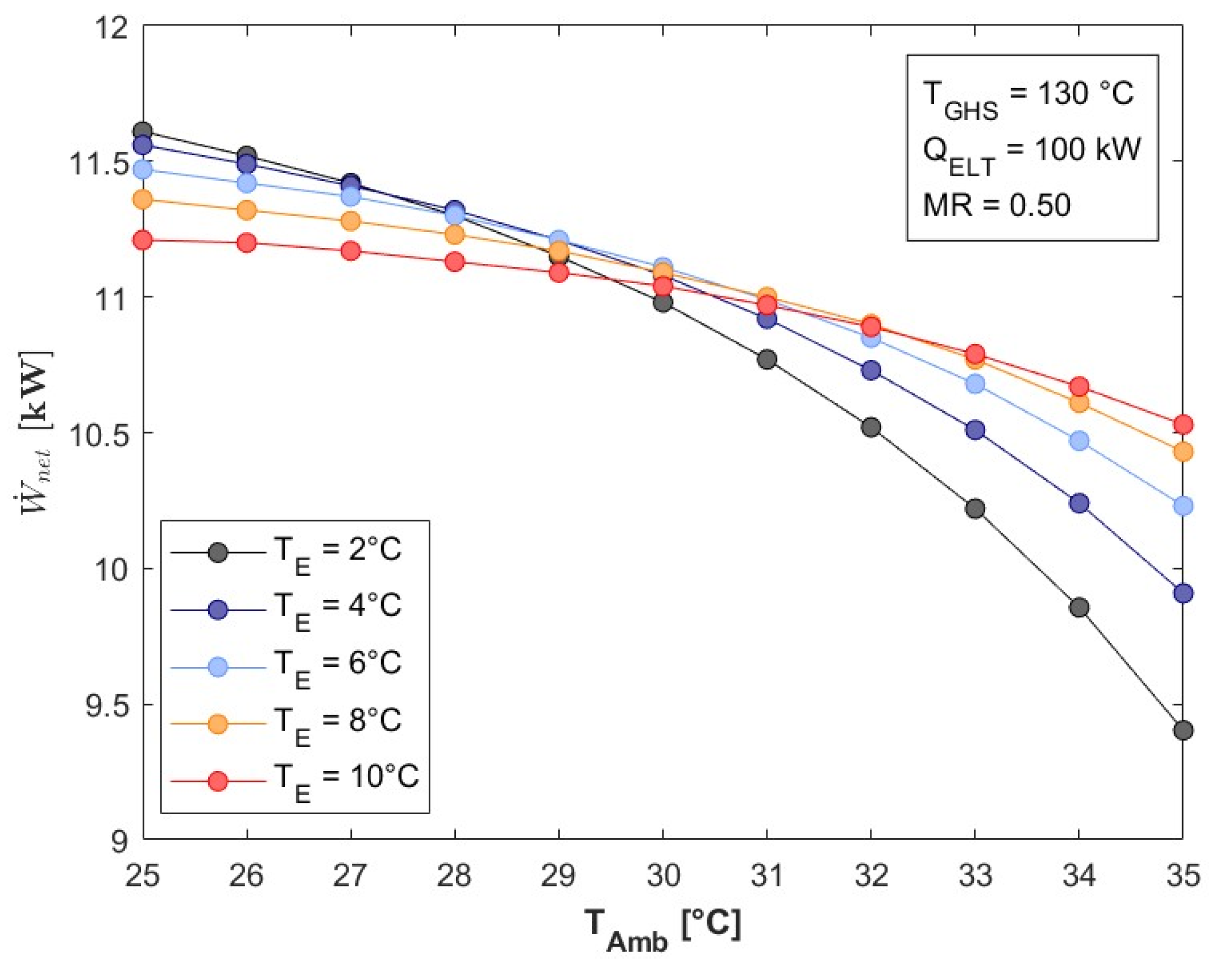
Figure 7.
as a function of TAmb.
Figure 7.
as a function of TAmb.
The decrease in organic fluid circulating through the ORC, resulting from the lower energy availability caused by the increase in ambient temperature, causes the desalination of water by the system to decrease. Figure 8 shows the production of desalinated water as a function of the ambient temperature. The lowest amount of water obtained is 43.09 L/h, when evaporating at 2 °C with an ambient temperature of 35 °C, while the highest volume of water obtained corresponds to the conditions of TE = 10 °C and TAmb = 25 °C, which is equivalent to a volume of 54.13 L/h.
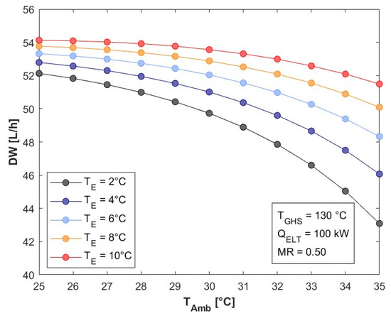
Figure 8.
DW as a function of TAmb.
Figure 8.
DW as a function of TAmb.
Due to the decrease in net power (see Figure 7) and water desalination (see Figure 8), the EUF decreases as the ambient temperature increases. Figure 9 shows that the system’s EUF ranges from 0.30 to 0.43 for any evaporation case. Furthermore, when evaporating at 2 °C, increasing the ambient temperature by 10 °C causes the EUF to decrease from 0.42 to 0.39, which represents a decrease of 7.14%.
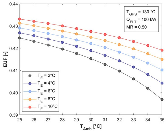
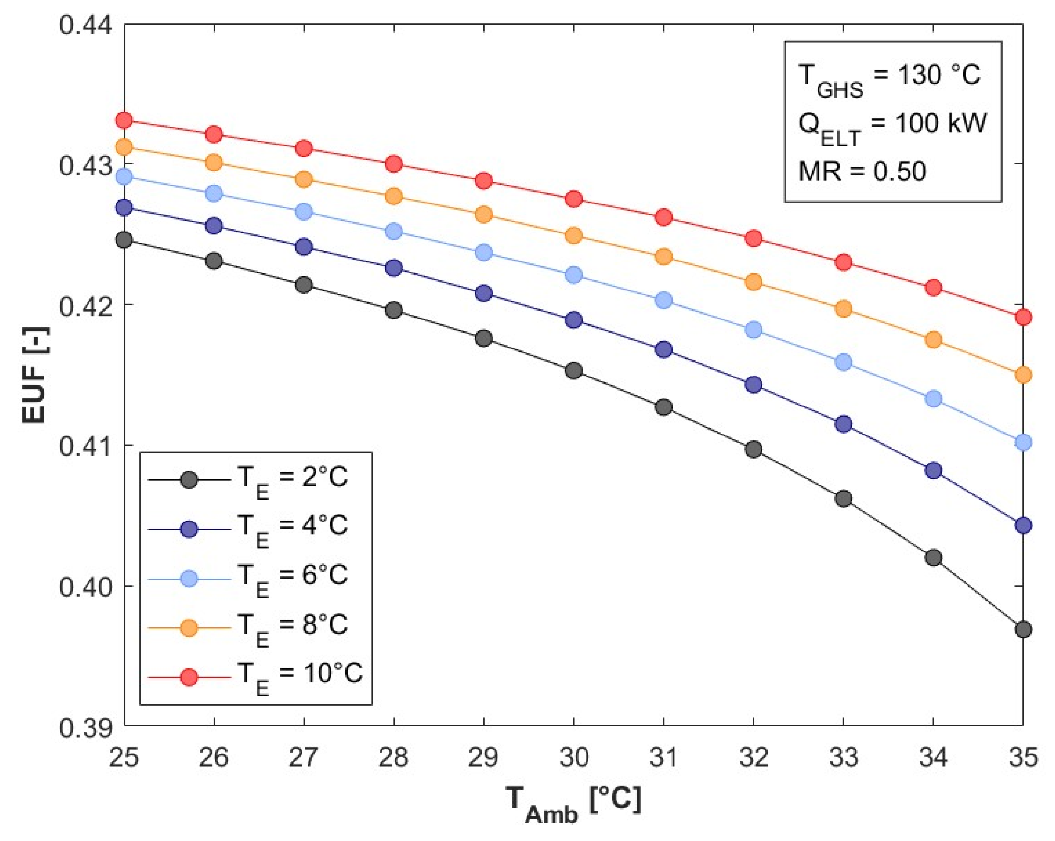
Figure 9.
EUF as a function of TAmb.
Figure 9.
EUF as a function of TAmb.
5.3. System Analysis Based on Mass Ratio (MR)
In the system configuration, the refrigerant fluid is divided at the condenser outlet, where a part is used to generate the cooling effect, while the remaining fraction is used in the heat transformer to supply the thermal energy required by the organic cycle.
Figure 10 shows the behavior of the main system flows as a function of the mass distribution ratio in the condenser. With a set cooling capacity, the refrigerant flow circulating through the low-temperature evaporator remains constant (). It can also be observed that the flow through the heat transformer () diminishes as a greater percentage is allocated to the cooling component. This effect results in a smaller amount of thermal energy being transferred to the organic cycle and, as a result, reduces the organic fluid flow entering the turbine ().
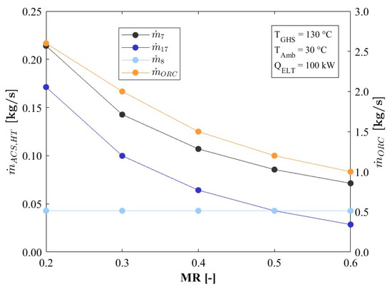

Figure 10.
Flow rates as a function of MR.
Figure 10.
Flow rates as a function of MR.
Figure 11 shows how the net power output of the system decreases when the majority of the refrigerant is used for cooling. When the mass flow ratio increases from 0.20 to 0.60, the turbine’s power decreases by more than 80%, from 33.45 kW to 6.47 kW, at an evaporation temperature of 0 °C.
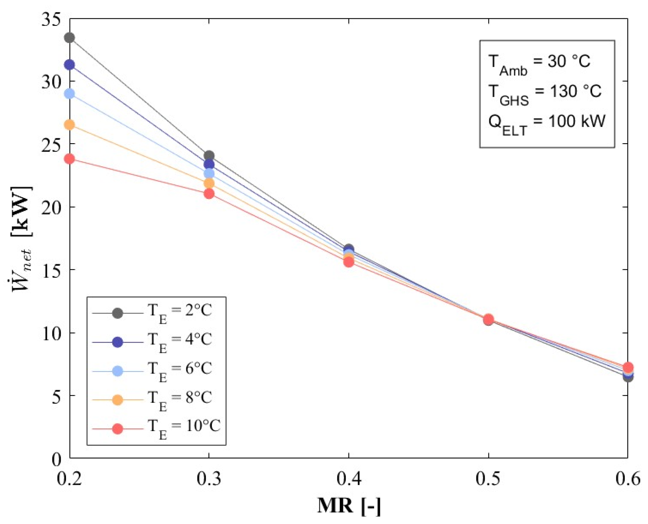
Figure 11.
as a function of MR.
Figure 11.
as a function of MR.
As the mass flow rate of the refrigerant through the heat transformer decreases, so does the flow rate of the organic fluid through the turbine (see Figure 8). Therefore, the energy available for the desalination process is reduced. Figure 12 shows the decrease in the volume of desalinated water as a function of the flow rate in the condenser. It can be seen that values greater than 200 L/h can be obtained when the mass ratio is set to 0.20, which means that 20% of the refrigerant is used for cooling and the remaining 80% for the heat transformer.
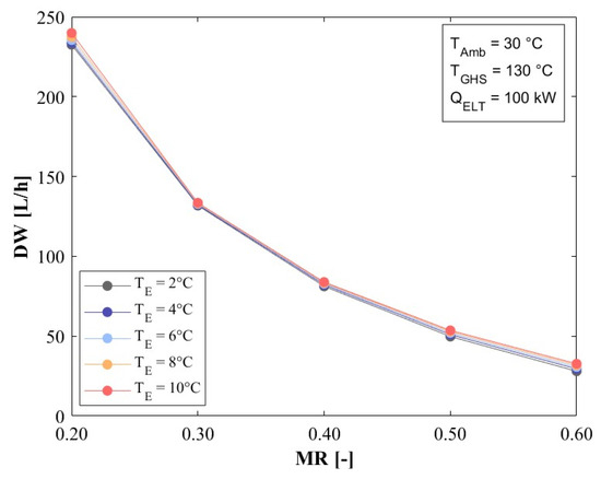
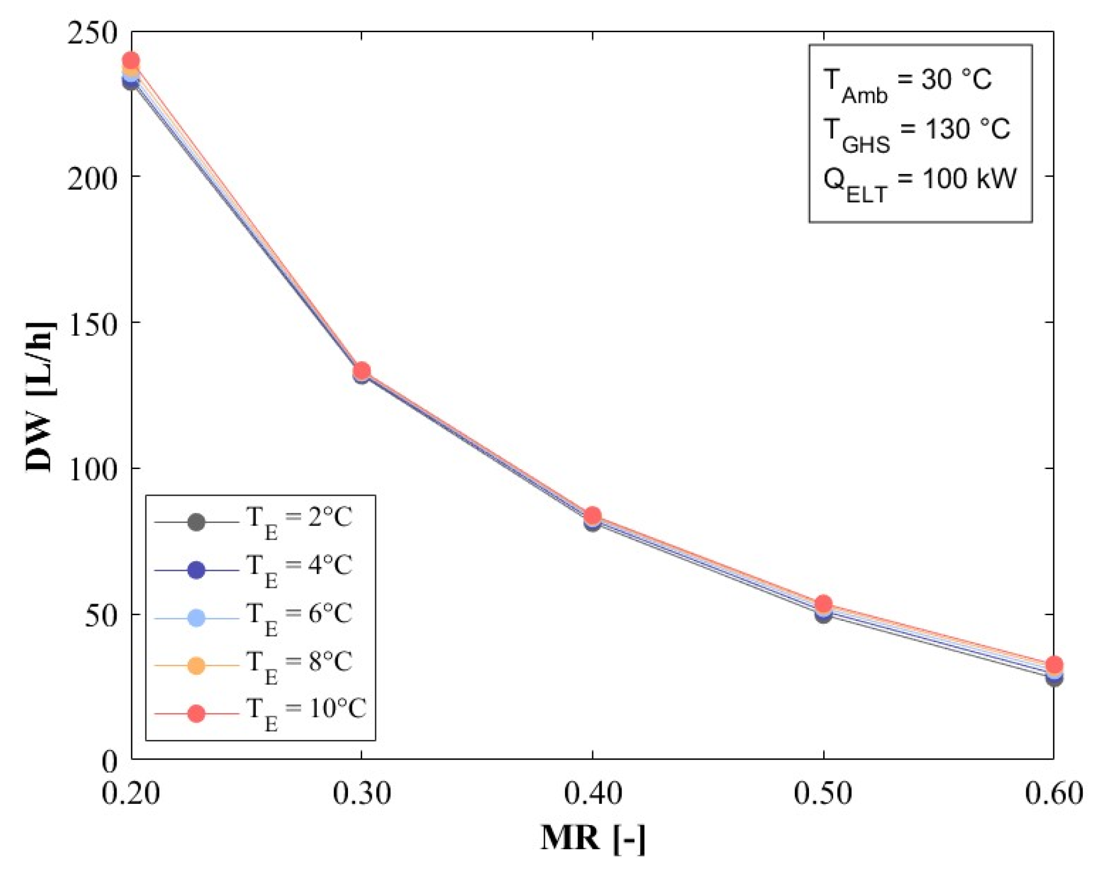
Figure 12.
DW as a function of MR.
Figure 12.
DW as a function of MR.
As the net power output declines and the heat available for the desalination process decreases, the EUF might be expected to follow a similar trend. However, Figure 13 shows that this parameter benefits from increasing the mass ratio (MR). The EUF improves from 0.29 to 0.45 as the MR increases from 0.20 to 0.60 when the refrigerant evaporates at 0 °C. Although there is an 80.6% decrease in net power and an 87.9% decrease in the energy available to desalinate the water, the cooling capacity remains constant, and the heat supplied by the source for system operation decreases considerably (72.6%). Therefore, the EUF improves.
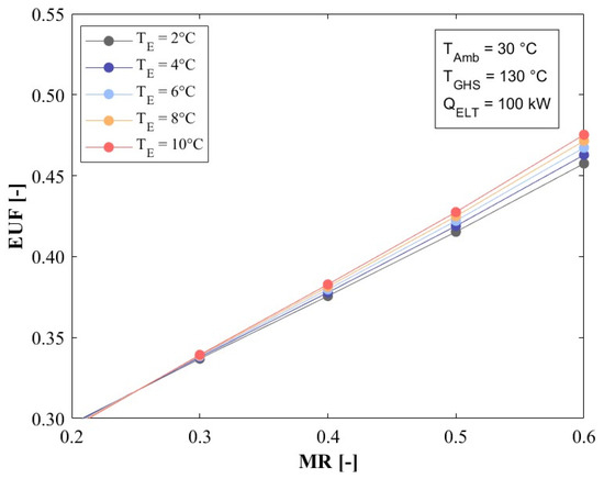
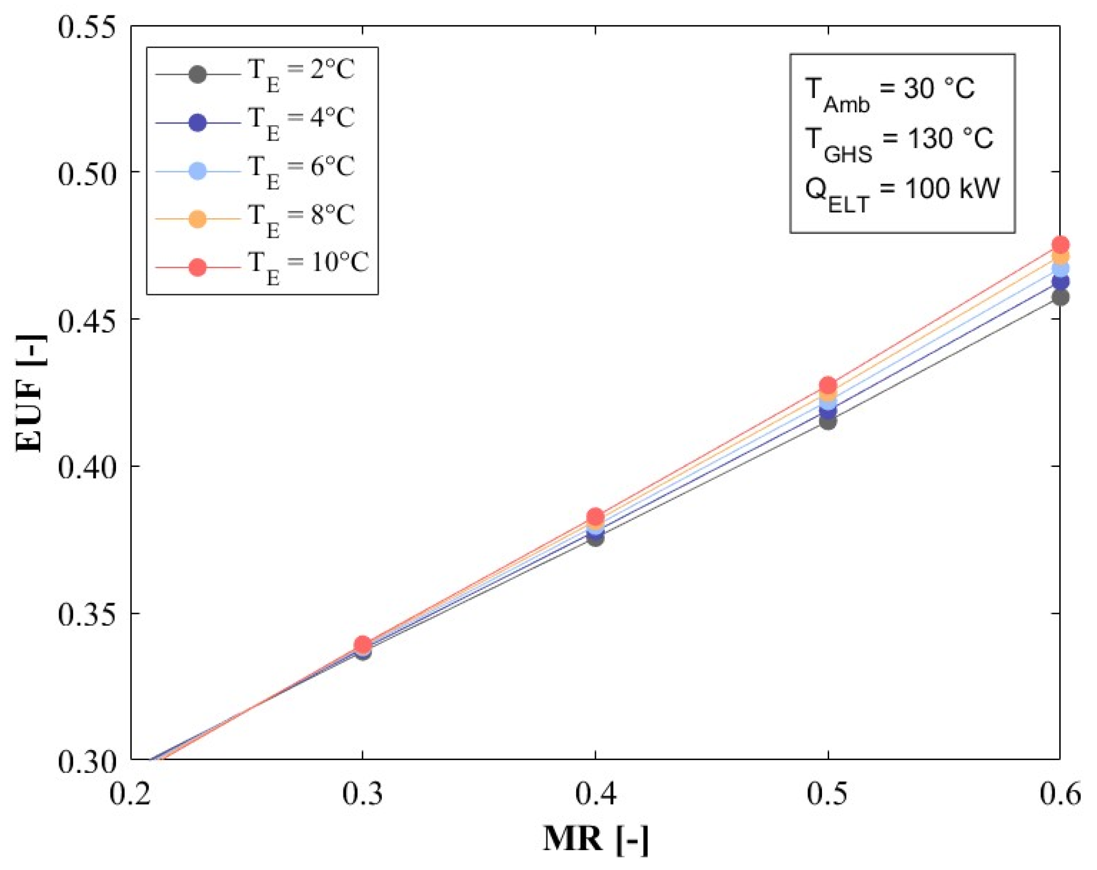
Figure 13.
EUF as a function of MR.
Figure 13.
EUF as a function of MR.
6. Conclusions
The performance of the polygeneration system for the simultaneous production of power, cooling, and freshwater described herein was theoretically evaluated at heat source temperatures between 100 and 150 °C, which a geothermal well could provide. The results showed that the system performance considerably depends on the analyzed parameters. The polygeneration system exhibits a significant enhancements in its power output, freshwater production, and energy utilization factor as the heat source temperature increases. At a heat source temperature of 150 °C and a mass ratio of 0.5, the system achieves up to 13 kW of power, 50 L/h of freshwater, and an energy utilization factor of 0.42. Additionally, it provides a cooling load of 100 kW. However, these parameters decrease considerably with an increase in the ambient temperature, which indicates that this parameter is also highly relevant to system performance, as the same parameters reach values of just 9.3 kW, 43 L per hour, and 0.395, respectively, at the highest ambient temperatures of 35 °C. The results showed that another relevant parameter was the mass ratio, since the power and freshwater production considerably decreased with an increase in this parameter. That is, as higher amounts of water flow through the absorption cooling cycle, the power production and freshwater decrease since lower water mass flow rates are circulating in the high-temperature cycles. From the results, it was theoretically shown that the polygeneration system is capable of producing the three outputs when geothermal energy is supplied.
Author Contributions
Conceptualization, W.R., A.P.-R., J.C.J.-G., J.S.-V. and G.L.G.-U.; methodology, W.R., J.C.J.-G. and A.P.-R.; software, A.P.-R. and J.C.J.-G.; comparison, A.P.-R.; formal analysis, A.P.-R. and W.R.; investigation, J.C.J.-G., G.L.G.-U. and J.S.-V.; data curation, A.P.-R.; writing—original draft preparation, W.R., A.P.-R., J.C.J.-G., J.S.-V. and G.L.G.-U.; writing—review and editing, W.R., A.P.-R., J.C.J.-G., J.S.-V. and G.L.G.-U.; visualization, A.P.-R. and J.S.-V.; supervision, W.R.; project administration, W.R. All authors have read and agreed to the published version of the manuscript.
Funding
This research received no external funding.
Data Availability Statement
The dataset is available upon request from the authors.
Acknowledgments
Alejandro Pacheco acknowledges the financial support provided by CONAHCYT through the postdoctoral program. Juliana Saucedo acknowledges CONAHCYT for the support given through the “Investigadores por México” program. Wilfrido Rivera acknowledges the financial support provided by CONAHCYT through the sabbatical program “Estancias Sabáticas Vinculadas a la Consolidación de Grupos de Investigación”.
Conflicts of Interest
The authors declare no conflicts of interest.
Nomenclature
The following abbreviations are used in this manuscript:
| Abbreviations | |||
| ACS | Absorption Cooling System | PgS | Polygeneration Systems |
| AHT | Absorption Heat Transformer | RO | Reverse Osmosis |
| CGMD | Conductive Gap Membrane Distillation | Letters and Subscripts | |
| DW | Desalinated Water | A | Absorber |
| Ec | Econimizer | C | Condenser |
| ELT | Evaporator Low Temperature | E | Evaporator |
| EHT | Evaporator High Temperature | G | Generator |
| EUF | Energy Utilization Factor | GHS | Geothermal Heat Source |
| GT | Gas Turbine | P | Pump |
| H-Dh | Humidification-Dehumidification | T | Turbine |
| HT | Heat Transformer | V | Valve |
| MED | Multi-Effect Desalination | Symbol | |
| MED/TVC | Multiple Effect Desalination/Thermal Vapor Compression | Heat [kW] | |
| MR | Mass Ratio | Power [kW] | |
| ORC | Organic Rankine Cycle | Mass flow [kg/s] | |
| PEME | Proton Exchange Membrane Electrolysis | ΔT | Temperature difference |
| PGMD | Permeate Gap Membrane Distillation | ||
References
- Mekonnen, M.M.; Hoekstra, A.Y. Four Billion People Facing Severe Water Scarcity. Sci. Adv. 2016, 2, e1500323. [Google Scholar] [CrossRef] [PubMed]
- Gokcen, G.; Kemal Ozturk, H.; Hepbasli, A. Overview of Kizildere Geothermal Power Plant in Turkey. Energy Convers. Manag. 2004, 45, 83–98. [Google Scholar] [CrossRef]
- Aksoy, N. Power Generation from Geothermal Resources in Turkey. Renew. Energy 2014, 68, 595–601. [Google Scholar] [CrossRef]
- Daǧdaş, A.; Öztürk, R.; Bekdemir, Ş. Thermodynamic Evaluation of Denizli Kızıldere Geothermal Power Plant and Its Performance Improvement. Energy Convers. Manag. 2005, 46, 245–256. [Google Scholar] [CrossRef]
- Lewis, W.; Wallace, K.; Dunford, T.; Harvey, W. Kizildere II Multiple-Flash Combined Cycle: A Novel Approach for a Turkish Resource. In Proceedings of the World Geothermal Congress, Hailey, ID, USA, 19 April 2015. [Google Scholar]
- Anvari, S.; Mahian, O.; Taghavifar, H.; Wongwises, S.; Desideri, U. 4E Analysis of a Modified Multigeneration System Designed for Power, Heating/Cooling, and Water Desalination. Appl. Energy 2020, 270, 115107. [Google Scholar] [CrossRef]
- Hamrang, F.; Shokri, A.; Mahmoudi, S.M.S.; Ehghaghi, B.; Rosen, M.A. Performance Analysis of a New Electricity and Freshwater Production System Based on an Integrated Gasification Combined Cycle and Multi-Effect Desalination. Sustainability 2020, 12, 7996. [Google Scholar] [CrossRef]
- Lei, M.; Alves, J.C.; Alotaibi, M.A.; Chen, J. A Novel Polygeneration Process Integrated into a Gas Turbine Cycle toward an Environmentally Friendly Framework; Application of a Comprehensive 4E Study. Energy 2024, 307, 132728. [Google Scholar] [CrossRef]
- Javadpour, A.; Javaran, E.J.; Lari, K.; Askari, I.B. Techno-Economic Analysis of Combined Gas Turbine, MED and RO Desalination Systems to Produce Electricity and Drinkable Water. Desalination Water Treat. 2019, 159, 232–249. [Google Scholar] [CrossRef]
- Cao, Y.; Delpisheh, M.; Yousefiasl, S.; Athari, H.; El-Shorbagy, M.A.; Jarad, F.; Dahari, M.; Wae-hayee, M. Examination and Optimization of a Novel Auxiliary Trigeneration System for a Ship through Waste-to-Energy from Its Engine. Case Stud. Therm. Eng. 2022, 31, 101860. [Google Scholar] [CrossRef]
- Safder, U.; Rana, M.A.; Yoo, C. Feasibility Study and Performance Assessment of a New Tri-Generation Integrated System for Power, Cooling, and Freshwater Production. Desalination Water Treat. 2020, 183, 63–72. [Google Scholar] [CrossRef]
- Gholizadeh, T.; Vajdi, M.; Rostamzadeh, H. Exergoeconomic Optimization of a New Trigeneration System Driven by Biogas for Power, Cooling, and Freshwater Production. Energy Convers. Manag. 2020, 205, 112417. [Google Scholar] [CrossRef]
- Zhang, M.; Chen, H.; Zoghi, M.; Habibi, H. Comparison between Biogas and Pure Methane as the Fuel of a Polygeneration System Including a Regenerative Gas Turbine Cycle and Partial Cooling Supercritical CO2 Brayton Cycle: 4E Analysis and Tri-Objective Optimization. Energy 2022, 257, 124695. [Google Scholar] [CrossRef]
- Soares, A.P.d.M.R.; de Araújo, H.V.; Dangelo, J.V.H. Thermodynamic Analysis and Optimization of a Biogas-Powered Trigeneration System to Produce Power, Cooling and Freshwater. Fluid. Phase Equilib. 2023, 573, 113872. [Google Scholar] [CrossRef]
- Abou Houran, M.; Ahmad, S.F.; Nutakki, T.U.K.; Agrawal, M.K.; Ghfar, A.A.; Ooi, J.B.; Albani, A.; Xie, S. Numerical Simulation and 4E Analysis of a Steam Methane Reforming-Based Multi Heat Recovery Process, Producing Electricity, Methanol, Fresh Water, Heating, and Coolant. Process Saf. Environ. Prot. 2023, 180, 511–534. [Google Scholar] [CrossRef]
- Ayou, D.S.; Zaragoza, G.; Coronas, A. Small-Scale Renewable Polygeneration System for off-Grid Applications: Desalination, Power Generation and Space Cooling. Appl. Therm. Eng. 2021, 182, 116112. [Google Scholar] [CrossRef]
- Dai, Z.; Yin, X. Investigating the Performance of a Gas Turbine System Combined with Steam Methane Reforming as a Thermochemical Recuperator in a Power, Cooling, Freshwater, and Hydrogen Production Multigeneration System. Energy 2024, 311, 133346. [Google Scholar] [CrossRef]
- Azizi, N.; Esmaeilion, F.; Moosavian, S.F.; Yaghoubirad, M.; Ahmadi, A.; Aliehyaei, M.; Soltani, M. Critical Review of Multigeneration System Powered by Geothermal Energy Resource from the Energy, Exergy, and Economic Point of Views. Energy Sci. Eng. 2022, 10, 4859–4889. [Google Scholar] [CrossRef]
- Khoshgoftar Manesh, M.H.; Onishi, V.C. Energy, Exergy, and Thermo-Economic Analysis of Renewable Energy-Driven Polygeneration Systems for Sustainable Desalination. Processes 2021, 9, 210. [Google Scholar] [CrossRef]
- Kabeel, A.E.; Algazzar, A.M.; Essa, F.A.; Elsheikh, A.H.; Sathyamurthy, R.; Manokar, A.M.; Shanmugan, S.; Panchal, H.; Kumar, R.; Abdelgaied, M. Geothermal and Solar Energy in Water Desalination and Power Generation: Comprehensive Review. Energy Syst. 2024, 1–40. [Google Scholar] [CrossRef]
- Pastor-Martinez, E.; Rubio-Maya, C.; Ambriz-Díaz, V.M.; Belman-Flores, J.M.; Pacheco-Ibarra, J.J. Energetic and Exergetic Performance Comparison of Different Polygeneration Arrangements Utilizing Geothermal Energy in Cascade. Energy Convers. Manag. 2018, 168, 252–269. [Google Scholar] [CrossRef]
- Calise, F.; d’Accadia, M.D.; Macaluso, A.; Piacentino, A.; Vanoli, L. Exergetic and Exergoeconomic Analysis of a Novel Hybrid Solar–Geothermal Polygeneration System Producing Energy and Water. Energy Convers. Manag. 2016, 115, 200–220. [Google Scholar] [CrossRef]
- Calise, F.; Cipollina, A.; Dentice d’Accadia, M.; Piacentino, A. A Novel Renewable Polygeneration System for a Small Mediterranean Volcanic Island for the Combined Production of Energy and Water: Dynamic Simulation and Economic Assessment. Appl. Energy 2014, 135, 675–693. [Google Scholar] [CrossRef]
- Angrisani, G.; Diglio, G.; Sasso, M.; Calise, F.; Dentice d’Accadia, M. Design of a Novel Geothermal Heating and Cooling System: Energy and Economic Analysis. Energy Convers. Manag. 2016, 108, 144–159. [Google Scholar] [CrossRef]
- Calise, F.; Dentice d’Accadia, M.; Macaluso, A.; Vanoli, L.; Piacentino, A. A Novel Solar-Geothermal Trigeneration System Integrating Water Desalination: Design, Dynamic Simulation and Economic Assessment. Energy 2016, 115, 1533–1547. [Google Scholar] [CrossRef]
- Musharavati, F.; Khanmohammadi, S.; Pakseresht, A. Proposed a New Geothermal Based Poly-Generation Energy System Including Kalina Cycle, Reverse Osmosis Desalination, Elecrolyzer Amplified with Thermoelectric: 3E Analysis and Optimization. Appl. Therm. Eng. 2021, 187, 116596. [Google Scholar] [CrossRef]
- Ghiasirad, H.; Asgari, N.; Khoshbakhti Saray, R.; Mirmasoumi, S. Thermoeconomic Assessment of a Geothermal Based Combined Cooling, Heating, and Power System, Integrated with a Humidification-Dehumidification Desalination Unit and an Absorption Heat Transformer. Energy Convers. Manag. 2021, 235, 113969. [Google Scholar] [CrossRef]
- Shi, P.; Shang, R. Performance Evaluation and Optimization of a Multigeneration Hybrid System for Power, Hydrogen, Cooling, and Freshwater Production from Renewable Sources. Appl. Therm. Eng. 2024, 246, 122866. [Google Scholar] [CrossRef]
- Ghaebi, H.; Shekari Namin, A.; Rostamzadeh, H. Performance Assessment and Optimization of a Novel Multi-Generation System from Thermodynamic and Thermoeconomic Viewpoints. Energy Convers. Manag. 2018, 165, 419–439. [Google Scholar] [CrossRef]
- Yao, Z.; Yuxing, Z.; Yaqian, K.; Sobhani, B. Research on an Integrated Power and Freshwater Generation System from Natural Gas Energy and Geothermal Sources. Desalination 2022, 525, 115494. [Google Scholar] [CrossRef]
- Mehrpooya, M.; Ghorbani, B.; Hosseini, S.S. Thermodynamic and Economic Evaluation of a Novel Concentrated Solar Power System Integrated with Absorption Refrigeration and Desalination Cycles. Energy Convers. Manag. 2018, 175, 337–356. [Google Scholar] [CrossRef]
- Mata-Torres, C.; Zurita, A.; Cardemil, J.M.; Escobar, R.A. Exergy Cost and Thermoeconomic Analysis of a Rankine Cycle + Multi-Effect Distillation Plant Considering Time-Varying Conditions. Energy Convers. Manag. 2019, 192, 114–132. [Google Scholar] [CrossRef]
- Hai, T.; Chaturvedi, R.; Almujibah, H.; Marjan, R.K.; Van Thuong, T.; Soliman, N.; El-Shafai, W.; Fouad, H. Integrating Geothermal Energy and Desalination Unit into a Poly-Generation Configuration: Comprehensive Study and Optimization. Desalination 2024, 586, 117873. [Google Scholar] [CrossRef]
- Shamsi, M.; Karami, B.; Cheraghdar, A.; Mousavian, S.; Makki, M.; Rooeentan, S. Evaluation of an Environmentally-Friendly Poly-Generation System Driven by Geothermal Energy for Green Ammonia Production. Fuel 2024, 365, 131037. [Google Scholar] [CrossRef]
- Aguilar-Jiménez, J.A.; Velázquez, N.; López-Zavala, R.; Beltrán, R.; Hernández-Callejo, L.; González-Uribe, L.A.; Alonso-Gómez, V. Low-Temperature Multiple-Effect Desalination/Organic Rankine Cycle System with a Novel Integration for Fresh Water and Electrical Energy Production. Desalination 2020, 477, 114269. [Google Scholar] [CrossRef]
- Ortega-Delgado, B.; Palenzuela, P.; Alarcón-Padilla, D.-C. Parametric Study of a Multi-Effect Distillation Plant with Thermal Vapor Compression for Its Integration into a Rankine Cycle Power Block. Desalination 2016, 394, 18–29. [Google Scholar] [CrossRef]
- Cataldi, R.; Mongelli, F.; Squarci, P.; Taffi, L.; Zito, G.; Calore, C. Geothermal Ranking of Italian Territory. Geothermics 1995, 24, 115–129. [Google Scholar] [CrossRef]
- Bibby, H.M.; Caldwell, T.G.; Davey, F.J.; Webb, T.H. Geophysical Evidence on the Structure of the Taupo Volcanic Zone and Its Hydrothermal Circulation. J. Volcanol. Geotherm. Res. 1995, 68, 29–58. [Google Scholar] [CrossRef]
- Thomas, D.M. Geothermal Resources Assessment in Hawaii. Geothermics 1986, 15, 435–514. [Google Scholar] [CrossRef]
- Gutiérrez-Negrín, L.C.; Canchola Félix, I.; Romo-Jones, J.M.; Quijano-León, J.L. Geothermal Energy in Mexico: Update and Perspectives. In Proceedings of the World Geothermal Congress, Reykjavik, Iceland, 26 April–2 May 2020; pp. 1–13. [Google Scholar]
- DiPippo, R. Geothermal Power Plants: Principles, Applications, Case Studies and Environmental Impact, 3rd ed.; Butterworth-Heinemann: Dartmouth, MA, USA, 2012. [Google Scholar]
- Castillo, H.D.; De la Cruz, M.V. Reconocimiento Estructural y Volcanológico En Ia Zona Termal Del Domo San Pedro Lagunillas, Nayarit, Mexico. Geofísica Int. 1992, 31, 407–415. [Google Scholar] [CrossRef]
- Rodríguez, E.; Ocampo, F.; Reyes, V.; Ávalos, D.; García, J. Preliminary Geochemical Model of the Domo San Pedro Geothermal Field in San Pedro Lagunillas, Mexico. In Proceedings of the 44th Workshop on Geothermal Reservoir Engineering, Stanford, CA, USA, 11–13 February 2019. [Google Scholar]
- Gómez Cruz, A. Caracterización Mineralógica y Geotermométrica de Muestras de Pozo Del Domo San Pedro, Nayarit México. Master’s Thesis, Universidad Nacional Autónoma de México, Ciudad de México, Mexico, 2018. [Google Scholar]
- Bahrami, M.; Pourfayaz, F.; Kasaeian, A. Low Global Warming Potential (GWP) Working Fluids (WFs) for Organic Rankine Cycle (ORC) Applications. Energy Rep. 2022, 8, 2976–2988. [Google Scholar] [CrossRef]
- Zhang, X.; Zhang, C.; He, M.; Wang, J. Selection and Evaluation of Dry and Isentropic Organic Working Fluids Used in Organic Rankine Cycle Based on the Turning Point on Their Saturated Vapor Curves. J. Therm. Sci. 2019, 28, 643–658. [Google Scholar] [CrossRef]
- Elahi, A.E.; Mahmud, T.; Alam, M.; Hossain, J.; Biswas, B.N. Exergy Analysis of Organic Rankine Cycle for Waste Heat Recovery Using Low GWP Refrigerants. Int. J. Thermofluids 2022, 16, 100243. [Google Scholar] [CrossRef]
- Yaïci, W.; Entchev, E.; Longo, M. Organic Rankine Cycle-Ejector Heat Pump Hybrid System Using Low GWP Zeotropic Mixtures for Trigeneration Application. Energy Convers. Manag. 2024, 299, 117853. [Google Scholar] [CrossRef]
- Verma, A.; Kaushik, S.C.; Tyagi, S.K. Performance Enhancement of Absorption Refrigeration Systems: An Overview. J. Therm. Eng. 2023, 9, 1100–1113. [Google Scholar] [CrossRef]
- Delgado-Gonzaga, J.; Rivera, W.; Juárez-Romero, D. Integration of Cycles by Absorption for the Production of Desalinated Water and Cooling. Appl. Therm. Eng. 2023, 220, 119718. [Google Scholar] [CrossRef]
- Gude, V.G.; Nirmalakhandan, N. Combined Desalination and Solar-Assisted Air-Conditioning System. Energy Convers. Manag. 2008, 49, 3326–3330. [Google Scholar] [CrossRef]
Disclaimer/Publisher’s Note: The statements, opinions and data contained in all publications are solely those of the individual author(s) and contributor(s) and not of MDPI and/or the editor(s). MDPI and/or the editor(s) disclaim responsibility for any injury to people or property resulting from any ideas, methods, instructions or products referred to in the content. |
© 2025 by the authors. Licensee MDPI, Basel, Switzerland. This article is an open access article distributed under the terms and conditions of the Creative Commons Attribution (CC BY) license (https://creativecommons.org/licenses/by/4.0/).