Article

Constant Power Charging Control Method for Isolated Vehicle-to-Vehicle Energy Transfer Converter

1
School of Automation Engineering, Northeast Electric Power University, Jilin 132012, China
2
College of Information Science and Engineering, Northeastern University, Shenyang 110819, China
3
School of Energy and Power Engineering, Northeast Electric Power University, Jilin 132012, China
*
Authors to whom correspondence should be addressed.
Processes 2025, 13(7), 1999; https://doi.org/10.3390/pr13071999
Submission received: 14 May 2025 / Revised: 16 June 2025 / Accepted: 20 June 2025 / Published: 24 June 2025

Abstract

With the proliferation of electric vehicles (EVs), vehicle-to-vehicle (V2V) energy transfer has emerged as a critical technology for dynamic energy complementarity. This technology addresses “range anxiety”, thereby supporting carbon neutrality goals through the enhanced utilization of renewable-powered EVs. In order to achieve fast, safe V2V charging and improve device portability, it is necessary to optimize the charging mode and simplify the device. Therefore, this paper proposes a hierarchical control strategy for constant power (CP) charging in a V2V device with a dual-active-bridge (DAB) converter topology. First, different from traditional constant voltage (CV) and constant current (CC) charging, a unified nonlinear DAB model integrating CV/CP/CC charging modes is proposed. Furthermore, sensorless current estimation based on finite-time disturbance observers further reduced the size of the device. Finally, a hierarchical control architecture was constructed by combining backstepping control theory, which ensures global stability of multi-stage charging processes through the dynamic adjustment of phase-shift ratios. The effectiveness of the proposed methodology was validated through simulation and hardware-in-the-loop experimental results.

1. Introduction

The intensifying global energy crisis and growing environmental demands have positioned electric vehicles (EVs) as an affordable and clean energy, establishing them as a green alternative to traditional fuel-powered transportation. This development has garnered extensive attention from both academia and industry [1,2,3,4]. International Energy Agency (IEA) statistics reveal that the global EV fleet surpassed 30 million units in 2023, with projections indicating an eightfold or greater expansion by 2030 [5]. Although electric vehicles have significant advantages in terms of clean energy utilization and carbon emissions reduction (such as promoting peak shaving and valley filling in the power grid and serving as distributed energy storage units), they still face core challenges in meeting user demand for long driving ranges due to technical bottlenecks in lithium-ion battery material energy density, which is approaching its theoretical limit [4]. Users still demand longer driving ranges for EVs [6,7,8]. This contradiction has led to widespread “range anxiety,” recognized as a substantial barrier to broader EV adoption. In this context, vehicle-to-vehicle (V2V) technology has emerged as an innovative distributed energy-sharing paradigm, offering dynamic energy complementarity between EVs to address range anxiety challenges [9,10,11].
Traditional electric vehicle charging systems primarily utilize a two-phase control approach alternating between constant current (CC) and constant voltage (CV) modes [12,13]. However, it has been extensively demonstrated through experimental studies that battery polarization effects are effectively mitigated by a constant power charging (CPC) mode, leading to enhanced cycle life and improved safety performance [14,15,16]. Recent research advancements in CPC-based optimization strategies include droop control implementation through adaptive step-search algorithms based on the state of charge (SOC) [17]; topology improvements using inductor–capacitor–capacitor series compensation and semi-active rectifiers to enhance the soft-switching performance under CPC mode [18]; and data-driven reinforcement learning approaches for robust control under uncertainties [19]. Despite their prevalence in grid-to-vehicle (G2V) applications, existing CPC architectures prove insufficient for V2V systems due to fundamentally different operational constraints—particularly the dual-directional voltage dynamics at both the source (discharging EV) and load (charging EV) terminals. This operational paradigm creates inherent nonlinear coupling effects that transcend the capabilities of traditional linear control frameworks [20,21]. Furthermore, the interaction between power loops and voltage/current loops in CPC mode may induce system instability risks, imposing stricter robustness requirements on controllers [22,23].
The topology selection for power electronic converters proves critical for safe and efficient V2V energy exchange. First, galvanic isolation emerges as a fundamental requirement in these converters to address inherent voltage mismatches and suppress electromagnetic interference between interconnected electric vehicles [24,25]. Second, the power converter must guarantee bidirectional energy flow to facilitate dynamic role transitions between EVs with varying SoC levels [26,27]. The DAB converter offers distinct advantages for this application: galvanic isolation through its high-frequency transformer, bidirectional power flow control via phase shift modulation, and symmetrical architecture that delivers a high power density and efficiency [28,29,30]. However, current DAB control strategies predominantly focus on CV or CC modes, with CPC-oriented control methodologies remaining in nascent stages. Particularly under light-load conditions or input/output voltage transients, conventional proportional–integral (PI) control struggles to effectively suppress power oscillations.
Sensor optimization has emerged as a pivotal research focus for addressing miniaturization and cost-efficiency challenges in power electronics systems [31,32]. Within high-power V2V energy transfer applications, conventional current sensing solutions present dual limitations: their considerable physical dimensions directly contradict system compactness goals, while their stringent accuracy specifications disproportionately increase the overall implementation costs [33]. Significant research focus has been increasingly devoted to current sensorless techniques in contemporary studies. The implementation of single-phase-shift (SPS) control was demonstrated in [34], where zero-voltage switching (ZVS) was maintained across the entire load range while the RMS current was optimized within specified voltage fluctuation limits. A modified sliding mode control scheme incorporating a Luenberger observer was developed in [35], enabling precise load current estimation and dual-line frequency ripple mitigation. Super-twisting sliding mode control was proposed in [36] for enhanced output voltage regulation, demonstrating minimized chattering effects and robust performance against parametric variations. A critical limitation of existing observer methodologies lies in their fundamental dependence on linearized modeling approaches, which proves inadequate for addressing the inherent nonlinearities arising from tight power–voltage coupling in CPC applications [37,38]. Compounding this challenge, practical V2V energy transfer systems must maintain a robust performance when subjected to compound disturbance conditions encompassing both load transients and parametric uncertainties, thereby imposing exacting requirements on observer designs in terms of both the transient convergence behavior and steady-state estimation fidelity [38,39,40].
To overcome these limitations, this paper proposes a CPC control method for isolated V2V systems. A DAB converter serves as the power stage, which is modeled via single-phase-shift modulation. An finite-time disturbance observer (FTDO)-based current estimation scheme was developed to handle parameter variations with finite-time convergence, improving the power density. Feedback linearization enables robust CPC control with fast power tracking. As shown in Figure 1, the main contributions are summarized as follows:
(1) For V2V scenarios, the DAB converter was adopted as the power topology with a nonlinear dynamic model established that incorporates bilateral voltage disturbances under CV-CPC-CC three-stage charging. Unlike conventional models, the proposed framework enables smooth transitions between charging phases through flexible control target variations, eliminating controller disturbances caused by charging mode switching.
(2) FTDO implementation was pioneered in V2V-oriented DAB control, which achieved precise nonlinear state estimation under CPC mode while eliminating current sensors. The finite-time convergence characteristic was demonstrated to significantly enhance the tracking capability during dynamic responses.
(3) A hierarchical control architecture was developed using backstepping control theory, featuring a nonlinear disturbance compensation strategy that unifies multi-stage charging processes into an improved CPC control framework. Through dynamic phase-shift ratio adjustment, multi-stage V2V charging was realized while ensuring system stability.

2. System Modeling of V2V Device Based on DAB

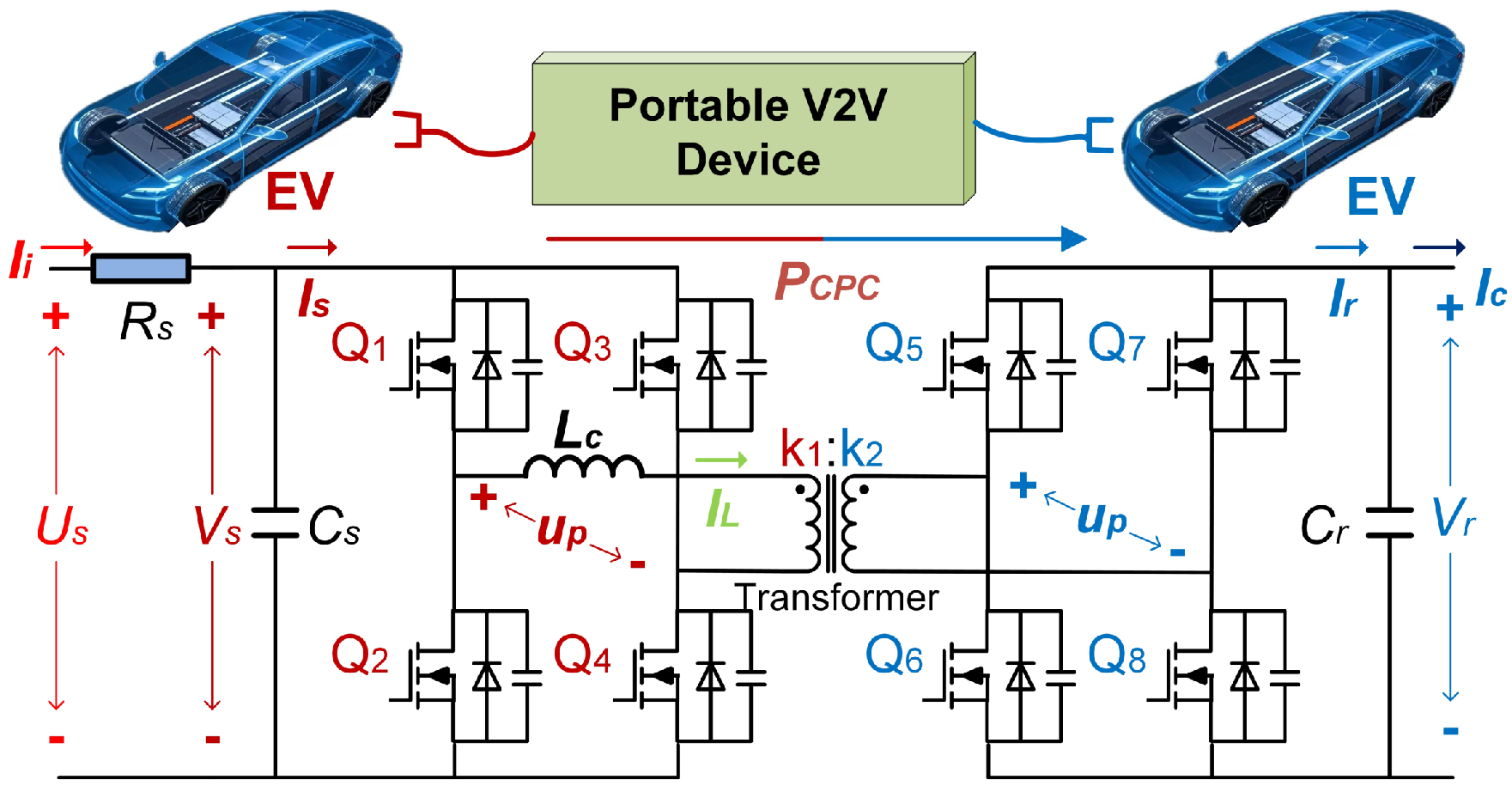
The topology of the DAB-based vehicle–vehicle mutual aid device is shown in Figure 2. U s denotes the battery voltage of the delivered EV. V s denotes the terminal voltage of the sending EV battery and V r denotes the terminal voltage of the receiving EV battery. Equating the receiving side impedance with the thermal energy loss of the transmission device to the primary side translates into an equivalent input resistance of R s . The current fed into the device by the feeding power supply is I s . Similarly, the current flowing out of the device to the receiving end is I r . C s and C r respectively represent the sending and receiving EV battery capacitance. A transformer with a turns ratio of n = k 1 : k 2 is employed to provide isolation between two H bridges. Each bridge works at a switching frequency f s and a 0.5 fixed duty ratio, and the phase-shifting and transformer leakage inductances are combined to give L c .

2.1. DAB Basic Characteristics

The direction of the power flow is determined by the phase-shift ratio between the two bridges. The transmitted power between the bridges is expressed as
P t = n V s V r 2 f s L c d ( d 1 )
where the phase shift within two bridges in a single-phase-shift modulation is d = δ / π and δ is the angular phase shift.
If the system is assumed to be lossless, the input power will be equivalent to the output power. Therefore, the input and output currents can be calculated equivalently using the power transferred by the converter:
I s = n V r 2 f s L c d ( d 1 )
I r = n V s 2 f s L c d ( d 1 )

2.2. System Modeling

The characteristics of voltage and current in the CPL can be described as
I C = P C P C V r ,
where V C represents the voltage at both ends of the CPC and P C P C is the power of the CPC.
The average state-space model for the DAB in Figure 2 is given by
d V s d t = 1 R s C s V s n 2 f s L c C s d ( 1 d ) + U s R s C s
d V r d t = n 2 f s L c C r V s d ( 1 d ) I C C r .
Under steady-state conditions, the energy accumulation in the V2V system’s energy storage components precisely balances the combined energy stored in the input and output capacitors. As derived in Equation (1), the transferred power depends on the input and output terminal capacitor voltages. Therefore, the auxiliary variable x 1 is defined in this paper as
x 1 = 1 2 C s V s 2 + 1 2 C r V r 2
The power transfer control problem can then be equated to an energy storage problem on a capacitor. The derivative of Equation (7) yields
x ˙ 1 = C s V s V ˙ s + C r V r V ˙ r = 1 R s V s 2 + U s V s R s I C V r
The intermediate variables x 2 and w 1 are further introduced as
x 2 = 1 R s V s 2 + U s V s R s
w = I C V r
The derivative of Equation (9) yields
x ˙ 2 = 2 R s V s V ˙ s + U s V ˙ s R s = U s 2 V s R s ( 1 R s C s V s n 2 f s L c C s V r d ( 1 d ) + U s R s C s ) = 2 V s U s R s n 2 f s L c C s V r d ( 1 d ) + U s 2 V s C s R s 2 ( U s V s )
The controller u of the system was designed to be
u = 2 V s U s R s n 2 f s L c C s V r d ( 1 d ) + U s 2 V s C s R s 2 ( U s V s )
The system is modeled as
x ˙ 1 = x 2 + w x ˙ 2 = u
According to Equation (12), the shift ratio d can be obtained as
m = u U s 2 V s C s R s 2 ( U s V s )
d = 0.5 ± 0.5 1 + 8 f s R s L c C s m n V r ( 2 V s U s )
It is worth noting that since the power forward transmission time-shift ratio d is symmetric about 0.5, there is no problem with the expression in Equation (15).
Remark 1.
In order to improve the power density of the device, impedance matching of the V2V system needs to be considered. In the topology shown in Figure 1, the DAB converter inherently performs impedance transformation via its high-frequency transformer and phase-shift ratio d. From Equation (1), the equivalent input impedance seen by the source EV battery is derived as Z in = V s I s = 2 f s L c n V r | d ( d 1 ) | . Similarly, the output impedance at the receiving EV is Z out = V r I r = 2 f s L c n V s | d ( d 1 ) | . It can be seen that the equivalent input and output impedance of the device is determined by d. However, the specific value of d is determined by P r e f . That is, if the V2V device can achieve constant power control, the specific value of P r e f can be obtained by solving m i n | Z i n Z s , b a t t | and m i n | Z o u t Z r , b a t t | , thereby achieving impedance matching through the dynamic adjustment of d, where Z s , b a t t and Z r , b a t t are the time-varying internal impedances of the source/receiving EV batteries. Based on previous research, P r e f can be calculated using impedance matching theory. Under the highest power density conditions, the CPC control process of the V2V system is shown in Figure 3. In this paper, we focus more on the real-time tracking of P r e f in the V2V device rather than on solving the specific value of P r e f . Specifically, Z s , b a t t and Z r , b a t t can be converted to the primary side together, which is equivalent to an input impedance R s for the ease of calculation.
Remark 2.
The multi-stage charging process needs to take into account CC, CPC, and CV control. In the system modeling process (13), the voltage and current characteristics are represented through P C P C = I C V r . It is worth noting that the primary and secondary voltage values can be captured by the sensors. Therefore, a multi-stage control process can be realized by adjusting P C P C . In the CC scenario, P C P C = I C , r e f V r . In the CPC scenario, P C P C = P r e f . In the CV charging scenario, P C P C = I C V r V r , r e f / V r and the I C V r value is represented by FTDO. The values observed through FTDO are presented in the next section. In this way the unification of the multi-stage charging process is achieved through system modeling, and only the value of P C P C needs to be dynamically adjusted when the controller is given a control objective. The following section therefore focuses on how to achieve control in the CPC model.

3. CPC Control Without Current Sensors

To achieve device miniaturization, current sensors are eliminated in this work, with current effects estimated via the observed variable w 1 . The measurable battery terminal voltage U s and input voltage V s serve as system inputs. In this part, the observer is first designed to obtain the accurate w 1 and w 2 , followed by the design of the feedback control method for CPC based on the observed values.

3.1. Design of FTDO

Equation (12) can be written in matrix form as
X ˙ = A X + B U + W ,
where X = [ x 1 , x 2 ] T , U = u , A = [ 0 , 1 ; 0 , 0 ; ] , B = [ 0 , 1 ] T , and W = [ w , 0 ] T .
Assume that w is kth-order differentiable and its kth-order derivative exists with Lipshitz constants l. The intermediate state variable Z is designed as
Z ˙ 1 = V 1 + A X + B U Z ˙ j = V j ( 2 j k )
where Z i = [ Z j , 0 ] T and Z 1 is the special state when j = 1 . Z j denote the intermediate variables introduced as a result of the observation w. The number of systems of equations depends on the order of the Lipshitz constant of the quantity to be observed. The auxiliary variable V was designed as
E ˙ i = λ i L i k ( ϵ i I 2 ) k i k s g n ( ϵ i ) + Z i + 1 ( 1 i k 1 ) V ˙ k = λ k L s g n ( ϵ k )
where λ i = [ λ i , 1 , 0 ; 0 , 0 ; ] , L i = [ l , 0 ; 0 , 0 ; ] , and I 2 denotes the two-dimensional unit matrix. When i = 1 , ϵ 1 = Z 1 X , and when 2 j k , ϵ i = Z i Z i 1 . The matrix multiplication operations presented herein are defined as Hadamard products, denoting element-by-element multiplication between conformable matrices. Finally Z 2 denotes the observation W ^ , Z 3 denotes the observation W ^ ˙ , and so on.
Proof of FTDO. 
Define the observer error as
E 1 = Z 1 X E 2 = Z 2 W E i = Z i W [ i 2 ] ( 3 i k )
By combining Equations (16)–(18), Equation (19) can be transformed into
E ˙ 1 = λ 1 L 1 k | E 1 | k 1 k s g n ( E 1 ) + E 2 E ˙ i = λ i L i k | E i E ˙ i 1 | k i k s g n ( E i E ˙ i 1 ) + E i + 1 ( 2 i k 1 ) E ˙ k = λ k L s g n ( E k E ˙ k 1 )
It follows from [40] that there exists a time constant t f > t 0 such that the observer error E i is finite time stable at that moment. □

3.2. Design of Backstepping Controller

As shown in Figure 2, a functional relationship exists between the EV battery voltage and the input stage voltage of the V2V power conversion system:
U s V s = R s I s
When the demanded charging method is constant power, it can be obtained as
P r e f = V s I i
By combining Equations (21) and (22), the input voltage of the reference can be expressed as
V s , r e f = 0.5 U s + 0.5 U s 2 4 R s P r e f
Meanwhile, the output side voltage reference value V r , r e f is determined by according to the battery state at the receiving end. Furthermore, the control objective of the system can be expressed as
x 1 , r e f = C s V s , r e f 2 2 + C r V r , r e f 2 2
So, the primary goal of the controller role is to achieve x 1 = x 1 , r e f . The error between the system state x 1 and the control objective x 1 , r e f is defined as
e 1 = x 1 , r e f x 1
In order for e 1 to converge to 0, the corresponding Lyapunov function was designed to be
V 1 = 1 2 e 1 2
The derivative with respect to Equation (26) is
V ˙ 1 = e 1 e ˙ 1 = e 1 ( x ˙ 1 , r e f x 2 w ^ ) = p e 1 2
where p is a positive constant. To maintain the system stability through V 1 while satisfying the governing equation, an additional constraint must be imposed on x 2 . Consequently, a new goal regarding x 2 was set to
x 2 , r e f = x ˙ 1 , r e f w ^ + p e 1
The error between the system state x 2 and the control objective x 2 , r e f was defined as
e 2 = x 2 , r e f x 2
The Lyapunov function was designed in the same way as
V 2 = 1 2 e 2 2
The derivative with respect to Equation (30) is
V ˙ 2 = e 2 e ˙ 2 = e 2 ( x ˙ 2 , r e f u ) = e 2 ( x ¨ 1 , r e f w ^ ˙ + p e ˙ 1 u ) = q e 2 2
where q is a positive constant. In order to maintain that Equation (31) holds, the controller u is solved as
u = x ¨ 1 , r e f w ^ ˙ + p e ˙ 1 + q e 2
Remark 3.
Using the controller of Equation (32), the error e 2 can be guaranteed to converge to 0. Meanwhile, from Equation (27), x 2 = x 2 , r e f is a sufficient condition to ensure that the error e 1 converges to 0. Furthermore, the DAB shift compared with the feedback control to achieve the control objective can be completed by combining Equation (15). The control process is shown in Figure 4.

4. Simulation

The simulation results in this section aim to validate the effectiveness of the proposed method. The simulation was performed relying on MATLAB2022a/Simulink. The topology was consistent with Figure 2. The primary and secondary filter capacitances were C s = C r = 1500 μ F . The in-cavity inductance was L c = 43 μ H and the transformer inductance was L T = 8000 μ H . The ratio of turns on the primary and secondary sides of the transformer was 1 : 1 . The switching frequency of the PWM was 50 kHZ. The equivalent loss resistance was R s = 0.2 Ω . Both the primary and secondary power supplies were set as lithium batteries. The rated capacity of the supply side was set to 10 Ah with a nominal voltage of 750 V, the cutoff and fully charged voltages were 720 V and 780 V, respectively. The rated capacity of the receiving side was set to 10 Ah with a nominal voltage of 450 V, the cutoff and fully charged voltages were 430 V and 470 V, respectively. The simulation was verified using the observer design and multi-stage charging.
Case 1: Verification of FTDO for variable power cases.
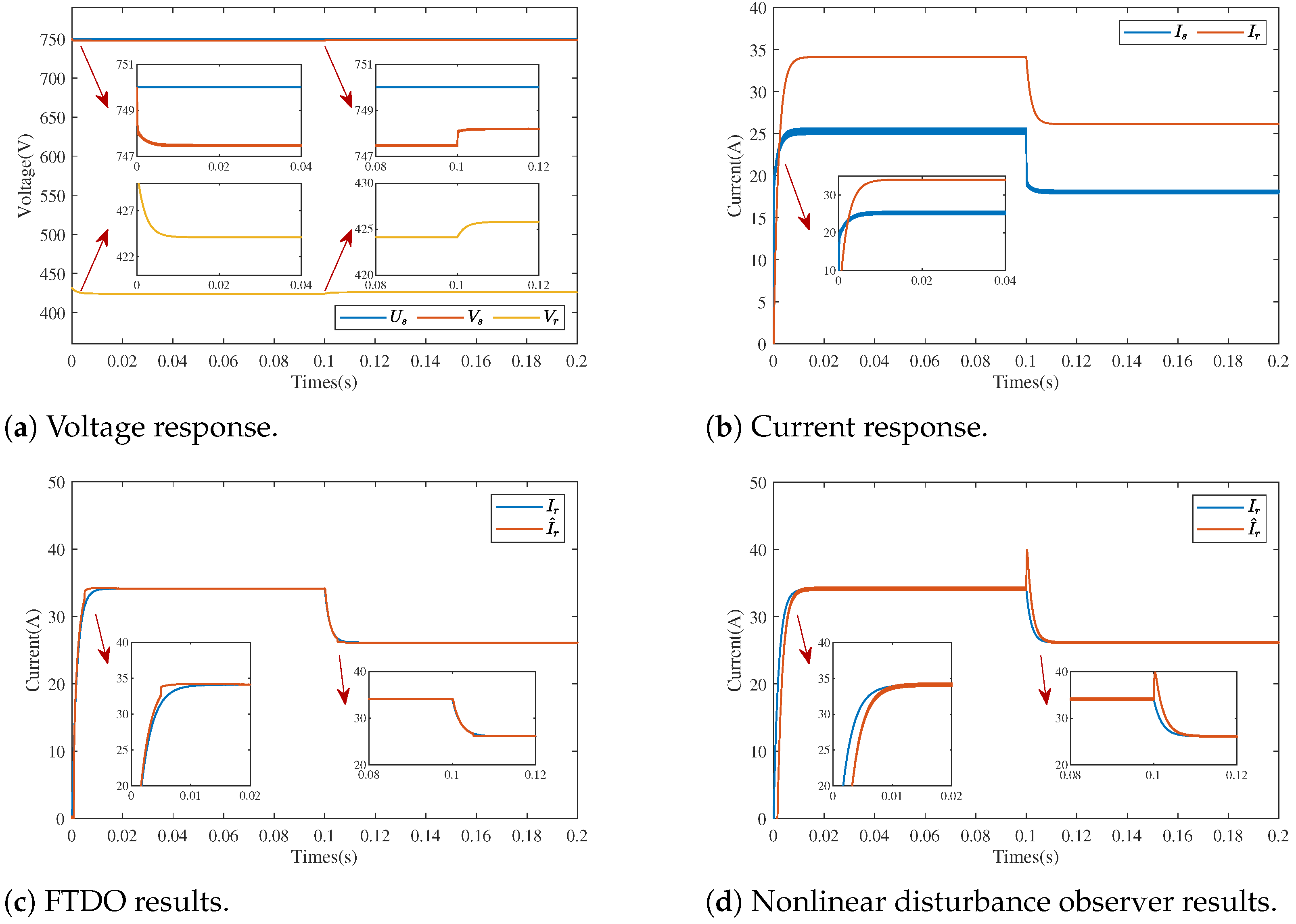
To validate the performance of the proposed observer under current sensors conditions, the controller effectiveness was tested under variable power operation. Simulations were conducted using the proposed method, where sampled values were directly employed instead of the observer. The simulation results are shown in Figure 5: the system started at 0 s with a reference power of 15 kW, which changed to 11 kW at 0.1 s. The voltage and current waveforms demonstrated that the proposed method achieved precise constant power control while maintaining system observability, with no significant voltage spikes observed at either the power source or receiving ends. As evidenced in Figure 5c, the proposed FTDO maintained fast and accurate observation during both transient processes with different power references and steady-state operation. A comparative analysis with Figure 5d revealed that the conventional nonlinear disturbance observer exhibited noticeable overshoot and delay during the dynamic processes, while the FTDO demonstrated superior observation speed and accuracy. Therefore, the proposed method outperformed the conventional approaches and was proved fully capable of supporting current-sensorless operation.
Case 2: CC-to-CPC switchover process validation.
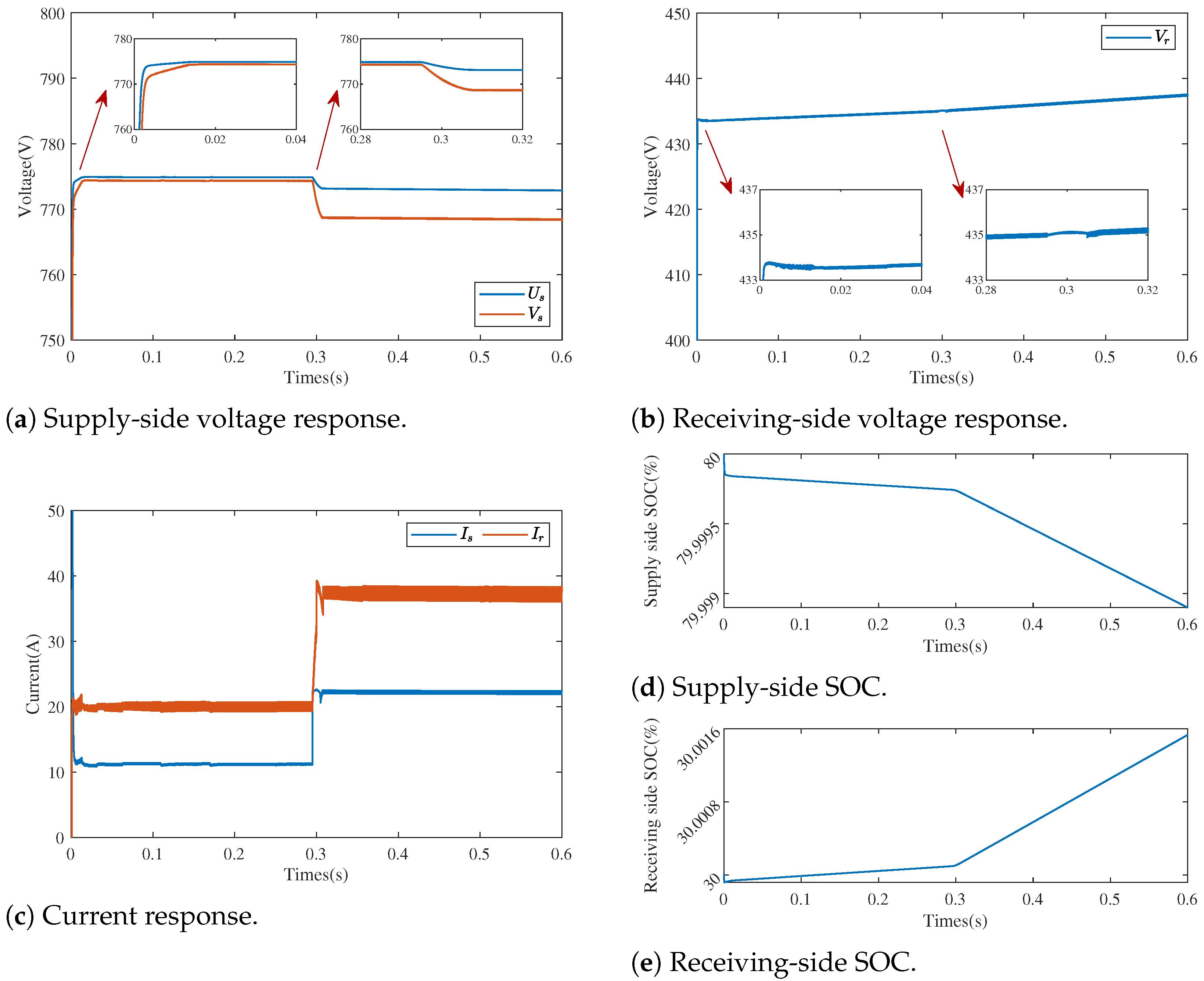
Based on the observer and the proposed control method, the simulation verification of charging mode switching was carried out. The scenario was set up so that the recipient battery was first subjected to CC charging, with a mode change to CPC at 0.3 s. The traditional PI control generated a current spike exceeding 20 A at the 0.3 s switching moment, which caused voltage drops on both sides. The reference power value of CPC was 16 kW. The simulations were set up as two groups: under PI control with a voltage–current double closed loop and under the proposed method as shown in Figure 6 and Figure 7, respectively. The simulation results show that the proposed method was able to achieve the control objective during the CC to CPC switching. Compared with the PI control, both the voltage and current changed more smoothly and the switching process avoided spikes.
Case 3: CPC-to-CV switchover process validation.
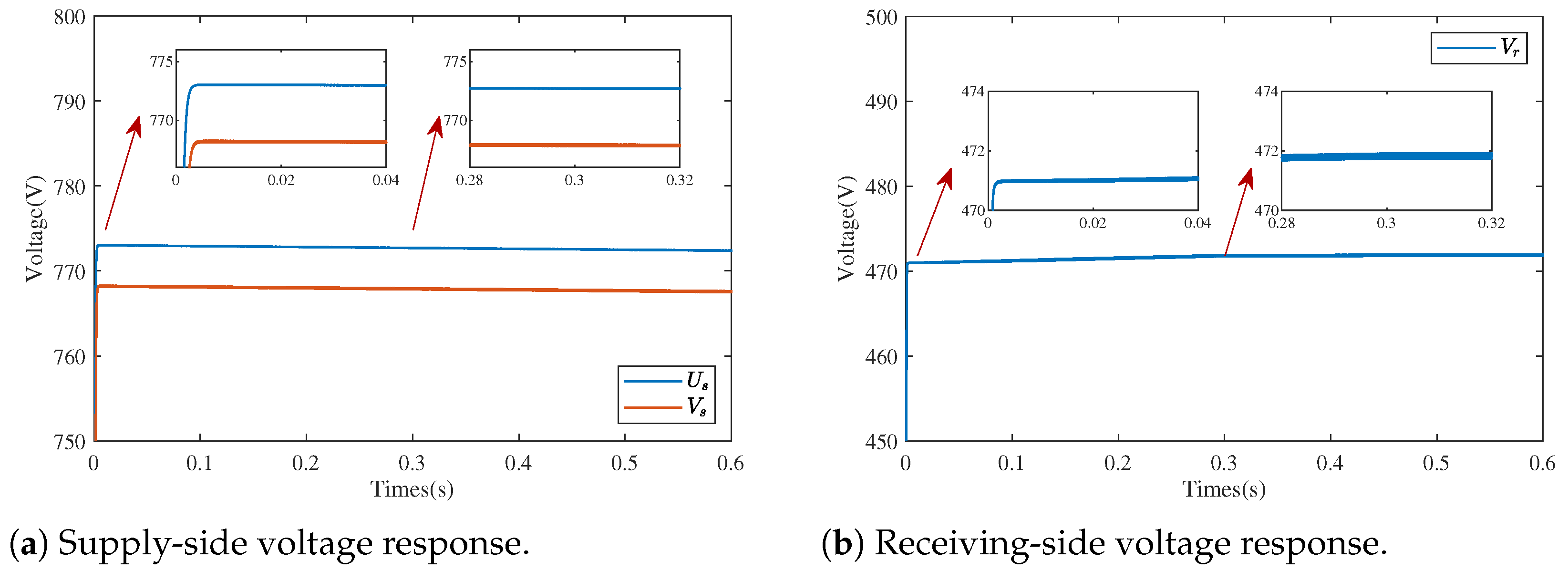
Similar to Case 2, simulations were performed to verify the effect of mode switching during the transition from CPC to CV, as shown in Figure 8 and Figure 9. First, the device adopted the charging mode of CPC and switched to CV mode at 0.3 s. The PI control caused continuous ±8 V voltage oscillations at the receiving end after switching (convergence time > 50 ms). The reference power of the CPC was set to 16 k W and the output voltage value of CV was set to 472 V. The smooth voltage and current transitions achieved by the proposed method confirmed its enhanced control capability. This approach exhibited lower harmonic distortion and prevented voltage transients during the mode transitions compared with the conventional PI control.

5. Experiments

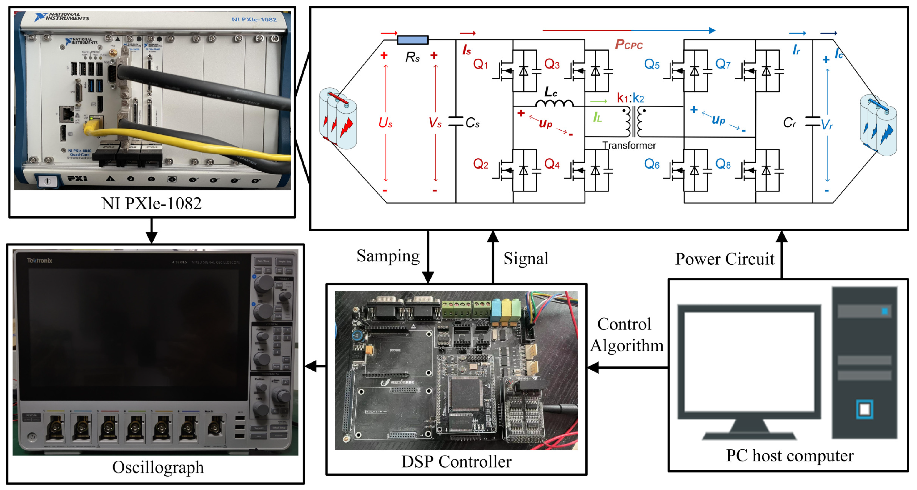
To comprehensively evaluate the proposed power-balancing approach, extended experimental validation was conducted. The test platform architecture and control implementation are detailed in Figure 10. The experimental platform consisted of a PC host computer, DSP controller TMS320F28335 (Sourced from the United States), NI PXle1082 (Sourced from the United States), and Oscillograph MSO56 (Sourced from the United States). The core of the hardware control system was the NI realtime simulator, whose main functions included sensor signal processing and control commands. In particular, the NI PXle1082 ran the power system of RIETES. The DSP was responsible for carrying out the implementation of the algorithm. The PC host was responsible for running the simulation control strategy and the construction of the V2V main circuit. The experimental parameters were consistent with those in the simulation.
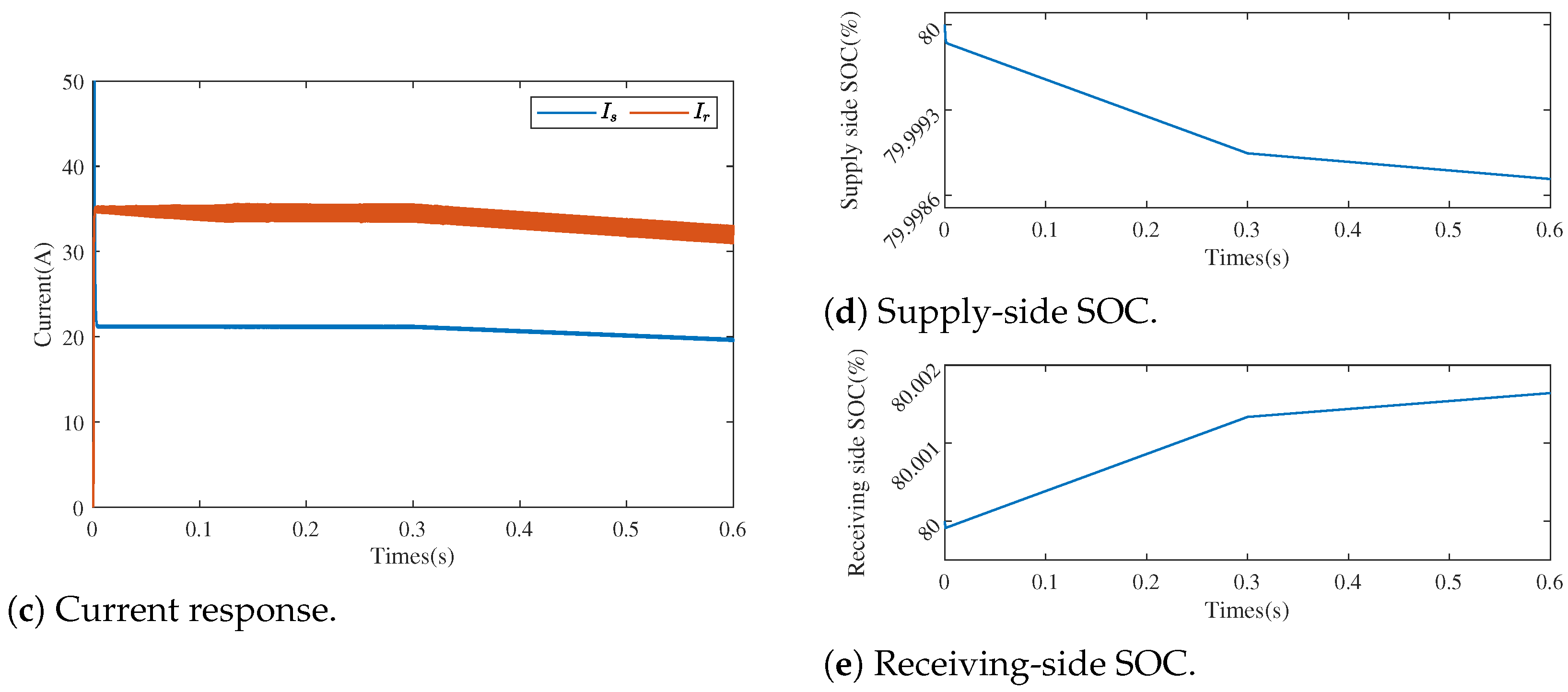
The specific experimental parameters remained consistent with those employed in the simulation system. The experiments were centered around multi-stage charging validation. Similar to the previous section, the experiments were set up as CC-to-CPC switching and CPC-to-CV switching, as shown in Figure 11 and Figure 12. As shown in Figure 11, the seamless transition from CC to CPC was demonstrated by the fact that at the 0.3 s switching moment, the conventional PI control generated a current spike of more than 20 A, which led to a bilateral voltage drop. In contrast, our approach achieved a smooth migration of the current to the steady state within 10 ms while limiting the voltage fluctuation to less than 2 V, which confirmed the ability of the unified model to eliminate mode-switching disturbances. Similarly, from Figure 12, it is clear that where the PI control caused sustained ±8 V oscillations (>50 ms convergence), our approach stabilized to a 472 V reference within 15 ms while maintaining constant power characteristics, which demonstrated effective suppression of power–voltage coupling effects. Compared with the PI control, the proposed method ensured smoother mode switching with superior performance. The results validate the effectiveness of constant power control in resolving the challenging V2V multi-mode transition.

6. Conclusions

This paper addresses the CPC control challenges in V2V systems by proposing a nonlinear hierarchical control strategy based on DAB converters. Through the establishment of a unified dynamic model for the CV-CPC-CC three-stage charging process, the multi-stage control mode switching is transformed into a CPC control problem under varying power reference values. Furthermore, the integration of a FTDO not only enhances the power density of the system but also improves the dynamic response speed compared with previous studies. By incorporating backstepping control theory, precise power tracking and global stability are achieved under bilateral voltage disturbances. The methodology effectively resolves nonlinear instability caused by strong power–voltage coupling in CPC mode, providing theoretical support for high-power-density and low-cost V2V systems. Future research will be extended to multi-port DAB topologies and hybrid energy dispatch scenarios integrating V2V and V2G operations.

Author Contributions

Conceptualization, H.Z.; Methodology, H.Z.; Software, X.Z.; Validation, X.Z.; Formal analysis, H.L.; Investigation, H.L.; Data curation, H.L.; Writing—original draft, L.Z.; Writing—review & editing, L.Z. All authors have read and agreed to the published version of the manuscript.

Funding

This research received no external funding.

Data Availability Statement

The original contributions presented in this study are included in the article. Further inquiries can be directed to the corresponding authors.

Conflicts of Interest

The authors declare no conflicts of interest.

References

  1. Un-Noor, F.; Padmanaban, S.; Mihet-Popa, L.; Mollah, M.N.; Hossain, E. A Comprehensive Study of Key Electric Vehicle (EV) Components, Technologies, Challenges, Impacts, and Future Direction of Development. Energies 2017, 10, 1217. [Google Scholar] [CrossRef]
  2. Sanguesa, J.A.; Torres-Sanz, V.; Garrido, P.; Martinez, F.J.; Marquez-Barja, J.M. A Review on Electric Vehicles: Technologies and Challenges. Smart Cities 2021, 4, 372–404. [Google Scholar] [CrossRef]
  3. Nyamathulla, S.; Dhanamjayulu, C. A Review of Battery Energy Storage Systems and Advanced Battery Management System for Different Applications: Challenges and Recommendations. J. Energy Storage 2024, 86, 111179. [Google Scholar] [CrossRef]
  4. Vengatesan, S.; Jayakumar, A.; Sadasivuni, K.K. FCEV vs. BEV—A short overview on identifying the key contributors to affordable & clean energy (SDG-7). Energy Strateg. Rev. 2024, 53, 101380. [Google Scholar] [CrossRef]
  5. International Energy Agency. Global EV Outlook 2023. Available online: https://www.iea.org/reports/global-ev-outlook-2023 (accessed on 1 July 2024).
  6. Xu, J.; Cai, X.; Cai, S.; Shao, Y.; Hu, C.; Lu, S.; Ding, S. High-Energy Lithium-Ion Batteries: Recent Progress and a Promising Future in Applications. Energy Environ. Mater. 2023, 6, e12450. [Google Scholar] [CrossRef]
  7. He, Z.; Huang, Y.; Liu, H.; Geng, Z.; Li, Y.; Li, S.; Deng, W.; Zou, G.; Hou, H.; Ji, X. Anode materials for fast charging sodium-ion batteries. Nano Energy 2024, 129, 109996. [Google Scholar] [CrossRef]
  8. Khalatbarisoltani, A.; Zhou, H.; Tang, X.; Kandidayeni, M.; Boulon, L.; Hu, X. Energy Management Strategies for Fuel Cell Vehicles: A Comprehensive Review of the Latest Progress in Modeling, Strategies, and Future Prospects. IEEE Trans. Intell. Transp. Syst. 2024, 25, 14–32. [Google Scholar] [CrossRef]
  9. Wang, R.; Liu, H.; Li, M.-J.; Sun, Q.; Li, X.; Wang, P. Fast Charging Control Method for Electric Vehicle-to-Vehicle Energy Interaction Devices. IEEE Trans. Transp. Electrif. 2023, 9, 4941–4950. [Google Scholar] [CrossRef]
  10. Cao, Y.; Cui, J.; Liu, S.; Li, X.; Zhou, Q.; Hu, C. A Holistic Review on E-Mobility Service Optimization: Challenges, Recent Progress, and Future Directions. IEEE Trans. Transp. Electrif. 2024, 10, 3712–3741. [Google Scholar] [CrossRef]
  11. Wen, J.; Gan, W.; Chu, C.-C.; Wang, J.; Jiang, L. Cooperative V2G-enabled vehicle-to-vehicle sharing in energy and reserve markets: A coalitional approach. Appl. Energy 2024, 376, 124311. [Google Scholar] [CrossRef]
  12. Xu, Y.; Ge, X.; Guo, R.; Shen, W. Online Soft Short-Circuit Diagnosis of Electric Vehicle Li-Ion Batteries Based on Constant Voltage Charging Current. IEEE Trans. Transp. Electrif. 2023, 9, 2618–2627. [Google Scholar] [CrossRef]
  13. Duru, K.K.; Karra, C.; Venkatachalam, P.; Betha, S.A.; Madhavan, A.A.; Kalluri, S. Critical Insights Into Fast Charging Techniques for Lithium-Ion Batteries in Electric Vehicles. IEEE Trans. Device Mater. Reliab. 2021, 21, 137–152. [Google Scholar] [CrossRef]
  14. Ji, D.; Chen, L.; Ma, T.; Wang, J.; Liu, S.; Ma, X.; Wang, F. Research on adaptability of charging strategy for electric vehicle power battery. J. Power Sources 2019, 437, 226911. [Google Scholar] [CrossRef]
  15. Chen, G.-J.; Chung, W.-H. Evaluation of Charging Methods for Lithium-Ion Batteries. Electronics 2023, 12, 4095. [Google Scholar] [CrossRef]
  16. Xu, F.; Wong, S.-C.; Tse, C.K. Overall Loss Compensation and Optimization Control in Single-Stage Inductive Power Transfer Converter Delivering Constant Power. IEEE Trans. Power Electron. 2022, 37, 1146–1158. [Google Scholar] [CrossRef]
  17. Wang, R.; Sun, Q.; Hu, W.; Li, Y.; Ma, D.; Wang, P. SoC-Based Droop Coefficients Stability Region Analysis of the Battery for Stand-Alone Supply Systems with Constant Power Loads. IEEE Trans. Power Electron. 2021, 36, 7866–7879. [Google Scholar] [CrossRef]
  18. Iam, I.-W.; Choi, C.-K.; Lam, C.-S.; Mak, P.-I.; Martins, R.P. A Constant-Power and Optimal-Transfer-Efficiency Wireless Inductive Power Transfer Converter for Battery Charger. IEEE Trans. Ind. Electron. 2024, 71, 450–461. [Google Scholar] [CrossRef]
  19. Dong, X.; Zhang, H.; Xie, X.; Ming, Z. Data-Driven Distributed H Current Sharing Consensus Optimal Control of DC Microgrids via Reinforcement Learning. IEEE Trans. Circuits Syst. I 2024, 71, 2824–2834. [Google Scholar] [CrossRef]
  20. Chen, J.; Xu, Y.; Lu, H.; Yan, Z.; Yu, Z.; Li, Q. Fixed Frequency LCC Resonant Converter Modeling and Optimal Design for High-Voltage Capacitor Charging Power Supply in Constant Power Control. IEEE Trans. Ind. Appl. 2023, 59, 4287–4299. [Google Scholar] [CrossRef]
  21. Zhang, K.; Zhang, P.; Du, H.; Yan, Z.; Song, B.; Hu, A.P. Robust Control of IPT System for Constant Current Charging Under Multiple Parameter Perturbations. IEEE Trans. Ind. Appl. 2022, 58, 1168–1178. [Google Scholar] [CrossRef]
  22. Wang, R.; Sun, Q.; Sun, C.; Zhang, H.; Gui, Y.; Wang, P. Vehicle-Vehicle Energy Interaction Converter of Electric Vehicles: A Disturbance Observer Based Sliding Mode Control Algorithm. IEEE Trans. Veh. Technol. 2021, 70, 9910–9921. [Google Scholar] [CrossRef]
  23. Nkembi, A.A.; Santoro, D.; Ahmad, F.; Kortabarria, I.; Cova, P.; Sacchi, E.; Delmonte, N. Novel Droop-Based Techniques for Dynamic Performance Improvement in a Linear Active Disturbance Rejection Controlled-Dual Active Bridge for Fast Battery Charging of Electric Vehicles. Energies 2024, 17, 5171. [Google Scholar] [CrossRef]
  24. Wang, Z.; Su, X.; Zeng, N.; Jiang, J. Overview of Isolated Bidirectional DC–DC Converter Topology and Switching Strategies for Electric Vehicle Applications. Energies 2024, 17, 2434. [Google Scholar] [CrossRef]
  25. Liu, L.; Tang, J.; Yang, S.; Qian, B.; Wu, Q.; Zhou, M.; Jun, P.; Zhang, F. An Ultra-High Voltage AC/DC Isolated Matrix Converter Applied to V2G Electric Vehicle Charging Piles. Int. J. Circuit Theory Appl. 2024. [Google Scholar] [CrossRef]
  26. Gupta, J.; Singh, B. A Fully Bridgeless Bidirectional Single Stage Isolated Battery Charger-Cum-Domestic Inverter System for LEVs Application. IEEE Trans. Ind. Appl. 2024, 60, 7193–7205. [Google Scholar] [CrossRef]
  27. Cheng, Z.; He, L.; Zhou, H. Optimal Triple-Phase-Shift Modulation Strategy for Wide-Gain High-Efficiency Bidirectional CLLC Converter. IEEE Trans. Transp. Electrif. 2025, 11, 5867–5879. [Google Scholar] [CrossRef]
  28. Wang, X.; Wei, X.; Chen, Q.; Dai, H. A Novel System for Measuring Alternating Current Impedance Spectra of Series-Connected Lithium-Ion Batteries with a High-Power Dual Active Bridge Converter and Distributed Sampling Units. IEEE Trans. Ind. Electron. 2021, 68, 7380–7390. [Google Scholar] [CrossRef]
  29. Everts, J.; Krismer, F.; Van den Keybus, J.; Driesen, J.; Kolar, J.W. Optimal ZVS Modulation of Single-Phase Single-Stage Bidirectional DAB AC–DC Converters. IEEE Trans. Power Electron. 2014, 29, 3954–3970. [Google Scholar] [CrossRef]
  30. Jiang, Y.; Li, Y.; Yang, J.; Shu, X. A Review of Research on Dual-Side Control Methods for Magnetic Coupling Wireless Power Transfer Systems Based on Dual-Active Bridge Converters. Electronics 2024, 13, 4765. [Google Scholar] [CrossRef]
  31. Demirci, O.; Taskin, S.; Schaltz, E.; Demirci, B.A. Review of battery state estimation methods for electric vehicles—Part I: SOC estimation. J. Energy Storage 2024, 87, 111435. [Google Scholar] [CrossRef]
  32. Ding, C.; Ding, S.; Wei, X.; Ji, X.; Sun, J.; Mei, K. Disturbance-Observer-Based Barrier Function Adaptive Sliding Mode Control for Path Tracking of Autonomous Agricultural Vehicles with Matched-Mismatched Disturbances. IEEE Trans. Transp. Electrif. 2024, 10, 6748–6760. [Google Scholar] [CrossRef]
  33. Zheng, C.; Dragičević, T.; Blaabjerg, F. Current-Sensorless Finite-Set Model Predictive Control for LC-Filtered Voltage Source Inverters. IEEE Trans. Power Electron. 2020, 35, 1086–1095. [Google Scholar] [CrossRef]
  34. Chen, X.; Xu, G.; Han, H.; Liu, D.; Sun, Y.; Su, M. Light-Load Efficiency Enhancement of High-Frequency Dual-Active-Bridge Converter Under SPS Control. IEEE Trans. Ind. Electron. 2021, 68, 12941–12946. [Google Scholar] [CrossRef]
  35. Pal, P.; Behera, R.K.; Muduli, U.R. Eliminating Current Sensor Dependencies in DAB Converters Using a Luenberger Observer-Based Hybrid Approach. IEEE Trans. Ind. Appl. 2024, 60, 6380–6392. [Google Scholar] [CrossRef]
  36. Tiwary, N.; Naik, V.N.; Panda, A.K.; Narendra, A.; Lenka, R.K. A Robust Voltage Control of DAB Converter with Super-Twisting Sliding Mode Approach. IEEE J. Emerg. Sel. Top. Ind. Electron. 2023, 4, 288–298. [Google Scholar] [CrossRef]
  37. Zhang, L.; Yang, G.-H. Observer-based adaptive decentralized fault-tolerant control of nonlinear large-scale systems with sensor and actuator faults. IEEE Trans. Ind. Electron. 2019, 66, 8019–8029. [Google Scholar] [CrossRef]
  38. Çelik, D.; Ahmed, H.; Meral, M.E. Kalman Filter-Based Super-Twisting Sliding Mode Control of Shunt Active Power Filter for Electric Vehicle Charging Station Applications. IEEE Trans. Power Deliv. 2023, 38, 1097–1107. [Google Scholar] [CrossRef]
  39. Wang, B.; Luo, C.; Yu, Y.; Wang, G.; Xu, D. Antidisturbance Speed Control for Induction Machine Drives Using High-Order Fast Terminal Sliding-Mode Load Torque Observer. IEEE Trans. Power Electron. 2018, 33, 7927–7937. [Google Scholar] [CrossRef]
  40. Zhu, J.; Li, S. Adaptive output feedback command filter control based on extreme learning machine for nonaffine time delay systems with input saturation. Int. J. Syst. Sci. 2024, 56, 1060–1080. [Google Scholar] [CrossRef]
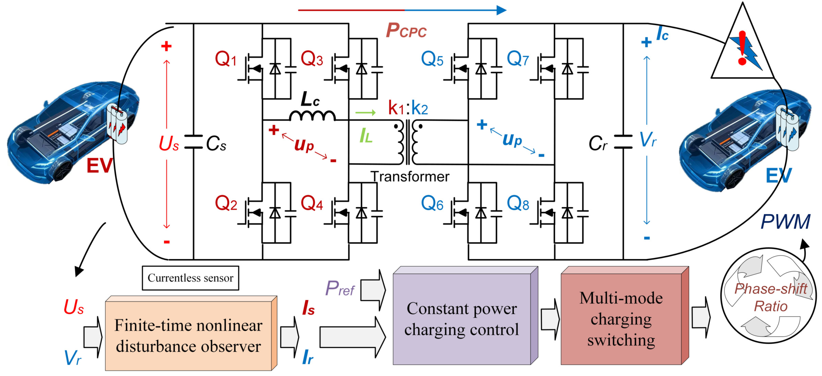
Figure 1. Main contents and contributions of the proposed V2V method.
Processes 13 01999 g001
Figure 2. Isolated portable V2V device with DAB topology.
Processes 13 01999 g002
Figure 3. V2V impedance matching process.
Processes 13 01999 g003
Figure 4. Control block diagram of DAB in CPC mode.
Processes 13 01999 g004
Figure 5. Response of the system when the rated power was changed from 15 kW to 11 kW.
Processes 13 01999 g005
Figure 6. System response during CC-to-CPC switchover under PI control.
Processes 13 01999 g006
Figure 7. System response during CC-to-CPC switchover under the proposed control.
Processes 13 01999 g007
Figure 8. System response during CPC-to-CV switchover under PI control.
Processes 13 01999 g008
Figure 9. System response during the CPC-to-CV switchover under the proposed control.
Processes 13 01999 g009aProcesses 13 01999 g009b
Figure 10. The experiment set.
Processes 13 01999 g010
Figure 11. System response during CC-to-CPV switchover.
Processes 13 01999 g011
Figure 12. System response during CPC-to-CV switchover.
Processes 13 01999 g012
Disclaimer/Publisher’s Note: The statements, opinions and data contained in all publications are solely those of the individual author(s) and contributor(s) and not of MDPI and/or the editor(s). MDPI and/or the editor(s) disclaim responsibility for any injury to people or property resulting from any ideas, methods, instructions or products referred to in the content.