Article

Parametric Effects of Mixing Channel Geometry on Entrainment Characteristics of Ejector in R410A Heat Pump Systems

College of Architecture and Civil Engineering, North China University of Science and Technology, Tangshan 063210, China
*
Authors to whom correspondence should be addressed.
Processes 2025, 13(6), 1933; https://doi.org/10.3390/pr13061933
Submission received: 29 April 2025 / Revised: 11 June 2025 / Accepted: 11 June 2025 / Published: 18 June 2025
(This article belongs to the Section Process Control and Monitoring)

Abstract

The two-phase ejector has gained prominence in heat pump systems as a device that effectively mitigates throttling losses through expansion work recovery. This investigation employs three-dimensional computational fluid dynamics (CFD) simulations to analyze the parametric effects of the mixing channel geometry on the entrainment characteristics in an R410A ejector. After validating the model according to the experimental data, the parameter analysis was carried out, and four key geometric parameters were changed within a certain range: the nozzle exit position (NXP = 13–19 mm), the pre-mixing channel convergent angle (CA = 20–60°), the diameter ratio (DDR = 5.0–7.1), and the length-to-diameter ratio (LDR = 8.9–12.4). Multi-variable optimization studies revealed optimal geometric configurations at NXP = 17 mm (about 3.5Dmix), CA = 30°, DR = 6.4, and LDR = 11.1, yielding an optimized mass entrainment ratio enhancement of 23.6% compared to baseline designs. This research provides actionable guidelines for the design of high-efficiency ejector components for heat pump applications.

1. Introduction

The inherent thermodynamic irreversibility of isenthalpic throttling processes remains a primary limiting factor in terms of vapor compression heat pump efficiency, typically accounting for 20–30% of the total system losses [1]. Recent advancements in expansion work recovery technologies have positioned two-phase ejectors as a promising technological intervention for energy dissipation mitigation, demonstrating COP improvements up to 21.6% in optimized R744 transcritical systems [2]. Furthermore, extensive studies have demonstrated the theoretical feasibility of ejector-enhanced subcritical heat pump cycles, with experimental validations reporting COP enhancements of 6.5–38% across various operating conditions [3,4,5,6,7].
The ejector operates through four sequenced components: the primary nozzle, secondary inlet, mixing channel (comprising the premixing convergent section and constant-area duct), and diffuser (Figure 1). Its performance is influenced by three aspects: the geometric configuration, operational parameters, and working fluid properties. Under fixed thermodynamic conditions, geometric optimization becomes the principal determinant of the entrainment characteristics.
Many investigations aimed at optimizing the ejector geometry via experiments and numerical methods have been conducted in transcritical R744 heat pump systems. In 2011, Elbel’s experimental characterization of R744 transcritical refrigeration configurations revealed that the diffuser divergence angles and mixing lengths (Lmix) have a significant impact on the system’s performance [8]. Nakagawa et al. [9] quantified the operational penalties of suboptimal Lmix configurations, identifying up to about 10% COP degradation in R744 transcritical refrigeration configurations. Yazdani et al. [10] also found that, when the mixing channel diameter (Dmix) deviates from the optimum value, the ejector efficiency decreases significantly. Computational advancements have enabled precise geometric optimization through multi-parameter CFD analyses. In 2012, Banasiak et al. [11] performed a study combining numerical and experimental work to evaluate how critical dimensional variables, particularly Lmix, Dmix, and the diffuser angles, impact R744 heat pump performance. In 2016, Palacz et al. [12] achieved a 2% performance improvement through the CFD-based Dmix optimization of an R744 ejector. In 2020, Dong et al. [13] demonstrated that the ejector mass entrainment rate (MER) remains unaffected by Lmix below 80 mm, but, beyond this critical threshold, extended dimensions weaken the suction efficiency and operational stability. In 2021, Ameur et al. [14] found that it is necessary to reduce Dmix and the throat diameter to enhance the ejector efficiency. In 2022, Kakkirala et al. [15] found that, when Dmix is increased from 0.1 m to 0.13 m, the MER is from 1.12 to 1.64. In addition, Feng et al. [16] determined through CFD simulations that, when Amix/Apn, out = 8.3 and Lmix/Dmix = 8.1, the ejector performance reaches the optimal level.
The parameter nozzle exit position (NXP) quantifies the axial distance separating the primary nozzle outlet from the mixing channel’s entry plane in constant-area ducts. In 2011, Lee et al. [17] identified the existence of an optimal NXP in transcritical R744 air conditioning systems through experimental investigations, which improved the performance of the system by 15%. Their research further revealed that there is an optimal value for Dmix. Liu et al. [18,19,20] conducted experiments to investigate the nozzle exit positioning effects on a transcritical R744 ejector air conditioning system, demonstrating its critical influence on the flow dynamics and thermodynamic efficiency. Furthermore, the correlations between the NXP and Dmix and between Lmix and Dmix of the mixing channel were presented. In 2014, Banasiak et al. [21] identified that the primary sources of thermodynamic irreversibility in transcritical R744 ejectors originate from two key phenomena: shock wave trains at the primary nozzle exit and turbulent mixing processes within the mixing channel. Their findings underscore the critical importance of optimizing both the structural configuration and geometric parameters of the mixing channel to maximize the ejector performance. In 2017, Palacz et al. [22] developed a geometry optimization methodology for R744 ejectors, incorporating six key design parameters: Lmix, Dmix, the pre-mixing channel length, the primary nozzle outlet diameter (Dpn,out), the primary nozzle divergent angle, and the secondary inlet convergent angle. Their optimization results demonstrated a significant 6% improvement in ejector efficiency, highlighting the substantial performance gains achievable through precise geometric tuning. In 2017, Zhu et al. [23] conducted experimental investigations utilizing advanced flow visualization techniques to characterize the expansion angle dynamics and the underlying mixing mechanisms of two-phase supersonic R744 flows within ejectors. Their study provided critical insights into the complex fluid interactions occurring in the mixing channel. Zheng and Deng [24] demonstrated that the ejector efficiency exhibits a positive correlation with the area ratio (At/Amix) and an inverse relationship with the NXP. In 2018, Suo [25] conducted a parameter optimization study on the supercritical R744 ejection system and determined the optimal configuration at NXP = 9 mm and Lmix = 124 through thermodynamics. Compared with the refrigeration system, the COP increased by 37.8%. In 2022, Li and Deng [26] numerically investigated the influence of the mixing channel width and length on the ejector performance, identifying distinct optima for each geometric parameter. Deviations from these optimal values were shown to degrade the performance through two primary mechanisms: vortex generation and amplified frictional dissipation. Subsequently, their research revealed that the NXP significantly affects the flow dynamics, with moderate reductions suppressing suction vortices while accelerating secondary flows, thereby enhancing the overall ejector efficiency [27]. In 2023, Liu et al. [28] found that Dmix exhibited the strongest correlation with the performance metrics, followed by Lmix and the NXP. Yan et al. [29] corroborated this parametric significance ranking, reinforcing the critical roles of the mixing channel dimensions and nozzle positioning. In 2024, Yu et al. [30] employed transient numerical analysis to determine the optimal area ratio (Amix/At) for heat pump applications, establishing a range of 2.65–4.87 upon operational conditions. In 2025, Wang et al. [31] found that, when the NXP—the interaction distance between the primary flow and the secondary flow—is significantly reduced, it results in a decrease in the ejector’s inhalation performance. In 2025, Long et al. [32] discovered that eccentricity effects are geometry-dependent, interacting with four key parameters: the NXP, Dmix, Lmix, and the diffuser angle. Their analysis quantified the inverse relationships between the eccentricity sensitivity and both the mixer dimensions and diffuser angle.
Despite extensive research on transcritical systems, little attention has been paid to geometric optimization studies for subcritical refrigeration ejectors. The geometric parameters governing ejector performance exhibit fundamentally different behaviors in these systems due to R410A’s thermophysical properties. R744’s transcritical expansion is shock-driven with a rapid phase change, whereas R410A’s subcritical flow exhibits inertia-dominated evaporation, requiring geometric adaptation to manage momentum transfer and the vaporization efficiency. These differences necessitate refrigerant-specific ejector optimization protocols. In 2014, Hu et al. [33] found that an appropriate NXP is conducive to improving the ejection efficiency of the system through a study of the R410A air conditioning system. In 2016, Yan et al. [34] found that the NXP had a more obvious impact on the ejector performance than Lmix by studying the R134a ejector expansion refrigeration system. However, Bilir Sag and Ersoy [35] reported contrasting findings for R134a systems, where the COP variation with NXP changes was negligible, suggesting that no significant optimal NXP exists under their tested conditions. In 2017, Huang et al. [36] experimentally verified that a small NXP value can improve the ejector performance in the R134a system by improving the shock wave interaction. Furthermore, Jeon et al. [37] established a hybrid channel diameter (Dmix = 9 mm) for the R410A system based on a comprehensive seasonal performance coefficient, achieving a 7.5% efficiency improvement.
This comprehensive literature review highlights that the mixing channel geometric parameters, particularly the NXP, CA, Dmix, and Lmix values, represent critical design variables for ejector performance optimization. However, four significant research gaps emerge from current studies. Firstly, despite extensive numerical and experimental investigations of two-phase ejectors for diverse refrigerants, empirical datasets for R410A—one of the most widely adopted working fluids in heat pump systems—remain remarkably scarce. Consequently, the underlying mechanisms governing the interactions between the geometric parameters and ejector performance are yet to be elucidated. Secondly, while existing investigations have predominantly employed experimental methodologies, the complex two-phase flow phenomena inherent in ejector operation, including shock wave interactions, turbulent mixing, and phase change dynamics, pose substantial challenges for experimental characterization. Thirdly, computational fluid dynamics (CFD) has demonstrated considerable potential in overcoming these limitations, as evidenced by successful applications in ejector performance analysis [38,39,40,41]. However, few of them have indicated how each ejector geometry parameter affects its entrained performance. Fourthly, despite these advantages, the current CFD literature exhibits a notable deficiency in parametric sensitivity analysis. The above review identified only one comprehensive study (Baek et al. [42]) that has quantitatively evaluated individual geometric parameters’ effects (NXP, Dmix, and Lmix) on the entrainment performance in subcritical R134a systems. This gap is especially pronounced for R410A refrigerant systems, which dominate commercial heat pump applications but remain understudied in ejector research.
This study aimed to numerically investigate the influence of key mixing channel geometric parameters on the entrainment performance of a two-phase ejector utilizing the R410A refrigerant, which is widely employed in modern vapor compression systems. A three-dimensional CFD model incorporating real fluid properties and phase change phenomena was developed and validated. The systematic optimization of four critical geometric parameters (NXP, CA, DR, and LDR) was carried out. The optimum values of the geometric parameters were explored, with a particular emphasis on maximizing the entrainment performance to enhance the energy efficiency of heat pump systems.

2. Materials and Methods

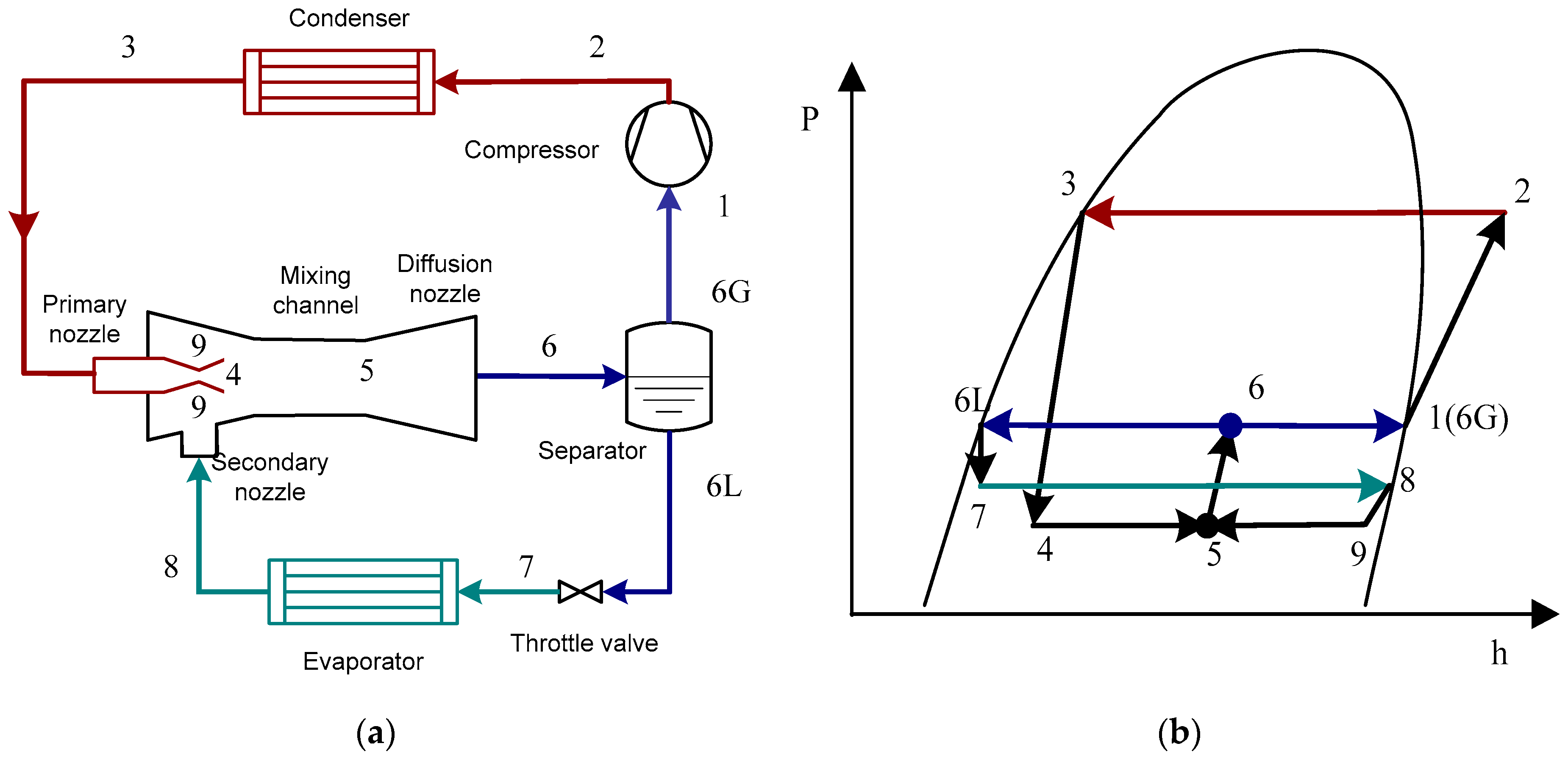
A layout diagram of the ejector expansion refrigeration cycle and the corresponding p-h diagram are shown in Figure 2.
The mass entrainment ratio (MER) is defined as the mass flow rate ratio of secondary to primary flows, expressed as
MER = MFRsn/MFRpn
The compressor work consumption per unit mass flow rate is
wcom = h2h1
The evaporator refrigerating capacity per unit mass flow rate is
qeva = MER(h8h7)
The cycle cooling coefficient of performance can be expressed as
COP = qeva/wcom = MER(h8h7)/(h2h1)
It can be seen from the analysis of formulas (2)–(4) that, when the evaporation pressure and the outlet pressure of the ejector are constant, the cycle COP is proportional to the ejector entrainment ratio. Therefore, the larger the entrainment ratio is, the greater the COP of the cycle will be. Furthermore, the variations in the component efficiency and the whole ejector efficiency with the geometric parameters are similar to the MER [43]. Thus, this paper mainly aims to improve the MER of the ejector by optimizing the structural parameters of the ejector.
The assumptions of this study are as follows:
(1)
Steady-state operating conditions;
(2)
The walls of the ejector are adiabatic and non-slipping;
(3)
Thermodynamic equilibrium between phases;
(4)
Equal velocity fields for liquid and vapor phases;
(5)
A uniform temperature distribution.

2.1. Governing Equations

The fluid is modeled as a compressible Newtonian real fluid with turbulence effects accounted for through the k-ε model. Steady-state simulations are performed for each operating condition, resulting in the elimination of temporal derivatives from the governing equations. The conservation equations are expressed as follows.
The mass equation is
· ρ U = 0
The momentum equation is
· ρ U U = p + · τ
Following the methodology established by Smolka et al. [38], the conventional temperature-dependent formulation of the energy equation is reformulated using the specific enthalpy as the primary thermodynamic variable. This approach eliminates the need for explicit temperature calculations in phase change regions and provides greater numerical stability during two-phase flow simulations. The modified energy conservation equation is presented as follows:
· ρ U H = · λ h T p h λ h T p h p T p + τ · U
The total enthalpy of the two-phase mixture is defined as follows:
H = h + U 2 2
According to the Homogeneous Equilibrium Model (HEM), a balance between internal energy and mechanical energy is assumed for the two phases. Therefore, all thermodynamic properties and transport characteristics of the two-phase fluid depend on the pressure and specific enthalpy:
{ p c , c p , λ , μ } = f ( p , h )
For turbulence modeling, the standard k-ε model is implemented based on its established reliability in ejector flow simulations, as evidenced by multiple validation studies [22,32,42,44].
The turbulent viscosity (μt) is expressed as
μ t = ρ C μ k 2 ε
The turbulent kinetic energy (k) equation is as follows:
· ρ k U = · μ + μ t σ k k + G k + G b ρ ε Y M + S k
The dissipation rate (ε) equation is as follows:
· ρ ε U = · μ + μ t σ ε ε + C 1 ε ε k G k + C 3 ε G b C 2 ε ρ ε 2 k + S ε

2.2. Computational Technique

The computational simulations employed a pressure-based solver with a second-order upwind discretization scheme for all transport equations. The pressure–velocity coupling was resolved using the SIMPLE algorithm, which has demonstrated excellent performance in compressible flow applications. During the simulations, the maximum convergence residual for the energy equation was set to be below 10−6, while the residuals for the other equations were limited to less than 10−5.
The thermophysical properties of R410A were rigorously implemented using the NIST REFPROP 9.0 database [45] through ANSYS Fluent 2020 R2 user-defined functions (UDFs). The implementation strategy accounted for phase-dependent requirements. Liquid-phase properties (density ρ, specific heat cp, thermal conductivity λ, dynamic viscosity μ) were calculated as temperature-dependent functions via piecewise cubic polynomials. Vapor-phase properties were treated as real fluid properties, using the pressure and temperature as independent variables. A bicubic interpolation scheme was implemented via UDFs, with the Peng–Robinson equation of state resolving compressibility effects. In the two-phase region, the Homogeneous Equilibrium Model (HEM) was employed, assuming thermodynamic equilibrium between phases over small length scales [38,39].
The two-phase mixture properties were calculated as [46]
ρ = 1 x / ρ g + ( 1 x ) ρ l
c p = 1 x / c p , g + ( 1 x ) c p , l
λ = 1 x / λ g + ( 1 x ) λ l
μ = 1 x / μ g + ( 1 x ) μ l

2.3. Geometry, Grid, and Boundary Conditions

The baseline ejector was designed to operate under the following thermodynamic conditions:
  • Primary inlet pressure: 2.13 MPa (subcooled liquid);
  • Secondary inlet pressure: 0.75 MPa (saturated vapor);
  • Discharge pressure: 0.85 MPa (two-phase mixture).
The geometric parameters of the baseline ejector configuration, derived through coupled analytical modeling and experimental correlations, are presented in Table 1.
Table 2 summarizes the corresponding boundary conditions applied to the computational domain.
The computational domain was discretized using structured hexahedral elements generated with ANSYS ICEM 2020R2 as illustrated in Figure 3. To accommodate the complex flow features, the geometry was partitioned into three distinct zones: the primary nozzle, secondary nozzle, and mixing diffuser section. The standard k-ε turbulence model was employed, with careful consideration of the near-wall treatment limitations inherent to its boundary layer formulation. The selection of wall functions was guided by three critical factors: the flow regime characteristics, local equilibrium requirements, and computational grid constraints. After systematic evaluation, the standard wall function was implemented due to its reduced sensitivity to the near-wall mesh resolution, validated for y+ values between 30 and 300. This approach optimizes the balance between solution accuracy and computational economy for industrial-scale parametric studies.
For discretization schemes, a second-order upwind formulation was applied to the convection terms, while gradients were computed via the least squares cell-based method. Turbulence boundary conditions were specified as follows: an inlet turbulence intensity of 10% with the hydraulic diameter based on the nozzle geometry; outlet conditions employed zero-gradient specification for turbulence variables; and all walls utilized scalable wall functions with adiabatic no-slip conditions.
A systematic grid independence study was conducted, employing three mesh resolutions (coarse mesh: 302,789 elements, medium mesh: 407,894 elements, fine mesh: 507,890 elements). The analysis revealed minimal variation (<1.5%) in the MER predictions between the medium and fine resolutions, suggesting solution convergence. Based on this assessment, the medium resolution was selected as optimal, balancing computational accuracy with resource efficiency. Given the geometric variations across optimized ejectors, the mesh counts varied within 384,734–458,567 elements. All configurations maintained strict quality criteria.

2.4. Model Validation

The numerical model and computational methodology were validated against experimental data from Jeon et al. [37] under identical geometric configurations and operating conditions (medium capacity, compressor speed 2340 rpm, fixed condensing pressure at 2763 kPa, and evaporation pressure at 1184 kPa). As shown in Figure 4, there are minor discrepancies between the numerical predictions and experimental data concerning both the MER and the primary mass flow rate (MFR). The relative error range of the primary MFR is 8.3% to 17.1%, and the absolute error range is 0.08 to 0.37. The relative error range of the MER is −8.9% to 12.9%, and the absolute error range is 0.01 to 0.07. The observed discrepancies may be attributed to the idealized boundary conditions in the simulations or minor deviations in the two-phase flow assumptions. Despite these variations, the validation errors were within a reasonable range for two-phase CFD standards in the literature, as shown in Table 3. The MFR predictions for R744 exhibit significantly greater variability in the relative error compared to R290. This discrepancy primarily arises from two fundamental factors: (1) the non-ideal compressibility behavior of R744 near its critical point introduces numerical stiffness in solving the governing equations; (2) the flash evaporation process in R744 occurs more abruptly than in R290, rendering the solution highly sensitive to the grid resolution at phase interfaces. In contrast, R290’s smoother pressure–temperature thermodynamic profile enhances the numerical stability, thereby reducing the prediction variability. In addition, the observed differences in the MFR errors across various turbulence models remain statistically insignificant, suggesting that model selection plays a secondary role to the refrigerant-specific thermodynamic properties in the prediction accuracy. The validation results demonstrate satisfactory model accuracy for engineering applications, establishing confidence in subsequent parametric studies.

3. Results and Discussion

3.1. Ejector Flow Dynamics

Figure 5 presents the axial distributions of the pressure, velocity, and gas volume fraction along the ejector centerline. The primary flow exhibits a two-stage pressure reduction: a gradual decrease followed by rapid expansion near the throat, culminating in a minimum pressure of 0.23 MPa at the nozzle exit, corresponding to a total pressure drop of 1.9 MPa. This pressure differential creates a 0.5 MPa driving force (from 0.75 MPa at the secondary inlet to 0.25 MPa in the pre-mixing channel) that enables vapor entrainment. The flow subsequently stabilizes in the pre-mixing channel, with negligible pressure variation (Δp < 0.01 MPa), followed by progressive pressure recovery through the constant-area mixing channel (0.02 MPa increase) and diffuser section (0.03 MPa rise), yielding a total pressure regain of 0.05 MPa. This pressure evolution demonstrates the effective momentum transfer between the primary and secondary streams while maintaining favorable pressure lift characteristics.
The primary flow exhibits a progressive velocity increase, followed by rapid acceleration through the nozzle throat, reaching 40 m/s at this critical cross-section. Subsequent expansion in the divergent section further accelerates the flow to a peak velocity of 114 m/s near the nozzle exit. This supersonic jet undergoes significant deceleration (ΔV = 89 m/s) upon entering the pre-mixing channel due to turbulent mixing with the entrained secondary flow. The velocity continues to decrease linearly through the constant-area mixing channel, stabilizing at 25 m/s at its outlet. This conversion of kinetic energy to pressure energy, as evidenced by the inverse relationship with the pressure profile, confirms the effective momentum transfer between the primary and secondary streams, with the observed 71% velocity reduction corresponding to the previously reported 0.05 MPa pressure recovery.
The subcooled liquid refrigerant from the condenser undergoes rapid expansion in the primary nozzle, initiating flash evaporation upstream of the throat, where the phase change rate peaks. It reveals that the vapor fraction increases from 0 at the inlet to 0.6 at the throat, reaching 0.93 by the nozzle exit. This high-velocity two-phase jet subsequently interacts with the saturated vapor (quality = 1.0) entrained through the secondary inlet in the pre-mixing channel. The mixing process yields a near-homogeneous mixture (vapor fraction = 0.94) at the mixing channel exit, with subsequent slight condensation (Δvapor fraction = 0.09) occurring in the diffuser due to pressure recovery. The discharged working fluid maintains equilibrium quality of 0.85, indicating efficient energy conversion through the expansion–mixing–compression process.

3.2. Effect of Nozzle Exit Position

Four nozzle exit positions (NXP = 13, 15, 17, and 19 mm) were investigated to analyze their influence on the MER. As shown in Figure 6, the MER exhibits an optimum at NXP = 17 mm (MER = 0.78), with suboptimal performance at both lower and higher positions. Below the optimum NXP, the MER increases gradually with the NXP, while, beyond 17 mm, it decreases sharply. This optimal NXP corresponds to approximately 3.5 times the mixing channel diameter (Dmix), aligning closely with the findings of Liu et al. [19,20], but slightly exceeding the values reported by Baek et al. [42] and Zhu et al. [48].
Velocity field visualization (Figure 7) reveals the underlying fluid dynamics governing this behavior. For an NXP increasing from 13 to 17 mm, the jet angle decreases, resulting in an enhanced compression effect at the entrance of the mixing channel, and the secondary flow is entrained more efficiently, while the interaction distance of the primary fluid and the secondary fluid is longer, resulting in an increase of 22% in the average velocity and a significant improvement in the MER. However, beyond the optimal position, the jet impinges on the mixing channel wall, forming a vortex and energy dissipation; excessive frictional losses along the extended flow path cause a 15% reduction in effective kinetic energy transfer. The optimum NXP thus represents a balance between a sufficient momentum transfer duration and minimal energy dissipation, maximizing entrainment while maintaining flow efficiency. These findings corroborate established ejector optimization principles while providing specific design criteria for R410A systems.

3.3. Effect of Pre-Mixing Channel Convergent Angle

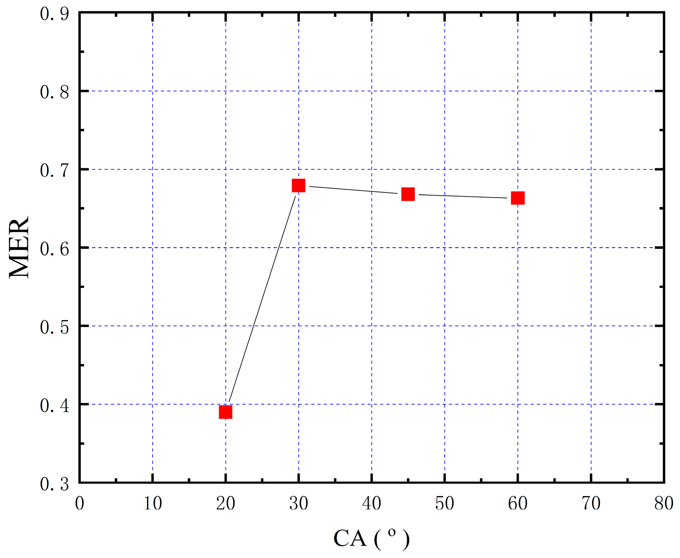
The MER exhibits significant dependence on the pre-mixing channel convergent angle (CA) while maintaining constant inlet/outlet diameters. As illustrated in Figure 8, the MER initially increases with the CA, peaking at 0.69 for CA = 30°, followed by a gradual decline at larger angles. This non-monotonic relationship confirms the existence of an optimal CA for the maximization of the ejector entrainment performance. The 30° optimum represents a balance between flow guidance and energy preservation, consistent with established two-phase ejector design principles.
The velocity distributions (Figure 9) and streamline patterns (Figure 10) reveal the underlying fluid dynamics in the ejectors. Small CAs (<30°) restrict secondary flow passage, increasing the frictional losses by approximately 25% and reducing the entrainment efficiency. Optimal CA conditions (30°) provide a sufficient flow area for effective momentum transfer while maintaining flow guidance. Excessive CAs (>30°) cause a local high-pressure zone at the inlet of the mixing channel, hindering the suction of the secondary flow, and promote flow separation and vortex formation (Figure 9). The stronger the vortex, the greater the backflow, causing energy dissipation and reducing the effective entrainment capacity. The observed MER variation thus results from competing effects between flow area availability and viscous dissipation, with the 30° configuration achieving an optimal compromise between these factors.

3.4. Effect of Diameter Ratio

The diameter ratio (DDR), defined as Dmix/Dt, was investigated for four values (5.0, 5.7, 6.4, and 7.1) while maintaining a constant throat diameter. As shown in Figure 11, the MER demonstrates a clear optimum at DDR = 6.5 (MER = 0.71), with suboptimal performance at both smaller and larger ratios. Below the optimum DDR, the MER increases gradually, while, beyond this value, it decreases sharply. This optimal configuration agrees well with Baek et al. [35].
Velocity field visualization (Figure 12) reveals the underlying mechanisms governing this behavior. At low DDR values (<6.5), the restricted flow area limits both secondary stream entrainment and primary–secondary momentum transfer, reducing the mean secondary velocity by approximately 35%. Optimal DDR conditions maximize the interfacial contact area, enhancing momentum exchange and increasing the secondary flow velocity by 28%. However, excessive DDR values (>6.5) cause the cross-sectional area of the mixing channel to be excessively large; the working fluid loses the constraint of the boundary layer, the ejector fluid returns due to the pressure difference, and substantial wall friction losses are introduced, as evidenced by the 22% velocity reduction in the mixing channel. The observed MER variation thus results from competing effects between enhanced momentum transfer and increased viscous dissipation, with the 6.5 DDR representing the optimal balance between these factors for R410A heat pump applications.

3.5. Effect of Length-to-Diameter Ratio

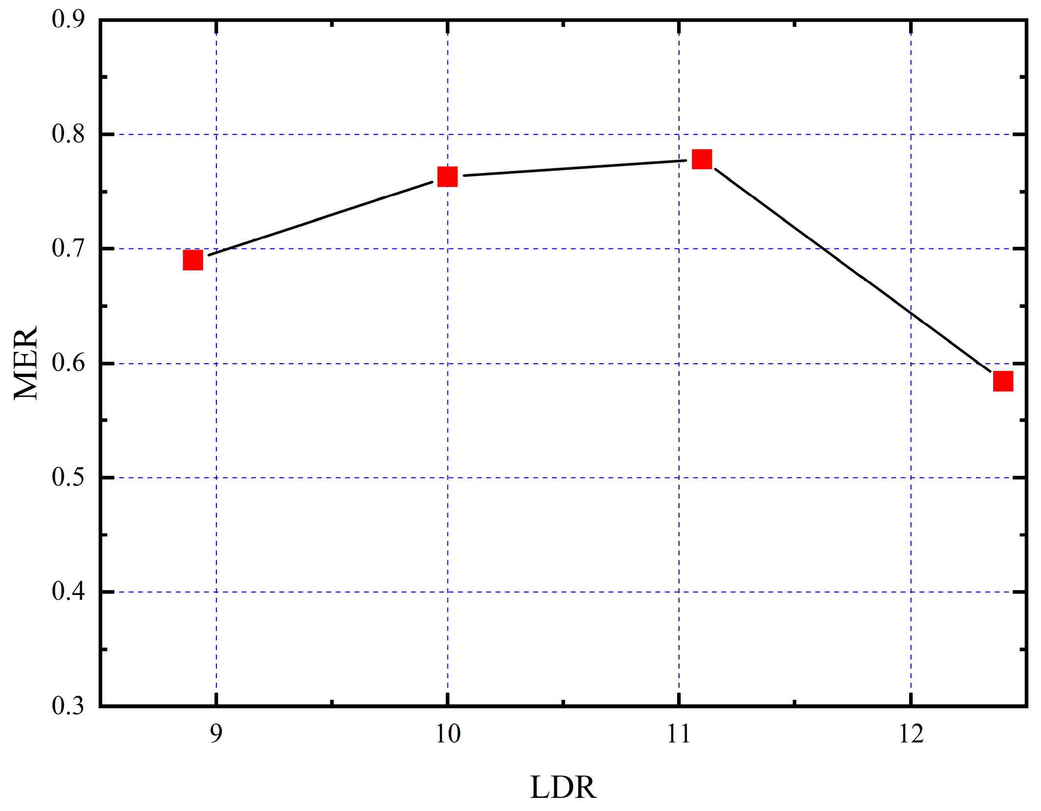
The length-to-diameter ratio (LDR = Lmix/Dmix) was investigated for four values (8.9, 10, 11.1, and 12.4) while maintaining a constant mixing channel diameter. As shown in Figure 13, the MER exhibits a distinct optimum at LDR = 11.1 (MER = 0.78), representing a 28% improvement over the minimum value observed at LDR = 12.4. This non-monotonic relationship, consistent with previous studies [9,11], arises from competing flow mechanisms. Velocity field visualization (Figure 14) reveals that an insufficient mixing length (LDR < 11.1) restricts interfacial momentum transfer due to the limited contact duration, while an excessive length (LDR > 11.1) causes the mixing channel to be too long; shear stress will be avoided significantly, the kinetic energy of the primary fluid will be consumed, and the ability to eject the secondary fluid will be reduced, which introduces substantial frictional losses along the channel walls. The optimal LDR achieves a balance between complete momentum exchange (requiring sufficient residence time) and minimal energy dissipation (necessitating a compact geometry), with the 11.1 ratio providing the ideal compromise for R410A heat pump applications.

3.6. Summary

The values of the specific MER corresponding to changes in the ejector geometry parameters are summarized in Table 4.

4. Conclusions and Limitations

This study numerically investigated the flow characteristics and geometric optimization of a two-phase ejector using R410A as the refrigerant under typical heat pump conditions. A validated CFD model was employed to explore the effects of the mixing channel parameters on the ejector entrainment performance, yielding the following conclusions:
(1)
The CFD simulation results are basically consistent with the experimental data, with relative errors ranging from 8.3% to 17.1% for the primary MFR and −8.9% to 12.9% for the MER.
(2)
The primary nozzle position significantly influences the ejector entrainment performance, with an optimal NXP of 17 mm (≈3.5Dmix) maximizing the MER. Below this optimum, the MER increases gradually with the NXP, while exceeding it causes a sharp decline due to increased frictional losses.
(3)
The convergent angle (CA) exhibits a non-monotonic relationship with the MER, peaking at 30°. This optimum balances flow guidance and energy preservation, while larger angles induce vortex formation and efficiency degradation.
(4)
The diameter ratio (DDR = 6.4) and length-to-diameter ratio (LDR = 11.1) optimize momentum transfer while minimizing energy dissipation in the constant-area mixing channel.
The optimal geometric parameters of a two-phase ejector using R410A as the refrigerant under typical heat pump conditions were determined (NXP = 17 mm, CA = 30°, DDR = 6.4, LDR = 11). While the simulations provided computationally efficient solutions for ejector performance optimization, certain flow phenomena observed in the results warrant discussion:
(1)
The asymmetric attachment of the primary jet to the diffuser walls suggests inherent unsteadiness, consistent with prior LES studies of Venturi flows [49]. Steady-state simulations cannot resolve the following: transient vortex shedding from the primary nozzle, low-frequency oscillations in shear layer reattachment, and time-dependent momentum redistribution in the diffuser. The observed inherent unsteadiness in the ejector flow dynamics implies that practical systems may experience low-frequency oscillations in the MER and ejector efficiency reductions under off-design conditions.
(2)
The k-ε model employs Boussinesq’s eddy viscosity hypothesis, which assumes isotropic turbulence and a local equilibrium. These assumptions introduce some key limitations for ejector flows: anisotropy neglect means that it fails to capture strong streamline curvature in convergent/divergent sections and swirling flows from nozzle asymmetry; the overprediction of the eddy viscosity may result in the underestimation of the separation in diffuser regions.

Author Contributions

Conceptualization, Y.W. and Z.Z. (Zhenying Zhang); methodology, Y.W. and M.Y.; software, Y.W.; validation, Y.W. and Z.Z. (Zhengdao Zhou); formal analysis, Y.L.; investigation, Y.W. and M.Y.; resources, Z.Z. (Zhenying Zhang); data curation, Y.W. and M.Y.; writing—original draft preparation, Y.W. and M.Y.; writing—review and editing, L.C.; visualization, Z.Z. (Zhengdao Zhou); supervision, Y.L., M.Y. and Z.Z. (Zhenying Zhang); project administration, L.C. and Z.Z. (Zhenying Zhang); funding acquisition, Z.Z. (Zhenying Zhang). All authors have read and agreed to the published version of the manuscript.

Funding

This research was funded by the S&T Program of Hebei (20474501D).

Data Availability Statement

The original contributions presented in this study are included in the article. Further inquiries can be directed to the corresponding authors.

Conflicts of Interest

The authors declare no conflicts of interest.

Abbreviations

CAConvergent angle of pre-mixing channel
COPCoefficient of performance
DDRRatio between constant-area mixing channel diameter and primary nozzle throat diameter
LDRRatio between length and constant-area mixing channel diameter
MERMass entrained ratio
MFRMass flow rate, kg s−1
NXPDistance between primary nozzle outlet and constant-area mixing channel, mm
Variables
cpSpecific heat, kJ kg−1 K−1
CμTurbulent viscosity coefficient
C1εTurbulent dissipation rate production term coefficient
C2εTurbulent dissipation rate dissipation term coefficient
C3εBuoyancy effect correction coefficient
DDiameter, mm
hSpecific enthalpy, kJ kg−1
HTotal enthalpy, kJ kg−1
GbGeneration of turbulence kinetic energy due to buoyancy
GkGeneration of turbulence kinetic energy due to mean velocity gradients
kTurbulence kinetic energy
εRate of dissipation
λEffective thermal conductivity, W m−1 K−1
LLength, mm
pPressure, Pa
TTemperature, K
UVelocity vector, m s−1
SUser-defined source term
xVapor mass fraction
YMContribution of fluctuating dilatation in compressible turbulence to overall dissipation rate
τStress tensor, N m−2
μDynamic viscosity, Pa s
μtTurbulent (or eddy) viscosity
Subscripts
pnPrimary nozzle
difDiffuser
snSecondary nozzle
mixMixing channel
inInlet
outOutlet

References

  1. Zhang, Z.; Feng, X.; Tian, D.; Yang, J.; Chang, L. Progress in ejector-expansion vapor compression refrigeration and heat pump systems. Energ. Convers. Manage. 2020, 207, 112529. [Google Scholar] [CrossRef]
  2. Yang, T.; Yang, Y.; Zou, H.; Tian, C.; Butrymowicz, D. Comprehensive performance evaluation on a transcritical CO2 ejector-expansion heat pump system. Appl. Therm. Eng. 2024, 254, 123697. [Google Scholar] [CrossRef]
  3. Besagni, G. Ejectors on the cutting edge: The past, the present and the perspective. Energy 2019, 170, 998–1003. [Google Scholar] [CrossRef]
  4. Zou, L.; Yu, J. 4E assessment of ejector-enhanced R290 heat pump cycle with a sub-cooler for cold region applications. Energy 2024, 298, 131369. [Google Scholar] [CrossRef]
  5. Pottker, G.; Hrnjak, P. Ejector in R410A vapor compression systems with experimental quantification of two major mechanisms of performance improvement: Work recovery and liquid feeding. Int. J. Refrig. 2015, 50, 184–192. [Google Scholar] [CrossRef]
  6. Spitzenberger, J.; Mohammed, R.H.; Ismael, L.; Wang, P.; Ma, H.; Abu-Heiba, A.; Kowalski, S.; Nawaz, K. Experimental performance of ejector heat pump operating in the sub-critical mode. Energ. Convers. Manage. 2023, 278, 116724. [Google Scholar] [CrossRef]
  7. Fingas, R.; Haida, M.; Smolka, J.; Besagni, G.; Bodys, J.; Palacz, M.; Nowak, A.J. Experimental analysis of the air-to-water ejector-based R290 heat pump system for domestic application. Appl. Therm. Eng. 2024, 236, 121800. [Google Scholar] [CrossRef]
  8. Elbel, S. Historical and present developments of ejector refrigeration systems with emphasis on transcritical carbon dioxide air-conditioning applications. Int. J. Refrig. 2011, 34, 1545–1561. [Google Scholar] [CrossRef]
  9. Nakagawa, M.; Marasigan, A.R.; Matsukawa, T.; Kurashina, A. Experimental investigation on the effect of mixing length on the performance of two-phase ejector for CO2 refrigeration cycle with and without heat exchanger. Int. J. Refrig. 2011, 34, 1604–1613. [Google Scholar] [CrossRef]
  10. Yazdani, M.; Alahyari, A.A.; Radcliff, T.D. Numerical modeling of two-phase supersonic ejectors for work-recovery applications. Int. J. Heat Mass Tran. 2012, 55, 5744–5753. [Google Scholar] [CrossRef]
  11. Banasiak, K.; Hafner, A.; Andresen, T. Experimental and numerical investigation of the influence of the two-phase ejector geometry on the performance of the R744 heat pump. Int. J. Refrig. 2012, 35, 1617–1625. [Google Scholar] [CrossRef]
  12. Palacz, M.; Smolka, J.; Kus, W.; Fic, A.; Bulinski, Z.; Nowak, A.J.; Banasiak, K.; Hafner, A.; Cai, W. CFD-based shape optimisation of a CO2 two-phase ejector mixing section. Appl. Therm. Eng. 2016, 95, 62–65. [Google Scholar] [CrossRef]
  13. Dong, J.; Hu, Q.; Yu, M.; Han, Z.; Cui, W.; Liang, D.; Pan, X. Numerical investigation on the influence of mixing chamber length on steam ejector performance. Appl. Therm. Eng. 2020, 174, 115204. [Google Scholar] [CrossRef]
  14. Ameur, K.; Aidoun, Z. Two-phase ejector enhanced carbon dioxide transcritical heat pump for cold climate. Energ. Convers. Manage. 2021, 243, 1144. [Google Scholar] [CrossRef]
  15. Kakkirala, V.; Velayudhan Parvathy, C. Optimized mixing chamber length and diameter of a steam ejector for the application of gas turbine power plant: A computational approach. J. Therm. Anal. Calorim. 2022, 147, 8881–8894. [Google Scholar] [CrossRef]
  16. Feng, X.; Zhang, Z.; Wu, Y.; Tian, D. A parametric study on the effect of mixing chamber for expansion work recovery CO2 ejector. J. Therm. Sci. 2022, 31, 1914–1927. [Google Scholar] [CrossRef]
  17. Lee, J.S.; Kim, M.S.; Kim, M.S. Experimental study on the improvement of CO2 air conditioning system performance using an ejector. Int. J. Refrig. 2011, 34, 1614–1625. [Google Scholar] [CrossRef]
  18. Liu, F.; Groll, E.A.; Ren, J. Comprehensive experimental performance analyses of an ejector expansion transcritical CO2 system. Appl. Therm. Eng. 2016, 98, 1061–1069. [Google Scholar] [CrossRef]
  19. Liu, F.; Li, Y.; Groll, E.A. Performance enhancement of CO2 air conditioner with a controllable ejector. Int. J. Refrig. 2012, 35, 1604–1616. [Google Scholar] [CrossRef]
  20. Liu, F.; Groll, E.A.; Li, D. Investigation on performance of variable geometry ejectors for CO2 refrigeration cycles. Energy 2012, 45, 829–839. [Google Scholar] [CrossRef]
  21. Banasiak, K.; Palacz, M.; Hafner, A.; Buliński, Z.; Smołka, J.; Nowak, A.J.; Fic, A. A CFD-based investigation of the energy performance of two-phase R744 ejectors to recover the expansion work in refrigeration systems: An irreversibility analysis. Int. J. Refrig. 2014, 40, 328–337. [Google Scholar] [CrossRef]
  22. Palacz, M.; Smolka, J.; Nowak, A.J.; Banasiak, K.; Hafner, A. Shape optimisation of a two-phase ejector for CO2 refrigeration systems. Int. J. Refrig. 2017, 74, 212–223. [Google Scholar] [CrossRef]
  23. Zhu, Y.; Wang, Z.; Yang, Y.; Jiang, P.-X. Flow visualization of supersonic two-phase transcritical flow of CO2 in an ejector of a refrigeration system. Int. J. Refrig. 2017, 74, 354–361. [Google Scholar] [CrossRef]
  24. Zheng, L.; Deng, J. Research on CO2 ejector component efficiencies by experiment measurement and distributed-parameter modeling. Energ. Convers. Manage. 2017, 142, 244–256. [Google Scholar] [CrossRef]
  25. Suo, J. Simulation and Experimental Study on Performance of Two-Stage Throttling Transcritical CO2 Ejector Refrigeration System. Master’s Thesis, Tianjin University of Commerce, Tianjin, China, 2018. [Google Scholar]
  26. Li, Y.; Deng, J. Numerical investigation on the performance of transcritical CO2 two-phase ejector with a novel non-equilibrium CFD model. Energy 2022, 238, 121995. [Google Scholar] [CrossRef]
  27. Li, Y.; Deng, J.; He, Y. Numerical study on the interaction of geometric parameters of a transcritical CO2 two-phase ejector using response surface methodology and genetic algorithm. Appl. Therm. Eng. 2022, 214, 118799. [Google Scholar] [CrossRef]
  28. Liu, G.; Zhao, H.; Deng, J.; Wang, L.; Zhang, H. Performance improvement of CO2 two-phase ejector by combining CFD modeling, artificial neural network and genetic algorithm. Int. J. Refrig. 2023, 154, 151–167. [Google Scholar] [CrossRef]
  29. Yan, J.; Li, Z.; Zhang, H. Investigation on key geometries optimization and effect of variable operating conditions of a transcritical R744 two-phase ejector. Appl. Therm. Eng. 2023, 230, 120733. [Google Scholar] [CrossRef]
  30. Yu, M.; Zou, L.; Yu, J. Numerical investigation on the effect of area ratio on an adjustable ejector for heat pump dryer based on dynamic mesh. Energy 2024, 308, 132876. [Google Scholar] [CrossRef]
  31. Wang, Y.; Guo, X.; Liu, X.; Shi, C. Jet performance exploration of an ejector for multi-parallel ejector air curtain. Int. Commun. Heat Mass Transf. 2025, 164, 108868. [Google Scholar] [CrossRef]
  32. Long, J.; Yu, B.; Wang, D.; Liu, C.; Shi, J.; Chen, J. A novel relaxation drift model for simulating liquid-vapor momentum non-equilibrium in two-phase ejectors. Case Stud. Therm. Eng. 2023, 52, 103758. [Google Scholar] [CrossRef]
  33. Hu, J.; Shi, J.; Liang, Y.; Yang, Z.; Chen, J. Numerical and experimental investigation on nozzle parameters for R410A ejector air conditioning system. Int. J. Refrig. 2014, 40, 338–346. [Google Scholar] [CrossRef]
  34. Yan, J.; Lin, C.; Cai, W.; Chen, H.; Wang, H. Experimental study on key geometric parameters of an R134A ejector cooling system. Int. J. Refrig. 2016, 67, 102–108. [Google Scholar] [CrossRef]
  35. Bilir Sag, N.; Ersoy, H.K. Experimental investigation on motive nozzle throat diameter for an ejector expansion refrigeration system. Energy Convers. Manag. 2016, 124, 1–12. [Google Scholar] [CrossRef]
  36. Huang, K.; Guo, X.; Zhang, P. Influence of Structural Parameters of Two-throat Nozzle Ejector on Performance of Two-phase Flow Ejector Refrigeration System. Energy Procedia 2017, 105, 5091–5097. [Google Scholar] [CrossRef]
  37. Jeon, Y.; Jung, J.; Kim, D.; Kim, S.; Kim, Y. Effects of ejector geometries on performance of ejector-expansion R410A air conditioner considering cooling seasonal performance factor. Appl. Energ. 2017, 205, 761–768. [Google Scholar] [CrossRef]
  38. Smolka, J.; Bulinski, Z.; Fic, A.; Nowak, A.J.; Banasiak, K.; Hafner, A. A computational model of a transcritical R744 ejector based on a homogeneous real fluid approach. Appl. Math Model 2013, 37, 1208–1224. [Google Scholar] [CrossRef]
  39. Palacz, M.; Smolka, J.; Fic, A.; Bulinski, Z.; Nowak, A.J.; Banasiak, K.; Hafner, A. Application range of the HEM approach for CO2 expansion inside two-phase ejectors for supermarket refrigeration systems. Int. J. Refrig. 2015, 59, 251–258. [Google Scholar] [CrossRef]
  40. Haida, M.; Smolka, J.; Hafner, A.; Palacz, M.; Banasiak, K.; Nowak, A.J. Modified homogeneous relaxation model for the R744 trans-critical flow in a two-phase ejector. Int. J. Refrig. 2018, 85, 314–333. [Google Scholar] [CrossRef]
  41. Lee, M.S.; Lee, H.; Hwang, Y.; Radermacher, R.; Jeong, H.-M. Optimization of two-phase R600a ejector geometries using a non-equilibrium CFD model. Appl. Therm. Eng. 2016, 109, 272–282. [Google Scholar] [CrossRef]
  42. Baek, S.; Ko, S.; Song, S.; Ryu, S. Numerical study of high-speed two-phase ejector performance with R134a refrigerant. Int. J. Heat Mass Tran. 2018, 126, 1071–1082. [Google Scholar] [CrossRef]
  43. Bai, T.; Lu, Y.; Wen, Z.; Yu, J. Numerical study on the structural optimization of R290 two-phase ejector with a non-equilibrium CFD model. Int. J. Refrig. 2025, 170, 287–301. [Google Scholar] [CrossRef]
  44. Ameur, K.; Aidoun, Z.; Ouzzane, M. Expansion of subcooled refrigerant in two-phase ejectors with no flux induction. Exp. Therm. Fluid Sci. 2017, 82, 424–432. [Google Scholar] [CrossRef]
  45. Lemmon, E.; Huber, M.; McLinden, M. NIST Standard Reference Database 23: Reference Fluid Thermodynamic and Transport Properties—REFPROP, 9th ed.; Standard Reference Data Program; National Institute of Standards and Technology: Gaithersburg, MD, USA, 2010. [Google Scholar]
  46. Bodys, J.; Smolka, J.; Palacz, M.; Haida, M.; Banasiak, K.; Nowak, A.J. Effect of turbulence models and cavitation intensity on the motive and suction nozzle mass flow rate prediction during a non-equilibrium expansion process in the CO2 ejector. Appl. Therm. Eng. 2022, 201, 117743. [Google Scholar] [CrossRef]
  47. Li, C.; Liu, F.; He, M.; Liu, Y. Numerical study of a CO2 swirl ejector with lubricating oil. Int. J. Refrig. 2024, 165, 446–465. [Google Scholar] [CrossRef]
  48. Zhu, Y.; Huang, Y.; Li, C.; Zhang, F.; Jiang, P.X. Experimental investigation on the performance of transcritical CO2 ejector–expansion heat pump water heater system. Energ. Convers. Manage. 2018, 167, 147–155. [Google Scholar] [CrossRef]
  49. Semlitsch, B.; Laurendeau, E.; Mihəescu, M. Steady-State and Unsteady Simulations of a High Velocity Jet into a Venturi Shaped Pipe. In Proceedings of the 4th Joint US-European Fluids Engineering Summer Meeting, Chicago, IL, USA, 3–7 August 2014. [Google Scholar]
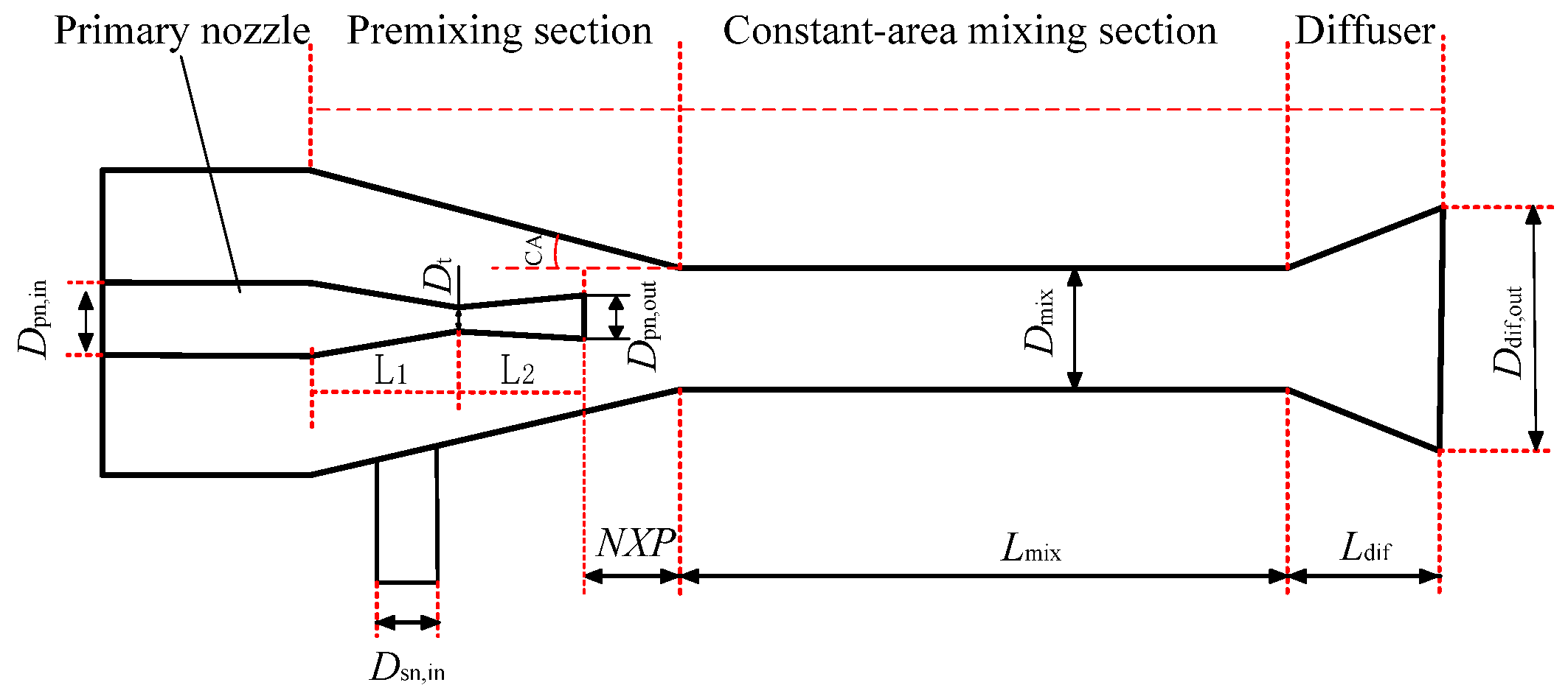
Figure 1. Structure diagram of two-phase ejector.
Processes 13 01933 g001
Figure 2. Ejector expansion refrigeration cycle: (a) schematic of cycle; (b) p-h diagram of cycle.
Processes 13 01933 g002
Figure 3. Grid structure of the ejector.
Processes 13 01933 g003
Figure 4. Comparison between the numerical data and experimental results: (a) absolute error; (b) relative error.
Processes 13 01933 g004
Figure 5. Distributions of pressure, velocity, and gas volume fraction along ejector centerline.
Processes 13 01933 g005
Figure 6. Influence of NXP on MER.
Processes 13 01933 g006
Figure 7. Velocity field visualization at different values of NXP.
Processes 13 01933 g007
Figure 8. Influence of CA on MER.
Processes 13 01933 g008
Figure 9. Velocity field visualization for different values of CA.
Processes 13 01933 g009
Figure 10. Flowline in the ejector (CA = 60°).
Processes 13 01933 g010
Figure 11. Influence of DDR on MER.
Processes 13 01933 g011
Figure 12. Velocity field visualization for different values of DDR.
Processes 13 01933 g012
Figure 13. Influence of LDR on MER.
Processes 13 01933 g013
Figure 14. Velocity field visualization for different values of LDR.
Processes 13 01933 g014
Table 1. Geometric parameters of baseline ejector.
ParameterSize (mm)
Dpn,in10
Dt0.7
Dpn,out1.5
Dmix5
Ddif,out9.4
Dsn,in6
Lpn,d6
Lmix50
Ldif50
Table 2. Boundary conditions of ejector.
Boundary LocationCondition Type
Primary inletPressure—inlet/2.13 MPa
Secondary inletPressure—inlet/0.75 MPa
Ejector exitPressure—outlet/0.85 MPa
All wallsAdiabatic, no slip
Table 3. Model validation errors in the literature.
ReferenceWorking FluidTurbulence ModelPrimary MFR
Relative Error
Secondary MFR Relative Error
Li and Deng [26]R744k-ε Realizable−34.55–25.71%−19.25–5.33%
Long et al. [32]R744k-ωN/A−10–22%
Bai et al. [43]R290k-ω SST−12–12%N/A
Bodys et al. [46]R744k-ε Standard
k-ε Realizable
k-ω Standard
k-kl-ω
5–30%25–35%
Li et al. [47]R744k-ε−6.48–14.8%−17.8–4.33%
N/A: No data in the original literature.
Table 4. Changes in MER with geometrical parameters.
NXP (mm)CA (°)DDRLDR
13151719203045605.05.76.47.18.910.011.112.4
MER0.620.710.770.640.390.680.660.660.580.660.700.620.690.690.760.58
Disclaimer/Publisher’s Note: The statements, opinions and data contained in all publications are solely those of the individual author(s) and contributor(s) and not of MDPI and/or the editor(s). MDPI and/or the editor(s) disclaim responsibility for any injury to people or property resulting from any ideas, methods, instructions or products referred to in the content.