
Review of Automotive Thermoelectric Generator Structure Design and Optimization for Performance Enhancement


 ,
,
Abstract
1. Introduction
2. Design and Optimization of TEM
2.1. Thermoelectric Materials
2.2. Geometric Structure of TEM
2.2.1. Segmented TEM
2.2.2. Non-Segmented TEM
2.2.3. Multi-Stage TEM
3. Structure Design and Optimization of HEX
3.1. External Structure
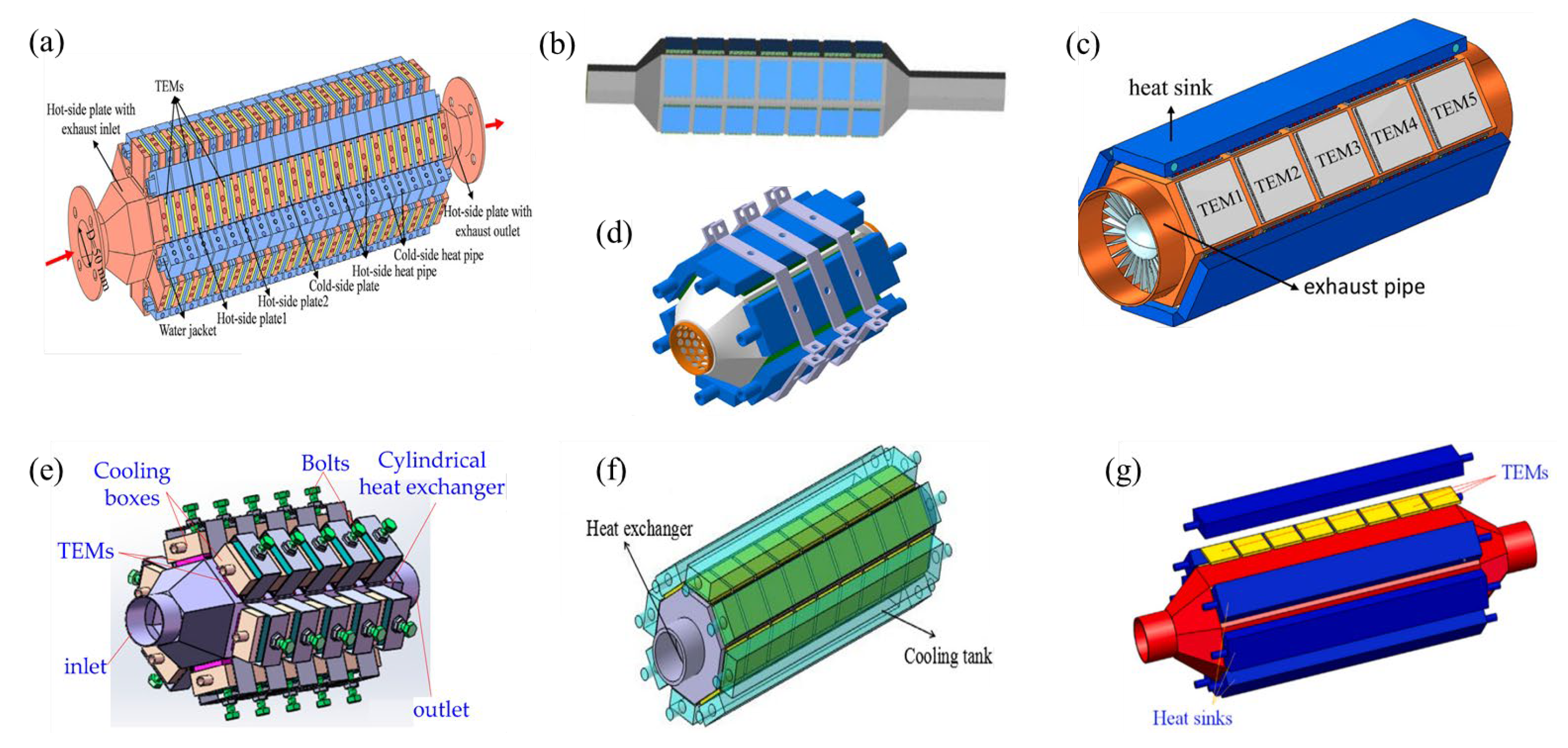
3.1.1. Plate HEX

3.1.2. Polygonal HEX
3.1.3. Annular HEX
3.2. Inner Structure
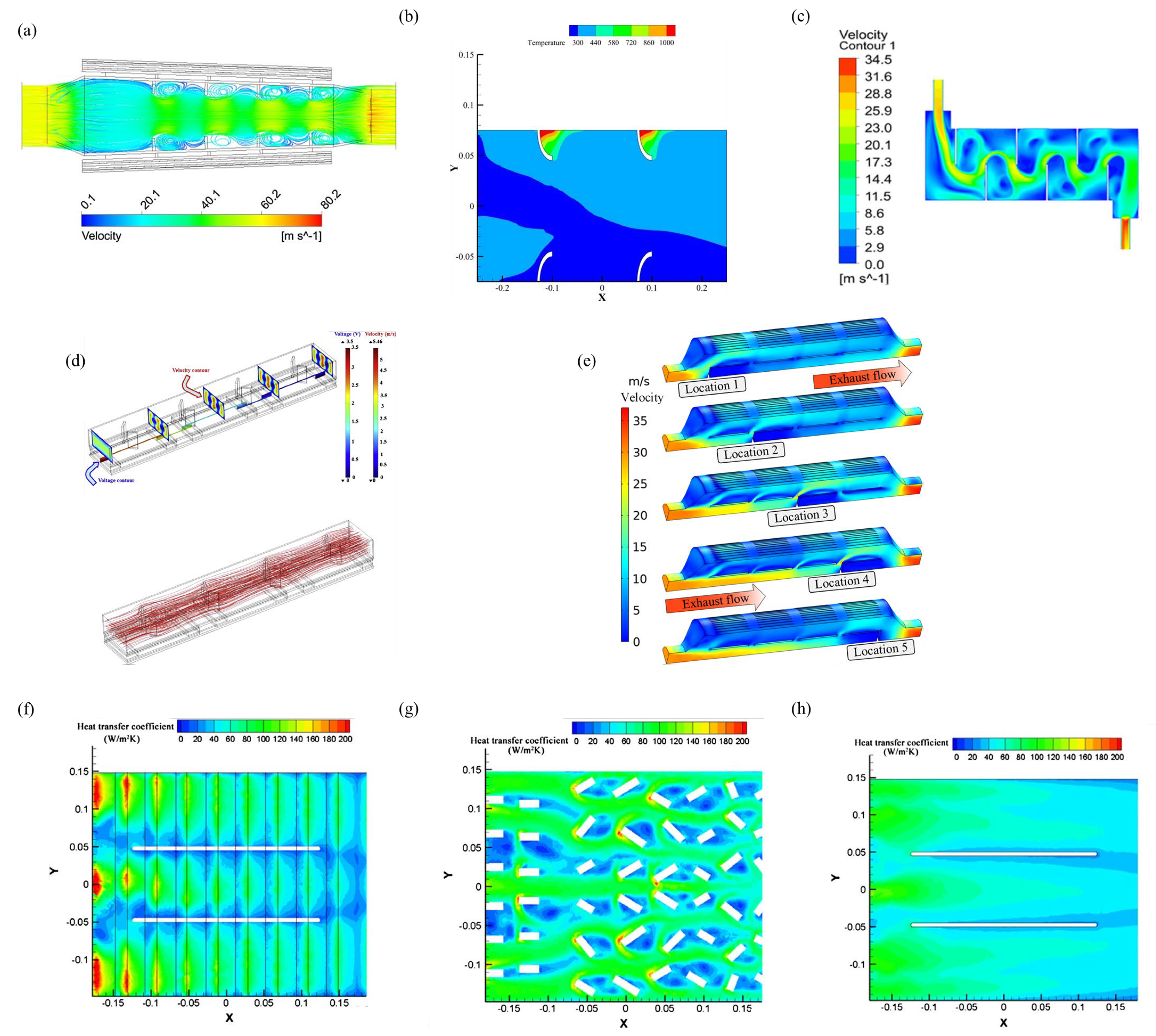
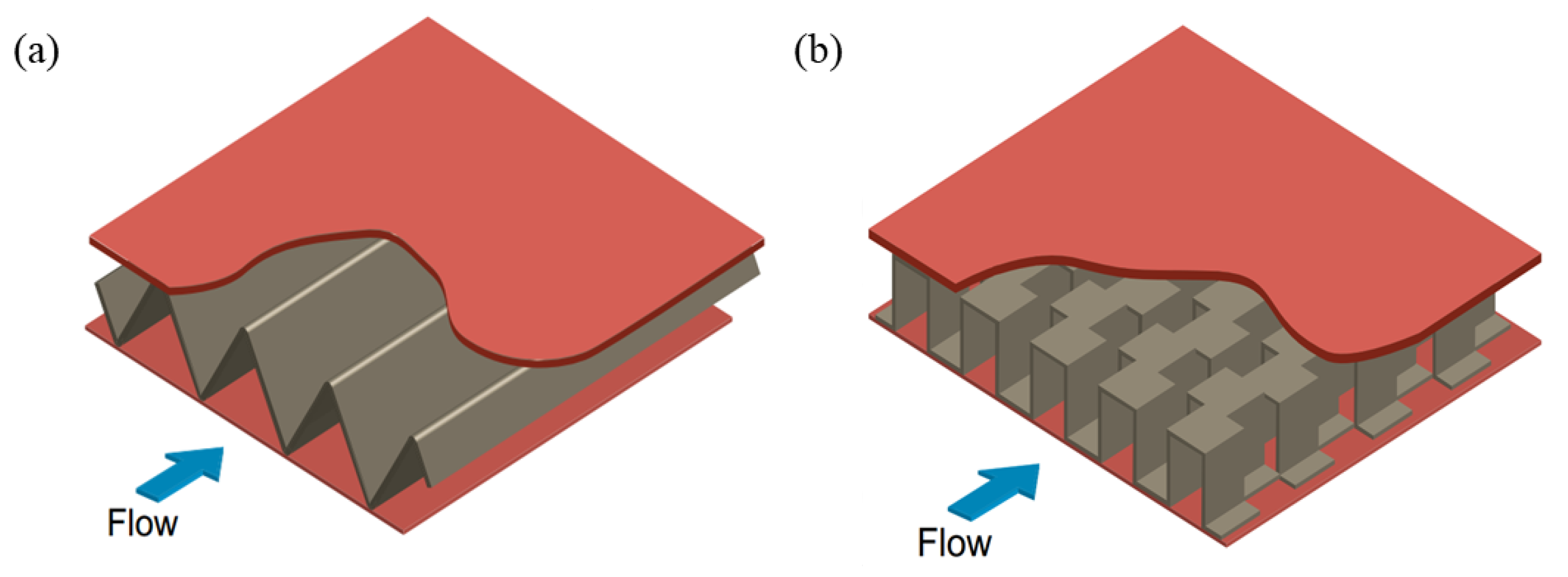
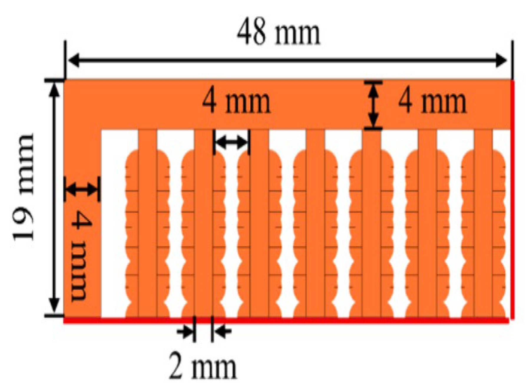
3.2.1. Fin
3.2.2. Dimple
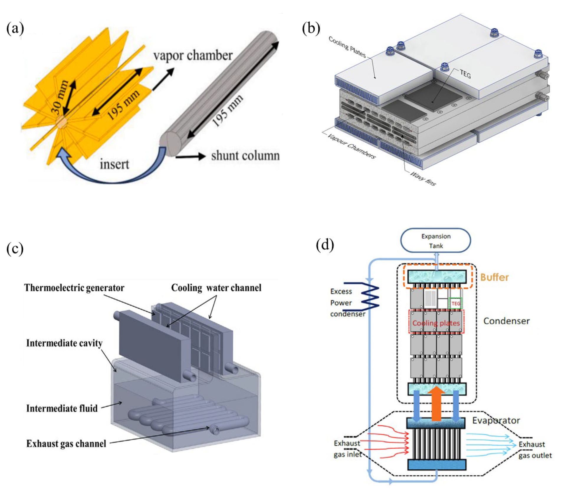
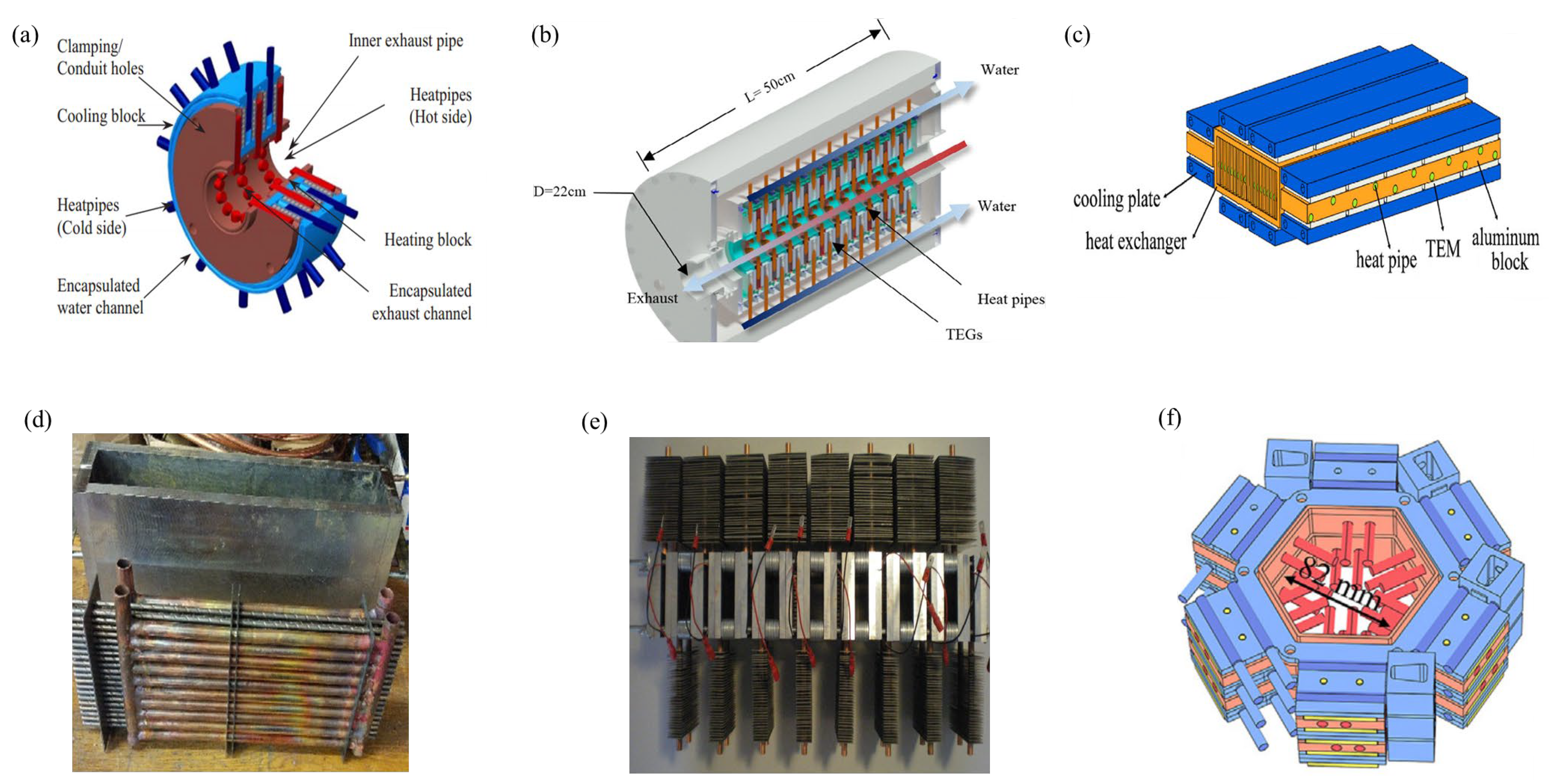
3.2.3. Heat Pipe
3.2.4. Intermediate Fluid
3.2.5. Baffle
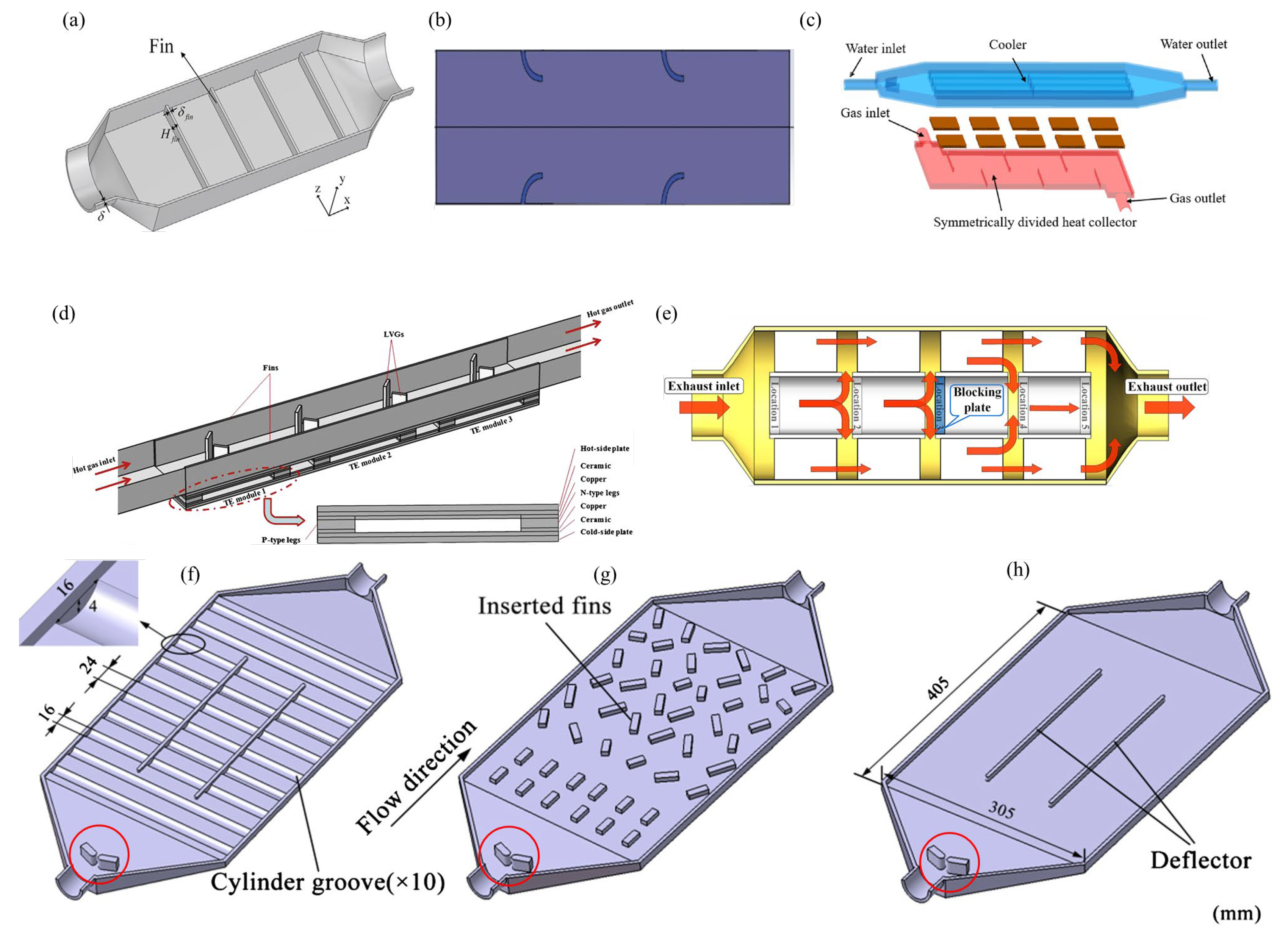
3.2.6. Metal Foam
3.2.7. PCM
4. Structure Design and Optimization of HSK
4.1. Coolant Selection
4.2. Flow Path Layout
4.3. Channel Geometry Refinements
5. Analysis and Optimization Methods
5.1. Theoretical Analysis

5.2. Numerical Simulation
5.3. Experimental Testing
5.4. Non-Algorithmic Hybrid Method
5.5. Algorithm-Based Hybrid Method
6. Future Prospects
7. Conclusions
- (1)
- Current TEG designs employ serial development, inadequately accounting for the coupling mechanisms among the TEM, HEX, and HSK. Future efforts should develop collaborative optimization to achieve dynamic multi-objective equilibrium between structural reliability and energy gains under multiphysics coupling.
- (2)
- Thermoelectric materials achieve ZT improvements via interface and nanostructure engineering. TEM designs include segmented and non-segmented configurations: segmented ones optimize material combinations, while non-segmented ones enhance thermal stress distribution. Multi-stage TEMs boost efficiency through series and parallel arrangements. Cuboid structures dominate manufacturability, whereas unconventional geometries excel in specific thermal conditions.
- (3)
- HEX designs prioritize external and internal configurations. Plate HEX features compactness and modularity, while polygonal design maximizes heat transfer areas for TEM integration. Annular configuration suits curved exhaust pipe but faces modularity constraints. Internally, the fin expands the surface and induces turbulence, the baffle optimizes localized flow, and metal foam balances efficiency and backpressure loss. Heat pipe enables phase-change heat transfer, synergizing with PCM to stabilize temperature through latent heat absorption.
- (4)
- The HSKs are classified as active, passive, or hybrid systems based on TEG requirements. Active HSKs utilize forced convection, with water cooling dominating automotive TEG, while hybrid system integrates heat pipe, fin, or combined cooling systems. Key optimizations include advanced coolant selection, flow channel redesign, and geometric modifications.
- (5)
- Optimization methods include theoretical analysis, numerical simulation, experimental testing, and hybrid approaches, requiring strategies to balance computational efficiency and accuracy based on system complexity and resource availability. The 2D/3D thermal resistance models, fluid–thermal–electric coupled model, and algorithm-based hybrid method better suit structural optimization.
- (6)
- While research on automotive TEG has achieved notable progress, the practical application remains predominantly confined to laboratory-scale demonstration. To realize commercial viability, there is an urgent need to establish systematic design standards adaptable to diverse vehicle platforms and develop universal optimization methodologies, thereby accelerating industrial-scale deployment.
Author Contributions
Funding
Data Availability Statement
Conflicts of Interest
Nomenclature
| Symbols | |||
| V | exhaust gas flow velocity | P | maximum output power |
| T | inlet temperature | Pnet | maximum net power |
| flow rate | η | conversion efficiency | |
| mass flow rate | ηnet | net conversion efficiency | |
| Abbreviations | |||
| TEG | thermoelectric generator | TWC | three-way catalyst |
| TEM | thermoelectric module | PPI | pores per inch |
| HEX | heat exchanger | PCM | phase-change material |
| HSK | heat sink | ||
References
- Bei, X.; Yu, X.; Li, D.; Sun, Q.; Yu, Y.; Wang, Y.; Okonkwo, C.E.; Zhou, C. Heat source replacement strategy using catalytic infrared: A future for energy saving drying of fruits and vegetables. J. Food Sci. 2023, 88, 4827–4839. [Google Scholar] [CrossRef] [PubMed]
- Zhu, Z.; Yang, Y.; Wang, D.; Cai, Y.; Lai, L. Energy Saving Performance of Agricultural Tractor Equipped with Mechanic-Electronic-Hydraulic Powertrain System. Agriculture 2022, 12, 436. [Google Scholar] [CrossRef]
- Zhu, Z.; Chai, X.; Xu, L.; Quan, L.; Yuan, C.; Tian, S. Design and performance of a distributed electric drive system for a series hybrid electric combine harvester. Biosyst. Eng. 2023, 236, 160–174. [Google Scholar] [CrossRef]
- Zhu, Z.; Zeng, L.; Chen, L.; Zou, R.; Cai, Y. Fuzzy Adaptive Energy Management Strategy for a Hybrid Agricultural Tractor Equipped with HMCVT. Agriculture 2022, 12, 1986. [Google Scholar] [CrossRef]
- Liu, J.; Xia, C.; Jiang, D.; Shang, G.; Han, J.; Sun, Y. Determination and Application of Maximum Efficiency Curve of Crawler Electric Tractor Motors. Math Probl. Eng. 2021, 2021, 1310926. [Google Scholar] [CrossRef]
- Luo, D.; Yu, Y.; Yan, Y.; Chen, W.; Cao, B. Increasing power densities in a thermoelectric generator by stacking and incorporating dual heat pipes. Device 2024, 2, 100435. [Google Scholar] [CrossRef]
- Liu, C.; Wang, Q.; Wang, Y.; Wang, Z.; Han, X.; Zhou, Q.; He, Z.; Yin, T. Automobile exhaust flexible thermoelectric harvester enabled by liquid metal-based heatsink. Energy Convers. Manag. 2024, 316, 118826. [Google Scholar] [CrossRef]
- Quan, R.; Zhou, Y.; Yao, S.; Wan, H.; Chang, Y. Improving the performance of a polygonal automobile exhaust thermoelectric generator with a crested porcupine optimizer. Appl. Therm. Eng. 2025, 268, 125946. [Google Scholar] [CrossRef]
- Quan, R.; Tang, X.; Quan, S.; Huang, L. A Novel Optimization Method for the Electric Topology of Thermoelectric Modules Used in an Automobile Exhaust Thermoelectric Generator. J. Electron. Mater. 2013, 42, 1469–1475. [Google Scholar] [CrossRef]
- Tang, X.; Zhang, K.; Tan, S.; Peng, X.; Long, M. Effect of quantum interference and doping on thermoelectric performance in GYNR and GYCNNR molecular junctions with PBCF-graphene nanoribbon electrodes. Chem. Phys. 2025, 591, 112585. [Google Scholar] [CrossRef]
- Nguyen, T.H.; Nguyen, V.Q.; Van Cuong, P.; Phan, N.N.; Park, J.H.; Park, S.; Cho, S. Enhancing the thermoelectric performance of Bi2Se3 single crystals via Sn doping. Solid State Commun. 2025, 397, 115849. [Google Scholar] [CrossRef]
- Ju, H.; Park, D.; Kim, M.; Kim, J. Copper telluride with manipulated carrier concentrations for high-performance solid-state thermoelectrics. J. Mater Sci. Technol. 2022, 129, 190–195. [Google Scholar] [CrossRef]
- Luo, D.; Zhang, H.; Cao, J.; Yan, Y.; Cao, B. Numerical investigation and optimization of a hexagonal thermoelectric generator with diverging fins for exhaust waste heat recovery. Energy 2024, 301, 131756. [Google Scholar] [CrossRef]
- Yan, S.; Moria, H.; Asaadi, S.; Sadighi Dizaji, H.; Khalilarya, S.; Jermsittiparsert, K. Performance and profit analysis of thermoelectric power generators mounted on channels with different cross-sectional shapes. Appl. Therm. Eng. 2020, 176, 115455. [Google Scholar] [CrossRef]
- Liu, J.; Xu, M.; Guo, W.; Xi, W.; Liu, C.; Sunden, B. Flow and heat transfer mechanism of a regenerative cooling channel mounted with pin-fins using supercritical CO2 as coolant. Int. J. Therm. Sci. 2025, 208, 109425. [Google Scholar] [CrossRef]
- Ni, P.; Hua, R.; Jiang, H.; Wang, X.; Zhang, X.; Li, X. Thermal flow and thermoelectricity characteristics in a sandwich flat plate thermoelectric power generation device under diesel engine exhaust conditions. Energy 2024, 308, 132815. [Google Scholar] [CrossRef]
- Luo, D.; Liu, Z.; Yan, Y.; Li, Y.; Wang, R.; Zhang, L.; Yang, X. Recent advances in modeling and simulation of thermoelectric power generation. Energy Convers. Manag. 2022, 273, 116389. [Google Scholar] [CrossRef]
- Bhakta, S.; Kundu, B. A Review of Thermoelectric Generators in Automobile Waste Heat Recovery Systems for Improving Energy Utilization. Energies 2024, 17, 1016. [Google Scholar] [CrossRef]
- Ochieng, A.O.; Megahed, T.F.; Ookawara, S.; Hassan, H. Comprehensive review in waste heat recovery in different thermal energy-consuming processes using thermoelectric generators for electrical power generation. Process. Saf. Environ. 2022, 162, 134–154. [Google Scholar] [CrossRef]
- Tohidi, F.; Ghazanfari Holagh, S.; Chitsaz, A. Thermoelectric Generators: A comprehensive review of characteristics and applications. Appl. Therm. Eng. 2022, 201, 117793. [Google Scholar] [CrossRef]
- Shittu, S.; Li, G.; Zhao, X.; Ma, X. Review of thermoelectric geometry and structure optimization for performance enhancement. Appl. Energy 2020, 268, 115075. [Google Scholar] [CrossRef]
- Shen, Z.; Tian, L.; Liu, X. Automotive exhaust thermoelectric generators: Current status, challenges and future prospects. Energy Convers. Manag. 2019, 195, 1138–1173. [Google Scholar] [CrossRef]
- Luo, D.; Li, Y.; Yan, Y.; Hu, X.; Fan, X.; Chen, W.; Ren, Y.; Cao, B. Realizing ultrahigh ZT value and efficiency of the Bi2Te3 thermoelectric module by periodic heating. Energy Convers. Manag. 2023, 296, 117669. [Google Scholar] [CrossRef]
- Zhao, K.; Liu, C.; Shao, T.; Fan, Y.; Chen, R.; Pan, X. Enhanced thermoelectric performance of Bi2Te3 by carbon nanotubes and silicate aerogel co-doping toward ocean energy harvesting. Mater. Today Sustain. 2023, 23, 100476. [Google Scholar] [CrossRef]
- Lv, M.; Wu, N.; Fan, X.; Zheng, W.; Singh, D.J. Bi2X (X = Ge, Sn) monolayers: Promising thermoelectric materials with ultra-low thermal conductivity. Mater. Today Phys. 2024, 49, 101594. [Google Scholar] [CrossRef]
- Ding, Y.; Liang, X.; Luo, L.; Hu, W.; Long, Y.; Song, Y.; Kang, K. Effect of lattice defects on electronic structure and thermoelectric properties of two- dimensional WS2 materials. Mater. Today Commun. 2023, 37, 107449. [Google Scholar] [CrossRef]
- Priyambada, A.; Mohanty, A.; Parida, P. Effect of vacancies on structural, electronic, elastic, and thermoelectric properties of CdIn2Se4 defect chalcopyrite-type semiconductor: An ab-initio approach. Mater. Today Commun. 2023, 37, 107338. [Google Scholar] [CrossRef]
- Aaouita, K.E.; Mediane, N.; Goumrhar, F.; Drissi, L.B.; Laamara, R.A. Enhanced spintronic and thermoelectric performance in vanadium-doped CaTiO3: An ab-initio study. Comput. Condens. Matter 2025, 42, e00999. [Google Scholar] [CrossRef]
- Qiu, W.; He, H.; Wang, Z.; Hu, Q.; Cui, X.; Wang, Z.; Zhang, Y.; Gu, L.; Yang, L.; Sun, Y.; et al. Enhancing the figure of merit of n-type PbTe materials through multi-scale graphene induced interfacial engineering. Nano Today 2021, 39, 101176. [Google Scholar] [CrossRef]
- Wei, J.; Lv, E.; Shi, Z.; Jiang, Z.; Sheng, L.; Gao, W.; Li, X.; Liu, Y. Enhancing the thermoelectric characteristics of thermoelectric cement matrix composites by (Ca0.87Ag0.1La0.03)3Co4O9 binary metal oxide. Ceram. Int. 2023, 49, 37829–37836. [Google Scholar] [CrossRef]
- Amirkhizi, P.; Madre, M.A.; Dura, O.J.; Torres, M.A.; Sotelo, A.; Kovalevsky, A.V.; Rasekh, S. Enhancing thermoelectric performance of CaMnO3 through a Y- and La- dual-doping strategy. Ceram. Int. 2025, 51, 9421–9428. [Google Scholar] [CrossRef]
- Wang, Y.; Wei, J.; Miao, Z.; Zhou, Y.; Guo, Y.; Li, X.; Zhang, H. Excellent thermoelectric properties of P-type cement-based composites through a universal defect engineering approach for large-scale energy harvesting. Constr. Build. Mater. 2022, 351, 128967. [Google Scholar] [CrossRef]
- Benkaddour, I.; Haddou, A.; Khachai, Y.A.; Baki, N.; Chiker, F.; Khachai, H.; Khenata, R.; Metadjer, N.; Bin-Omran, S.; Shankar, A.; et al. Exploring optoelectronic, optical thin films, mechanical and thermal transport properties of bromide double perovskites Rb2Ag(Ga/In)Br6 for photovoltaic and thermoelectric applications. Mat. Sci. Semicon. Proc. 2025, 185, 108974. [Google Scholar] [CrossRef]
- Irfan, M.; Ibrahim, F.A.; Hamdy, M.S.; Issa, S.A.M.; Zakaly, H.M.H. First principles investigations of linear and nonlinear optical, radiation shielding and thermoelectric properties of the non-centrosymmetric Ba-based chalcogenides Ba2In2X5 (X = S, Te). Mat. Sci. Semicon. Proc. 2025, 185, 108957. [Google Scholar] [CrossRef]
- Mehmood, S.; Ali, Z.; Altuijri, R.; Abu El Maati, L.; Khan, S.R.; Trukhanov, S.V.; Zubar, T.I.; Sayyed, M.I.; Tishkevich, D.I.; Trukhanov, A.V. First-principles study of the rare earth anti-TH3P4 type zintles for opto-electronic and thermoelectric applications. Phys. B Condensed. Matter 2023, 670, 415353. [Google Scholar] [CrossRef]
- Zhang, Y.; Yang, C.; Lu, R.; Zhang, S.; Tang, B. Flexible thermoelectric device with excellent durability towards self-powered light intensity detection. Compos. Sci. Technol. 2022, 227, 109616. [Google Scholar] [CrossRef]
- Tang, D.; Dan, M.; Zhang, Y. High performance piezotronic thermoelectric devices based on zigzag MoS2 nanoribbon. Nano Energy 2022, 104, 107888. [Google Scholar] [CrossRef]
- Xiang, J.; Dai, B.; Zhang, X.; Guo, H.; Cheng, W.; Ge, N. High thermoelectric performance of intrinsic few-layers T-HfSe2. Mater. Today Commun. 2022, 33, 104789. [Google Scholar] [CrossRef]
- Wehbe, M.; Dgheim, J.; Sassine, E. House electrical generation using thermoelectric cinder block: Case study on Lebanese hollow block. Sustain. Energy Techn. 2022, 50, 101815. [Google Scholar] [CrossRef]
- Dudnikov, V.A.; Orlov, Y.S.; Vereshchagin, S.N.; Belov, A.A.; Solovyov, L.A.; Borus, A.A.; Zharkov, S.M.; Zeer, G.M.; Ustyuzhanin, Y.N.; Volochaev, M.N.; et al. Improving of thermoelectric figure of merit in Sr0.925Dy0.075 TiO3 ceramics. Ceram. Int. 2024, 50, 55026–55033. [Google Scholar] [CrossRef]
- Wu, T.; Shi, X.; Deng, Y.; Liu, Y.; Zhu, M.; Liu, W.; Li, M.; Yue, F.; Huang, P.; Chen, Z.; et al. Incorporating graphene quantum dots boosts thermoelectric performance of PEDOT:PSS films. Chem. Eng. J. 2025, 506, 160219. [Google Scholar] [CrossRef]
- Aldaghfag, S.A.; Aziz, A.; Younas, A.; Yaseen, M.; Murtaza, A.; Hegazy, H.H. Investigation of electronic, optical and thermoelectric features of X2ScAgCl6 (X=K, Na) double perovskites for renewable energy applications. J. Solid State Chem. 2022, 312, 123179. [Google Scholar] [CrossRef]
- Hamid, M.; Faizan, M.; Alrebdi, T.A.; Shaheen, K.; Khan, S.H. Computational study of the lattice type, band structure, and thermoelectric properties of LiSbX2 (X = S, Se, Te). Chem. Phys. 2025, 591, 112600. [Google Scholar] [CrossRef]
- Pham, A.T.T.; Le, O.K.T.; Phan, T.T.T.; Hoang, D.V.; Nguyen, T.H.; Le, N.D.; Phan, T.B.; Tran, V.C. Enhancing transparent thermoelectric properties of Sb-doped ZnO thin films via controlled deposition temperature. Vacuum 2022, 202, 111137. [Google Scholar] [CrossRef]
- Darhi, Z.; Rawat, A.; Pandey, R.; Elfarh, L. First-principles study of thermoelectric properties of the bulk and Sb-doped orthorhombic ZnAs and CdAs. Mat. Sci. Semicon. Proc. 2025, 185, 108896. [Google Scholar] [CrossRef]
- Poon, S.J. Half Heusler compounds: Promising materials for mid-to-high temperature thermoelectric conversion. J. Phys. D Appl. Phys. 2019, 49, 493001. [Google Scholar] [CrossRef]
- Azam, K.; Akhtar, S.; Gong, Y.Y.; Routledge, M.N.; Ismail, A.; Oliveira, C.A.F.; Iqbal, S.Z.; Ali, H. Evaluation of the impact of activated carbon-based filtration system on the concentration of aflatoxins and selected heavy metals in roasted coffee. Food Control. 2021, 121, 107583. [Google Scholar] [CrossRef]
- Yuan, J.; Zhu, Y.; Wang, J.; Gan, L.; He, M.; Zhang, T.; Li, P.; Qiu, F. Preparation and application of Mg–Al composite oxide/coconut shell carbon fiber for effective removal of phosphorus from domestic sewage. Food Bioprod. Process. 2021, 126, 293–304. [Google Scholar] [CrossRef]
- Wang, X.; Xu, Y.; Li, Y.; Li, Y.; Li, Z.; Zhang, W.; Zou, X.; Shi, J.; Huang, X.; Liu, C.; et al. Rapid detection of cadmium ions in meat by a multi-walled carbon nanotubes enhanced metal-organic framework modified electrochemical sensor. Food Chem. 2021, 357, 129762. [Google Scholar] [CrossRef]
- Li, W.; Hu, X.; Li, Q.; Shi, Y.; Zhai, X.; Xu, Y.; Li, Z.; Huang, X.; Wang, X.; Shi, J.; et al. Copper nanoclusters @ nitrogen-doped carbon quantum dots-based ratiometric fluorescence probe for lead (II) ions detection in porphyra. Food Chem. 2020, 320, 126623. [Google Scholar] [CrossRef]
- Liang, N.; Hu, X.; Li, W.; Mwakosya, A.W.; Guo, Z.; Xu, Y.; Huang, X.; Li, Z.; Zhang, X.; Zou, X.; et al. Fluorescence and colorimetric dual-mode sensor for visual detection of malathion in cabbage based on carbon quantum dots and gold nanoparticles. Food Chem. 2021, 343, 128494. [Google Scholar] [CrossRef]
- He, X.; Gu, J.; Hao, Y.; Zheng, M.; Wang, L.; Yu, J.; Qin, X. Continuous manufacture of stretchable and integratable thermoelectric nanofiber yarn for human body energy harvesting and self-powered motion detection. Chem. Eng. J. 2022, 450, 137937. [Google Scholar] [CrossRef]
- Fan, X.; Zhang, X.; Zhang, X.; Shiu, B.; Lin, J.; Lou, C.; Li, T. Energy filtering effect of flexible organic/inorganic nanocomposite thermoelectric fabrics to harvest human heat and solar energy. Polymer 2023, 283, 126224. [Google Scholar] [CrossRef]
- Cao, J.; Tan, X.Y.; Jia, N.; Zheng, J.; Chien, S.W.; Ng, H.K.; Tan, C.K.I.; Liu, H.; Zhu, Q.; Wang, S.; et al. Designing good compatibility factor in segmented Bi0.5Sb1.5Te3—GeTe thermoelectrics for high power conversion efficiency. Nano Energy 2022, 96, 107147. [Google Scholar] [CrossRef]
- Li, J.; Sun, Y.; Shi, W.; Li, Y.; Zou, Y.; Zhang, H. Fabrication, characterization, and in vitro digestion of gelatin/gluten oleogels from thermally crosslinked electrospun short fiber aerogel templates. Food Chem. 2024, 454, 139804. [Google Scholar] [CrossRef]
- Ren, M.; Fakayode, O.A.; Kong, F.; Zhou, C.; Chen, L.; Fan, X.; Liang, J.; Li, H. Characterization of cellulose nanocrystals prepared by different delignification methods and application of ultra-light, hydrophobic aerogels as oil absorbent in food systems. Ind. Crop. Prod. 2023, 197, 116653. [Google Scholar] [CrossRef]
- Chen, Y.; Chen, H.; Dai, Y.; Xiao, J.; Qiu, F.; Zhang, T. Honeycomb porous regenerated cellulose aerogel films with enhanced thermal dissipation for agricultural mulch application. Food Bioprod. Process. 2024, 147, 418–427. [Google Scholar] [CrossRef]
- Jing, Z.; Ding, J.; Zhang, T.; Yang, D.; Qiu, F.; Chen, Q.; Xu, J. Flexible, versatility and superhydrophobic biomass carbon aerogels derived from corn bracts for efficient oil/water separation. Food Bioprod. Process. 2019, 115, 134–142. [Google Scholar] [CrossRef]
- Maksymuk, M.; Dzundza, B.; Matkivsky, O.; Horichok, I.; Shneck, R.; Dashevsky, Z. Development of the high performance thermoelectric unicouple based on Bi2Te3 compounds. J. Power Sources 2022, 530, 231301. [Google Scholar] [CrossRef]
- Alghamdi, N.; El-Shamy, A.G. A review on the recent progress in thermoelectric aerogels: Fabrications, generators, marine harvesting, sensors, and thermocells applications. Synth. Met. 2025, 310, 117776. [Google Scholar] [CrossRef]
- Cui, X.; Chen, X.; Gao, Z. Research on the power generation performance and optimization of thermoelectric generators for recycling remaining cold energy. Energy 2024, 299, 131422. [Google Scholar] [CrossRef]
- Ge, M.; Zhao, Y.; Li, Y.; He, W.; Xie, L.; Zhao, Y. Structural optimization of thermoelectric modules in a concentration photovoltaic–thermoelectric hybrid system. Energy 2022, 244, 123202. [Google Scholar] [CrossRef]
- Yilbas, B.S.; Sahin, A.Z. Thermoelectric device and optimum external load parameter and slenderness ratio. Energy 2010, 35, 5380–5384. [Google Scholar] [CrossRef]
- Fan, L.; Zhang, G.; Wang, R.; Jiao, K. A comprehensive and time-efficient model for determination of thermoelectric generator length and cross-section area. Energy Convers. Manag. 2016, 122, 85–94. [Google Scholar] [CrossRef]
- Harish, S.; Sivaprahasam, D.; Jayachandran, B.; Gopalan, R.; Sundararajan, G. Performance of bismuth telluride modules under thermal cycling in an automotive exhaust thermoelectric generator. Energy Convers. Manag. 2021, 232, 113900. [Google Scholar] [CrossRef]
- Kim, H.S.; Kikuchi, K.; Itoh, T.; Iida, T.; Taya, M. Design of segmented thermoelectric generator based on cost-effective and light-weight thermoelectric alloys. Mater. Sci. Eng. B 2014, 185, 45–52. [Google Scholar] [CrossRef]
- Shittu, S.; Li, G.; Zhao, X.; Ma, X.; Akhlaghi, Y.G.; Ayodele, E. High performance and thermal stress analysis of a segmented annular thermoelectric generator. Energy Convers. Manag. 2019, 184, 180–193. [Google Scholar] [CrossRef]
- He, H.; Xie, Y.; Zuo, Q.; Chen, W.; Shen, Z.; Ma, Y.; Zhang, H.; Zhu, G.; Ouyang, Y. Optimization analysis for thermoelectric performance improvement of biconical segmented annular thermoelectric generator. Energy 2024, 306, 132397. [Google Scholar] [CrossRef]
- Erturun, U.; Erermis, K.; Mossi, K. Effect of various leg geometries on thermo-mechanical and power generation performance of thermoelectric devices. Appl. Therm. Eng. 2014, 73, 128–141. [Google Scholar] [CrossRef]
- Zhang, Y.; Guo, K.; Wang, C.; Zhang, J.; Wang, Y.; Xi, T.; Su, G.H.; Qiu, S. Artificial neural network for geometric design and optimization of three-stage segmented thermoelectric generators. Appl. Therm. Eng. 2024, 256, 124077. [Google Scholar] [CrossRef]
- Wu, Y.; Yang, J.; Chen, S.; Zuo, L. Thermo-element geometry optimization for high thermoelectric efficiency. Energy 2018, 147, 672–680. [Google Scholar] [CrossRef]
- Oki, S.; Natsui, S.; Suzuki, R.O. Performance Analysis of Thermoelectric Modules Consisting of Square Truncated Pyramid Elements Under Constant Heat Flux. J. Electron. Mater. 2018, 47, 3288–3297. [Google Scholar] [CrossRef]
- Luo, D.; Liu, Z.; Cao, J.; Yan, Y.; Cao, B. Performance investigation and optimization of an L-type thermoelectric generator. Energy 2024, 307, 132768. [Google Scholar] [CrossRef]
- Wang, R.; Meng, Z.; Luo, D.; Yu, W.; Zhou, W. A Comprehensive Study on X-Type Thermoelectric Generator Modules. J. Electron. Mater. 2020, 49, 4343–4354. [Google Scholar] [CrossRef]
- Ibeagwu, O.I. Modelling and comprehensive analysis of TEGs with diverse variable leg geometry. Energy 2019, 180, 90–106. [Google Scholar] [CrossRef]
- Luo, D.; Zhang, H.; Cao, J.; Yan, Y.; Cao, B. Innovative design of an annular thermoelectric generator for enhanced automotive waste heat recovery. Energy Convers. Manag. 2024, 313, 118584. [Google Scholar] [CrossRef]
- Zhou, X.; M Abed, A.; Chaturvedi, R.; Abdullaeva, B.S.; Shawabkeh, A.; Fouad, Y.; Riaz, F. A novel thermal management system for a cylindrical battery based on tubular thermoelectric generator. Case Stud. Therm. Eng. 2024, 59, 104585. [Google Scholar] [CrossRef]
- Luo, D.; Liu, Z.; Cao, J.; Yan, Y. Feasibility and parametric study of a groove-type thermoelectric generator under multiphysics field conditions. Appl. Therm. Eng. 2025, 259, 124972. [Google Scholar] [CrossRef]
- Liu, K.; Tang, X.; Liu, Y.; Xu, Z.; Yuan, Z.; Li, J.; Zhang, Z. Preparation and optimization of miniaturized radioisotope thermoelectric generator based on concentric filament architecture. J. Power Sources 2018, 407, 14–22. [Google Scholar] [CrossRef]
- Niu, Z.; Yu, S.; Diao, H.; Li, Q.; Jiao, K.; Du, Q.; Tian, H.; Shu, G. Elucidating modeling aspects of thermoelectric generator. Int. J. Heat Mass Tran. 2015, 85, 12–32. [Google Scholar] [CrossRef]
- Shi, Y.; Mei, D.; Yao, Z.; Wang, Y.; Liu, H.; Chen, Z. Nominal power density analysis of thermoelectric pins with non-constant cross sections. Energy Convers. Manag. 2015, 97, 1–6. [Google Scholar] [CrossRef]
- Bian, M.; Xu, Z.; Tang, X.; Chen, C.; Jia, H. Tri-objective and multi-parameter geometric optimization of two-stage radioisotope thermoelectric generator based on NSGA-II. Appl. Therm. Eng. 2025, 258, 124685. [Google Scholar] [CrossRef]
- Long, Y.; Yin, E.; Li, Q.; Yang, S. Experimental study on a solar thermoelectric power generation system under non-uniform irradiation. Appl. Therm. Eng. 2024, 256, 124101. [Google Scholar] [CrossRef]
- Liang, X.; Sun, X.; Tian, H.; Shu, G.; Wang, Y.; Wang, X. Comparison and parameter optimization of a two-stage thermoelectric generator using high temperature exhaust of internal combustion engine. Appl. Energy 2014, 130, 190–199. [Google Scholar] [CrossRef]
- Zhang, H.; Xu, H.; Chen, B.; Dong, F.; Ni, M. Two-stage thermoelectric generators for waste heat recovery from solid oxide fuel cells. Energy 2017, 132, 280–288. [Google Scholar] [CrossRef]
- Zhai, X.; Sun, Y.; Cen, S.; Wang, X.; Zhang, J.; Yang, Z.; Li, Y.; Wang, X.; Zhou, C.; Arslan, M.; et al. Anthocyanins-encapsulated 3D-printable bigels: A colorimetric and leaching-resistant volatile amines sensor for intelligent food packaging. Food Hydrocoll. 2022, 133, 107989. [Google Scholar] [CrossRef]
- Guo, Z.; Li, Z.; Cen, S.; Liang, N.; Shi, J.; Huang, X.; Zou, X. Preparation of Pangasius hypophthalmus protein-stabilized pickering emulsions and 3D printing application. J. Food Eng. 2023, 341, 111333. [Google Scholar] [CrossRef]
- Hu, L.; Ding, F.; Liu, W.; Cheng, Y.; Zhu, J.; Ma, L.; Zhang, Y.; Wang, H. Effect of enzymatic-ultrasonic hydrolyzed chitooligosaccharide on rheology of gelatin incorporated yogurt and 3D printing. Food Hydrocoll. 2022, 132, 107851. [Google Scholar] [CrossRef]
- Ji, D.; Hu, S.; Feng, Y.; Qin, J.; Yin, Z.; Romagnoli, A.; Zhao, J.; Qian, H. Geometry optimization of solar thermoelectric generator under different operating conditions via Taguchi method. Energy Convers. Manag. 2021, 238, 114158. [Google Scholar] [CrossRef]
- Chen, J.; Wang, R.; Ding, R.; Luo, D. Matching design and numerical optimization of automotive thermoelectric generator system applied to range-extended electric vehicle. Appl. Energy 2024, 370, 123637. [Google Scholar] [CrossRef]
- Luo, D.; Wu, Z.; Yan, Y.; Ji, D.; Cheng, Z.; Wang, R.; Li, Y.; Yang, X. Optimal design of a heat exchanger for automotive thermoelectric generator systems applied to a passenger car. Appl. Therm. Eng. 2023, 227, 120360. [Google Scholar] [CrossRef]
- Chen, J.; Wang, R.; Ding, R.; Luo, D. Numerical study of a novel automotive thermoelectric generator system equipped with segmented converging heat exchanger. Case Stud. Therm. Eng. 2024, 57, 104367. [Google Scholar] [CrossRef]
- Luo, D.; Yang, S.; Yan, Y.; Cao, J.; Cao, B. Performance improvement of the automotive thermoelectric generator by extending the hot side area of the heat exchanger through heat pipes. Energy Convers. Manag. 2024, 310, 118472. [Google Scholar] [CrossRef]
- Wang, T.; Luan, W.; Liu, T.; Tu, S.; Yan, J. Performance enhancement of thermoelectric waste heat recovery system by using metal foam inserts. Energy Convers. Manag. 2016, 124, 13–19. [Google Scholar] [CrossRef]
- Luo, D.; Wang, R.; Yan, Y.; Sun, Z.; Zhou, W.; Ding, R. Comparison of different fluid-thermal-electric multiphysics modeling approaches for thermoelectric generator systems. Renew. Energy 2021, 180, 1266–1277. [Google Scholar] [CrossRef]
- Ge, M.; Li, Z.; Zhao, Y.; Xuan, Z.; Li, Y.; Zhao, Y. Experimental study of thermoelectric generator with different numbers of modules for waste heat recovery. Appl. Energy 2022, 322, 119523. [Google Scholar] [CrossRef]
- Zhao, Y.; Lu, M.; Li, Y.; Wang, Y.; Ge, M. Numerical investigation of an exhaust thermoelectric generator with a perforated plate. Energy 2023, 263, 125776. [Google Scholar] [CrossRef]
- Lan, S.; Yang, Z.; Chen, R.; Stobart, R. A dynamic model for thermoelectric generator applied to vehicle waste heat recovery. Appl. Energy 2018, 210, 327–338. [Google Scholar] [CrossRef]
- Risseh, A.E.; Nee, H.; Goupil, C. Electrical Power Conditioning System for Thermoelectric Waste Heat Recovery in Commercial Vehicles. IEEE Trans. Transp. Electrif. 2018, 4, 548–562. [Google Scholar] [CrossRef]
- Lan, S.; Stobart, R.; Chen, R. Performance comparison of a thermoelectric generator applied in conventional vehicles and extended-range electric vehicles. Energy Convers. Manag. 2022, 266, 115791. [Google Scholar] [CrossRef]
- Massaguer, A.; Massaguer, E.; Comamala, M.; Pujol, T.; Montoro, L.; Cardenas, M.D.; Carbonell, D.; Bueno, A.J. Transient behavior under a normalized driving cycle of an automotive thermoelectric generator. Appl. Energy 2017, 206, 1282–1296. [Google Scholar] [CrossRef]
- Wojciechowski, K.T.; Schmidt, M.; Zybala, R.; Merkisz, J.; Fuć, P.; Lijewski, P. Comparison of Waste Heat Recovery from the Exhaust of a Spark Ignition and a Diesel Engine. J. Electron. Mater. 2010, 39, 2034–2038. [Google Scholar] [CrossRef]
- Frobenius, F.; Gaiser, G.; Rusche, U.; Weller, B. Thermoelectric Generators for the Integration into Automotive Exhaust Systems for Passenger Cars and Commercial Vehicles. J. Electron. Mater. 2016, 45, 1433–1440. [Google Scholar] [CrossRef]
- Lu, X.; Yu, X.; Qu, Z.; Wang, Q.; Ma, T. Experimental investigation on thermoelectric generator with non-uniform hot-side heat exchanger for waste heat recovery. Energy Convers. Manag. 2017, 150, 403–414. [Google Scholar] [CrossRef]
- Wang, X.; Li, B.; Yan, Y.; Liu, S.; Li, J. A study on heat transfer enhancement in the radial direction of gas flow for thermoelectric power generation. Appl. Therm. Eng. 2016, 102, 176–183. [Google Scholar] [CrossRef]
- Zhang, Y.; Cleary, M.; Wang, X.; Kempf, N.; Schoensee, L.; Yang, J.; Joshi, G.; Meda, L. High-temperature and high-power-density nanostructured thermoelectric generator for automotive waste heat recovery. Energy Convers. Manag. 2015, 105, 946–950. [Google Scholar] [CrossRef]
- Fernández-Yañez, P.; Armas, O.; Capetillo, A.; Martínez-Martínez, S. Thermal analysis of a thermoelectric generator for light-duty diesel engines. Appl. Energy 2018, 226, 690–702. [Google Scholar] [CrossRef]
- Luo, D.; Wang, R.; Yu, W.; Zhou, W. A numerical study on the performance of a converging thermoelectric generator system used for waste heat recovery. Appl. Energy 2020, 270, 115181. [Google Scholar] [CrossRef]
- Akal, D.; Umut, I. Monitoring of electricity generation from exhaust waste heat and wireless data recording from a mobile phone in real driving conditions of a vehicle. Environ. Sci. Pollut. Res. 2023, 30, 100576–100583. [Google Scholar] [CrossRef]
- Fanciulli, C.; Abedi, H.; Nespoli, A.; Dondè, R.; La Terra, C.; Migliorini, F.; Passaretti, F.; De Iuliis, S. Additive fabrication and experimental validation of a lightweight thermoelectric generator. Sci. Rep. 2023, 13, 10042. [Google Scholar] [CrossRef]
- Weng, C.; Huang, M. A simulation study of automotive waste heat recovery using a thermoelectric power generator. Int. J. Therm. Sci. 2013, 71, 302–309. [Google Scholar] [CrossRef]
- Kim, T.Y.; Kwak, J.; Kim, B. Energy harvesting performance of hexagonal shaped thermoelectric generator for passenger vehicle applications: An experimental approach. Energy Convers. Manag. 2018, 160, 14–21. [Google Scholar] [CrossRef]
- Yang, H.; Shu, G.; Tian, H.; Ma, X.; Chen, T.; Liu, P. Optimization of thermoelectric generator (TEG) integrated with three-way catalytic converter (TWC) for harvesting engine’s exhaust waste heat. Appl. Therm. Eng. 2018, 144, 628–638. [Google Scholar] [CrossRef]
- Bai, W.; Yuan, X.; Liu, X. Numerical investigation on the performances of automotive thermoelectric generator employing metal foam. Appl. Therm. Eng. 2017, 124, 178–184. [Google Scholar] [CrossRef]
- Quan, R.; Li, T.; Yue, Y.; Chang, Y.; Tan, B. Experimental Study on a Thermoelectric Generator for Industrial Waste Heat Recovery Based on a Hexagonal Heat Exchanger. Energies 2020, 13, 3137. [Google Scholar] [CrossRef]
- Crane, D.; LaGrandeur, J.; Jovovic, V.; Ranalli, M.; Adldinger, M.; Poliquin, E.; Dean, J.; Kossakovski, D.; Mazar, B.; Maranville, C. TEG On-Vehicle Performance and Model Validation and What It Means for Further TEG Development. J. Electron. Mater. 2013, 42, 1582–1591. [Google Scholar] [CrossRef]
- Chen, J.; Wang, R.; Ding, R.; Liu, W.; Jiang, Y.; Luo, D. Innovative design and numerical optimization of a cylindrical thermoelectric generator for vehicle waste heat recovery. Energy Convers. Manag. 2025, 326, 119478. [Google Scholar] [CrossRef]
- Li, X.; Chen, L.; Yu, Z.; He, L.; Lee, J. Performance test and prediction on a radial π-type annular thermoelectric generator directly exposed to an automotive pipe for waste heat recovery. Appl. Therm. Eng. 2024, 251, 123621. [Google Scholar] [CrossRef]
- Luo, D.; Li, Z.; Yan, Y.; Cao, J.; Zhang, H.; Cao, B. Performance analysis and optimization of an annular thermoelectric generator integrated with vapor chambers. Energy 2024, 307, 132565. [Google Scholar] [CrossRef]
- Li, B.; Huang, K.; Yan, Y.; Li, Y.; Twaha, S.; Zhu, J. Heat transfer enhancement of a modularised thermoelectric power generator for passenger vehicles. Appl. Energy 2017, 205, 868–879. [Google Scholar] [CrossRef]
- Yang, W.; Jin, C.; Zhu, W.; Li, Y.; Zhang, R.; Huang, L.; Xie, C.; Shi, Y. Taguchi optimization and thermoelectrical analysis of a pin fin annular thermoelectric generator for automotive waste heat recovery. Renew. Energy 2024, 220, 119628. [Google Scholar] [CrossRef]
- Shen, Z.; Huang, B.; Liu, X. Effect of structure parameters on the performance of an annular thermoelectric generator for automobile exhaust heat recovery. Energy Convers. Manag. 2022, 256, 115381. [Google Scholar] [CrossRef]
- Yang, W.; Zhu, W.; Li, Y.; Zhang, L.; Zhao, B.; Xie, C.; Yan, Y.; Huang, L. Annular thermoelectric generator performance optimization analysis based on concentric annular heat exchanger. Energy 2022, 239, 122127. [Google Scholar] [CrossRef]
- Yang, W.; Zhu, W.; Du, B.; Wang, H.; Xu, L.; Xie, C.; Shi, Y. Power generation of annular thermoelectric generator with silicone polymer thermal conductive oil applied in automotive waste heat recovery. Energy 2023, 282, 128400. [Google Scholar] [CrossRef]
- Wan, Q.; Liu, X.; Gu, B.; Bai, W.; Su, C.; Deng, Y. Thermal and acoustic performance of an integrated automotive thermoelectric generation system. Appl. Therm. Eng. 2019, 158, 113802. [Google Scholar] [CrossRef]
- Bai, S.; Lu, H.; Wu, T.; Yin, X.; Shi, X.; Chen, L. Numerical and experimental analysis for exhaust heat exchangers in automobile thermoelectric generators. Case Stud. Therm. Eng. 2014, 4, 99–112. [Google Scholar] [CrossRef]
- Luo, D.; Yan, Y.; Li, Y.; Yang, X.; Chen, H. Exhaust channel optimization of the automobile thermoelectric generator to produce the highest net power. Energy 2023, 281, 128319. [Google Scholar] [CrossRef]
- Chen, J.; Wang, R.; Luo, D.; Zhou, W. Performance optimization of a segmented converging thermoelectric generator for waste heat recovery. Appl. Therm. Eng. 2022, 202, 117843. [Google Scholar] [CrossRef]
- Luo, D.; Wang, R.; Yan, Y.; Yu, W.; Zhou, W. Transient numerical modelling of a thermoelectric generator system used for automotive exhaust waste heat recovery. Appl. Energy 2021, 297, 117151. [Google Scholar] [CrossRef]
- Meng, F.; Chen, L.; Feng, Y.; Xiong, B. Thermoelectric generator for industrial gas phase waste heat recovery. Energy 2017, 135, 83–90. [Google Scholar] [CrossRef]
- Vale, S.; Heber, L.; Coelho, P.J.; Silva, C.M. Parametric study of a thermoelectric generator system for exhaust gas energy recovery in diesel road freight transportation. Energy Convers. Manag. 2017, 133, 167–177. [Google Scholar] [CrossRef]
- Marvão, A.; Coelho, P.J.; Rodrigues, H.C. Optimization of a thermoelectric generator for heavy-duty vehicles. Energy Convers. Manag. 2019, 179, 178–191. [Google Scholar] [CrossRef]
- Su, C.Q.; Huang, C.; Deng, Y.D.; Wang, Y.P.; Chu, P.Q.; Zheng, S.J. Simulation and Optimization of the Heat Exchanger for Automotive Exhaust-Based Thermoelectric Generators. J. Electron. Mater. 2016, 45, 1464–1472. [Google Scholar] [CrossRef]
- Luo, D.; Yang, S.; Zhang, H.; Cao, J.; Yan, Y.; Chen, H. Performance improvement of an automotive thermoelectric generator by introducing a novel split fin structure. Appl. Energy 2025, 382, 125218. [Google Scholar] [CrossRef]
- Yang, W.; Jin, C.; Zhu, W.; Xie, C.; Huang, L.; Li, Y.; Xiong, B. Innovative design for thermoelectric power generation: Two-stage thermoelectric generator with variable twist ratio twisted tapes optimizing maximum output. Appl. Energy 2024, 363, 123047. [Google Scholar] [CrossRef]
- Rao, Y.; Zhang, P.; Xu, Y.; Ke, H. Experimental study and numerical analysis of heat transfer enhancement and turbulent flow over shallowly dimpled channel surfaces. Int. J. Heat Mass Transf. 2020, 160, 120195. [Google Scholar] [CrossRef]
- Luo, D.; Li, Z.; Yan, Y.; Yang, L.; Cao, J.; Yang, X.; Cao, B. Design and optimization of a thermoelectric generator with dimple fins to achieve higher net power. Appl. Therm. Eng. 2024, 252, 123735. [Google Scholar] [CrossRef]
- Turnow, J.; Kornev, N.; Zhdanov, V.; Hassel, E. Flow structures and heat transfer on dimples in a staggered arrangement. Int. J. Heat Fluid Flow 2012, 35, 168–175. [Google Scholar] [CrossRef]
- Wang, Y.; Li, S.; Yang, X.; Deng, Y.; Su, C. Numerical and Experimental Investigation for Heat Transfer Enhancement by Dimpled Surface Heat Exchanger in Thermoelectric Generator. J. Electron. Mater. 2016, 45, 1792–1802. [Google Scholar] [CrossRef]
- Wang, Y.; Li, S.; Xie, X.; Deng, Y.; Liu, X.; Su, C. Performance evaluation of an automotive thermoelectric generator with inserted fins or dimpled-surface hot heat exchanger. Appl. Energy 2018, 218, 391–401. [Google Scholar] [CrossRef]
- Fini, A.T.; Hashemi, S.A.; Fattahi, A. On the efficient topology of the exhaust heat exchangers equipped with thermoelectric generators for an internal combustion engine. Energy Convers. Manag. 2022, 268, 115966. [Google Scholar] [CrossRef]
- Catalan, L.; Araiz, M.; Aranguren, P.; Astrain, D. Computational study of geothermal thermoelectric generators with phase change heat exchangers. Energy Convers. Manag. 2020, 221, 113120. [Google Scholar] [CrossRef]
- Huang, J.; Wang, C.; Tian, Z.; Guo, K.; Su, G.H.; Tian, W.; Zheng, Y.; Qiu, S. Preliminary conceptual design and analysis of a100 kWe level Nuclear Silent Thermal-Electrical Reactor (NUSTER-100). Int. J. Energy Res. 2022, 46, 19653–19666. [Google Scholar] [CrossRef]
- Muratçobanoğlu, B.; Feyza Akyürek, E.; Manay, E. Experimental evaluation and optimization of the heat pipes integrated thermoelectric generator using response surface methodology. Appl. Therm. Eng. 2025, 258, 124599. [Google Scholar] [CrossRef]
- Chi, R.; Park, J.; Rhi, S.; Lee, K. Study on heat pipe assisted thermoelectric power generation system from exhaust gas. Heat Mass Transf. 2017, 53, 3295–3304. [Google Scholar] [CrossRef]
- Orr, B.; Akbarzadeh, A.; Mochizuki, M.; Singh, R. A review of car waste heat recovery systems utilising thermoelectric generators and heat pipes. Appl. Therm. Eng. 2016, 101, 490–495. [Google Scholar] [CrossRef]
- Pacheco, N.; Brito, F.P.; Vieira, R.; Martins, J.; Barbosa, H.; Goncalves, L.M. Compact automotive thermoelectric generator with embedded heat pipes for thermal control. Energy 2020, 197, 117154. [Google Scholar] [CrossRef]
- Li, Z.; Liu, W.; Liu, M.; Ren, Z.; Liu, H.; Xia, Z.; Liu, C.; He, Z. Heat pipe-enhanced two-stage thermoelectric harvester based on phase change material. Energy 2024, 311, 133421. [Google Scholar] [CrossRef]
- Orr, B.; Akbarzadeh, A.; Lappas, P. An exhaust heat recovery system utilising thermoelectric generators and heat pipes. Appl. Therm. Eng. 2017, 126, 1185–1190. [Google Scholar] [CrossRef]
- Zhao, Y.; Wang, S.; Ge, M.; Liang, Z.; Liang, Y.; Li, Y. Performance investigation of an intermediate fluid thermoelectric generator for automobile exhaust waste heat recovery. Appl. Energy 2019, 239, 425–433. [Google Scholar] [CrossRef]
- Jang, J.; Chi, R.; Rhi, S.; Lee, K.; Hwang, H.; Lee, J.; Lee, W. Heat Pipe-Assisted Thermoelectric Power Generation Technology for Waste Heat Recovery. J. Electron. Mater. 2015, 44, 2039–2047. [Google Scholar] [CrossRef]
- Sousa, C.C.; Martins, J.; Carvalho, Ó.; Coelho, M.; Moita, A.S.; Brito, F.P. Assessment of an Exhaust Thermoelectric Generator Incorporating Thermal Control Applied to a Heavy Duty Vehicle. Energies 2022, 15, 4787. [Google Scholar] [CrossRef]
- Brito, F.P.; Pacheco, N.; Vieira, R.; Martins, J.; Martins, L.; Teixeira, J.; Goncalves, L.M.; Oliveira, J.; Hall, M.J. Efficiency improvement of vehicles using temperature controlled exhaust thermoelectric generators. Energy Convers. Manag. 2020, 203, 112255. [Google Scholar] [CrossRef]
- Wang, Y.; Li, S.; Zhang, Y.; Yang, X.; Deng, Y.; Su, C. The influence of inner topology of exhaust heat exchanger and thermoelectric module distribution on the performance of automotive thermoelectric generator. Energy Convers. Manag. 2016, 126, 266–277. [Google Scholar] [CrossRef]
- Luo, D.; Wang, R.; Yu, W.; Sun, Z.; Meng, X. Modelling and simulation study of a converging thermoelectric generator for engine waste heat recovery. Appl. Therm. Eng. 2019, 153, 837–847. [Google Scholar] [CrossRef]
- Kubenova, M.; Kuterbekov, K.; Bekmyrza, K.; Kabyshev, A.; Kabdrakhimova, G.; Atamurotov, F.; Ibrahim, W. Exhaust waste heat recovery system using thermoelectric generator: A prospective of novel simulation technique toward low-carbon technology. Int. J. Low-Carbon Tec. 2025, 20, 8–24. [Google Scholar] [CrossRef]
- Ma, T.; Lu, X.; Pandit, J.; Ekkad, S.V.; Huxtable, S.T.; Deshpande, S.; Wang, Q. Numerical study on thermoelectric–hydraulic performance of a thermoelectric power generator with a plate-fin heat exchanger with longitudinal vortex generators. Appl. Energy 2017, 185, 1343–1354. [Google Scholar] [CrossRef]
- Jin, C.; Zhang, R.; Yang, W.; Zhu, W.; Xie, C.; Huang, L.; Shi, Y. Performance investigation of a thermoelectric generator for vehicle exhaust recovery using graded pore density foam metal. Therm. Sci. Eng. Prog. 2024, 55, 102935. [Google Scholar] [CrossRef]
- Yang, W.; Xie, C.; Jin, C.; Zhu, W.; Li, Y.; Tang, X. Simulation and experimental study of thermoelectric generators with an axial gradient metal foam heat exchanger. Renew. Energy 2024, 232, 121061. [Google Scholar] [CrossRef]
- Fu, Y.; Li, Y. Experimental Study on the Working Efficiency and Exergy Efficiency of the Vehicle-Mounted Thermoelectric Generator for Cold Chain Logistics Transportation Vehicle. Processes 2023, 11, 1782. [Google Scholar] [CrossRef]
- Li, Y.; Wang, S.; Fu, Y.; Zhao, Y.; Yue, L. Influence of foamed metal core flow heat transfer enhancement on the performance of thermoelectric generators with different power generation characteristics. Therm. Sci. Eng. Prog. 2022, 31, 101300. [Google Scholar] [CrossRef]
- Buonomo, B.; Cascetta, F.; di Pasqua, A.; Manca, O. Performance parameters enhancement of a thermoelectric generator by metal foam in exhaust automotive lines. Therm. Sci. Eng. Prog. 2023, 38, 101684. [Google Scholar] [CrossRef]
- Li, T.; Yu, J.; Peng, X.; Zhou, W.; Xu, C.; Li, G.; Mao, Q. Comparison of the thermoelectric performance of different photovoltaic/thermal hybrid thermoelectric generation modules: An experimental study. Appl. Energy 2025, 378, 124771. [Google Scholar] [CrossRef]
- Liu, X.; Zhang, C.; Zhou, J.; Xiong, X.; Wang, Y. Thermal performance of battery thermal management system using fins to enhance the combination of thermoelectric Cooler and phase change Material. Appl. Energy 2022, 322, 119503. [Google Scholar] [CrossRef]
- Shahid, H.; Hussain, A.; Ali, I.; Ali, H.M.; Bilal, A.S.S.; Munir, M.U. A hybrid thermal management phase change material based pin-fin heat sinks under forced convection. Int. Commun. Heat Mass 2025, 160, 108004. [Google Scholar] [CrossRef]
- Klein Altstedde, M.; Rinderknecht, F.; Friedrich, H. Integrating Phase-Change Materials into Automotive Thermoelectric Generators. J. Electron. Mater. 2014, 43, 2134–2140. [Google Scholar] [CrossRef]
- Yousefi, E.; Abbas Nejad, A.; Sayyar, N. A new approach for simultaneous thermal management of hot and cold sides of thermoelectric modules. Appl. Therm. Eng. 2023, 233, 121156. [Google Scholar] [CrossRef]
- Yousefi, E.; Nejad, A.A.; Rezania, A. Higher power output in thermoelectric generator integrated with phase change material and metal foams under transient boundary condition. Energy 2022, 256, 124644. [Google Scholar] [CrossRef]
- Borhani, S.M.; Hosseini, M.J.; Pakrouh, R.; Ranjbar, A.A.; Nourian, A. Performance enhancement of a thermoelectric harvester with a PCM/Metal foam composite. Renew. Energy 2021, 168, 1122–1140. [Google Scholar] [CrossRef]
- Negash, A.A.; Choi, Y.; Kim, T.Y. Experimental investigation of optimal location of flow straightener from the aspects of power output and pressure drop characteristics of a thermoelectric generator. Energy 2021, 219, 119565. [Google Scholar] [CrossRef]
- Zhao, Y.; Zhang, G.; Wen, L.; Wang, S.; Wang, Y.; Li, Y.; Ge, M. Experimental study on thermoelectric characteristics of intermediate fluid thermoelectric generator. Appl. Energy 2024, 365, 123263. [Google Scholar] [CrossRef]
- Park, J.; Yu, H.; Bang, K.M.; Kim, W.; Jin, H. Additive-manufactured topology-optimized heat sinks for enhancing thermoelectric generator conversion efficiency. Energy 2025, 320, 135127. [Google Scholar] [CrossRef]
- Ozbektas, S.; Sungur, B.; Topaloğlu, B. Numerical Investigation of the Effect of Heat Sinks With Various Fin Geometries on the Performance of a Thermoelectric Generator. J. Therm. Sci. Eng. Appl. 2023, 15, 031004. [Google Scholar] [CrossRef]
- Rezania, A.; Yousefi, E.; Nejad, A.A. Zero-cooling energy thermoelectric system by phase change material heat sink integrated with porous copper foam. J. Energy Storage 2023, 59, 106507. [Google Scholar] [CrossRef]
- Tzeng, S.; Jeng, T.; Lin, Y. Parametric study of heat-transfer design on the thermoelectric generator system. Int. Commun. Heat Mass 2014, 52, 97–105. [Google Scholar] [CrossRef]
- Hilmin, M.N.H.M.; Remeli, M.F.; Singh, B.; Affandi, N.D.N. Thermoelectric power generations from vehicle exhaust gas with TiO2 nanofluid cooling. Therm. Sci. Eng. Prog. 2020, 18, 100558. [Google Scholar] [CrossRef]
- He, W.; Wang, S.; Zhang, X.; Li, Y.; Lu, C. Optimization design method of thermoelectric generator based on exhaust gas parameters for recovery of engine waste heat. Energy 2015, 91, 1–9. [Google Scholar] [CrossRef]
- Zhou, W.; Tang, X.; Zhu, J. Design and optimal coolant flow rate analysis of an annular water-cooled automotive exhaust-based thermoelectric generator. Case Stud. Therm. Eng. 2024, 56, 104256. [Google Scholar] [CrossRef]
- Su, C.Q.; Zhu, D.C.; Deng, Y.D.; Wang, Y.P.; Liu, X. Effect of Cooling Units on the Performance of an Automotive Exhaust-Based Thermoelectric Generator. J. Electron. Mater. 2017, 46, 2822–2831. [Google Scholar] [CrossRef]
- Su, C.Q.; Xu, M.; Wang, W.S.; Deng, Y.D.; Liu, X.; Tang, Z.B. Optimization of Cooling Unit Design for Automotive Exhaust-Based Thermoelectric Generators. J. Electron. Mater. 2015, 44, 1876–1883. [Google Scholar] [CrossRef]
- Zhu, D.C.; Su, C.Q.; Deng, Y.D.; Wang, Y.P.; Liu, X. The Influence of the Inner Topology of Cooling Units on the Performance of Automotive Exhaust-Based Thermoelectric Generators. J. Electron. Mater. 2018, 47, 3320–3329. [Google Scholar] [CrossRef]
- Zhou, Z.G.; Zhu, D.S.; Huang, Y.S.; Wang, C. Heat Sink Matching for Thermoelectric Generator. Adv. Mater. Res. 2011, 383–390, 6122–6127. [Google Scholar] [CrossRef]
- Garud, K.S.; Seo, J.; Bang, Y.; Pyo, Y.; Cho, C.; Lee, M.; Lee, D. Energy, exergy, environmental sustainability and economic analyses for automotive thermoelectric generator system with various configurations. Energy 2022, 244, 122587. [Google Scholar] [CrossRef]
- Huang, B.; Shen, Z. Performance assessment of annular thermoelectric generators for automobile exhaust waste heat recovery. Energy 2022, 246, 123375. [Google Scholar] [CrossRef]
- Huang, G.; Hsu, C.; Fang, C.; Yao, D. Optimization of a waste heat recovery system with thermoelectric generators by three-dimensional thermal resistance analysis. Energy Convers. Manag. 2016, 126, 581–594. [Google Scholar] [CrossRef]
- Lineykin, S.; Maslah, K.; Kuperman, A. Manufacturer-data-only-based modeling and optimized design of thermoelectric harvesters operating at low temperature gradients. Energy 2020, 213, 119015. [Google Scholar] [CrossRef]
- Zhang, G.; Jiao, K.; Niu, Z.; Diao, H.; Du, Q.; Tian, H.; Shu, G. Power and efficiency factors for comprehensive evaluation of thermoelectric generator materials. Int. J. Heat Mass Transf. 2016, 93, 1034–1037. [Google Scholar] [CrossRef]
- Hussain, S.; Jianjun, H.; Yong, C.; Ali, A.; Song, H.; Zheng, D.; Farid, M.U.; Ghafoor, A.; Ahmed, M. CFD study of self-cleaning system of multi-stage tangential roller threshing unit for precise buckwheat breeding. Heliyon 2024, 10, e27180. [Google Scholar] [CrossRef]
- Liu, J.; Hussain, Z.; Wang, X.; Li, Y. Optimization and numerical simulation of the internal flow field of water–pesticide integrated microsprinklers. Irrig. Drain. 2023, 72, 328–342. [Google Scholar] [CrossRef]
- Ding, B.; Liang, Z.; Qi, Y.; Ye, Z.; Zhou, J. Improving Cleaning Performance of Rice Combine Harvesters by DEM–CFD Coupling Technology. Agriculture 2022, 12, 1457. [Google Scholar] [CrossRef]
- Fang, W.; Wang, X.; Zhu, C.; Han, D.; Zang, N.; Chen, X. Analysis of Film Unloading Mechanism and Parameter Optimization of Air Suction-Type Cotton Plough Residual Film Recovery Machine Based on CFD—DEM Coupling. Agriculture 2024, 14, 1021. [Google Scholar] [CrossRef]
- El-Emam, M.A.; Zhou, L.; Omara, A.I. Predicting the performance of aero-type cyclone separators with different spiral inlets under macroscopic bio-granular flow using CFD–DEM modelling. Biosyst. Eng. 2023, 233, 125–150. [Google Scholar] [CrossRef]
- Yu, H.; Yu, H.; Zhang, B.; Chen, M.; Liu, Y.; Sui, Y. Quantitative Perturbation Analysis of Plant Factory LED Heat Dissipation on Crop Microclimate. Horticulturae 2023, 9, 660. [Google Scholar] [CrossRef]
- Qin, Z.; Li, Z.; Zou, X.; Guo, Z.; Wang, S.; Chen, Z. Simulation of Starch Gel Printing and Deformation Process Using COMSOL. Foods 2024, 13, 881. [Google Scholar] [CrossRef] [PubMed]
- Ni, J.; Dong, J.; Ullah, I.; Mao, H. CFD simulation of sucrose flow field in the stem of greenhouse tomato seedling. Int. J. Agric. Biol. Eng. 2022, 15, 111–115. [Google Scholar] [CrossRef]
- Hu, Y.; Chen, Y.; Wei, W.; Hu, Z.; Li, P. Optimization Design of Spray Cooling Fan Based on CFD Simulation and Field Experiment for Horticultural Crops. Agriculture 2021, 11, 566. [Google Scholar] [CrossRef]
- Luo, D.; Yan, Y.; Li, Y.; Wang, R.; Cheng, S.; Yang, X.; Ji, D. A hybrid transient CFD-thermoelectric numerical model for automobile thermoelectric generator systems. Appl. Energy 2023, 332, 120502. [Google Scholar] [CrossRef]
- Karana, D.R.; Sahoo, R.R. Heat Transfer and Pressure Drop Investigations of the Compact Exhaust Heat Exchanger With Twisted Tape Inserts for Automotive Waste Heat Utilization. J. Therm. Sci. Eng. Appl. 2021, 13, 041003. [Google Scholar] [CrossRef]
- Liang, Z.; Xu, L.; De Baerdemaeker, J.; Li, Y.; Saeys, W. Optimisation of a multi-duct cleaning device for rice combine harvesters utilising CFD and experiments. Biosyst. Eng. 2020, 190, 25–40. [Google Scholar] [CrossRef]
- Liu, W.; Zeng, S.; Chen, X. Vortex Cleaning Device for Rice Harvester: Design and Bench Test. Agriculture 2024, 14, 866. [Google Scholar] [CrossRef]
- El-Mesery, H.S.; Qenawy, M.; Li, J.; El-Sharkawy, M.; Du, D. Predictive modeling of garlic quality in hybrid infrared-convective drying using artificial neural networks. Food Bioprod. Process. 2024, 145, 226–238. [Google Scholar] [CrossRef]
- Shi, R.; Han, X.; Guo, W. Uncertain multi-objective programming approach for planning supplementary irrigation areas in rainfed agricultural regions. Irrig. Drain. 2024, 1–22. [Google Scholar] [CrossRef]
- Wang, Y.; Zhang, X.; Ma, G.; Du, X.; Shaheen, N.; Mao, H. Recognition of weeds at asparagus fields using multi-feature fusion and backpropagation neural network. Int. J. Agr. Biol. Eng. 2021, 14, 190–198. [Google Scholar] [CrossRef]
- Zhao, S.; Jiao, T.; Adade, S.Y.S.; Wang, Z.; Wu, X.; Li, H.; Chen, Q. Based on vis-NIR combined with ANN for on-line detection of bacterial concentration during kombucha fermentation. Food Biosci. 2024, 60, 104346. [Google Scholar] [CrossRef]
- Zhao, Z.; Jin, M.; Tian, C.; Yang, S.X. Prediction of seed distribution in rectangular vibrating tray using grey model and artificial neural network. Biosyst. Eng. 2018, 175, 194–205. [Google Scholar] [CrossRef]
- Guo, Y.; Gao, J.; Tunio, M.H.; Wang, L. Study on the Identification of Mildew Disease of Cuttings at the Base of Mulberry Cuttings by Aeroponics Rapid Propagation Based on a BP Neural Network. Agronomy 2023, 13, 106. [Google Scholar] [CrossRef]
- Zhu, Y.; Ma, Z.; Han, M.; Li, Y.; Xing, L.; Lu, E.; Gao, H. Quantitative damage detection of direct maize kernel harvest based on image processing and BP neural network. Food Sci. Technol. 2022, 42, e54322. [Google Scholar] [CrossRef]
- Ma, Z.; Zhu, Y.; Wu, Z.; Nfamoussa Traore, S.; Chen, D.; Xing, L. BP neural network model for material distribution prediction based on variable amplitude anti-blocking screening DEM simulations. Int. J. Agric. Biol. Eng. 2023, 16, 190–199. [Google Scholar] [CrossRef]
- Qiang, J.W.; Yu, C.G.; Deng, Y.D.; Su, C.Q.; Wang, Y.P.; Yuan, X.H. Multi-Objective Optimization Design for Cooling Unit of Automotive Exhaust-Based Thermoelectric Generators. J. Electron. Mater. 2016, 45, 1679–1688. [Google Scholar] [CrossRef]
- Wang, Y.; Wu, C.; Tang, Z.; Yang, X.; Deng, Y.; Su, C. Optimization of Fin Distribution to Improve the Temperature Uniformity of a Heat Exchanger in a Thermoelectric Generator. J. Electron. Mater. 2015, 44, 1724–1732. [Google Scholar] [CrossRef]


| Authors | Year | Materials | Peak ZT | Temperature [K] | References |
|---|---|---|---|---|---|
| Nguyen TH et al. | 2025 | Sn-doped Bi2Se3 | 0.35 | 773 | [11] |
| Zhao K et al. | 2023 | Bi0.4Sb1.6Te3 | 1.1 | around 400 | [24] |
| Lv M et al. | 2024 | Penta-Bi2Ge Penta-Bi2Sn | 6.96 5.79 | 700 700 | [25] |
| Ding Y et al. | 2023 | 2D-WS2 | 3.383 | 600 | [26] |
| Priyambada A et al. | 2023 | CdIn2Se4 | 0.86 | 800 | [27] |
| Aaouita KE et al. | 2025 | Vanadium-doped CaTiO3 | 0.98 | 700 | [28] |
| Qiu W et al. | 2021 | Graphene-incorporated PbTe | 1.73 | 843 | [29] |
| Wei J et al. | 2023 | (Ca0.87Ag0.1La0.03)3Co4O9 | 0.00169 | 333.15 | [30] |
| Amirkhizi P et al. | 2025 | Ca1.98Y0.01La0.01MnO3 | 0.25 | 1073.15 | [31] |
| Wang Y et al. | 2022 | Co3O4 | 5.072 × 10⁻⁵ | 308.15–343.15 | [32] |
| Benkaddour I et al. | 2025 | Rb2AgGaBr6 Rb2AgInBr6 | 0.96 0.944 | 300 | [33] |
| Irfan M et al. | 2025 | Ba2In2S5 | 0.98 | 150 | [34] |
| Mehmood S et al. | 2023 | Ca3LaSb3 | 0.91 | 900 | [35] |
| Zhang Y et al. | 2022 | CNTs(60%)/PEDOT:PSS | 0.032 | / | [36] |
| Tang D et al. | 2022 | MoS2 | 3 | 300 | [37] |
| Xiang J et al. | 2022 | T-HfSe2 | 1.3 | 300 | [38] |
| Wehbe M et al. | 2022 | (Bi0.5Sb0.5)2Te3 | 0.55 | 323 | [39] |
| Dudnikov VA et al. | 2024 | Sr0.925Dy0.075TiO3 | 0041 | 673 | [40] |
| Wu T et al. | 2025 | GQDs-incorporated PEDOT:PSS films | 0.17 | Room temperature | [41] |
| Aldaghfag SA et al. | 2022 | K2ScAgCl6 Na2ScAgCl6 | 0.782 0.798 | 800 | [42] |
| References | Year | Prototype/Model | P/Pnet | Corresponding Inlet Condition | η/ηnet | External Shape | Internal Structure |
|---|---|---|---|---|---|---|---|
| [7] | 2024 | Prototype | P = 18.5 W | v = 28.3 m/s T = 823 K | / | Cylinder | / |
| [161] | 2022 | Prototype | nearly P = 8.2 W | = 120 m3/h T = 473.15 K | / | Plate | Metal foam |
| [147] | 2020 | Model | P = 1538 W | / | η = 3.8% | Plate | Heat pipe |
| [122] | 2022 | Model | Pnet = 122 W | = 50 g/s T = 773 K | / | Cylinder | / |
| [153] | 2020 | Model | P = 1.0k W | HW cycles | around ηnet = 4% | / | PCM |
| [170] | 2021 | Prototype | P = 83 W | = 82.3 kg/h T = 551.2 K | η = 2.81% | Plate | Baffle |
| [171] | 2024 | Prototype | P = 10.45 W | = 30 m3/h T = 473.15 K | η = 1.43% | Plate | Intermediate fluid |
| [8] | 2025 | Model | P = 120.135 W | V = 40 m/s T = 600 K | ηnet = 1.11% | Octagon | Sickle-shape fin |
| [6] | 2024 | Prototype | P = 848.37 W | V = 50 m/s T = 650 K | / | Hexagon | Heat pipe |
| [117] | 2025 | Model | Pnet = 17.298 W | V = 10 m/s T = 600 K | ηnet = 4.39% | Cylinder | Diverging fin, baffle |
| [76] | 2024 | Model | P = 76.66 W | V = 30 m/s T = 550 K | η = 1.45% | Cylinder | Diverging fin |
| [97] | 2023 | Model | nearly P = 88.18 W | = 45 g/s T = 600 K | / | Plate | Perforated baffle |
| [141] | 2022 | Model | Pnet = 463.021 W | = 49.7 g/s T = 808.15 K | η = 3.911% | Plate | Dimple fin |
| [119] | 2024 | Model | P = 287.3 W | = 35 g/s T = 800 K | η = 5.36% | Cylinder | Intermediate fluid |
| [124] | 2023 | Model | P = 149.7 W | = 30 g/s T = 673 K | η = 2.43% | Cylinder | Intermediate fluid |
| [159] | 2024 | Model | Pnet = 118.3 W | = 50 g/s T = 573 K | ηnet = 4.3% | Plate | Metal foam |
| [121] | 2024 | Model | Pnet = 34.11 W | = 30 g/s T = 673 K | nearly ηnet = 3.7% | Cylinder | Pin fin |
| [16] | 2024 | Model | P = 80.9 W | = 630.2 L/min T = 666.45 K | η = 2.1% | Plate | Baffle |
Disclaimer/Publisher’s Note: The statements, opinions and data contained in all publications are solely those of the individual author(s) and contributor(s) and not of MDPI and/or the editor(s). MDPI and/or the editor(s) disclaim responsibility for any injury to people or property resulting from any ideas, methods, instructions or products referred to in the content. |
© 2025 by the authors. Licensee MDPI, Basel, Switzerland. This article is an open access article distributed under the terms and conditions of the Creative Commons Attribution (CC BY) license (https://creativecommons.org/licenses/by/4.0/).
Share and Cite
Wang, Y.; Wang, R.; Chai, R.; Ding, R.; Ye, Q.; Sun, Z.; Meng, X.; Sun, D. Review of Automotive Thermoelectric Generator Structure Design and Optimization for Performance Enhancement. Processes 2025, 13, 1931. https://doi.org/10.3390/pr13061931
Wang Y, Wang R, Chai R, Ding R, Ye Q, Sun Z, Meng X, Sun D. Review of Automotive Thermoelectric Generator Structure Design and Optimization for Performance Enhancement. Processes. 2025; 13(6):1931. https://doi.org/10.3390/pr13061931
Chicago/Turabian StyleWang, Yue, Ruochen Wang, Ruiqian Chai, Renkai Ding, Qing Ye, Zeyu Sun, Xiangpeng Meng, and Dong Sun. 2025. "Review of Automotive Thermoelectric Generator Structure Design and Optimization for Performance Enhancement" Processes 13, no. 6: 1931. https://doi.org/10.3390/pr13061931
APA StyleWang, Y., Wang, R., Chai, R., Ding, R., Ye, Q., Sun, Z., Meng, X., & Sun, D. (2025). Review of Automotive Thermoelectric Generator Structure Design and Optimization for Performance Enhancement. Processes, 13(6), 1931. https://doi.org/10.3390/pr13061931