Article

Investigation of Key Technologies and Applications of Factory Prefabrication of Oil and Gas Station Pipeline

1
PipeChina Engineering Technology Innovation Co., Ltd., Binhai 300457, China
2
China National Petroleum Pipeline Engineering Co., Ltd., Langfang 065000, China
3
School of Petroleum Engineering, China University of Petroleum (East China), Qingdao 266580, China
*
Authors to whom correspondence should be addressed.
Processes 2025, 13(6), 1890; https://doi.org/10.3390/pr13061890 (registering DOI)
Submission received: 18 May 2025 / Revised: 10 June 2025 / Accepted: 11 June 2025 / Published: 14 June 2025
(This article belongs to the Special Issue Recent Developments in Enhanced Oil Recovery (EOR) Processes)

Abstract

:
As key nodes in the energy transmission network, oil and gas pipeline stations are crucial in ensuring national energy security and stable economic development. The traditional construction mode of “on-site prefabrication and installation” has problems, such as low efficiency, high cost, and large quality fluctuations, which make it difficult to meet current construction needs. Factory prefabrication technology for pipelines has become a key path to solving industry pain points. This article focuses on the factory prefabrication technology of oil and gas station pipelines. By integrating key technologies, such as 3D modeling, automated welding, modular transportation, and intelligent detection, the visualization and digitization of station pipeline design are achieved, providing a basis for prefabrication and processing. They also improve welding quality and efficiency through automated welding technology and non-destructive testing technology. Through research on the planning and construction of prefabrication factories, construction organization and quality management, supply chain management, and information technology applications, real-time monitoring and information management of the construction process have been achieved. Case analysis shows that factory prefabrication can achieve a prefabrication rate of 70% for DN50–DN600 pipelines in the station, 80% for automated welding seams, a total construction period reduction of about 30%, a one-time welding qualification rate of over 96%, and a significant cost reduction, reflecting the significant advantages of factory prefabrication in terms of construction period, quality, and cost. Further research has clarified that factory prefabrication technology can effectively improve the efficiency, quality, and economic benefits of pipeline construction in oil and gas stations, promote the transformation of construction towards a high-efficiency, low-carbon, and sustainable direction, and provide support for the strategic goal of “One National Network”.

1. Introduction

As a key node in the energy transmission network, oil and gas pipeline stations play an irreplaceable strategic role in ensuring national energy security and stable economic development [1]. In recent years, with the rapid growth of global energy demand, the construction scale of oil and gas pipeline stations in China has continued to expand, and their functions have evolved from single transmission hubs to integrated and intelligent directions, undertaking core tasks like multi gas source interconnection, energy scheduling optimization, and emergency support [2,3]. However, the traditional construction mode of “on-site prefabrication and installation” is constrained by weather and site conditions, and it has bottlenecks, such as low efficiency, high cost, and large quality fluctuations, making it difficult to meet the current construction needs of high speed, high quality, and high stability. Therefore, factory prefabrication technology for pipelines has become a key path to solving industry pain points due to its significant advantages [4,5,6].
Compared to traditional models, factory prefabrication greatly improves the controllability of the construction environment through enclosed workshops, automated equipment, and programmed processes [7,8,9]. For example, using 3D modeling for pipeline segmentation design and interference inspection, combined with fully automated welding processes, can reduce errors caused by manual intervention and achieve a welding quality consistency improvement of over 30%. At the same time, modular design enables prefabricated pipe sections and equipment units to be integrated in the factory, and they only need to be assembled after transportation to the site, thereby shortening the construction period by 20% and reducing costs by 15%, significantly alleviating the problems of labor shortage and resource waste [10,11,12].
Factory prefabrication technology is developing rapidly in the global energy engineering field, and highly integrated prefabrication models have been formed in European and American countries [13]. Progress has been made in the fields of petrochemicals, nuclear power, and construction domestically, but there are shortcomings in the oil and gas pipeline industry, with a prefabrication rate of less than 25%, facing technical bottlenecks, such as systematic lack of prefabrication work, insufficient digital collaboration, and poor equipment adaptability. Therefore, it is urgent to establish a full chain system, a BIM digital collaborative platform, and specialized equipment for research and development. By optimizing resource allocation and improving the quality monitoring system, we can promote the digitization and standardized management of the entire construction process and accelerate the transformation of oil and gas pipeline station construction towards a high-efficiency, low-carbon, and sustainable direction [14,15].
This study focuses on the factory prefabrication technology of oil and gas station pipelines, covering the following three aspects: firstly, key technology research, in-depth analysis of the application of core technologies, such as digital design, welding, and non-destructive testing in factory prefabrication, and exploration of how to improve prefabrication quality and efficiency through technological innovation; secondly, research on management models, constructing a scientific and reasonable management model for prefabricated factories, including planning and construction of prefabricated factories, construction organization management, supply chain collaborative management, etc., to ensure the smooth implementation of factory prefabricated projects; and third, the application of case analysis, selecting representative compressor station projects, conducting in-depth analysis of the application effect of factory prefabrication technology, summarizing experience and lessons, and providing a practical reference for other projects.

2. Research on Factory Prefabrication Technology Systems

2.1. The Concept and Characteristics of Factory Prefabrication

Factory prefabrication of pipelines refers to the process of assembling and welding one or several pipe sections in a factory (workshop) to form a whole. In other words, it is the application of industrial construction to pipeline prefabrication construction, achieving comprehensive integration of pipelines’ detailed design, pipeline construction management and material information generation, material inspection, heat treatment, non-destructive testing, anti-corrosion, packaging, boxing, transportation, and other work. The real-life picture of the pipeline prefabrication workshop is shown in Figure 1. Usually, it includes the following [16,17]:
(1) Construction enterprises need to establish fixed factories or adopt mobile factories and containers and organize construction according to the process’s operation mode;
(2) Most of the pipelines used for station installation are completed in the prefabrication plant, which needs to be equipped with the necessary mechanical equipment for pipeline prefabrication;
(3) Prefabricated pipes completed in the prefabrication factory are only subjected to simple on-site welding and assembly after being transported to the site.
Factory prefabrication can shorten the construction period, avoid interference from the external natural environment, achieve continuous construction, and reduce construction costs. It offers advanced mechanical equipment and high labor productivity, quality is guaranteed, and, for welding complex pipelines, standard procedures can be followed. Flow production can connect processes, achieve centralization, reduce temporary cable construction, and save labor power, material resources, and financial resources [18,19].

2.2. Key Technologies for Factory Prefabrication of Pipelines

The development of factory prefabrication technology cannot be separated from a series of advanced key technologies as support, which cover various links from design to manufacturing and transportation to installation. They cooperate and work together to promote the efficient and high-quality implementation of factory prefabrication in oil and gas pipeline stations [20].

2.2.1. Digital Design Technology

(1) Digital design platform and model construction
The station digital platform adopts system integration design, and subsystems such as 3D design, intelligent PID design, and electrical instrument design can receive upstream process design data through the integrated system and transmit data downstream. The digital design process of the station platform is shown in Figure 2. According to the requirements of DEC documents related to digital handover of pipeline engineering, digital design data are transferred to the engineering digital delivery system. The design personnel of the station digital design platform include professionals in technology, heating, water supply and drainage, fire protection, instrument automation, station communication, power supply and distribution, machinery, station corrosion and cathodic protection, general layout, architecture, and structure.
3D digital modeling technology is an important foundation for factory prefabrication [21]. By establishing a high-precision 3D model of the station, it comprehensively covers the spatial position, shape, size, and interconnection relationship of various components, such as pipelines, equipment, and steel structures, in the station. It can automatically generate prefabricated pipe section diagrams, material lists, and welding information, realizing the visualization and digitization of station design. At the same time, it also provides detailed and accurate information as a basis for subsequent prefabrication processing, transportation, and on-site installation. The staff in each link can intuitively understand the specific situation of station components through the model, ensuring the accuracy and efficiency of the construction process. Based on the digital station platform, through digital tools, such as intelligent P&ID design, intelligent instrument digital design, intelligent power digital design, and 3D layout design, multi-professional collaborative design can be carried out to achieve the construction and output of multi-professional 3D models of the station. The 3D model diagram of the station area is shown in Figure 3.
(2) Prefabricated pipe section division and design depth
Modular disassembly and transportation technology is an important guarantee for achieving factory prefabrication and rapid on-site assembly. According to the functional and structural characteristics of the station, it is divided into several functional modules, such as a process manifold module, an equipment pry module, a steel structure module, etc. Most of the cutting, matching, welding, anti-corrosion, inspection, and other work is completed in the factory, and then the prefabricated pipe sections are sent to the site for installation and welding, achieving only a small amount of docking and welding work on the construction site.
In the process of modular disassembly, it is necessary to fully consider the size, weight, transportation conditions, and convenience of on-site installation of the modules and reasonably determine the boundaries and connection methods of the modules to avoid collisions and damage to prefabricated components during transportation and ensure the smooth progress of the project. In the construction process of oil and gas pipeline stations, in addition to sled mounted equipment, the main pipelines, secondary pipelines, instrument components, pipe supports, platforms, etc. in the station can be partially or completely prefabricated in the factory according to the actual project. There are many types of pipes and fittings in station yards, which are limited by factors like road transportation and on-site installation error adjustment. Not all pipes and fittings are suitable for factory prefabrication. It is necessary to comprehensively consider the external dimensions, weight, and convenience of on-site construction welding after factory prefabrication and analyze the scope of factory prefabrication in station yards. The analysis of different pipelines in the oil and gas station is as follows.
① Process station inlet and outlet pipelines and vent manifold
The welding volume of the inlet and outlet pipelines of the process station, including the vent manifold, is generally small, and the required types and quantities of pipe fittings are also limited. However, the pipelines are long, the external dimensions are large, and there are many restrictions on road transportation, as shown in Figure 4. It is recommended to install them on site.
② Other main process pipelines
Large-diameter pipelines (>DN600) and fittings within the station are also subject to significant transportation restrictions. Considering the on-site construction situation and the efficiency of actual prefabrication, pipelines and fittings with diameters above DN600 are not suitable for prefabrication, as shown in Figure 5. It is recommended to install them on site.
Small and medium-sized pipelines (≤DN600) within the station are mainly main pipelines between equipment of the same type or different process blocks, with similar pipe fittings, pipe types, and layout plans. Based on the project process flow, actual transportation conditions, and on-site installation conditions, the main pipelines of small and medium-sized pipes in the station can be divided to determine the range, size, and length of prefabricated pipe sections (when dividing the prefabricated length of pipe sections, the specifications and dimensions of the raw materials should be fully considered to minimize waste), thereby achieving a full combination of factory prefabrication and on-site construction installation, as shown in Figure 6.
③ Secondary pipelines within the station
The secondary pipelines in the station, such as venting, sewage, and bypass pipelines, have smaller diameters. If on-site installation is used, the amount of work is large, and the construction efficiency is low. Therefore, the secondary pipelines, their fittings, and valves in the station can all be prefabricated in the factory and assembled on site later to facilitate on-site construction operations, as shown in Figure 7.

2.2.2. Automated Welding Technology

The automated welding process is the key to ensuring the quality of prefabricated components and improving production efficiency [22,23]. In the process of factory prefabrication, automated welding equipment, such as pipeline automatic welding machines and arc welding robots, is widely used. Suitable welding processes, such as argon arc welding, gas metal arc welding, and submerged arc welding, are selected for pipelines of different materials, diameters, and wall thicknesses. Through precise control systems, precise control of the welding current, voltage, welding speed, wire feeding speed, and other parameters is achieved to ensure the stability and consistency of the welding process, effectively improve welding quality, and reduce the occurrence of welding defects. The welding efficiency has been improved several times, greatly shortening the production cycle of prefabricated parts to meet the demand for large-scale factory prefabrication. With the improvement of automatic welding technology, the application of automatic welding in the pressure vessel industry has become increasingly widespread in the past decade [24,25].
The recommended groove for the welding process of long-distance pipeline station fittings is shown in Figure 8, Figure 9 and Figure 10.
According to research, the recommended application of prefabricated automatic welding technology for station pipelines is shown in Table 1.

2.2.3. Non-Destructive Testing

Non-destructive testing technology is an important means to ensure the quality of prefabricated components and achieve full process quality control [26,27]. During the prefabrication process, advanced intelligent detection equipment, such as ultrasonic flaw detectors, radiographic flaw detectors, and spectral analyzers, are used to perform real-time detection and quality monitoring of the raw materials, welding joints, geometric dimensions, etc. of prefabricated components. The detection data are quickly and accurately obtained, and potential quality problems are detected in a timely manner through data analysis and processing. Research on the digital non-destructive testing process for prefabricated automatic welding in factories includes simulation calculation of testing schemes, experimental verification, testing fixtures and material requirements, etc.
By studying and sorting out the materials and specifications of steel pipes and fittings to classify the welding joints of station process pipelines, a non-destructive testing technology scheme that matches the automatic welding process of the station is proposed. In order to meet the requirements of automation, digitization, efficiency, and high-quality testing, the applicability of new technologies, such as phased array ultrasonic testing (PAUT) and digital radiography (DR) testing, is studied [28,29]. The schematic diagram of non-destructive testing for oil and gas pipelines is shown in Figure 11.
By conducting simulation calculations of the testing process, designing and processing pre-embedded defect welds, designing and processing comparative test blocks, and conducting testing experiments, the testing process is experimentally verified. Based on the current status of testing technology and testing results, the recommended testing process for the station (the valve chamber) is shown in Table 2.

2.3. Comparative Analysis of Factory Prefabrication and Conventional Construction

In the field of oil and gas pipeline station construction, factory prefabrication, as an innovative construction method, has significant differences from traditional on-site construction in multiple key aspects. These differences are not only reflected in construction techniques and processes but also involve important areas, such as quality control systems, cost effectiveness, and digital management, which have a profound impact on the quality, efficiency, and cost of station construction [30,31,32]. The main comparison between factory prefabrication and conventional construction is shown in Table 3.
By comparing the differences between factory prefabrication and conventional construction, it can be concluded that factory prefabrication has the following significant advantages [33,34]:
(1) Prefabrication of pipelines can be carried out prior to on-site pipeline construction without being affected by on-site installation progress, effectively shortening the construction period.
(2) Prefabrication of pipelines is not disturbed by the external natural environment, which not only ensures the continuity of pipeline assembly but also reduces corresponding construction costs.
(3) Compared to on-site processing and installation, the equipment used for factory prefabrication is more professional and advanced. The assembly line operation in the factory effectively connects all processes, achieves centralized production, reduces temporary cable construction, improves work efficiency, and ensures production quality, and unified management greatly improves economic benefits.
(4) For complex process pipelines, factory prefabrication can meet the process requirements that are difficult to achieve during on-site prefabrication, such as preheating, welding, post heating, X-ray imaging, and heat treatment.
(5) Factory prefabrication effectively concentrates production lines, equipment, and construction personnel for overall management, significantly saving material and labor power and improving economic benefits.

3. Factory-Based Prefabrication Management Mode

3.1. Planning and Construction of Prefabricated Factory

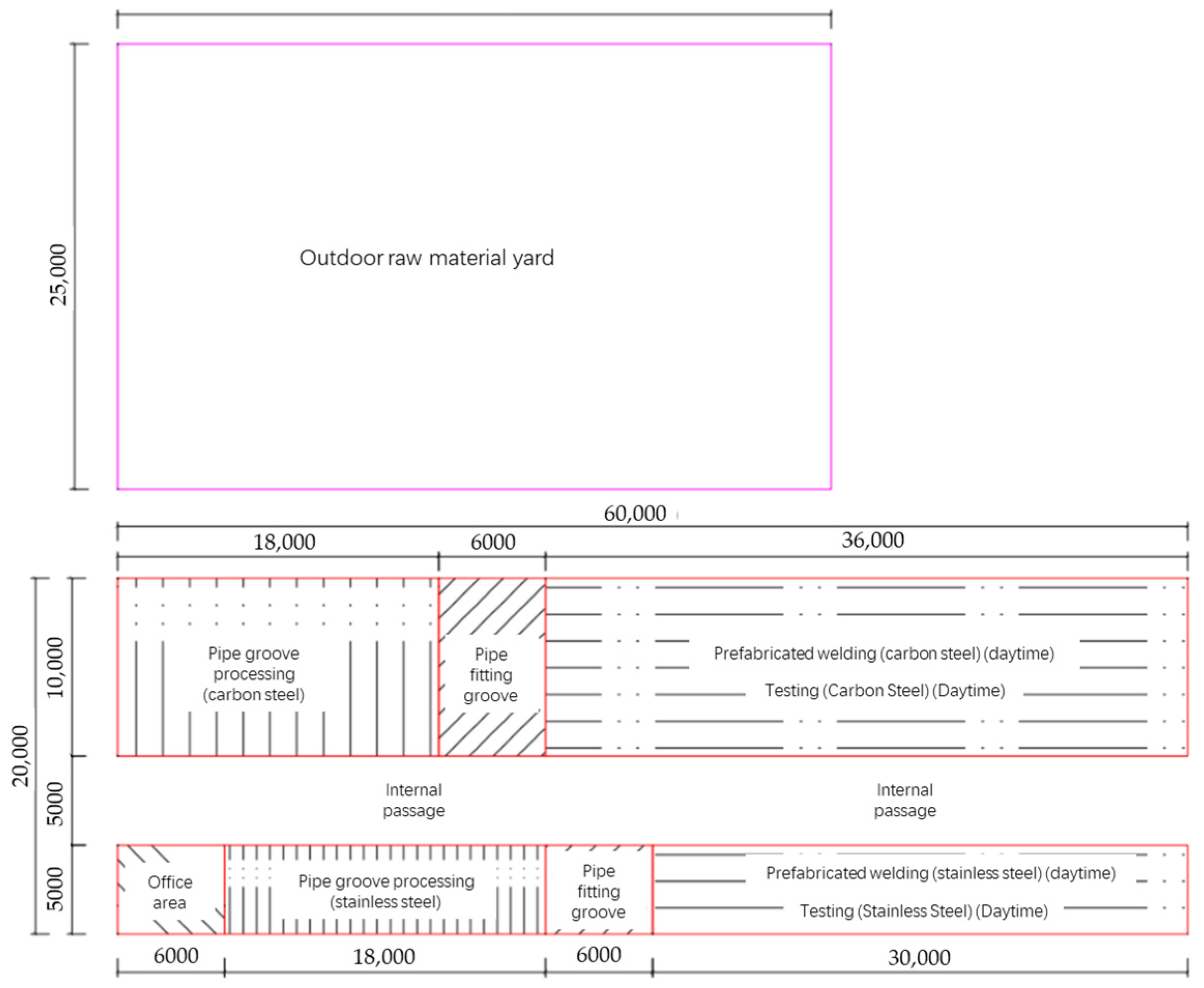
3.1.1. Site Selection and Layout of Prefabrication Factory

Due to requirements like size limitations for prefabricated pipe fittings, transportation needs, on-site road conditions, and transportation management regulations, prefabrication factories for pipeline stations are generally built near construction sites or material transfer stations [35,36].
(1) Requirements for site selection and layout of prefabrication sites
Priority should be given to areas close to the construction site and the campsite, with convenient transportation, short transportation distance, good geological conditions, and small foundation treatment volume. Rainy season flood discharge and sandstorm protection should also be considered comprehensively. The site layout needs to meet the requirements of industrialized assembly line operations, ensure reasonable workshop positioning and smooth roads to reduce secondary handling, implement drainage and dust storm prevention measures simultaneously, fully harden key areas, and keep high noise and radiation operation areas away from densely populated areas. Road planning in the site area should ensure that the main/branch roads meet the transportation requirements of large equipment and pipe fittings. Cranes, forklifts, and flatbed trucks should be reasonably equipped, and the walking route should be planned. The size of the workshop entrance and exit must meet the actual construction needs. Special waste and industrial waste disposal sites must also be established to strictly prevent environmental pollution.
(2) Requirements for the setting of prefabricated factory buildings
The height, width, materials, and internal facilities of the workshop building must meet the construction and regulatory standards. The layout should achieve a streamlined operation of material requisition, assembly, welding, testing, pressure testing, anti-corrosion, and shipping. Compliance with temporary power, lighting, ventilation, and grounding systems regulations should be ensured, and all types of safety warning signs should be complete. The welding rod drying warehouse and pipe fitting warehouse need to be managed by dedicated personnel, and a drying distribution ledger should be established and clearly labeled.
(3) Overall planning of prefabrication factory
According to the classification of long-distance pipeline stations, they mainly include compressor stations, distribution and cleaning stations, distribution stations, valve chambers, etc. According to statistical data, the welding volume of a single distribution station is between 10,000 and 15,000 inches, the welding volume of a cleaning station is between 45,000 and 55,000 inches, and the welding volume of a compressor station is between 80,000 and 90,000 inches. Calculated based on a prefabrication rate of over 70%, the welding period of a general station is 2–3 months. Therefore, the prefabrication capacity of the required prefabrication factory is 1000 inches/day. Therefore, considering such prefabrication factory capacity, the overall planning of the prefabrication factory needs to be carried out according to the following scale.
The planned factory building is 60 m long and 20 m wide, with an external storage yard of approximately 1000 m2. The open-air raw material pipeline yard is mainly used to store various finished steel structures and pipe fittings, and a crane with a load of 10 tons and a boom length of 18 meters is installed in the area. Prefabricated welding is mainly used for the matching and welding of prefabricated pipe fittings in the station yard. One cutting system and six inverter welding machines are set up in the area for the pipeline argon arc welding base and welding, and one piece of heat treatment equipment is used for weld bead heat treatment. There are three oxygen magnetic cutting machines installed in the groove processing area for manual cutting and groove processing of pipes. The testing area and the prefabricated welding area share the same site, and testing needs to be carried out at night when no one is in other areas [37,38].
The layout of the pipeline prefabrication workshop area includes one outdoor material storage area outside of the workshop. There are 4 break processing areas, 2 prefabricated welding inspection areas, and 1 office in the workshop. The specific layout is shown in Figure 12.

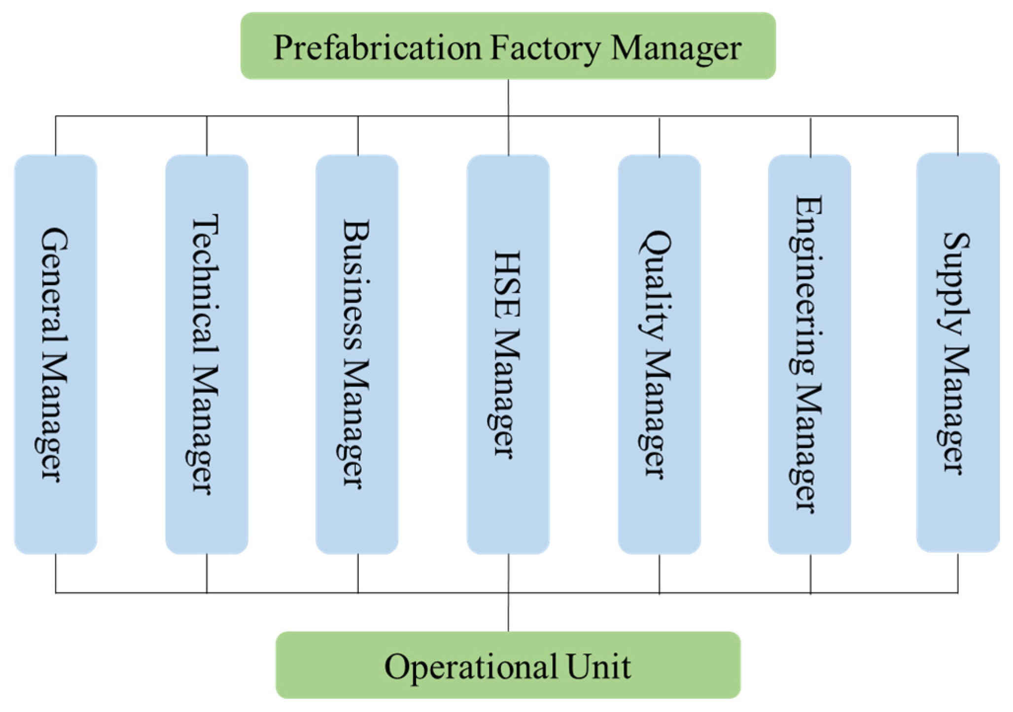
3.1.2. Equipment Configuration and Management Organization

According to the preset prefabrication scale of the prefabrication factory and the welding requirements of the process pipelines in the oil and gas station, the production line equipment of the prefabrication factory needs to meet the following requirements [39,40].
(1) Suitable pipe diameter: DN50–DN1200;
(2) Processing wall thickness: 3–60 mm;
(3) Raw material pipe length: ≤12 mm;
(4) Processing material: Suitable for processing various types of carbon steel, alloy steel, stainless steel, etc.;
(5) Processing technology: Groove processing technology: DN50–400 adopts cutting groove integrated processing, mechanical cold cutting processing, and a CNC cutting groove machine for cutting and groove one-time processing, with extremely high processing efficiency, meeting the high-speed processing requirements of conventional wall thickness V-shaped grooves. The DN300–1200 adopts band saw cutting and a CNC high-speed beveling machine for beveling processing, meeting the processing requirements of various wall thicknesses and beveling forms, such as V, U, X, double V, V + U, and double V + U, as well as fully automatic processing of internal bevels, internal boring holes, flat end faces, etc. For the automatic welding process, it includes argon arc automatic base and fine wire submerged arc automatic filling and covering.
The main equipment of the prefabrication factory is shown in Table 4.
As a fixed equipment processing and manufacturing site, the prefabrication factory requires specialized personnel, equipment, processing, and production management. Therefore, a matching organizational structure is needed for management. The organizational structure diagram required for the prefabrication factory is shown in Figure 13.

3.2. Construction Organization and Quality Management

3.2.1. Factory Prefabrication Construction Process

The production and operation process of the factory prefabrication system for oil and gas station pipelines can be mainly divided into six parts: technical preparation, raw material procurement, pipeline prefabrication, inspection and testing, packaging and transportation, and delivery and acceptance [41,42]. The factory prefabrication construction process is shown in Figure 14.
(1) Technical preparation: Designers prepare pipeline prefabrication documents according to project requirements, including single pipe drawings, axonometric drawings, layout plans, and construction instructions. The content of the single pipe diagram includes the pipeline number, starting and ending point coordinates, installation slope and medium flow direction, valve/special component location and positioning, support and hanger location and positioning, pipeline and equipment interface information, pressure boundary points, etc. The construction instructions should clearly specify the technical requirements for pipeline prefabrication tolerances, welding, heat treatment, inspection, corrosion prevention, packaging, and transportation.
(2) Raw material procurement: The procurement must strictly meet the requirements of the design data sheet and technical specifications, and the quality must comply with relevant specifications. Material substitution must be approved by the owner or designer. Acceptance procedure: Verify the “three certificates”, check the factory mark, appearance inspection, check the specifications and materials, material re-inspection, identification, and storage and preservation.
(3) Pipeline prefabrication: The main process is single pipe drawing inspection, sandblasting rust removal, painting primer, grinding groove, cleaning inside of the pipe, and assembly. Construction must strictly follow the single pipe diagram, and the deviation of the finished product must comply with the “Technical Specification for Factory Prefabrication of Pipelines” (HG/T21641-2013) [43].
(4) Inspection and testing: The prefabricated products are inspected by dedicated quality inspectors. The inspection includes the following:
① Appearance inspection: Checking the structural dimensions of the pipe fittings, the installation direction of the valve, the connection form (flange, thread, welding, etc.), and the quality of the groove at both ends one by one.
② Weld seam inspection: Conducting a visual inspection first, and only after passing the inspection can non-destructive testing be carried out. The radiographic/ultrasonic testing requires that the weld quality reach level II or above.
③ Surface testing: For specific welds that cannot be subjected to radiographic/ultrasonic testing (such as socket welds, branch pipe connection welds, reinforcement ring welds, sealing welds, support and hanger welds, etc.), carbon steel pipes shall be subjected to magnetic particle or penetrant testing in accordance with SY/T4109 [44], and stainless steel pipes shall be subjected to penetrant testing in accordance with NB/T47013 [45], with Class I qualification. The detection ratio is consistent with the non-destructive testing of the main pipeline.
④ Bend detection: For pipelines with extremely hazardous fluids or design pressures ≥ 10 MPa, surface non-destructive testing should be performed on each bend piece, and external ultrasonic testing should be added if necessary. Nickel low-temperature steel, chromium molybdenum alloy steel, and stainless steel bent pipes need to undergo material re-inspection and provide non-destructive testing reports after passing the inspection.
⑤ Hardness testing: Conducting hardness testing on welded joints and bent pipes after heat treatment.
(5) Packaging and transportation: Before painting for protection, thoroughly cleaning the inner and outer surfaces of the steel pipe and making necessary markings. Properly packaging according to transportation requirements to prevent collision, compression, and deformation during transportation.
(6) On-site acceptance: The owner (ordering unit) or its commissioned on-site construction unit is responsible for inspecting and accepting the prefabricated pipes upon arrival.

3.2.2. Construction of Quality Assurance System

(1) Quality objectives
① The quality qualification rate of engineering equipment and materials is 100%;
② The installation accuracy of pipelines with different materials, materials, and anti-corrosion coatings is 100%;
③ The accuracy of numbering for valves, bends, elbows, tees, and other pipe fittings is 100%;
④ The first pass qualification rate of pressure pipeline welding is 95% or above;
⑤ The qualified rate of pipeline burial depth is 100%;
⑥ The certification rate for special job operators is 100%.
(2) Quality Assurance System
Based on the characteristics of prefabrication factories, a quality assurance system for prefabricated process pipelines is established as shown in Figure 15.
(3) Quality control elements
The quality control elements for the welding and installation of process pipelines are shown in Table 5.
For key quality control points, the following pre-control measures have been developed.
Prefabrication of process pipelines: Verify pipes, welding materials, fittings, valves, welding materials, and quality assurance documents. The pipeline must be cleaned and inspected before cutting. Groove processing should be carried out according to material requirements, including flame cutting, mechanical processing, and polishing. Welders must hold valid certificates and strictly adhere to welding specifications. Strictly implement the system of electrode storage, drying, and distribution. Weld seam inspection requires qualified inspection before leaving the site.
Process pipeline installation: Pipe fittings, valves, etc. should be checked for accuracy according to design requirements, and valves should be pressure tested according to regulations. Whether the slope direction, gradient, and support hangers of pipeline installation comply with the requirements of the drawings and specifications should be checked. The parallelism and coaxiality of flanges connected to machines and equipment should be within the allowable tolerance. Check cleanliness at every step of the pipeline installation process.
Welding: Verify material certification. A secondary warehouse should be established at the construction site, with standardized stacking and dedicated personnel responsible for it. Establish rules and regulations for signing, drying, issuing, receiving, and using. Welders must hold certificates before taking up their posts. Strictly implement the welding process specifications. The construction site should have windproof, rainproof, snow-proof, and cold-proof facilities. The proportion and location requirements for weld inspection should be entrusted to technicians according to design and specifications and supervised by quality inspectors.

3.3. Supply Chain Management and Information Technology Applications

3.3.1. Supply Chain Collaboration

The station engineering of different projects has a large amount of data and information accumulation for material demand planning, procurement, installation, and maintenance, but there is no centralized and unified management and application, and many edge data have not been utilized. Applying big data intelligent technology to procurement management can leverage the powerful functions of big data to expand horizontally to external data and vertically to various stages, such as material planning, procurement review, and supplier management. This is specifically reflected in the procurement strategy, supplier selection, and warehouse material control optimization. Scientifically configuring important links in the entire supply chain by utilizing big data technologies, such as deep data mining, cloud computing, and intelligent analysis, can improve procurement quality, achieve precise procurement, reduce operating costs, and enhance enterprise economic benefits [46,47].
(1) Procurement Strategy
By summarizing and analyzing the specifications and models of station equipment, procurement requirements, estimated procurement quantities, suppliers, equipment inventory, transactions, warehousing, equipment loss and usage data, equipment maintenance data, etc., the material and procurement rules are calculated, and the demand rules for equipment in different projects and periods are intelligently calculated and predicted. And, it is possible to compare and feed back the estimated quantity data with the actual demand quantity, delivery situation, and equipment usage situation of the equipment so as to form a closed loop between the estimated demand quantity and the actual demand and improve the efficiency and accuracy of the pre-estimated quantity prediction in the procurement work.
(2) Supplier selection
By combining big data intelligent computing and modeling technology, a comprehensive supplier dynamic control evaluation index system is established. Based on the characteristics of suppliers, clustering analysis is carried out, and, combined with supplier historical information, supplier behavior analysis and evaluation results are obtained to effectively analyze their behavior trends. And, it is possible to use supervision algorithms to construct a digital model for supplier behavior warning, establish a supplier information database, objectively and comprehensively understand the supplier’s credit capability and integrity through multiple channels, monitor and predict supplier behavior in real time, and achieve scientific evaluation and refined management of suppliers.

3.3.2. Information Management Platform

A video surveillance system can be deployed on the prefabricated factory site to monitor the overall situation and the operation status of each key process in real time, strengthen the supervision of on-site construction, make the quality behavior of key processes traceable and searchable, and improve the overall quality control level. It is possible to cooperate with the owner unit to build a video surveillance service platform equipped with CVR for video storage and playback [48]. Prefabrication units need to refer to the construction scope of smart construction sites. Smart construction sites need to build video surveillance on the welding unit working surface and inside of the welding shed and be equipped with NVR and storage cards for on-site data storage. Control balls should be placed on the roof of the warm shed to monitor the construction working surface. The cameras inside of the welding shed should adjust their angles according to the actual situation [49,50].
Based on the equipment archive, the prefabricated construction management assistant is applied to carry out closed-loop management of equipment inspection, entry, maintenance, calibration, on-site inspection, and exit. The construction process management diagram of electronic tags is shown in Figure 16.

4. Analysis of Factory Prefabrication Application

4.1. Application Project Overview

This study selects the newly built gas transmission station A of a natural gas pipeline project as a case study for in-depth analysis. The design pressure of the compressor station is 10MPa, the design temperature is −15.8~70 °C, the natural gas inlet flow rate is 4800–9600 × 104 Nm3/d, and the outlet flow rate is 2100~5700 × 104 Nm3/d. It is equipped with 20 MW electric drive with two in use and one backup compressor unit. Three units were built at once in 2024 and are planned to be put into operation in 2025. There are four DN500 filter separators installed in the station, which are connected in parallel to meet the design requirements. There are five in use and two as backup DN400 ultrasonic flow meters and a 25 m high DN600 non-ignition vent riser. The average daily minimum temperature in the construction area is −13.40 °C, with a minimum operating temperature of 5.1 °C and a maximum operating temperature of 50 °C. In the early stages of project initiation, traditional on-site construction methods faced many challenges. The local climate conditions are complex, with high temperatures and heavy rainfall in summer and cold and windy winters, which have brought great inconvenience to on-site construction and seriously affected construction progress and quality. The narrow site and limited construction space make it difficult to stack materials and park equipment, which increases the difficulty of construction management. At the same time, with the rapid growth of demand in the natural gas market, project construction schedules are tight, and traditional construction methods have difficulty meeting the requirements of on-time production. To overcome these difficulties, the A station adopts a factory prefabrication scheme, with a prefabrication rate of 70% for DN50~DN600 pipelines in the station. Furthermore, 80% of the welds are automatically welded, and prefabricated parts are transported through dedicated brackets to reduce the number of on-site lifting operations. The quality and efficiency of project construction are improved by adopting a factory prefabrication scheme for construction.

4.2. Implementation of Factory Prefabrication Plan

In the implementation process of the plan, firstly, based on the applicable scope requirements of factory prefabrication, various types of pipelines in the station are carefully sorted and classified. For small and medium-sized main pipelines, secondary pipelines, and some prefabricated accessories that meet the conditions for factory prefabrication, precise prefabrication pipe section division should be carried out to determine their specifications, sizes, and lengths, and the specifications of raw materials should be fully considered to reduce waste generation.
In terms of prefabricated factory construction, according to the workshop layout plan, a fully functional prefabricated workshop should be built. A reasonable layout includes areas for breaking processing, prefabrication welding inspection, etc. in the workshop equipped with advanced processing and inspection equipment, such as high-precision CNC cutting band saws, automatic welding machines, etc., to ensure the smooth progression of prefabrication work.
In the technical preparation stage, the design team carefully completes various design documents, specifies the parameters and technical requirements of the pipeline in detail, and conducts comprehensive technical disclosure to the construction personnel. In the raw material procurement process, suppliers are strictly screened to ensure superior material quality, and each batch of materials is rigorously inspected according to the acceptance procedures. During the pipeline prefabrication process, workers strictly follow the single pipe diagram for construction and finely control each process to ensure the quality of prefabrication. At the same time, it is important to strengthen the inspection and testing of prefabricated pipelines, increase the frequency and items of inspection, and ensure that every prefabricated pipe section meets quality requirements. During packaging and transportation, appropriate packaging materials and transportation methods should be selected based on the characteristics of the pipeline to ensure that prefabricated pipe sections are not damaged during transportation. The process analysis and indicator measurement of the factory prefabrication plan are shown in Table 6.

4.3. Implementation Effect Evaluation

4.3.1. Comparison of Project Duration

Compared with conventional construction evaluations, prefabrication factories use less manual labor than conventional on-site welding, and they can solve the problem of an inability to cross-operate on site. Prefabrication can be started in advance before the completion of on-site civil construction and transported directly to the site for assembly and welding after the construction conditions are met, which can greatly shorten the overall construction period of the station.
The calculation of the proportion of shortened construction period is shown in Equation (1).
S T = T C T P T C × 100 %
In the formula, ST is the duration reduction ratio; TC is the regular construction period; and TP stands for Factory Prefabrication Schedule.
The comparison of factory prefabrication and conventional construction efficiency is shown in Table 7. The efficiency of prefabrication factories is mainly in the secondary transportation of prefabricated components compared to on-site construction time. The usage period of prefabrication factories in other aspects is relatively short compared to on-site construction. Therefore, in the case of a large amount of welding work, choosing factory prefabrication has obvious advantages in terms of construction period and cost.

4.3.2. Quality Assessment

The quality of pipe fittings’ welds must meet the following requirements. In terms of appearance, the appearance of the weld should be uniform and consistent, and the width of the weld should be increased by 1.0~2.0 mm on each side compared to the width of the outer surface groove. The excess height of the weld seam should not exceed 2 mm, and the continuous length can exceed 2 mm but should not exceed 3 mm and should not exceed 50 mm. There should be no cracks, lack of fusion, pores, arc marks, harmful weld beads, pits, or fixture welding points on the weld seam and its adjacent surfaces. When the cover weld is a row weld, the bottom of the groove between adjacent welds should be higher than the base metal, and the depth of the groove between welds (the height difference between the weld and adjacent grooves) should not exceed 1.0 mm; the depth of the undercut should not exceed 0.5 mm. If the depth of the undercut is less than 0.3 mm, any length qualifies. For the depth of undercutting between 0.3 and 0.5 mm, the individual length should not exceed 30 mm. Within any 300 mm continuous length of the weld seam, the cumulative length of the undercutting should not exceed 50 mm; the cumulative length should not exceed 15% of the circumference of the weld seam. In terms of non-destructive testing, the quality of welded joints is divided into four levels, and the level determination criteria should comply with the provisions of SY/T 4109. Level II or above is considered to qualify.
The calculation of the one-time welding qualification rate is shown in Equation (2).
R P = N 1 N T × 100 %
In the formula, Rp is the first welding qualification rate; N1 is the number of welds that pass the one-time inspection; and NT is the total number of welds.
After adopting the factory prefabrication scheme, the contact compressor station A achieved good results in the implementation of the factory prefabrication scheme due to the stable environment and advanced equipment in the factory, which greatly improved the welding quality. A comprehensive inspection was conducted regarding the appearance’s quality, geometric dimensions, and the internal quality of prefabricated pipe fittings.
The surface of the pipe fittings is free of defects, such as cracks, sand holes, air holes, slag inclusions, and undercutting. The weld surface is flat and smooth, with no obvious welding defects. The diameter, wall thickness, and length of the pipe fittings meet the design requirements, and the deviation is within the allowable range.
The welding seams of the pipe fittings have passed non-destructive testing, and the welding pass rate has reached over 96%, which is significantly higher than traditional construction methods, effectively reducing the probability of safety hazards, such as leaks during pipeline operation. The strict construction process and quality inspection system ensure the quality stability of each prefabricated pipe section, enhancing the reliability of the entire pipeline system and effectively ensuring the long-term stable operation of the oil and gas station.

4.3.3. Cost Analysis

Considering the prefabrication scheme of process pipelines in compressor station A, after adopting the prefabricated pipe section scheme, about 70% of the welded joints of the process pipelines in the station will be installed and tested in the prefabrication plant, and small-diameter valves and fittings will also be installed and tested in the prefabrication plant. The investment is calculated based on labor, electricity consumption, and water consumption costs for installation in the prefabrication plant. The transportation cost mainly considers the cost of prefabricated components from the prefabrication factory to the construction site, with a transportation distance of 100 km. The cost comparison between the factory prefabrication scheme and the conventional scheme is shown in Table 8.
From a cost perspective, the project has achieved significant cost savings during the construction process by adopting a factory prefabrication scheme. Compared to traditional on-site construction methods, the installation cost of factory prefabricated pipelines has been significantly reduced. In compressor station A, the pipeline installation cost of the prefabricated scheme was reduced by CNY 3.45 million compared to the conventional scheme. In terms of transportation costs, although the transportation of prefabricated parts has increased to some extent, considering the improvement of on-site construction efficiency, the reduction of labor costs, and the reduction of rework costs due to quality improvement, the overall cost is still effectively controlled. In this project, after comprehensive calculation of various costs, the prefabrication scheme has significant cost savings compared to the conventional scheme, fully reflecting the advantages of factory prefabrication in cost control. With the increase in prefabrication quantity, the economic benefits will become more significant.

5. Conclusions

This study systematically verified the core advantages of factory prefabrication technology in pipeline construction at oil and gas stations. By integrating key technologies, such as 3D digital design, automated welding processes, intelligent non-destructive testing, and modular transportation, a technical system covering the entire design, production, testing, and transportation chain has been constructed. A management mode centered on prefabrication factory planning, quality control, and supply chain collaboration has been established to enhance the transparency and traceability of the construction process.
Research has shown that the prefabrication rate of DN50–DN600 pipelines reaches 70%, automated welding accounts for 80%, the total construction period is shortened by about 36%, and efficiency is significantly improved. The coverage rate of non-destructive testing is 100%, the pass rate of welding is over 96%, and the quality is comprehensively optimized. Large-scale production reduces raw material loss by 10%, reduces full lifecycle costs by 15%, saves CNY 3.45 million in case projects, and effectively controls costs. BIM and IoT platforms enable visual traceability of the entire construction process, leading to deep management innovation and effectively reducing safety accident rates.
Although this study has made economic and technological progress, current technology promotion still faces some challenges. Large-diameter pipelines above DN600 are constrained by transportation conditions and have insufficient prefabrication rates, requiring on-site welding repairs. Cross-project and cross-process technology adaptability still require standard support. The optimization of welding parameters and quality inspection rely heavily on manual experience.
Looking ahead to the future, factory prefabrication of oil and gas station pipelines will further develop on-site automated welding robots suitable for large-diameter pipelines, deepen the application of artificial intelligence and new material technology, and fill the boundary of factory prefabrication. It will also explore the deep integration of phased array ultrasound and AI defect recognition to achieve real-time judgment of welding inspection results, establish a cross-project modular database, promote standardized design of prefabricated components, and achieve full industry chain collaboration of prefabricated factories. It is continuously playing a more important role in ensuring energy security, optimizing engineering efficiency, and promoting the industry’s transformation towards intelligence and a green direction.

Author Contributions

Conceptualization, S.L. and Y.C.; methodology, P.M.; software, X.Y.; validation, W.Y., S.L. and Y.C.; formal analysis, S.Y.; investigation, G.Z.; resources, C.C.; data curation, M.Z.; writing—original draft preparation, L.W. and Y.C.; writing—review and editing, L.W.; visualization, S.L.; supervision, Y.C.; project administration, X.Y. and H.J.; funding acquisition, L.W. All authors have read and agreed to the published version of the manuscript.

Funding

This research received no external funding.

Data Availability Statement

The original contributions presented in this study are included in the article. Further inquiries can be directed to the corresponding author.

Conflicts of Interest

Authors Shaoshan Liu, Yi Chen, Pingping Mao, Huanyong Jiang, Xubo Yao and Weitao Yao were employed by the PipeChina Engineering Technology Innovation Co., Ltd. Authors Shuangjie Yuan and Guochao Zhao were employed by the China National Petroleum Pipeline Engineering Co., Ltd. The remaining authors declare that the research was conducted in the absence of any commercial or financial relationships that could be construed as a potential conflict of interest.

Abbreviations

The following abbreviations are used in this manuscript:
DNNominal Diameter
BIMBuilding Information Modeling
P&IDPiping and Instrumentation Diagram
DECPipeChina Design and Engineering Code
IoTInternet of Things
CNCComputerized Numerical Control
GTAWGas Tungsten Arc Welding
GMAWGas metal arc welding
FCAWFlux-Cored Arc Welding
SAWSubmerged arc welding
AUTAutomated Ultrasonic Testing
PAUTPhased array ultrasonic testing
DRDigital Ray
CVRCentral Video Recorder
NVRNetwork Video Recorder

References

  1. Jiang, C.L. Quality control and safety management of oil and gas pipelines during its whole life cycle. Oil Gas Storage Transp. 2023, 42, 1081–1091. [Google Scholar]
  2. Sun, Y.; Yu, S.; Wang, B.; Gu, T. Numerical Analysis and Optimization of Residual Stress Distribution in Lined Pipe Overlay Welding. Processes 2025, 13, 1548. [Google Scholar] [CrossRef]
  3. O’Grady, T.M.; Brajkovich, N.; Minunno, R.; Chong, H.-Y.; Morrison, G.M. Circular Economy and Virtual Reality in Advanced BIM-Based Prefabricated Construction. Energies 2021, 14, 4065. [Google Scholar] [CrossRef]
  4. Wang, L.; Jiao, Z.L.; Zhu, F. Problems in building the One Pipeline Network of oil and gas and discussion on methodology. Oil Gas Storage Transp. 2022, 41, 1260–1268. [Google Scholar]
  5. Xu, Z.; Wang, X.; Rao, Z. Automated Optimization for the Production Scheduling of Prefabricated Elements Based on the Genetic Algorithm and IFC Object Segmentation. Processes 2020, 8, 1593. [Google Scholar] [CrossRef]
  6. Li, C.; Lu, P.; Zhu, W.; Zhu, H.; Zhang, X. Intelligent Monitoring Platform and Application for Building Energy Using Information Based on Digital Twin. Energies 2023, 16, 6839. [Google Scholar] [CrossRef]
  7. Zheng, C. Application of Factory Prefabrication of Pipelines in Engineering. Chem. Des. 2020, 30, 23–25+1. [Google Scholar]
  8. López-Molina, A.; Sengupta, D.; Shi, C.; Aldamigh, E.; Alandejani, M.; El-Halwagi, M.M. An Integrated Approach to the Design of Centralized and Decentralized Biorefineries with Environmental, Safety, and Economic Objectives. Processes 2020, 8, 1682. [Google Scholar] [CrossRef]
  9. Korkas, C.; Dimara, A.; Michailidis, I.; Krinidis, S.; Marin-Perez, R.; Martínez García, A.I.; Skarmeta, A.; Kitsikoudis, K.; Kosmatopoulos, E.; Anagnostopoulos, C.-N.; et al. Integration and Verification of PLUG-N-HARVEST ICT Platform for Intelligent Management of Buildings. Energies 2022, 15, 2610. [Google Scholar] [CrossRef]
  10. Kim, J.; Kim, J.; Pyo, C. A Study on Fiber Laser Welding of High-Manganese Steel for Cryogenic Tanks. Processes 2020, 8, 1536. [Google Scholar] [CrossRef]
  11. Zhao, S.X. Key points of technical preparation for automatic welding of longdistance oil and gas pipelines. Oil Gas Storage Transp. 2021, 40, 1409–1415. [Google Scholar]
  12. Wang, Y.; Song, F.; Feng, Q.; Qiao, W.; Dong, S.; Jiang, Y.; Ma, Q. Basic Theory and Applications of Oil and Gas Pipeline Non-Destructive Testing Methods. Energies 2024, 17, 6366. [Google Scholar] [CrossRef]
  13. Zhao, Y.; Noori, M.; Altabey, W.A.; Ghiasi, R.; Wu, Z. Deep Learning-Based Damage, Load and Support Identification for a Composite Pipeline by Extracting Modal Macro Strains from Dynamic Excitations. Appl. Sci. 2018, 8, 2564. [Google Scholar] [CrossRef]
  14. Akram, S.; Bertilsson, K.; Siden, J. LTspice Electro-Thermal Model of Joule Heating in High Density Polyethylene Optical Fiber Microducts. Electronics 2019, 8, 1453. [Google Scholar] [CrossRef]
  15. Liu, X.Y. Overview of the Industrialization of Pipe Prefabrication. China Chem. Trade 2013, 8, 372–373. [Google Scholar]
  16. Liu, Y.; Xie, W.; Guo, Q.; Wang, S. Enhancing Pipeline Leakage Detection Through Multi-Algorithm Fusion with Machine Learning. Processes 2025, 13, 1519. [Google Scholar] [CrossRef]
  17. Gonçalves, P.T.; Arteiro, A.; Rocha, N. End-to-End Simulation of Linerless Composite Pressure Vessels Using 3D Continuum Damage Models. J. Compos. Sci. 2024, 8, 504. [Google Scholar] [CrossRef]
  18. Polo, S.; Rubio, E.M.; Ayllón, J.; de Agustina, B. Emerging Advances in Sustainable Manufacturing. Processes 2025, 13, 1549. [Google Scholar] [CrossRef]
  19. Zhang, M.; Jiang, Y.; Wan, C.; Tang, C.; Chen, B.; Xi, H. Design of an Intelligent Shop Scheduling System Based on Internet of Things. Energies 2023, 16, 6310. [Google Scholar] [CrossRef]
  20. Sun, L.; Meng, X.; Xu, J.; Tian, Y. An Image Segmentation Method Using an Active Contour Model Based on Improved SPF and LIF. Appl. Sci. 2018, 8, 2576. [Google Scholar] [CrossRef]
  21. Sang, Y.; Tan, J. Many-Objective Flexible Job Shop Scheduling Problem with Green Consideration. Energies 2022, 15, 1884. [Google Scholar] [CrossRef]
  22. Li, B.S.; Wang, X.L.; Xu, B. Operation and management status and intelligentization trend of global oil and gas pipelines. Oil Gas Storage Transp. 2019, 38, 241–250. [Google Scholar]
  23. Li, Y.F.; Li, J.Y.; Jia, Z.Q. Application of Modular Design in Pipeline Station Construction. Transp. Enterp. Manag. 2017, 3, 70–80. [Google Scholar]
  24. Startsev, A.E.; Bakhmatov, V.P. Effect of Automatic Arc Welding Conditions on the Geometric Parameters of Low-Carbon Steel Welded Butt Joints Made Using an Experimental Flux. Russ. Metall. (Met.) 2025, 2024, 1925–1933. [Google Scholar] [CrossRef]
  25. Zhang, Y.; Wu, S.; Cheng, F. Automatic Adaptive Weld Seam Width Control Method for Long-Distance Pipeline Ring Welds. Sensors 2025, 25, 2483. [Google Scholar] [CrossRef] [PubMed]
  26. Sacarea, A.I.; Oancea, G.; Parv, L. Magnetic Particle Inspection Optimization Solution within the Frame of NDT 4.0. Processes 2021, 9, 1067. [Google Scholar] [CrossRef]
  27. Zhang, F.; Li, H.Q.; Wang, Y. Modular Design and Application of Buildings for Long distance Pipeline Stations. Oil Gas Storage Transp. 2012, 10, 31–33+37+95. [Google Scholar]
  28. Lin, Y.; Liu, H.; Yu, J. Non-destructive testing of metal/CFRP composite defects using continuous-wave laser ultrasonic technique. Opt. Laser Technol. 2025, 189, 113113. [Google Scholar] [CrossRef]
  29. Dmytrakh, M.I.; Syrotyuk, M.A.; Mokryi, M.O. Comparison of applicability of different nondestructive testing methods for assessing hydrogen concentration in carbon steel. Mater. Sci. 2025, 60, 1–7. [Google Scholar] [CrossRef]
  30. Zhang, D.L.; Zhang, Y.; He, M. Development and application of 3D desktop cloud system for long-distance pipeline. Oil Gas Storage Transp. 2016, 35, 875–881. [Google Scholar]
  31. Wang, Z.; Gao, Y.; Gao, Y. Optimization of Distributed Photovoltaic Energy Storage System Double-Layer Planning in Low-Carbon Parks Considering Variable Operating Conditions and Complementary Synergy of Energy Storage Devices. Energies 2025, 18, 1881. [Google Scholar] [CrossRef]
  32. Jin, H.; Zhang, M.; Yuan, Y. Analytic Network Process-Based Multi-Criteria Decision Approach and Sensitivity Analysis for Temporary Facility Layout Planning in Construction Projects. Appl. Sci. 2018, 8, 2434. [Google Scholar] [CrossRef]
  33. Tian, Y.F.; Liao, H.; Mi, W. Application of Skid Loading Design in Long distance Natural Gas Pipeline Stations. Pet. Plan. Des. 2018, 29, 34–36,45. [Google Scholar]
  34. He, G.L. The prospects and bottlenecks of factory prefabrication of pipelines. Installation 2015, 16–17. [Google Scholar]
  35. Liu, P.H.; Zhao, Y.N. The current situation and development trend of pipeline prefabrication factory. Encycl. Forum Electron. Mag. 2019, 769. [Google Scholar]
  36. D’Oca, S.; Ferrante, A.; Ferrer, C.; Pernetti, R.; Gralka, A.; Sebastian, R.; Op ‘t Veld, P. Technical, Financial, and Social Barriers and Challenges in Deep Building Renovation: Integration of Lessons Learned from the H2020 Cluster Projects. Buildings 2018, 8, 174. [Google Scholar] [CrossRef]
  37. Wang, Z.S. Advantages and Applications of Remote Factory Prefabrication of Process Pipelines. Petrochem. Constr. 2019, 041, 46–50. [Google Scholar]
  38. Pučko, Z.; Maučec, D.; Šuman, N. Energy and Cost Analysis of Building Envelope Components Using BIM: A Systematic Approach. Energies 2020, 13, 2643. [Google Scholar] [CrossRef]
  39. Chang, J.H. Application of Pipe Prefabrication Industrialization in the ASAB3 Project in the United Arab Emirates. Petrochem. Constr. 2017, 4, 60–63. [Google Scholar]
  40. Lin, S.; Huang, X.; Zhang, S.; Han, Z. Ensemble Learning-Based Approach for Forecasting Inventory Data in Prefabricated Component Warehousing. Processes 2025, 13, 1443. [Google Scholar] [CrossRef]
  41. Cao, Y.S. Application of Factory Prefabrication of Pipelines in Engineering Construction. Procure. Pet. Petrochem. Mater. 2018, 36, 14. [Google Scholar]
  42. Wu, S.J.; Chi, Z.C. Application of Factory Prefabrication Technology in Industrial Pipeline Installation. Installation 2014, 36–38. [Google Scholar]
  43. HG/T 21641; Technical Specification for Factory Prefabrication of Pipelines. The Ministry of Industry and Information Technology of the People’s Republic of China. Chemical Industry Press: Beijing, China, 2013.
  44. SY/T 4109; Non Destructive Testing of Oil and Gas Steel Pipelines. National Energy Administration. Petroleum Industry Press: Beijing, China, 2020.
  45. NB/T 47013.3; Non Destructive Testing of Pressure Equipment. National Energy Administration. Beijing Science and Technology Press: Beijing, China, 2024.
  46. Cagno, E.; Accordini, D.; Thollander, P. Energy management and industry 4.0: Analysis of the enabling effects of digitalization on the implementation of energy management practices. Appl. Energy 2025, 390, 125877. [Google Scholar] [CrossRef]
  47. Chen, W. A Brief Discussion on Enhancing the Factory Prefabrication Capability of Pipeline on Project Sites. Shandong Ind. Technol. 2016, 14, 249. [Google Scholar]
  48. Wei, H.; Wu, T.; Sun, J. Analysis of the Role of Informative Construction Management System in Improving the Safety of Oil and Gas Pipeline Construction and Its Efficiency. Appl. Math. Nonlinear Sci. 2025, 10, 1–17. [Google Scholar] [CrossRef]
  49. Tang, D.H.K. Artificial Intelligence in Occupational Health and Safety Risk Management of Construction, Mining, and Oil and Gas Sectors: Advances and Prospects. J. Eng. Res. Rep. 2024, 26, 241–253. [Google Scholar] [CrossRef]
  50. Waqar, A.; Othman, I.; Lezcano, G.A.R. Challenges to the Implementation of BIM for the Risk Management of Oil and Gas Construction Projects: Structural Equation Modeling Approach. Sustainability 2023, 15, 8019. [Google Scholar] [CrossRef]
Figure 1. Pipeline prefabrication workshop.
Processes 13 01890 g001
Figure 2. Digital design process for station platform.
Processes 13 01890 g002
Figure 3. 3D model diagram of different areas in the station yard.
Processes 13 01890 g003
Figure 4. Typical installation diagram of inlet and outlet pipelines.
Processes 13 01890 g004
Figure 5. Typical installation diagram of large-diameter pipelines.
Processes 13 01890 g005
Figure 6. Typical prefabricated drawing for small- and medium-diameter pipelines.
Processes 13 01890 g006
Figure 7. Typical prefabricated drawing of secondary pipeline.
Processes 13 01890 g007
Figure 8. Design drawing of steel pipe and steel pipe docking joint groove.
Processes 13 01890 g008
Figure 9. Design drawing of butt joint groove for steel pipe and fittings (V-shaped groove).
Processes 13 01890 g009
Figure 10. Design drawing of joint groove for steel pipe and pipe fitting (U-shaped groove).
Processes 13 01890 g010
Figure 11. Schematic diagram of non-destructive testing for oil and gas pipelines.
Processes 13 01890 g011
Figure 12. Pipeline prefabrication workshop area layout.
Processes 13 01890 g012
Figure 13. Organization chart of prefabricated factory.
Processes 13 01890 g013
Figure 14. Factory prefabrication construction process.
Processes 13 01890 g014
Figure 15. Quality assurance system diagram for prefabricated components.
Processes 13 01890 g015
Figure 16. Schematic diagram of construction process management for electronic tags.
Processes 13 01890 g016
Table 1. Recommended application of automatic welding technology in stations.
MaterialPipe Diameter (mm)Wall Thickness (mm)Prefabricated Welding ProcessTypeGroove Type
Carbon steel, low alloy steelDN25–DN3003–8GTAW (automatic)Clamp type argon arc automatic weldingU-shaped
Carbon steel, low alloy steel≥DN300≥8GTAW root welding (automatic) + GMAW filling cover (automatic)Orbital argon arc automatic weldingU-shaped
Carbon steel, low alloy steel≥DN300≥8GTAW root welding (manual) + FCAW filling cover (automatic)Orbital argon arc automatic weldingV-shaped
Carbon steel, low alloy steel≥DN300≥8GTAW root welding (manual) + SAW filling cover (automatic)Submerged arc welding bracket roller toolingV-shaped
Stainless steelDN25–DN3003–8GTAW (automatic)Clamp type argon arc automatic weldingU-shaped
Table 2. Recommended application of non-destructive testing technology for station (valve room).
MaterialPipe Diameter (mm)Wall Thickness (mm)Testing ProcessGroove Type
Carbon steel, low alloy steel, stainless steelDN25–DN2503–8DR double wall double shadow/double wall single shadow + PAUTV-shaped
U-shaped
Carbon steel, low alloy steel, stainless steelDN300–DN500≥8DR double wall single shadow + PAUTV-shaped
Carbon steel, low alloy steel≥DN500≥8DR center radiography + PAUTV-shaped
Carbon steel, low alloy steel, stainless steelDN300–DN500≥8DR double wall single image + AUTU-shaped
Carbon steel, low alloy steel≥DN500≥8DR center radiography + UTU-shaped
Table 3. Comparison between factory prefabrication and conventional construction.
Comparison ItemsConventional ConstructionFactory Prefabrication
Environmental controlThe environment is greatly affected by natural conditions, such as temperature, humidity, wind, and narrow sites, making it uncontrollable.The factory environment is stable and controllable, with good working conditions to avoid interference from natural factors.
Quality controlManual welding relies on experience and has low detection coverage (such as difficulty in detecting concealed parts) and a high rate of weld defects.Full process quality management system, 100% non-destructive testing (X-ray/ultrasonic inspection), real-time monitoring of welding parameters.
Construction technologyOn-site dispersed operations, loose process connections, and low efficiency of manual welding (single weld seam takes several hours).Production line, automated welding (3–5 times faster), high precision of prefabricated components.
Construction timeAffected by weather and coordination, the construction period is prone to delays, and on-site welding interruptions are frequent.Prefabrication and on-site parallel construction have shortened the total construction period by about 30%, and the progress is highly controllable.
Cost structureHigh labor costs (high dependence on welders), high material waste rate, and a 30% increase in maintenance costs in the later stage. The materials are transported multiple times, resulting in high loss rates and high transportation costs.Large-scale production reduces raw material procurement costs by 10%, automated production reduces labor costs, and total lifecycle costs are reduced by 15%. Prefabricated parts are transported in a complete set with low loss rate.
Digital managementManually recording information leads to lagging progress and quality data, making it difficult to trace.Full process digital platform (BIM + IoT), real-time monitoring of production data, QR code traceability system.
Safety risksThere are many high-altitude operations, high risks of cross construction, and numerous safety hazards.Factory environment safety standards reduce on-site high-risk operations, resulting in a significant decrease in safety accident rates.
Resource consumptionThe on-site energy consumption is high, while the material utilization rate is low (about 85%), and the amount of waste generated is large.Intensive production reduces energy consumption, increases the material utilization rate to over 95%, and achieves high recycling efficiency.
On-site civil engineeringReserve space for pipeline prefabrication and occupy space.Parallel factory prefabrication and on-site civil engineering to reduce site conflicts.
Installation efficiencySingle tube welding takes a long time and requires on-site adjustment.Modular installation of prefabricated components, increasing efficiency by 50%.
Table 4. Main equipment configuration table of prefabricated factory.
EquipmentEquipment Functional Requirements
Plasma cutting machinePipeline fixed length cutting, groove cutting, straight/oblique intersecting line cutting, drilling, shrimp section cutting, 12 m raw material cutting
Multi-functional group pairingMechanized assembly of pipes, elbows, flanges, tees, and other fittings
CNC pipe cutting band saw machineDouble column gantry, left and right centering hydraulic self-centering clamping, cutting speed with infinitely variable frequency adjustment
CNC high-speed pipe beveling machineGroove processing, flat end face, internal boring processing, etc.
Cantilever Chuck Pipe Automatic Welding MachineAutomatic tungsten inert gas welding + submerged arc welding dual-use system
Compressed pipeline automatic welding machineAutomatic tungsten inert gas welding + submerged arc welding dual-use system
Table 5. Quality control elements for welding and installation of process pipelines.
TypeKey Quality Control Points
Prefabrication of process pipelinesMaterials; pipeline cleaning; groove processing; pipeline welding
Process pipeline installationPre-installation process inspection; on-site pipeline installation; fixed mouth welding; pipeline cleanliness
WeldingWelding materials; welding rod (wire) management; welding
Table 6. Process analysis and index measurement of prefabricated plant plan.
Project PhaseEngineering ProcessProcess Difference Analysis
Plant constructionSite layoutSite leveling, foundation treatment, road laying, water supply and drainage, power supply lines, signage, and other temporary facilities
BuildingWelding workshops, office facilities, etc.
Intelligent construction site construction
Prefabricated factory installationGroove processing
Pipeline loading and unloading, pipe stackingCheck equipment, pipeline hoisting in place, pipeline cutting, groove processing, automatic welding, pipeline transportation, pipeline transportation, pipeline lifting, and unloading
Short-term transportation within the prefabrication plant
Cut pipes, team up
Automatic welding
Pipeline transportationPipeline transportationSecondary transportation of prefabricated components
Table 7. Comparison of factory prefabrication and conventional construction efficiency.
Construction ConceptDebugging
(DAY)
Welding
(DAY)
Anti-Corrosion
(DAY)
Test
(DAY)
Transportation
(DAY)
Total
(DAY)
Conventional construction590109010205
Factory prefabrication54564530131
Table 8. Comparison of costs between factory prefabrication concept and conventional concept.
Conventional Plan
(RMB Ten Thousand)
Factory Prefabrication (RMB Ten Thousand)Cost Savings
(RMB Ten Thousand)
Prefabrication PlantConstruction Site
Pipe installation1500540480480
Transport75210−145
Total15751030335
Disclaimer/Publisher’s Note: The statements, opinions and data contained in all publications are solely those of the individual author(s) and contributor(s) and not of MDPI and/or the editor(s). MDPI and/or the editor(s) disclaim responsibility for any injury to people or property resulting from any ideas, methods, instructions or products referred to in the content.

