Abstract
The distribution of leachate in landfill systems significantly influences landfill stability, pollutant migration, and gas transport. However, existing methods for measuring leachate levels in landfills with multiple intermediate cover layers remain insufficient. This study introduces a novel in situ testing method to determine multi-layer leachate levels. Field experiments at a landfill site in northwestern China successfully quantified leachate levels on each intermediate cover layer. Seepage analysis simulated the leachate level recovery test method used in field investigations, enabling examination of the formation mechanisms and drainage characteristics of multi-layer leachate systems. Measurement results demonstrated that each intermediate cover layer retained a corresponding perched leachate level. Variations in perched water head across waste layers arise from differences in drainage capacity between waste strata. Differential settlement of the intermediate cover layers in localized areas generated adverse hydraulic gradients, contributing to spatial heterogeneity in perched leachate distribution. Back analysis yields an in situ saturated hydraulic conductivity ranging from 1 × 10⁻⁴ to 3.3 × 10⁻³ cm/s. Low-permeability intermediate cover layers were identified as the primary factors contributing to multi-layer leachate formation. The implementation of effective horizontal drainage can reduce perched leachate accumulation above intermediate layers.
1. Introduction
Landfill leachate poses significant environmental risks through groundwater contamination, surface water pollution, harmful gas emissions, and public health hazards due to toxic constituents including heavy metals and organic pollutants. The formation of leachate stems primarily from two mechanisms: the infiltration of atmospheric precipitation and biochemical degradation of landfilled waste materials. In developing countries, landfill composition differs markedly from industrialized nations, with organic waste representing a substantially larger proportion of deposited materials. Recent studies indicate that food waste, which constitutes a major fraction of landfilled waste in these regions, exhibits significantly higher moisture content, ranging from 50% to 70% [1,2]. The rapid degradation of organic waste releases substantial moisture, generating considerable leachate volumes within months of disposal [3]. Furthermore, the common practice of co-disposing untreated sewage sludge and industrial waste with high-moisture content exacerbates leachate generation [4]. These factors collectively contribute to elevated leachate levels in landfills in lower-income countries, presenting complex management challenges.
Intermediate soil covers in landfill operations serve dual purposes of facilitating vehicular access and temporary waste containment. Typically constructed using compacted native soils, these layers exhibit low permeability characteristics (hydraulic conductivity: 10−6 to 10−8 cm/s), effectively forming semi-impermeable barriers during progressive waste placement [5]. This hydraulic discontinuity promotes the development of perched leachate zones—localized saturated regions that form above intermediate covers. Both perched and primary leachate accumulations pose significant challenges to landfill operations and environmental safety.
Elevated primary leachate levels significantly compromise landfill stability through reduction in effective stress within the waste mass. Empirical evidence from both field case studies and laboratory experiments confirms that excessive leachate accumulation serves as the predominant trigger for landfill slope failures [6]. Moreover, heightened primary leachate levels enhance contaminant migration potential through increased advective transport [7]. While perched leachate similarly elevates pore-water pressures, its mechanical and hydrological impacts differ fundamentally from primary leachate. Perched accumulations primarily manifest through the following: (1) localized slope instability in overlying waste layers, and (2) increased leakage risks from upper landfill sections [8,9]. This hydraulic distinction carries critical implications for landfill management, as the misclassification of perched levels as primary saturation may lead to inappropriate remediation approaches. For instance, slope reinforcement measures designed based on incorrect leachate distribution assumptions may prove ineffective, while leachate extraction systems may target the wrong hydraulic zones. Therefore, the accurate characterization of leachate distribution through comprehensive field measurements becomes a fundamental prerequisite for safe landfill operation. Current best practice requires the implementation of differentiated monitoring systems capable of distinguishing between perched and primary saturation regimes. Such systems enable the development of targeted management strategies addressing site-specific hydraulic conditions. However, significant methodological limitations persist in direct leachate level measurement techniques, particularly for multi-layer detection [10]. This knowledge gap hinders the reliable assessment of complex leachate distribution patterns in modern landfill systems with intermediate covers.
Conventional techniques for landfill leachate monitoring primarily employ water level gauges and piezometers. Peng et al. [11] demonstrated the application of water level gauges in pre-embedded monitoring tubes at a Southern China landfill site. However, this approach fails to differentiate between the primary leachate table and perched leachate levels. The presence of intermediate cover layers introduces significant measurement challenges. The installation of conventional monitoring tubes disrupts the hydraulic integrity of these layers, creating artificial connections between primary and perched leachate zones. This compromises measurement accuracy and renders traditional methods unsuitable for multi-layer systems. Zhang et al. [5]. installed piezometers above and below the intermediate cover layer, backfilled gravel into the water-bearing layers, and used clay mud balls to seal the disrupted cover layers. This approach effectively isolated the leachate levels of the upper and lower waste layers, restored the original conditions, and allowed for the measurement of pore water pressure at different layers for several months. While this method enables the effective measurement of pore pressures across a single intermediate cover layer, its complexity and operational challenges limit its applicability to landfills with multiple cover layers and perched leachate levels. To date, researchers have not yet proposed a viable testing method for accurately measuring multi-layer perched leachate levels and the main leachate level due to the inherent difficulties involved.
This study presents an innovative approach for characterizing multi-layer leachate distribution in landfills with intermediate cover systems. The investigation was conducted at an active landfill site in northwest China, where five monitoring boreholes (BH1-BH5) were strategically installed in areas exhibiting typical waste composition and cover layer configurations. The site was particularly selected for its multiple intermediate loess cover layers, which represent common geological conditions in the region. The proposed in situ measurement method primarily included the following: (1) controlling the drilling depth to 0.5–1 m above the target intermediate cover layer; (2) using a steel sleeve with a diameter larger than the borehole to prevent the downward flow of leachate outside the sleeve; (3) employing a self-designed water collection device to extract residual leachate within the sleeve; and (4) monitoring the recovery of the leachate level till a steady state was achieved. The hydraulic conductivity of the waste was determined through a back analysis of the leachate level recovery tests. Additionally, the formation mechanism of multi-layer leachate levels in the landfill was explored using numerical analysis. The measured distribution of multiple leachate levels is crucial for ensuring the safe operation of the landfill. The proposed test method offers a practical reference value for similar landfill sites.
2. Site Description
The landfill site is located in Xi’an, Shaanxi Province, China, within a region characterized by extensive loess deposits with thicknesses ranging from 200 to 300 m. The site experiences an annual precipitation of 582.5–652.8 mm and has a mean annual temperature of 13.5 °C. Covering an area of more than 0.73 km2, the landfill has a total storage capacity exceeding 49 million m3 (Figure 1). Since its operation in 1994, the facility currently processes approximately 8000 metric tons of waste per day. The site was strategically constructed within an elongated valley spanning approximately 1000 m in length, with elevation varying between 498 and 546 m above sea level. A downstream loess dam, with a crest elevation of 509 m, formed an integral part of the containment system.
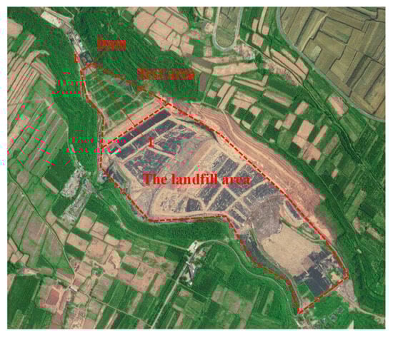
Figure 1.
Layout of the landfill.
The landfill employed a layered filling approach, with the thickness of each waste layer of approximately 10 m. Currently, the total waste thickness ranges from 70 to 80 m, consisting of eight layers (Layer 1 to Layer 8) from the base to the surface. To support vehicular operations while minimizing rainfall infiltration and odor emissions, intermediate loess cover layers (10–30 cm thick) were placed atop each waste layer (Figure 2). These intermediate barriers were constructed using locally sourced loess, which, after compaction, exhibits low permeability and restricts vertical leachate migration. This characteristic complicates the spatial distribution of leachate within the landfill, necessitating specialized monitoring and management strategies.
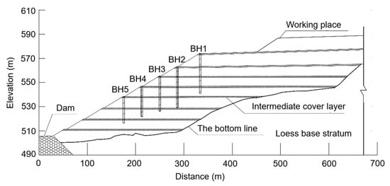
Figure 2.
Position of BH1 to BH5 on the cross-section of the landfill.
3. Methods
3.1. In Situ Testing of Multiple Leachate Levels
The multi-layer leachate level testing methodology is illustrated in Figure 3. A drilling operation utilizing a 91 mm diameter borehole was conducted, with periodic bit extraction and cleaning performed at 2 m intervals to maintain borehole integrity. Following drilling completion, thorough borehole cleaning preceded the installation of 130 mm diameter casing pipes. These thick-walled steel tubes, driven into position using a hammer, established an interference fit with the surrounding intermediate cover soils due to their larger diameter relative to the borehole. The significant permeability contrast between clay soils (intermediate covers) and waste materials enabled partial hydraulic isolation, effectively disrupting interlayer hydraulic connectivity. For targeted leachate level measurement in specific waste strata, casing pipe installation was terminated at 0.5–1 m above the corresponding intermediate cover layer. This configuration maintained the natural hydraulic regime while permitting accurate leachate level monitoring in discrete waste layers.
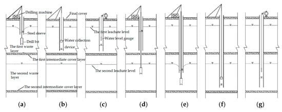
Figure 3.
Schematic of multi-layer leachate level measurement procedure: (a) initial waste layer drilling; (b) leachate extraction in first waste layer; (c) leachate level recovery monitoring; (d) intermediate cover layer drilling; (e) sleeve installation and second waste layer drilling; (f) leachate extraction in second waste layer; and (g) leachate level monitoring of the second waste layer.
During the interval of casing pipe installation, downward migration of leachate from upper waste layers through the borehole resulted in accumulation within the casing. To mitigate this effect, a specialized water collection device was developed (Figure 4). The device comprised a polypropylene random copolymer (PPR) pipe section integrated with a bottom-mounted check valve. Operational through gravitational action, the system permitted leachate inflow during descent, while valve closure during extraction enabled complete fluid removal.
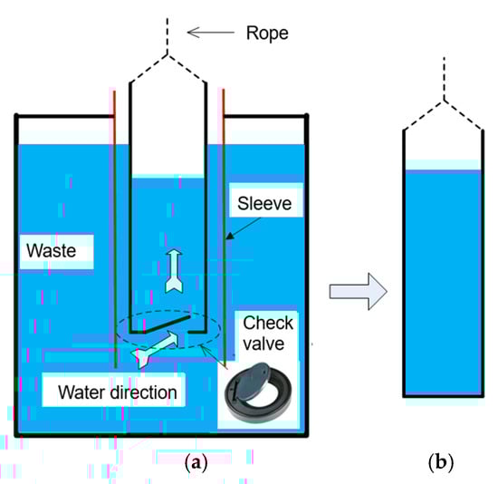
Figure 4.
Schematic of leachate collection device: (a) open-valve configuration during descent; (b) closed-valve state during extraction.
Following leachate extraction, the recovery phase was initiated to determine the equilibrium leachate level in each waste stratum. The recovery process involved gradual inflow of leachate from the undisturbed waste matrix into the casing pipe through the open bottom section. Monitoring was conducted at 2–4 h intervals using a calibrated water level probe, with measurements continuing until stabilization criteria were met (<5 mm variation over 4 h). The stabilized water level elevation was recorded as the representative leachate level for the specific waste layer was tested. Following the field investigations, all boreholes were carefully backfilled with native loess to maintain the landfill’s structural integrity and eliminate potential environmental disturbances.
The materials mentioned above are not commercial materials.
3.2. Numerical Simulation
Hydraulic conductivity is a critical parameter for understanding the flow behavior of leachate within the landfill. The hydraulic conductivities of various waste layers were determined through back analysis of leachate level recovery data. The numerical simulation was based on several fundamental assumptions: homogeneous and isotropic permeability within each waste layer, unsaturated flow conditions governing leachate movement, and axisymmetric flow geometry around the monitoring borehole. A representative case study was developed for the first waste layer of BH2 using the software SEEP/W(v. 4.0) (Figure 5). The computational domain featured a waste layer with dimensions of 9.4 m height × 20 m width, incorporating a casing pipe penetration depth of 7.0 m. Initial hydraulic conditions were specified with the leachate level inside the casing at 6.6 m below surface and outside at 4.76 m below surface, serving as initial pressure head boundaries in the simulation. The unsaturated flow regime was characterized using the soil–water characteristic curve reported by Zhang et al. [5]. The finite element discretization employed 4878 rectangular elements, providing sufficient resolution for precise pressure head calculations. Parameter optimization was achieved through an iterative calibration process that minimized the discrepancy between simulated and observed recovery curves. The validated modeling methodology was subsequently extended to analyze the second and third waste layers, with appropriate adjustments made for layer-specific thicknesses and initial leachate levels to maintain consistency throughout the analysis.
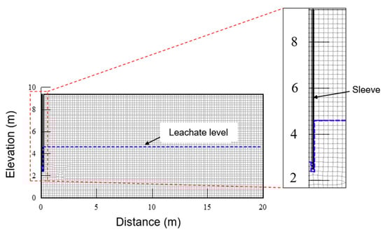
Figure 5.
Axisymmetric finite element model for leachate level recovery simulation in BH2.
A comprehensive numerical investigation was conducted to elucidate the formation mechanism of multi-layer leachate levels, employing the hydraulic conductivity values derived from previous back analysis. The parameters adopted in the numerical simulation, including the vertical spacing of intermediate cover layers, dimensions of drainage trenches, and their horizontal spacing, were all based on the actual design specifications of this landfill. The developed numerical model (Figure 6) represented the landfill’s stratified configuration, comprising three distinct 10 m waste layers (deep, middle, and shallow) characterized by their respective degradation stages and hydraulic properties. The model incorporated critical engineering components including a toe earth dam, 1 m composite bottom liner system, and 0.3 m intermediate silty clay covers with a saturated hydraulic conductivity of 1 × 10⁻⁶ cm/s. To simulate actual drainage conditions, the model integrated horizontal drainage trenches (1 m × 1 m) spaced at 100 m intervals along each waste layer base, implementing free drainage boundary conditions. The simulation process adopted a sequential approach that replicated the landfill’s historical filling sequence. During the initial 5-year phase, only the bottom waste layer was activated, assigned with shallow waste properties, while upper layers remained nullified. The subsequent intermediate phase (5–10 years) introduced the middle waste layer and corresponding cover system, with material properties adjusted to reflect waste aging processes. The final simulation stage (10–15 years) incorporated all waste layers with appropriate hydraulic parameters, enabling a complete assessment of the landfill’s hydraulic behavior. Key boundary conditions were established based on extensive field measurements and experimental data. The model implemented a surface infiltration rate of 0.007 m/d, derived from local precipitation patterns and leachate generation data reported by Zhan et al. [9]. Initial waste moisture content was set at 60%, consistent with on-site measurements ranging from 50 to 70%. The unsaturated flow characteristics were defined using established soil-water characteristic curves from Zhang et al. [5]. For comparative analysis, a hypothetical homogeneous condition (without intermediate cover layers) was simulated. This can be easily achieved in the numerical model by assigning parameters of waste to the cover elements. This approach facilitated the evaluation of intermediate cover layer effects on leachate distribution patterns.
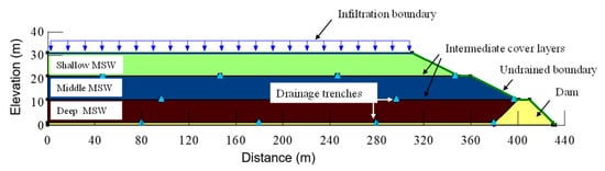
Figure 6.
Numerical model for multi-layer leachate level analysis.
4. Results and Discussion
4.1. In Situ Characterization of Multi-Layer Leachate Levels
The central boreholes (BH2, BH3, and BH4) provided representative data for characterizing the multi-layer leachate distribution within the landfill. BH2 exhibited characteristic hydraulic responses across four depth intervals (Figure 7a), beginning with the first intermediate cover layer at 9.3–9.5 m depth. Initial drilling to 7.5 m produced a leachate level measurement of 6.6 m below ground surface (bgs), followed by a recovery profile showing rapid initial rise (to 5.08 m bgs within 2 h) and subsequent stabilization at 4.76 m bgs after 24 h. Similar patterns emerged at greater depths, though with increasing complexity: the second layer (18.0–18.3 m) demonstrated substantial recovery from 16 m to 10.35 m bgs, while the third layer (30.1–30.2 m) showed more limited recovery from 27.88 m to 27.62 m bgs. The most notable hydraulic behavior occurred in the fourth layer, where leachate levels rose from 31.5 m to 26.2 m bgs—surpassing the intermediate cover elevation by 3.9 m. This anomalous response suggests the development of confined conditions within the waste mass, corroborating previous observations of leachate ejection phenomena by Zhan et al. [12]. The vertical heterogeneity in recovery patterns highlights the complex interplay between waste composition, cover system effectiveness, and depth-dependent hydraulic processes.
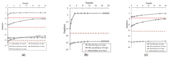
Figure 7.
Leachate level recovery curve of (a) BH2, (b) BH3, and (c) BH4.
Measurements demonstrated that intermediate loess cover layers significantly alter leachate transport dynamics, creating discrete perched zones that impede vertical migration. Each cover layer maintained a corresponding perched water table, consistent with findings by Qi et al. [13] and Zhang et al. [14]. Interestingly, while waste age increased systematically with depth, no direct correlation emerged between aging and leachate levels. Instead, drainage capacity variations primarily governed perched water head differences across layers. The data revealed substantial layer-to-layer variability in saturation conditions. The third waste layer showed the lowest leachate level (18% of layer thickness), followed by the first layer (56%), while the second and fourth layers approached near saturation. All layers shared common recovery kinetics, exhibiting recovery rates over time and reaching stabilization within 24 h.
The findings underscore the critical role of intermediate cover systems in creating complex, multi-layer saturation regimes within modern landfills. The development of perched leachate zones has important implications for slope stability assessments and leachate management strategies, particularly in deep landfill sections where confined conditions may develop. These results emphasize the need for comprehensive monitoring programs that account for vertical heterogeneity in landfill hydraulic behavior.
The investigation of BH3 revealed anomalous conditions at the expected 10 m depth intermediate cover location, where no distinct hydraulic barrier was detected (Figure 7b). This absence may result from either reduced cover thickness or material mixing during leachate migration events. In contrast, the secondary intermediate cover at 17.9–18.2 m depth exhibited pronounced hydraulic behavior, with leachate levels rapidly recovering from 14.85 m to 8.4 m bgs within the initial hour due to substantial head differentials, ultimately stabilizing at 3.75 m bgs after 24 h. The complete saturation profile (78% of layer thickness) confirmed the compromised integrity of the upper cover system at this location. BH4 (Figure 7c) displayed more conventional multi-layer behavior, with primary and secondary intermediate covers identified at 7.3–7.4 m and 16.6–16.8 m depths, respectively. The upper layer demonstrated steady recovery from 6.62 m to 4.08 m bgs over 24 h, while the deeper layer progressed from 13.15 m to 7.82 m bgs during the same period, with a third stabilization level recorded at 23.65 m bgs.
Comprehensive data synthesis (Table 1, Figure 8) confirmed the fundamental role of intermediate covers in establishing discrete perched leachate zones while also revealing significant spatial heterogeneity in their hydraulic performance. Differential settlement patterns, particularly pronounced near the landfill center where overburden pressures exceeded 5 m of vertical displacement [15], created sloped interfaces that promoted localized leachate accumulation. The anisotropic nature of waste materials produced inconsistent perched zone development in deeper strata, evidenced by variable stabilized levels (24 m in BH3 versus distinct elevations in BH4/BH2). Slope surface inspections identified preferential flow paths between BH5-BH4 (Figure 9), where localized leakage corresponded precisely with perched leachate formations, demonstrating the complex coupling between waste settlement dynamics and fluid transport mechanisms. These observations highlight the critical importance of considering both vertical stratification and lateral variability when assessing landfill hydraulic behavior.

Table 1.
Summary of drilling and leachate level information.
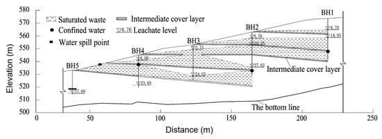
Figure 8.
The tested leachate distribution in the landfill.
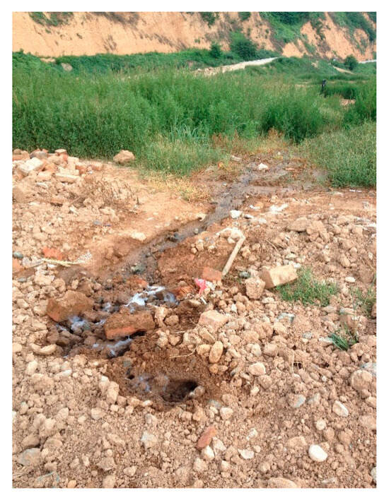
Figure 9.
Leachate leakage points.
4.2. Numerical Simulation Results
The back analysis successfully calibrated waste hydraulic conductivity through the iterative matching of simulated and measured leachate recovery data (Figure 10). Optimal parameterization yielded conductivity values (ks) spanning an order of magnitude (1 × 10⁻⁴ to 3.3 × 10⁻³ cm/s), consistent with established ranges for landfilled waste [16,17]. The first waste layer simulation achieved exceptional agreement (ks = 3.3 × 10⁻³ cm/s), accurately reproducing the rapid equilibration of the initial 1.84 m head difference to 5.08 m bgs within 2 h. Deeper strata exhibited progressively reduced conductivity, with the second layer requiring ks = 2 × 10⁻³ cm/s despite slight overestimation of recovery rates—a discrepancy potentially attributable to casing-induced waste matrix compaction during field testing. The third layer demonstrated optimal calibration at ks = 1 × 10⁻⁴ cm/s, precisely matching observed recovery behavior. This vertical conductivity gradient reflects expected waste heterogeneity, with decreasing values corresponding to increasing overburden pressures and material decomposition states at greater depths.
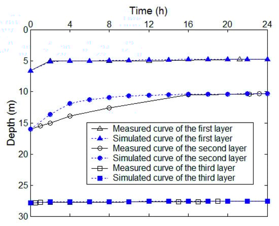
Figure 10.
Comparison of simulated and measured leachate level recovery in BH2.
Figure 11a illustrates the pronounced development of perched leachate zones within the landfill containing intermediate cover layers. The low-permeability characteristics of these intermediate layers significantly impeded vertical leachate migration, resulting in discrete perched leachate accumulations above each cover layer. Under conditions of effective trench drainage, the leachate level in the bottom waste layer remained low, as the drainage trenches maintained leachate at their installation depth. The intermediate cover layers wholly prevented leachate infiltration from the upper layers to the bottom stratum. The upper waste layers exhibit funnel-shaped leachate distributions with gradually increasing levels away from drainage trenches. Comparative analysis (Figure 11b) showed that landfill configurations without intermediate covers maintain a uniform leachate level near 0.9 m (trench installation depth) as leachate discharges primarily through the drainage system, effectively preventing the formation of multi-layer perched zones. These findings highlight the critical role of intermediate cover layers in creating complex, stratified leachate distributions that differ fundamentally from the relatively uniform hydraulic regimes observed in conventional landfill designs. The numerical results further indicate that, while trench drainage systems effectively control basal leachate levels in both configurations, their interaction with intermediate covers produces distinct multi-layer saturation patterns that significantly influence overall landfill hydraulics.
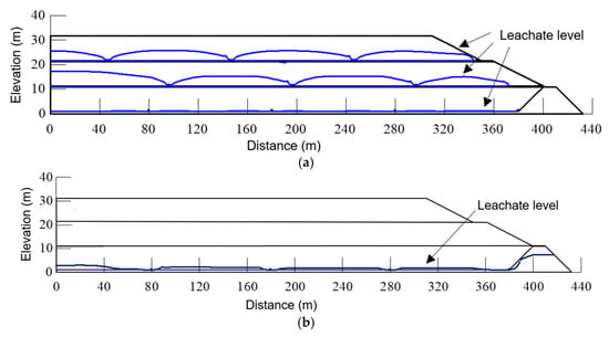
Figure 11.
Comparative leachate distribution under effective trench drainage conditions: (a) multi-layer system showing perched zones and funnel-shaped distributions, and (b) conventional landfill configuration maintaining uniform leachate level.
Figure 12 presents two characteristic leachate distribution patterns emerging under compromised drainage conditions. The conventional landfill configuration (without intermediate covers) develops a singular leachate mound typically positioned 2–3 m below the ground surface (Figure 12a), consistent with field measurements by Peng et al. [11] documenting elevated leachate levels (0–2 m depth) in a drainage-impaired landfill in Southern China. In contrast, systems incorporating intermediate covers exhibit multi-tiered saturation patterns, with distinct perched accumulations forming above each low-permeability barrier (Figure 12b). This stratified configuration leads to significantly elevated hydraulic heads at multiple depths, as evidenced by field data from Zhang et al. [5] reporting simultaneous leachate mounds at 10.7 m (primary) and 4.7 m (perched) depths in the Suzhou landfill. The numerical simulations demonstrate remarkable consistency with empirical observations, confirming two fundamental principles of landfill hydraulics: intermediate covers systematically induce perched leachate formation, and multiple cover layers create vertically stratified saturation regimes that substantially modify fluid distribution compared to conventional landfill designs.
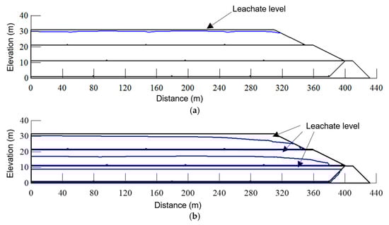
Figure 12.
Comparative leachate distribution patterns under impaired drainage conditions: (a) conventional landfill configuration showing single leachate mound development and (b) multi-layer system exhibiting stratified perched accumulations above intermediate covers.
5. Conclusions
This study elucidates the formation mechanisms of multi-layer leachate systems in modern landfills through integrated field investigations and numerical modeling. The developed in situ measurement methodology, employing controlled drilling termination, oversized casing installation, and systematic leachate recovery monitoring, provides a reliable approach for characterizing stratified leachate distributions. Field data confirm that intermediate loess cover layers function as effective hydraulic barriers, creating discrete perched zones with variable water heads (18–78% of layer thickness) depending on waste drainage characteristics and settlement-induced topographic variations. Back analysis-derived hydraulic conductivity values (1 × 10⁻⁴ to 3.3 × 10⁻³ cm/s) exhibit depth-dependent reduction patterns consistent with waste aging and compaction processes. Numerical simulations further reveal that, while effective horizontal drainage can reduce perched leachate elevations, the fundamental compartmentalization caused by intermediate covers persists, creating distinct hydraulic regimes that differ significantly from conventional landfill designs.
For improved landfill management, several practical measures should be considered. Enhanced monitoring systems should incorporate multi-layer leachate level measurement and inclinometers to track both perched zone development and differential settlement impacts, with periodic hydraulic conductivity profiling to assess system performance. Design optimizations could include evaluating permeable intermediate cover alternatives in high-settlement areas, implementing stepped drainage trench configurations. Operational strategies should prioritize leachate extraction from upper perched zones while adjusting pumping schedules according to the in situ distribution of leachate level, complemented by regular slope stability assessments that account for perched water effects. Future research should focus on the long-term performance evaluation of alternative cover materials, coupled with the mechanical–hydraulic modeling of waste-cover systems and the development of smart monitoring technologies for real-time perched zone detection. These integrated approaches will advance both the theoretical understanding and practical management of multi-layer leachate systems in modern landfill operations.
Author Contributions
Conceptualization, W.S. and J.L.; methodology, Y.Z. and J.L.; investigation, Y.L. and H.G.; writing—original draft preparation, W.S.; writing—review and editing, Y.Z. and J.L. All authors have read and agreed to the published version of the manuscript.
Funding
This research received no external funding.
Data Availability Statement
The datasets used and analyzed during the current study are available from the corresponding author upon reasonable request.
Conflicts of Interest
Authors Wei Shi, Yang Zhang, and Yifan Lin were employed by Xi’an Solid Waste Disposal Center. Author Han Gao was employed by the company CUCDE Environmental Technology Co., Ltd. The remaining authors declare that the research was conducted in the absence of any commercial or financial relationships that could be construed as a potential conflict of interest. The companies had no role in the design of the study; in the collection, analyses, or interpretation of data; in the writing of the manuscript, or in the decision to publish the results.
References
- Huang, M.H.; Zhang, Z.Y.; Zhu, B.; Zhang, J.H.; Xu, H. Effects of moisture content and landfill age on the shear strength properties of municipal solid waste in Xi’an China. Environ. Sci. Pollut. Res. 2023, 30, 65011–65025. [Google Scholar] [CrossRef] [PubMed]
- Zhang, W.J.; Yuan, S.S. Characterizing preferential flow in landfilled municipal solid waste. Waste Manag. 2019, 84, 20–28. [Google Scholar] [CrossRef] [PubMed]
- Lou, Y.F.; Zhang, Z.Y.; Li, T.; Zhang, Y.W.; Chen, W.J. Compressibility characteristics of municipal solid waste considering multiple factors. Environ. Sci. Pollut. Res. 2024, 31, 44401–44414. [Google Scholar] [CrossRef] [PubMed]
- Wang, C.H.; Zhang, Z.Y.; Ma, Z.H.; Zhang, Y.W.; Zhu, H.; Lu, B.K.; Chen, W.J. Degradation and stabilization degree of municipal solid waste: The case of two landfills in China. Sustainability 2025, 17, 307. [Google Scholar] [CrossRef]
- Zhang, W.J.; Zhang, G.G.; Chen, Y.M. Analyses on a high leachate mound in a landfill of municipal solid waste in China. Environ. Earth Sci. 2013, 70, 1747–1752. [Google Scholar] [CrossRef]
- Chen, Y.M.; Li, J.C.; Yang, C.B.; Zhu, B.; Zhan, L.T. Centrifuge modeling of municipal solid waste landfill failures induced by rising water levels. Can. Geotech. J. 2017, 54, 1739–1751. [Google Scholar] [CrossRef]
- Touze-Foltz, N.; Xie, H.J.; Stoltz, G. Performance issues of barrier systems for landfills: A review. Geotext. Geomembr. 2021, 49, 475–488. [Google Scholar] [CrossRef]
- Shu, S.; Li, Y.P.; Sun, Z.M.; Shi, J.Y. Effect of gas pressure on municipal solid waste landfill slope stability. Waste Manag. Res. 2022, 40, 323–330. [Google Scholar] [CrossRef] [PubMed]
- Zhan, L.T.; Xu, X.B.; Chen, Y.M.; Ma, X.F.; Lan, J.W. Dependence of gas collection efficiency on leachate level at wet municipal solid waste landfills and its improvement methods in China. J. Geotech. Geoenviron. Eng. 2015, 141, 04015002. [Google Scholar] [CrossRef]
- Hu, J.; Wu, X.W.; Ke, H.; Xu, X.B.; Lan, J.W.; Zhan, L.T. Application of electrical resistivity tomography to monitor the dewatering of vertical and horizontal wells in municipal solid waste landfills. Eng. Geol. 2019, 254, 1–12. [Google Scholar] [CrossRef]
- Peng, R.; Hou, Y.J.; Zhan, L.T.; Yao, Y.P. Back-Analyses of Landfill Instability Induced by High Water Level: Case Study of Shenzhen Landfill. Int. J. Environ. Res. Public Health 2016, 13, 126. [Google Scholar] [CrossRef] [PubMed]
- Zhan, L.T.; Zhan, X.J.; Lin, W.A. Field and laboratory investigation on geotechnical properties of sewage sludge disposed in a pit at Changan landfill, Chengdu, China. Eng. Geol. 2014, 170, 24–32. [Google Scholar] [CrossRef]
- Qi, G.X.; Yue, D.B.; Liu, J.G.; Li, R.; Shi, X.C.; He, L.; Guo, J.T.; Miao, H.M.; Nie, Y.F. Impact assessment of intermediate soil cover on landfill stabilization by characterizing landfilled municipal solid waste. J. Environ. Manag. 2013, 128, 259–265. [Google Scholar] [CrossRef] [PubMed]
- Zhang, P.Y.; Chai, J.R.; Cao, J.; Qin, Y.; Dang, M.R.; Wang, T.C. Analysis of the existence form of landfill leachate water level and its development pattern under the condition of considering internal source water: A case study. Environ. Sci. Pollut. Res. 2023, 30, 9820–9840. [Google Scholar] [CrossRef]
- Ren, Y.B.; Zhang, Z.Y.; Huang, M. A review on settlement models of municipal solid waste landfills. Waste Manag. 2022, 149, 79–95. [Google Scholar] [CrossRef] [PubMed]
- Xu, X.B.; Zhan, L.T.; Chen, Y.M.; Beaven, R.P. Intrinsic relative permeabilities of shredded municipal solid wastes from the Qizishan landfill China. Can. Geotech. J. 2014, 51, 1243–1252. [Google Scholar] [CrossRef]
- Zhang, C.S.; Meng, M.; Qin, R.; Hu, J.; Zhang, W.J.; Lan, J.W.; Chen, Y.M.; Ke, H. Bimodal water retention curves and segmented relative permeabilities of municipal solid waste. Can. Geotech. J. 2025, 62, 1–22. [Google Scholar] [CrossRef]
Disclaimer/Publisher’s Note: The statements, opinions and data contained in all publications are solely those of the individual author(s) and contributor(s) and not of MDPI and/or the editor(s). MDPI and/or the editor(s) disclaim responsibility for any injury to people or property resulting from any ideas, methods, instructions or products referred to in the content. |
© 2025 by the authors. Licensee MDPI, Basel, Switzerland. This article is an open access article distributed under the terms and conditions of the Creative Commons Attribution (CC BY) license (https://creativecommons.org/licenses/by/4.0/).