Abstract
This study numerically investigates the solid–liquid mixing characteristics in solid–liquid stirred tanks with solid volume fraction as high as 35%, focusing on the effect of impeller and baffle configurations on solid and liquid flow behaviors. Three stirred tanks with different capacities and impellers were analyzed to evaluate liquid flow field, solid suspension, and free surface profiles. It has demonstrated superior shear rate uniformity in the multi-impeller systems compared to the single-impeller, attributed to the enhanced fluid circulation. Multi-impeller systems can achieve near-complete off-bottom suspension, while the single-impeller configuration exhibited band-shaped particle accumulation above the impeller. Free surface vortices, significantly deeper in the 6 m3 multi-impeller tank due to high blade tip velocities, were mitigated through the integration of four circumferentially arranged triangular baffles. The existence of baffles can suppress surface turbulence, promote axial flow patterns, and eliminate particle accumulation at the tank bottom, improving shear rate and solid concentration homogeneity. These findings provide a beneficial guideline for the optimization of solid–liquid mixing efficiency the similar flow system or processes.
1. Introduction
Under high solids loading conditions (>20 vol%) [1,2], achieving effective particle suspension and uniform dispersion presents significant challenges. The hydrodynamic characteristics within stirred tanks fundamentally determine solid-phase suspension quality. Recent studies predominantly focus on baffled reactors [3,4,5], often neglecting the influence of free surface deformation on particle suspension dynamics.
Unbaffled stirred tanks demonstrate unique advantages in specific applications [6]. For instance, the presence of baffles enhances frictional interactions with crystal surfaces and suppresses crystal growth in crystallization reactors. Under constant agitation power, baffle-free agitated vessels demonstrate superior performance in facilitating mass transfer between liquid and particles [7,8]. The defining feature of unbaffled systems is intense vortex-dominated flow [9]. Centrifugal forces induce a pronounced vortex at the free liquid surface, which progressively deepens with increasing agitation speed. This vortex may extend toward impellers and even tank bottoms, triggering gas entrainment that forms gas–liquid mixtures [10,11]. Such phenomena severely compromise suspension homogeneity and operational stability. Systematic investigation of free-surface vortices is, therefore, essential for optimizing unbaffled solid–liquid suspension systems.
Solid-phase suspension mixing operations are widely employed in chemical processes [12]. In most solid–liquid suspension systems, particles can achieve complete suspension but often fail to distribute uniformly throughout the mixing tank. Non-uniform particle distribution adversely affects process outcomes in reactors, making understanding particle distribution patterns crucial for equipment design and process development [13]. In addition, some studies underscore flow pattern dominance in multiphase mixing [14,15]. This work establishes predictive models correlating flow fields with multiphase mixing performance.
Traditional experimental methods for determining solid-phase distribution in stirred tanks are time-consuming, labor-intensive, and costly. Computational Fluid Dynamics (CFD) provides an efficient numerical modeling approach to simulate and analyze fluid flow phenomena. Compared to conventional experimentation, CFD significantly reduces time and resource expenditures. In process development and equipment optimization, CFD enables visualization of solid–liquid mixing flows without physical experimentation, while providing more detailed fluid dynamics insights.
Two primary modeling approaches exist for CFD simulation of solid–liquid two-phase flows: the Euler–Euler (EE) method [16] and the Euler–Lagrange (EL) method [17]. In the EE approach, both phases are treated as interpenetrating continua. The mass and momentum conservation equations are solved on the same Eulerian grid. The EL method considers the solid phase as discrete particles, solving continuous-phase equations similar to single-phase flow while tracking dispersed particles through point-particle or parcel models. Compared to the EL method, the EE approach demonstrates superior accuracy for high-concentration solid–liquid two-phase systems.
Liu et al. [18] employed the Euler–Euler method with a modified Brucato drag model for coaxial anchor-Rushton impellers, revealing co-rotational mode enhances bottom turbulence but excessive Rushton speeds degrade uniformity. Mozaffari et al. [19] combined Euler–Euler and k−ε turbulence modeling to demonstrate Lightnin A100 impellers achieve 18–23% better homogeneity than A200/A310 variants, with particle properties critically influencing mixing. Ochieng et al. [20] integrated sliding-mesh CFD with LDV measurements, showing transient simulations improve small-particle (<100 μm) accuracy by 31% versus steady-state methods. Liu and Barigou [21] confirmed Eulerian multiphase models reliably predict velocity/concentration profiles across 5~40 wt% suspensions. Collectively, these works establish method-specific strengths: Euler–Euler for impeller optimization, transient CFD for fine particles, and multiphase models for industrial-scale concentrations.
This study develops a numerical model for solid–liquid mixing in energetic granule fabrication. Firstly, the impact of solid-phase particle addition on free surface morphology was investigated. Subsequent analyses quantified flow field characteristics, including velocity profiles, solid concentration distributions, and shear rate patterns. Finally, triangular baffles were designed to optimize mixing efficiency, which is the biggest innovation point that sets this article apart from previous works.
The paper is structured as follows: The Section 2 presents the flow system, numerical methodology and simulation schemes. The Section 3 analyze free surface evolution, velocity fields, suspension homogeneity, and shear dynamics. Then, the mixing enhancement effects of baffle are then systematically evaluated. Key findings are summarized in the Section 4.
2. Flow System and Simulation Method
2.1. Flow System
The schematic diagram of the flow system is depicted in Figure 1. Figure 1a shows a 1 m3 standard elliptical-head stirred tank equipped with four two-bladed pitched-blade impellers. Figure 1b,c depict identical 6 m3 elliptical-head stirred tanks with modified impeller configurations: Figure 1b retains four two-bladed pitched-blade impellers, while Figure 1c employs a single six-bladed pitched-blade impeller. All tanks are fitted with thermometers. Detailed geometric parameters are summarized in Table 1. Table 2 is the properties of air, water, and particle used in this work. The particles in our study are spherical and have uniform density. The surface tension is 0.073 N·m−1.
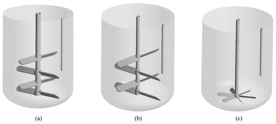
Figure 1.
Three-dimensional stirred tank configurations: (a) 1 m3 with multi-impellers, (b) 6 m3 with multi-impellers, (c) 6 m3 with single-impeller.

Table 1.
Geometric and operational parameters.

Table 2.
Physical properties of material.
2.2. Multiphase Flow Model and Governing Equations
In this study, the Eulerian–Eulerian model was used to characterize the gas–solid three-phase flow. Here, the gas phase and particle are the dispersed phase, whereas the liquid phase serves as the continuous phase. Each phase adheres to its own continuity and momentum equations, which are presented as follows [22]
where the subscript i denotes the gas, liquid, and solid phases, respectively. is the density, and is the velocity. is the volume fraction. represent the net forces acting on the liquid and solid phases, respectively. The main forces include components of gravity, pressure gradients, viscosity terms, and other interfacial forces such as drag, lift, and buoyancy [23].
Computational and experimental studies have quantitatively established that the other force exhibit magnitudes smaller than drag and gravity under typical suspension conditions, thereby negligibly influencing phase distribution characteristics [24,25,26]. Consequently, the interphase momentum transfer in the current study is confined to the dominant drag force and gravity. The drag force is formulated as:
where is the particle diameter, is the drag coefficient. Considering the high solid holdup (more than 20%) in the simulation in this study, the Gidaspow drag model suitable for high solid holdup system is used to calculate the drag coefficient [27]:
The hydrodynamic behavior in agitated vessels typically exhibits complex turbulence characteristics. To resolve this challenge, the standard k−ε model [28] was employed in this study. This turbulence closure scheme presumes fully developed turbulence while neglecting molecular viscous effects and phase interactions between dispersed particles and the liquid medium. The governing equation for turbulent kinetic energy transport is expressed as follows:
where
The empirical constants in the model are: = 1.44, = 1.92, = 0.09, = 1.0, and = 1.3.
2.3. System Investigated and Boundary Conditions
In this study, the CFD simulations employed the flow system described in the preceding section. As demonstrated in Figure 2, polyhedral cells were generated using the commercial software Fluent Meshing 2022 R1, which were adopted due to their significant advantages over tetrahedral cells in computational efficiency and accuracy. The number of polyhedral cells is listed in Table 3.
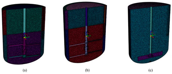
Figure 2.
Mesh of stirred tank configurations: (a) 1 m3 multi-impeller, (b) 6 m3 multi-impeller, (c) 6 m3 single-impeller.

Table 3.
Mesh parameters.
The Ansys Fluent 2022 R1 software was employed with a pressure-based solver. The gravitational acceleration was 9.81 m/s2 in negative z-direction. The simulation of rotor motion employed the multiple reference frame technique. Coupling of pressure and velocity was achieved through the SIMPLE algorithm. The second-order implicit scheme was used for time advancement. All the wall boundaries were maintained no-slip. Convergence at each time step was achieved when the normalized residuals of the continuity, mass fraction, and velocities were lower than 10−4.
Grid independence was rigorously validated. As illustrated in Figure 3, taking the solid concentration distribution along the vertical line in a 6 m3 multi-layered impeller stirred tank as an example, significant discrepancies in simulation results were observed when the grid number exceeded 1.03 million. To balance computational efficiency and simulation accuracy, all subsequent simulations on 6 m3 multi-layered impeller stirred tank were performed using the model with 1.03 million grid cells.
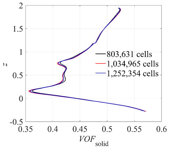
Figure 3.
Solid volume fraction with different cell number at radial coordinates = 0.1 m and angle coordinates = 45°.
3. Results and Discussion
3.1. Flow Field
Figure 3 is the non-dimensional velocity distribution scaled by impeller tip speed in the gas–liquid–solid system within the stirred tank. The translucent iso-surface, where gas volume fraction is 0.5, demarcates the liquid surface inside the tank. Figure 4a,b demonstrate similar flow patterns in both 1 m3 and 6 m3 multi-impeller systems. Localized circulation patterns form near each impeller tip, while sequential impeller interactions establish axial circulation loops across the tank. Figure 4c reveals axisymmetric axial circulation under single-impeller down-pumping operation. Due to the low installation height of the single impeller, its influence diminishes near the free surface, resulting in reduced velocities in the upper region.
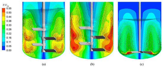
Figure 4.
Axial slice of flow fields in stirred tanks: (a) 1 m3 with multi-impeller, (b) 6 m3 with multi-impeller, (c) 6 m3 with single-impeller.
Figure 5 illustrates the shear rate distribution within three stirred tanks. Figure 5a,b demonstrate the shear rate distributions in 1 m3 and 6 m3 multi-impeller systems, revealing uniform patterns with peak values localized at impeller tips and tank walls. In contrast, Figure 5c shows significant spatial heterogeneity in the 6 m3 single-impeller system, where high shear zones concentrate near the impeller and walls, while the upper-middle regions exhibit markedly lower shear rates. This contrast highlights the advantage of multi-impeller configuration in maintaining consistent shear fields across scaled systems.
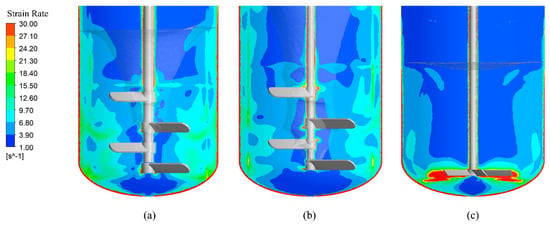
Figure 5.
Axial slice of shear rate distribution in stirred tanks: (a) 1 m3 with multi-impeller, (b) 6 m3 with multi-impeller, (c) 6 m3 with single-impeller.
To quantitatively evaluate the uniformity of shear rate distribution, the coefficient of variation for shear rates within the solid–liquid mixture can be calculated as:
where denotes the spatially averaged shear rate, and is the volume filled with solid and liquid. The smaller the , the more uniform the shear rate distribution.
The calculated values for the 1 m3 multi-impeller, 6 m3 multi-impeller, and 6 m3 single-impeller stirred tanks were 0.98, 2.59, and 3.13, respectively. These results quantitatively demonstrate that the multi-impeller system achieves superior shear rate uniformity compared to the single-impeller design. Furthermore, the attenuation of surface vortices, evident from the liquid surface morphology changes in Figure 5a,b, correlates with enhanced homogeneity in shear rate distribution.
3.2. Solid–Liquid Suspension
Figure 6a,b illustrate solid volume fraction distributions in 1 m3 and 6 m3 multi-impeller systems. Both configurations achieve generally uniform solid dispersion under operational conditions, with localized high-concentration zones confined below the bottom impeller. Figure 6c reveals distinct behavior in the 6 m3 single-impeller system: solids accumulate within the upper recirculation zone under down-pumping operation, forming an annular banded agglomeration. Centrifugal forces drive a radial distribution pattern with lower solid fractions centrally and higher concentrations near the sidewalls. Furthermore, the liquid surface and axial center regions exhibit negligible solid presence.
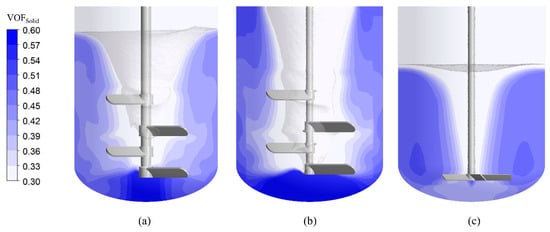
Figure 6.
Axial slice of solid volume fraction distribution in stirred tanks: (a) 1 m3 with multi-impeller, (b) 6 m3 with multi-impeller, (c) 6 m3 with single-impeller. The solid-filled phase (VOFSolid ≥ 0.5) is shown in blue.
In addition, in both 1 m3 and 6 m3 multi-impeller stirred tanks, only a minor fraction of mechanical energy contributes to the particle dispersion and solid suspension under vortex-dominated flow conditions, with most energy dissipated through circumferential rotation of solid and liquid. Blue regions represent liquid phase distribution, while orange zones (solid volume fraction ≥ 0.5) indicate particle accumulation areas. Quantitative analysis revealed that accumulation zones occupy 0.0189 m3 (1.90% of total solid–liquid volume) in the 1 m3 system, whereas the 6 m3 system exhibits a significant increase to 0.265 m3 (5.36% of total volume), showing a 64.6% rise in solid accumulation compared to the smaller-scale system.
Figure 6c illustrates solid-phase accumulation in the 6 m3 single-impeller system. Compared to the multi-impeller configuration at identical rotational speeds, the single impeller features lower positioning, smaller diameter, and reduced tip speed, resulting in weaker vortex formation. The six-blade design enhances bottom solids entrainment, achieving 38% higher scouring efficiency than the dual-blade multi-impeller system.
Flow analysis reveals dominant circumferential liquid motion with a localized upper circulation zone. Limited pumping capacity restricts circulation to the middle cylindrical section. Solids entrained from the bottom accumulate in this upper circulation zone, forming an annular agglomeration band. Quantitative assessment shows this accumulation occupies 0.265 m3, occupying 21.36% of total volume.
Interestingly, we also observed that a more uniform shear rate distribution corresponds to a smaller volume of the solid accumulation region. This indicates a positive correlation between flow field uniformity and solid-phase suspension efficiency.
3.3. Free Surface
As shown in Figure 7a,b, scale-up of multi-impeller systems by simultaneously increasing impeller diameter and tip speed (Vtip), can intensify the vortex formation. This results in a deeper penetration of the inverted conical liquid surface toward the bottom impeller, with vortex depth reaching 40% of the liquid height in the 6 m3 system compared to 22% in the 1 m3 configuration.
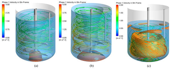
Figure 7.
Streamline of liquid phase in stirred tanks: (a) 1 m3 with multi-impeller, (b) 6 m3 with multi-impeller, (c) 6 m3 with single-impeller. Solid accumulation zones in orange, and liquid phase regions in blue.
Under identical operating conditions, comparison with the gas–liquid two-phase system in Figure 8a,b reveals a significantly higher liquid level rise (18.8% increase) in the gas–liquid–solid three-phase system. Quantitative analysis attributes this to the elevated average density of the three-phase mixture—a 5.3% density increase occurs at 35% solid loading compared to the liquid-only system. The denser mixture amplifies centrifugal forces during circumferential flow, intensifying vortex formation and associated liquid surface deformation.
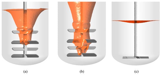
Figure 8.
Free surface profiles in stirred tanks with solid phase: (a) 1 m3 with multi-impeller, (b) 6 m3 with multi-impeller, (c) 6 m3 with single-impeller (the iso-surface of gas volume fraction in 0.5 is regarded as free surface).
3.4. Effect of Baffle on Solid–Liquid Mixing
The comparative analysis demonstrates that multi-impeller configurations outperform single-impeller systems in achieving uniform solid–liquid suspension and shear rate distribution. However, vortex-induced challenges limit their industrial scalability. To address this, four circumferentially arranged triangular baffles were designed to suppress vortex formation.
As shown in Figure 9, the baffles induce distinct axial circulation patterns near the liquid surface while eliminating vortical flow. This modification enhances velocity field uniformity throughout the tank. Figure 10 further reveals improved shear rate homogeneity in the liquid phase under baffled conditions. The coefficient of variation is 1.98, which is better than that in the 6 m3 stirred tank with multi-impeller but no baffles.
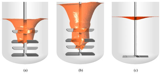
Figure 9.
Free surface in stirred tanks without solid phase: (a) 1 m3 with multi-impeller, (b) 6 m3 with multi-impeller, (c) 6 m3 with single-impeller. The iso-surface of gas volume fraction in 0.5 is regarded as free surface.
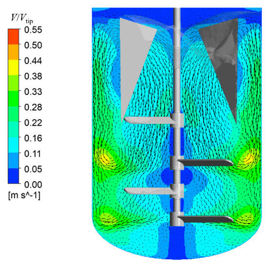
Figure 10.
Axial slice of flow fields in 6 m3 stirred tank with triangular baffles.
Comparative analysis of Figure 11 and Figure 5b demonstrates that baffle installation enhances solid-phase distribution uniformity while eliminating particle accumulation in the bottom head. Figure 12 demonstrates the absence of solid accumulation zones (solid volume fraction ≥ 0.5), confirming optimized off-bottom suspension and enhanced distribution uniformity. In the gas–liquid–solid system under multi-impeller down-pumping operation, baffle implementation eliminates vortex formation. In Figure 13, flow analysis reveals circumferential liquid motion driven by the bottom impeller, with fluid near baffles redirected into axial circulation.
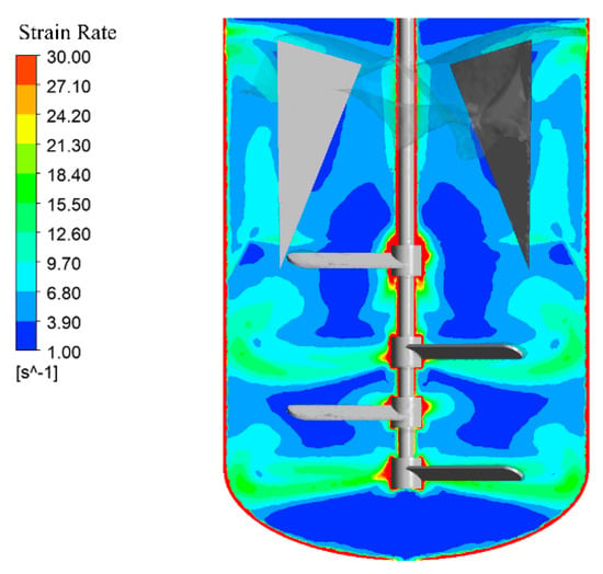
Figure 11.
Axial slice of shear rate distribution in 6 m3 stirred tank with triangular baffles.
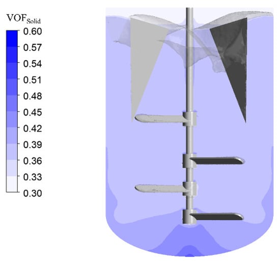
Figure 12.
Axial slice of solid-phase volume fraction distribution in 6 m3 stirred tank with triangular baffles. The solid-filled phase (VOFSolid ≥ 0.5) is shown in blue.
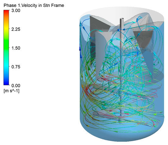
Figure 13.
Streamline of Liquid phase in 6 m3 stirred tanks with triangular baffles. Liquid phase regions in blue.
4. Conclusions
In this study, the Euler–Euler model was employed to numerically investigate high solid-loading multiphase mixing processes in stirred tanks with varying impeller types and scales. Additionally, triangular baffles were designed based on flow field results under baffle-free conditions to optimize the uniformity of shear rate and solid concentration distributions in the 6 m3 multi-impeller system.
Firstly, flow fields in the 1 m3 multi-impeller, 6 m3 multi-impeller, and 6 m3 single-impeller systems were compared. Results revealed pronounced swirling phenomena in both 1 m3 and 6 m3 multi-impeller tanks. At identical rotational speeds, the 6 m3 multi-impeller system exhibited higher blade tip velocities, leading to more severe swirling compared to the 1 m3 system. In the 6 m3 single-impeller tank, the impeller’s lower positioning localized high-velocity zones near the tank bottom. Qualitative and quantitative analyses demonstrated superior shear rate uniformity in multi-impeller systems.
Secondly, solid–liquid suspension behaviors were evaluated. Near-complete off-bottom suspension was achieved in both 1 m3 and 6 m3 multi-impeller tanks, with minor particle accumulation beneath impellers. In contrast, the 6 m3 single-impeller system showed band-shaped particle aggregation above the impeller.
Thirdly, free surface morphologies were analyzed. Surface vortices were observed in both 1 m3 and 6 m3 multi-impeller systems. The 6 m3 multi-impeller tank exhibited deeper vortices due to higher blade tip velocities at equivalent rotational speeds. Minimal surface vortices occurred in the 6 m3 single-impeller system, attributed to the basal positioning of the impeller and weaker axial pumping capacity.
Finally, four circumferentially arranged triangular baffles were integrated into the 6 m3 multi-impeller tank. These baffles suppressed surface vortex formation and enhanced axial circulation between the top impeller and liquid surface. Post-modification, shear rate and solid concentration distributions showed improved uniformity, with complete elimination of particle accumulation at the tank bottom.
Building on the current findings, future research will address key limitations and expand practical applications. Scale-up implications will be quantified through systematic geometric and dynamic similarity studies to bridge lab-scale results with industrial reactors. Energy-saving potential will be rigorously evaluated by correlating impeller-baffle configurations with power consumption metrics, enabling optimization of operational efficiency. Advanced baffle geometries (e.g., helical or perforated designs) will be explored to enhance flow homogeneity while minimizing dead zones. Furthermore, the framework will be extended to non-Newtonian systems through experimental validation of shear-thinning/thickening suspensions and development of modified turbulence closure models. These efforts will establish predictive scaling correlations while advancing sustainable mixing technology for complex multiphase processes in chemical, pharmaceutical, and wastewater treatment industries.
Author Contributions
Conceptualization, S.J. and Y.Z.; Methodology, S.J., X.Z. and Y.C.; Investigation, S.J., W.T. and C.C.; Writing—Original draft preparation, S.J.; Writing—review and editing, Y.Z. and J.W. All authors have read and agreed to the published version of the manuscript.
Funding
This research received no external funding.
Data Availability Statement
The original contributions presented in this study are included in the article. Further inquiries can be directed to the corresponding authors.
Conflicts of Interest
Authors Shengkun Jiang, Yuanyuan Zhao, Xin Zhao and Yu Chi were employed by the China Wuzhou Engineering Group Corporation LTD. Authors Chunlin Chen and Wenwen Tu were employed by the Luzhou North Chemical Industries Co., Ltd. The remaining author declares that the research was conducted in the absence of any commercial or financial relationships that could be construed as a potential conflict of interest.
References
- Xu, Z.; Jin, Z.; Liu, B.; Bengt, S. Experimental Investigation on Solid Suspension Performance of Coaxial Mixer in Viscous and High Solid Loading Systems. Chem. Eng. Sci. 2019, 208, 115144. [Google Scholar] [CrossRef]
- Wu, J.; Zhu, Y.G.; Pullum, L. Suspension of High Concentration Slurry. AIChE J. 2002, 48, 1349–1352. [Google Scholar] [CrossRef]
- Ayranci, I.; Kresta, S.M. Critical Analysis of Zwietering Correlation for Solids Suspension in Stirred Tanks. Chem. Eng. Res. Des. 2014, 92, 413–422. [Google Scholar] [CrossRef]
- Zwietering, T.N. Suspending of Solid Particles in Liquid by Agitators. Chem. Eng. Sci. 1958, 8, 244–253. [Google Scholar] [CrossRef]
- Narayanan, S.; Bhatia, V.K.; Guha, D.K.; Rao, M.N. Suspension of Solids by Mechanical Agitation. Chem. Eng. Sci. 1969, 24, 223–230. [Google Scholar] [CrossRef]
- Švec, O.; Skoček, J.; Stang, H.; Geiker, M.R.; Roussel, N. Free Surface Flow of a Suspension of Rigid Particles in a Non−Newtonian Fluid: A Lattice Boltzmann Approach. J. Non−Newton. Fluid Mech. 2012, 179–180, 32–42. [Google Scholar] [CrossRef]
- Sbrizzai, F.; Lavezzo, V.; Verzicco, R.; Campolo, M.; Soldati, A. Direct Numerical Simulation of Turbulent Particle Dispersion in an Unbaffled Stirred−Tank Reactor. Chem. Eng. Sci. 2006, 61, 2843–2851. [Google Scholar] [CrossRef]
- Freudig, B.; Hogekamp, S.; Schubert, H. Dispersion of Powders in Liquids in a Stirred Vessel. Chem. Eng. Process. Process Intensif. 1999, 38, 525–532. [Google Scholar] [CrossRef]
- Busciglio, A.; Scargiali, F.; Grisafi, F.; Brucato, A. Oscillation Dynamics of Free Vortex Surface in Uncovered Unbaffled Stirred Vessels. Chem. Eng. J. 2016, 285, 477–486. [Google Scholar] [CrossRef]
- Busciglio, A.; Caputo, G.; Scargiali, F. Free−Surface Shape in Unbaffled Stirred Vessels: Experimental Study via Digital Image Analysis. Chem. Eng. Sci. 2013, 104, 868–880. [Google Scholar] [CrossRef]
- Scargiali, F.; Busciglio, A.; Grisafi, F.; Brucato, A. Free Surface Oxygen Transfer in Large Aspect Ratio Unbaffled Bio−Reactors, with or Without Draft−Tube. Biochem. Eng. J. 2015, 100, 16–22. [Google Scholar] [CrossRef][Green Version]
- Yang, S.; Li, X.; Yang, C.; Ma, B.; Mao, Z.-S. Computational Fluid Dynamics Simulation and Experimental Measurement of Gas and Solid Holdup Distributions in a Gas–Liquid–Solid Stirred Reactor. Ind. Eng. Chem. Res. 2016, 55, 3276–3286. [Google Scholar] [CrossRef]
- Micale, G.; Carrara, V.; Grisafi, F.; Brucato, A. Solids Suspension in Three−Phase Stirred Tanks. Chem. Eng. Res. Des. 2000, 78, 319–326. [Google Scholar] [CrossRef]
- Kovalev, A.; Yagodnitsyna, A.; Bilsky, A. Plug Flow of Immiscible Liquids with Low Viscosity Ratio in Serpentine Microchannels. Chem. Eng. J. 2021, 417, 127933. [Google Scholar] [CrossRef]
- Der, O.; Bertola, V. An Experimental Investigation of Oil−Water Flow in a Serpentine Channel. Int. J. Multiph. Flow 2020, 129, 103327. [Google Scholar] [CrossRef]
- Guha, D.; Ramachandran, P.A.; Dudukovic, M.P.; Derksen, J.J. Evaluation of large Eddy simulation and Euler−Euler CFD models for solids flow dynamics in a stirred tank reactor. AIChE J. 2008, 54, 766–778. [Google Scholar] [CrossRef]
- Sungkorn, R.; Derksen, J.J.; Khinast, J.G. Euler–Lagrange Modeling of a Gas–Liquid Stirred Reactor with Consideration of Bubble Breakage and Coalescence. AIChE J. 2012, 58, 1356–1370. [Google Scholar] [CrossRef]
- Liu, B.; Xu, Z.; Xiao, Q.; Huang, B. Numerical Study on Solid Suspension Characteristics of a Coaxial Mixer in Viscous Systems. Chin. J. Chem. Eng. 2019, 27, 2325. [Google Scholar] [CrossRef]
- Hosseini, S.; Patel, D.; Ein−Mozaffari, F.; Mehrvar, M. Study of Solid−Liquid Mixing in Agitated Tanks Through Computational Fluid Dynamics Modeling. Ind. Eng. Chem. Res. 2010, 49, 4426–4435. [Google Scholar] [CrossRef]
- Ochieng, A.; Onyango, M.S.; Kiriamiti, K.H. CFD Simulation and Experimental Measurement of Nickel Solids Concentration Distribution in a Stirred Tank. J. South. Afr. Inst. Min. Metall. 2010, 110, 213–218. [Google Scholar]
- Liu, L.; Barigou, M. Experimentally Validated Computational Fluid Dynamics Simulations of Multicomponent Hydrodynamics and Phase Distribution in Agitated High Solid Fraction Binary Suspensions. Ind. Eng. Chem. Res. 2014, 53, 895–908. [Google Scholar] [CrossRef]
- Pukkella, A.K.; Vysyaraju, R.; Tammishetti, V.; Rai, B.; Subramanian, S. Improved Mixing of Solid Suspensions in Stirred Tanks with Interface Baffles: CFD Simulation and Experimental Validation. Chem. Eng. J. 2019, 358, 621–633. [Google Scholar] [CrossRef]
- Tamburini, A.; Cipollina, A.; Micale, G.; Brucato, A.; Ciofalo, M. CFD Simulations of Dense Solid–Liquid Suspensions in Baffled Stirred Tanks: Prediction of Suspension Curves. Chem. Eng. J. 2011, 178, 324–341. [Google Scholar] [CrossRef]
- Kasat, G.R.; Khopkar, A.R.; Ranade, V.V.; Pandit, A.B. CFD Simulation of Liquid−Phase Mixing in Solid–Liquid Stirred Reactor. Chem. Eng. Sci. 2008, 63, 3877–3885. [Google Scholar] [CrossRef]
- Altway, A.; Setyawan, H.; Margono; Winardi, S. Effect of Particle Size on Simulation of Three−Dimensional Solid Dispersion in Stirred Tank. Chem. Eng. Res. Des. 2001, 79, 1011–1016. [Google Scholar] [CrossRef]
- Shao, T.; Hu, Y.; Wang, W.; Jin, Y.; Cheng, Y. Simulation of Solid Suspension in a Stirred Tank Using CFD−DEM Coupled Approach. Chin. J. Chem. Eng. 2013, 21, 1069–1081. [Google Scholar] [CrossRef]
- Liu, L.; Barigou, M. Numerical Modelling of Velocity Field and Phase Distribution in Dense Monodisperse Solid–Liquid Suspensions Under Different Regimes of Agitation: CFD and PEPT Experiments. Chem. Eng. Sci. 2013, 101, 837–850. [Google Scholar] [CrossRef]
- Takahashi, K.; Fujita, H.; Yokota, T. Effect of Size of Spherical Particle on Complete Suspension Speed in Agitated Vessels of Different Scale. J. Chem. Eng. Jpn. 1993, 26, 98–100. [Google Scholar] [CrossRef]
Disclaimer/Publisher’s Note: The statements, opinions and data contained in all publications are solely those of the individual author(s) and contributor(s) and not of MDPI and/or the editor(s). MDPI and/or the editor(s) disclaim responsibility for any injury to people or property resulting from any ideas, methods, instructions or products referred to in the content. |
© 2025 by the authors. Licensee MDPI, Basel, Switzerland. This article is an open access article distributed under the terms and conditions of the Creative Commons Attribution (CC BY) license (https://creativecommons.org/licenses/by/4.0/).