Abstract
The low separation efficiency of conventional cyclone separators for sub-10 μm particles remains a critical challenge in Na2S production processes. Previous optimization attempts have failed to reconcile economic feasibility with effective fine particle capture requirements. To address this industrial bottleneck, we propose an innovative secondary separation cyclone design tailored for next-generation Na2S manufacturing systems. Our methodology synergizes computational fluid dynamics (CFD) simulations with experimental validation, achieving cost-effective development while ensuring numerical model reliability. Comparative analyses reveal significant improvements: under varying gas velocities, the novel design demonstrates 5.67–9.77% and 7.03–10.14% enhancements in 1–10 μm particle collection efficiency compared to standard and volute-type cyclones, respectively. Mechanistic investigations through flow field characterization elucidate the relationship between vortex dynamics and separation performance. This work provides a structurally optimized cyclone configuration with industrial applicability, as well as a validated hybrid experimental–computational framework that could inform solutions for fine particle separation across chemical processing industries.
1. Introduction
Sodium sulfide (Na2S) serves as a common reducing agent and precipitating agent that is widely employed across various industries, including dyes, leather, paper, textiles, and pharmaceuticals [1,2]. Sodium sulfide (Na2S) exists primarily in two distinct forms: industrial-grade sodium sulfide with high water content (Na2S·9H2O), typically exhibiting a purity exceeding 60%, and anhydrous sodium sulfide with significantly higher purity levels, often surpassing 90%. The anhydrous form, owing to its superior purity, finds extensive applications in critical industrial processes, such as polyphenylene sulfide (PPS) synthesis, vulcanized rubber manufacturing, and pharmaceutical production. The production of high-purity sodium sulfide involves complex manufacturing processes and is constrained by raw material availability, resulting in a substantial price differential. Specifically, the cost of high-purity sodium sulfide is approximately an order of magnitude higher than that of its industrial-grade counterpart. However, the complex and challenging production process required to obtain high-purity sodium sulfide restricts its market adoption, resulting in elevated prices for this compound. Therefore, it is imperative to address the technical challenges associated with sodium sulfide production, particularly the significant loss of fine particles during the gas–solid separation process, which adversely affects the economic viability of production.
Currently, the production of high-purity sodium sulfide primarily employs three methodologies: pulverized coal reduction, sodium hydroxide absorption, and gas reduction. Among these, pulverized coal reduction remains the predominant industrial method due to its optimal balance between carbon emissions and economic viability. However, this technique is constrained by inherent technological limitations, resulting in products of moderate quality that predominantly yield low-content industrial-grade sodium sulfide. The primary gas–solid separation equipment used in sodium sulfide production is cyclone separators [3]. However, traditional Stairmand cyclone separators are not effective in capturing fine particles smaller than 10 μm [4]. Consequently, extensive research efforts have been devoted to addressing this challenge, resulting in the development of numerous optimization strategies over the years.
From an economic perspective, a prevalent approach involves modifying the internal flow field through the strategic design of components within the cyclone separator while maintaining its conventional structure. This method offers a cost-effective solution for enhancing separation efficiency without requiring substantial alterations to the existing system configuration. Examples of such components include baffles, vortex arms, and spiral blades. Based on the concept of increasing vortex length, Karagoz et al. [5] proposed a novel cyclone separator featuring an outer cylinder and a vortex limiter and conducted an experimental study to evaluate its performance. The results indicate that the efficiency of the new cyclone is improved by approximately 5%, while the pressure drop remains comparable to that of a conventional cyclone. Zhang et al. [6] proposed a novel gas–liquid vortex separator for Fischer–Tropsch synthesis. The separator incorporates four symmetrical vortex arms that enhance pneumatic design adherence and operational stability, allowing for a separation efficiency of up to 98.75%. Huang et al. [7] incorporated guide blades into the pre-separation section of the separator to generate swirling flow and evaluated the impact of various guide vane structural parameters on separation performance. These optimization studies offer a substantial advantage in terms of cost-effectiveness, as they enable the retrofitting of existing cyclone systems without requiring complete demolition and reconstruction. This approach proves particularly feasible for large-scale industrial production lines. Nevertheless, a critical limitation emerges when considering the specific requirements of sodium sulfide production processes, which demand separation devices capable of efficient fine particle collection. The current solutions fail to address this specialized need adequately.
The utilization of external fields or specialized equipment represents an optimal technical approach for fine particle collection, particularly demonstrating significant advantages for particles with unique properties and ultrafine particles below 5 μm. This methodology offers distinct benefits: magnetic particles can be effectively separated through the application of magnetic fields, which provide additional driving forces [8,9,10], while electrically chargeable light particles can be manipulated and separated using electric fields [11,12]. Siadaty et al. [13] aimed to enhance the dust removal efficiency of a gas–solid cyclone separator using a low-intensity magnetic field. The impact of magnetic field parameters on separation performance was investigated. The results indicate that the separation efficiency for 2 μm and 4 μm particles increased from 82.96% and 97.78% to 91.11% and 100%, respectively, without increasing the pressure loss of the cyclone separator. Wang [8] conducted a comparative study demonstrating substantial performance enhancements in dust removal efficiency through their improved electrostatic cyclone (ECP) design. Their findings revealed a remarkable 52.7% maximum increase in efficiency compared to conventional cyclone dust collectors. Furthermore, the implementation of magnetic confinement effect yielded additional efficiency improvements ranging from 7.7% to 10.8%. Notably, the study established a positive correlation between flue gas velocity and magnetic field effectiveness, indicating that higher gas velocities amplify the magnetic field’s impact on dust removal efficiency. While these studies demonstrate significant advantages in enhancing ultrafine particle separation efficiency and consequently increasing product yield, they introduce substantial practical challenges. The implementation of external equipment not only significantly escalates maintenance costs but also presents spatial constraints, as integrating such apparatus into established production lines often proves problematic due to limited available space.
Previous research on cyclone separator optimization has predominantly focused on achieving an optimal balance between energy consumption and separation efficiency, with numerous scholars having made significant advancements in this area. However, the transition from laboratory research to industrial application introduces an additional critical consideration: the equilibrium between economic viability and practical applicability. Addressing this challenge, the present study proposes a novel secondary separation structure specifically designed for fine particle collection. This innovative approach, implemented through internal modifications, demonstrates dual advantages of economic feasibility and process compatibility, while simultaneously addressing the yield requirements of high-purity sodium sulfide production
2. Model and Methodology
2.1. Numerical Calculation Models
In recent years, computational fluid dynamics (CFD) technology has been extensively utilized to predict the three-dimensional flow field and performance of cyclone separators. In CFD simulations, the choice of turbulence model significantly influences the predicted pressure drop and particle collection efficiency [5,14]. The gas flow within the cyclone separator is characterized by strong non-uniformity and anisotropy in its trajectories, exhibiting highly rotational turbulent flow in three dimensions. A substantial body of literature exists on numerical simulations related to this topic [15,16,17]. It is well established that the standard k-ε model and its variants have limitations in capturing anisotropic turbulence in strong rotational flows [18,19]. In predicting complex turbulent flows, the Reynolds Stress Transport Model (RSM) and Large Eddy Simulation (LES) models are widely regarded as ensuring greater accuracy in numerical simulations compared to simpler two-equation turbulence models. The RSM addresses anisotropic turbulence by employing independent transport equations for each turbulent stress component, while the LES model effectively characterizes unsteady turbulence by resolving most large energy-containing eddies. The RSM achieves higher accuracy in computing turbulent flow fields by directly solving the differential transport equations of Reynolds stresses. This model operates under the assumption of anisotropy and is used to close the fundamental equations of fluid dynamics, making it more representative of real-world conditions. The RSM has been successfully applied in various studies to predict vortex characteristics within cyclone separators [17,20,21].
2.1.1. Gas Phase Solution Model
In this study, the Reynolds Stress Model (RSM) is employed, and the governing equations are presented as follows.
Continuity equation
Momentum equation
where , is the average speed, and is the wave speed.
In the RSM model, the transport equation can be expressed as follows:
where respectively represent the turbulence diffusion term, stress production term, pressure strain term, and dissipation term, with the corresponding expressions being
where coefficient values in the model are as follows [22]:
2.1.2. Discrete Phase Modeling Settings
To evaluate the particle flow paths and quantitatively calculate the collection efficiency of cyclone separators for dilute particle flows, a Discrete Phase Model (DPM) [23,24] employing a two-phase Euler–Lagrange approach is utilized to simulate particle trajectories within the cyclone. The interactions between the particles and the gas phase are integrated into the modeling process. When the volume fraction of the particle phase within the cyclone separator is below 10%, particle–particle interactions can be disregarded in the internal flow. There is no collision or coalescence between the particles, and there is unidirectional coupling between the particles and the fluid. The physical model in the DPM incorporates Saffman lift, virtual mass force, and pressure gradient force [25].
The Lagrangian equations governing the particle flow can be written as follows [26]:
where —Drag force between the gas and particles due to relative slip; is the Stokes traction;
—Density of particles, kg/m3;
—Density of gas, kg/m3;
—Gas velocity, m/s;
—Particle velocity, m/s;
—Other types of additional forces, for example, Saffman lift force, Brownian force, etc.
where:
—Gas viscosity, pa·s;
—Particle diameter, m;
—Drag coefficient.
In this study, the particle size range adopted in the simulation is 1–10 μm. It is considered that the equivalent diameter of the incident particles is small and spherical. Therefore, the drag coefficient, CD, is determined only by the Reynolds number, Re, and the Stokes trajectory expression can be used to find the FD as Eq.
where , , and are constants applicable to the different relative Reynolds numbers, .
2.2. Geometry Details of the Cyclone Separator
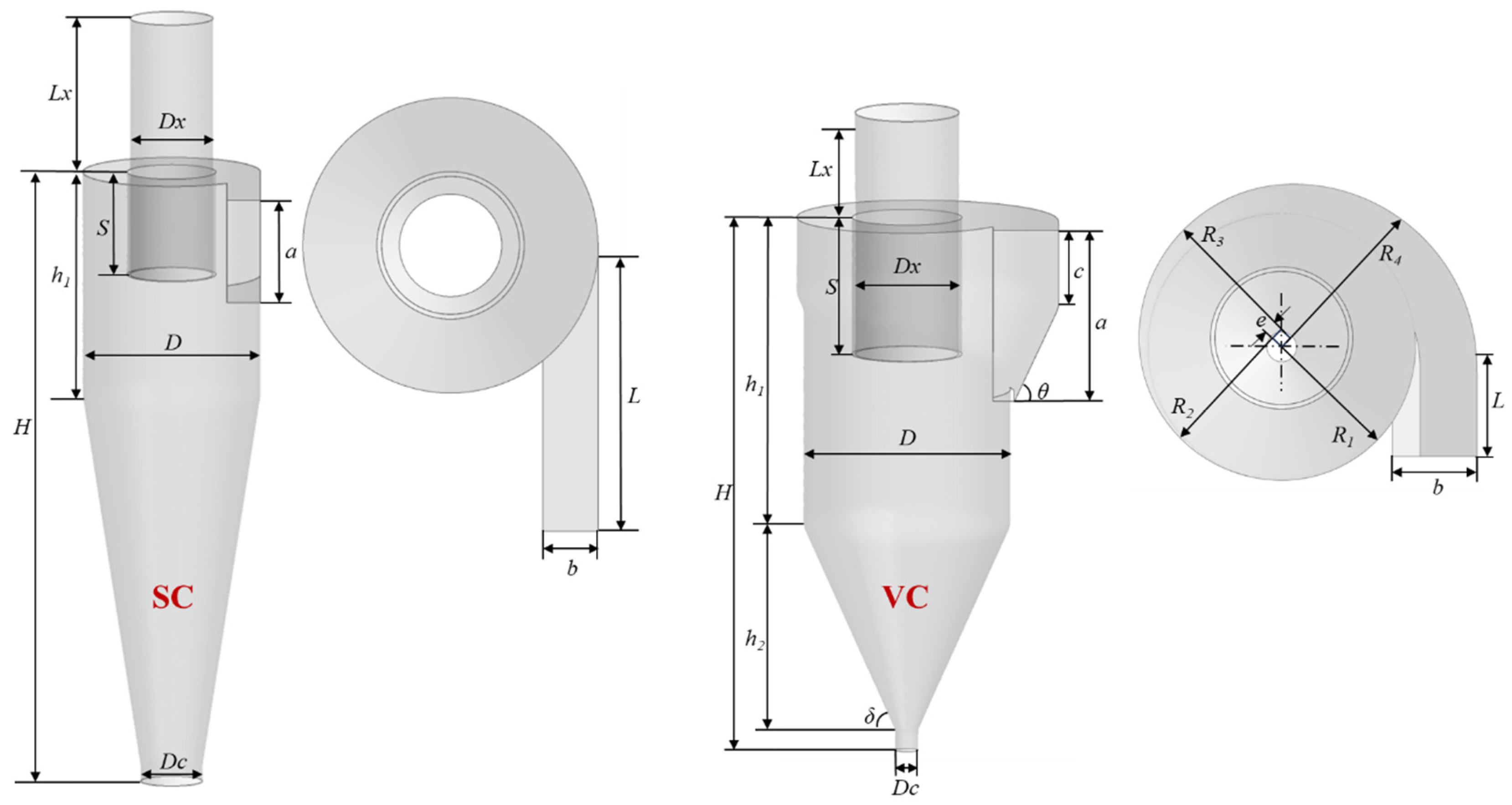
In current high-purity sodium sulfide production processes, the industry predominantly employs two types of separation equipment: standard Stairmand cyclones and volute cyclones. Recognizing their widespread application and operational relevance, this study has strategically selected these two configurations as the foundation for developing and optimizing secondary separation cyclone systems. The geometric parameters of the standard Stairmand cyclones (SC) and volute cyclones (VC) are presented in Figure 1, with the dimensions detailed in Table 1.
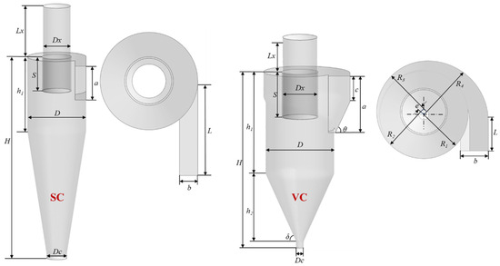
Figure 1.
Geometry diagram of the Stairmand cyclone separator.

Table 1.
Geometrical dimensions of the cyclone.
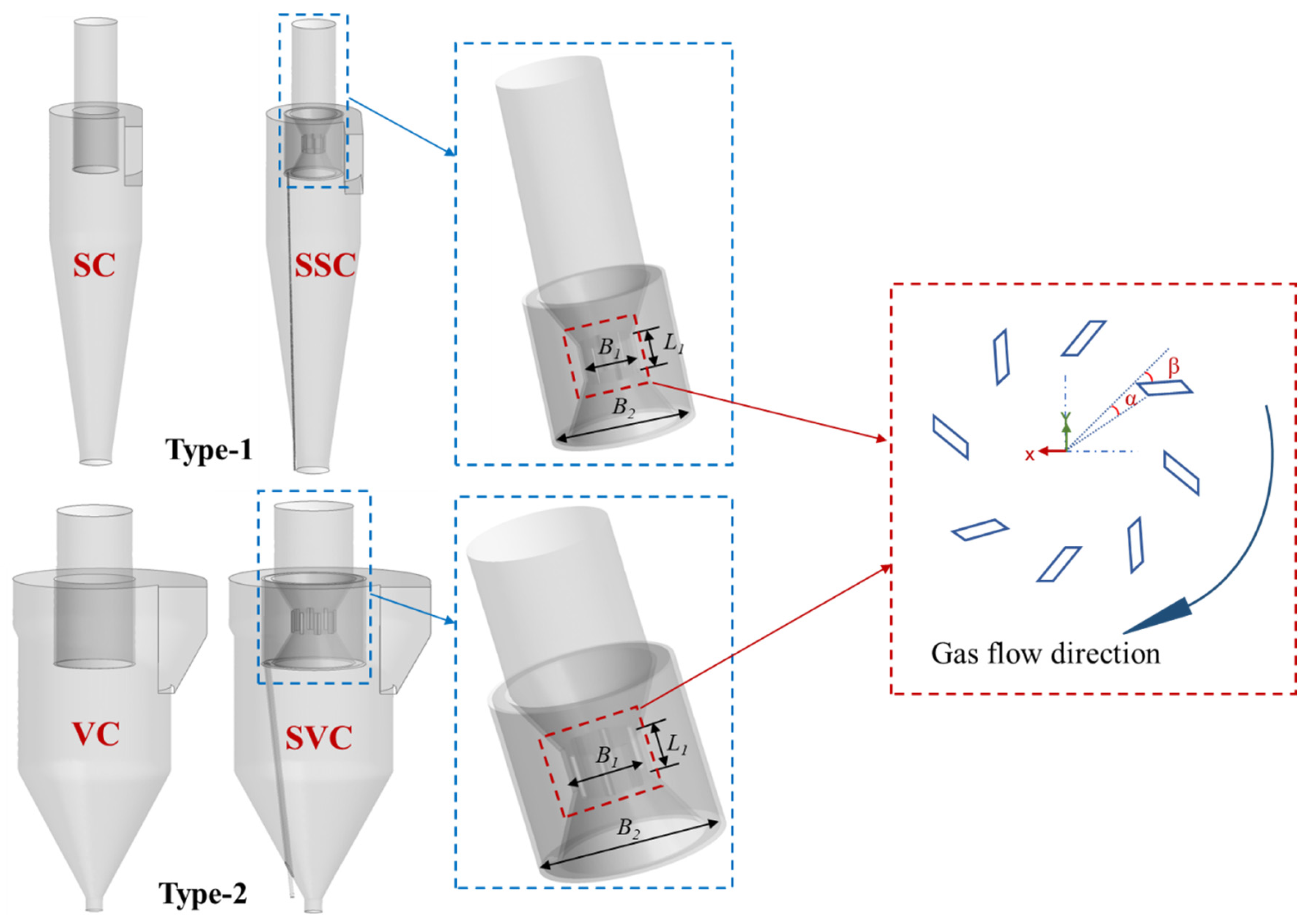
In this study, two types of cyclone separators were modified. Type 1 is a standard Stairmand cyclone, evaluated before and after the modification (SC and SSC). Type 2 is a volute cyclone, also assessed before and after modification (VC and SVC). The geometric details of these separators are illustrated in Figure 2. The entrance to the secondary separation structure is situated at the contraction midway along the inner cylinder of the riser, forming a slit with a parallelogram cross-section. The ratio of the slit length to the vortex finder length is defined as L1/S = 0.33, the number of slits is N = 8, the span angle is α = 15°, and the tilt angle is β = 45°. The fluid area between the inner cylinder and the secondary collection chamber is connected via the slit, while the diameter of the secondary collection chamber is represented as B2/L1 = 1.2. The secondary separation outlet is designed as a hollow circular tube with a diameter of 10 mm, featuring an independent outlet at the bottom.
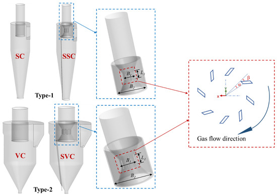
Figure 2.
Three-dimensional models of four cyclones in geometric detail.
2.3. Numerical Schemes and Boundary Conditions
This study presents the spatial discretization method for the three-dimensional cyclone separator model, based on the evaluation and discussion of various interpolation schemes in numerical simulations [16,18,19,27,28]. The performance of the cyclone separator is assessed at airflow inlet speeds of Vin = 10, 12.5, 15, and 17.5 m/s. Gas enters the cyclone separator through the intake pipe, which has a hydraulic diameter of 0.09 m. The gas discharges freely from the exhaust pipe, resulting in an export pressure of 0 Pa and a hydraulic diameter of 0.145 m. The particles move in conjunction with the airflow, entering the cyclone separator at the same velocity as the gas. Collisions between the particles and the wall surfaces are assumed to be completely elastic, with the wall surfaces adhering to standard wall functions and no-slip conditions. The particles exit through the outlet following separation in the conical section, with some being carried out by the airflow and discharged from the exhaust pipe. Details of the spatial discretization method and boundary conditions are provided in Table 2 and Table 3.
Table 2.
Summary of the spatial discretization methods.
Table 3.
Summary of boundary conditions.
The hydraulic diameter (DH) and turbulence intensity (IT) are calculated using the following formulas [29]:
where
A—Entrance cross-sectional area, m2;
L—Entrance perimeter, m.
2.4. Grid Independency Study
In this investigation, the computational domain was discretized using a hybrid polyhedral mesh structure generated through fluent meshing. To establish computational rigor, a comprehensive grid independence study was conducted by comparing simulation results across eight distinct grid refinement levels, as illustrated in Figure 3. The second grid level, demonstrating continuous error margins below 3%, was selected as the optimal computational grid, achieving an effective balance between computational accuracy and resource efficiency. The final mesh configurations resulted in total element counts of 626,623 for the SC-type, 955,288 for the SSC-type, 205,269 for the VC-type, and 1,508,497 for the SVC-type separator configurations.
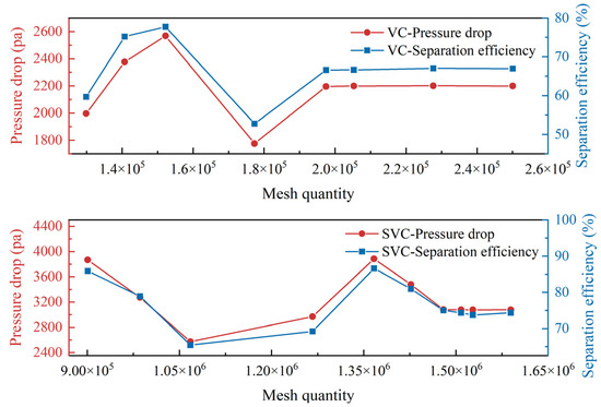
Figure 3.
Grid independence verification.
3. Experiments
3.1. Materials
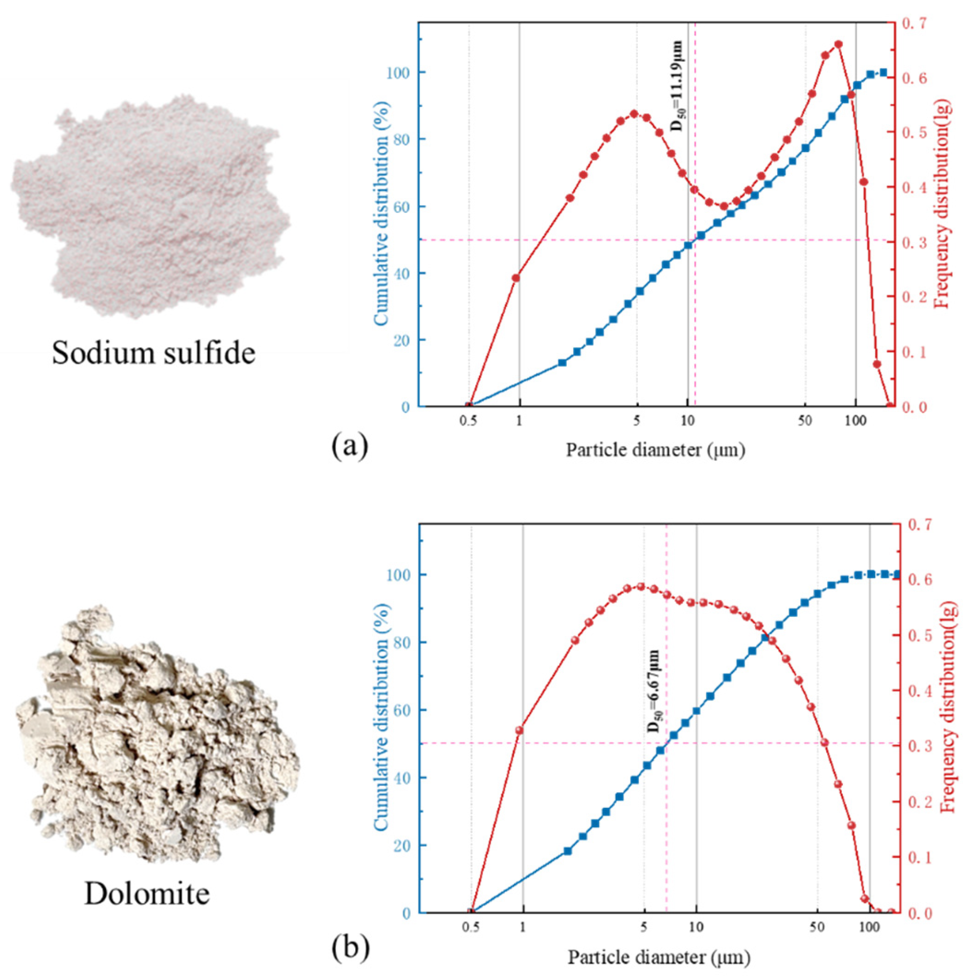
In the study conducted by He et al. [30] on the reduction of Na2SO4 to Na2S using dilute phase fluidization technology, Figure 4a illustrates both the particle size distribution and physical characteristics of the synthesized sodium sulfide. The produced Na2S exhibits a distinct light pink coloration, with a median particle size of D50 = 11.19 μm. This particle size distribution reveals that approximately 50% of the particles have diameters below 10 μm, underscoring the fine particulate nature of the final product. Due to the compound’s hygroscopic nature in atmospheric conditions, strong alkaline properties, corrosive characteristics, and inherent toxicity, the test materials cannot be reused for subsequent experiments. Considering both safety protocols and cost-effectiveness, dolomite powder was selected as an alternative test material, demonstrating comparable particle size distribution with a smaller median particle size, as presented in Figure 4b.
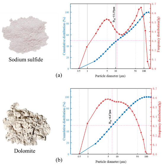
Figure 4.
Particle size distribution used in this study, (a) Sodium sulfide, (b) Dolomite.
3.2. Test System and Model
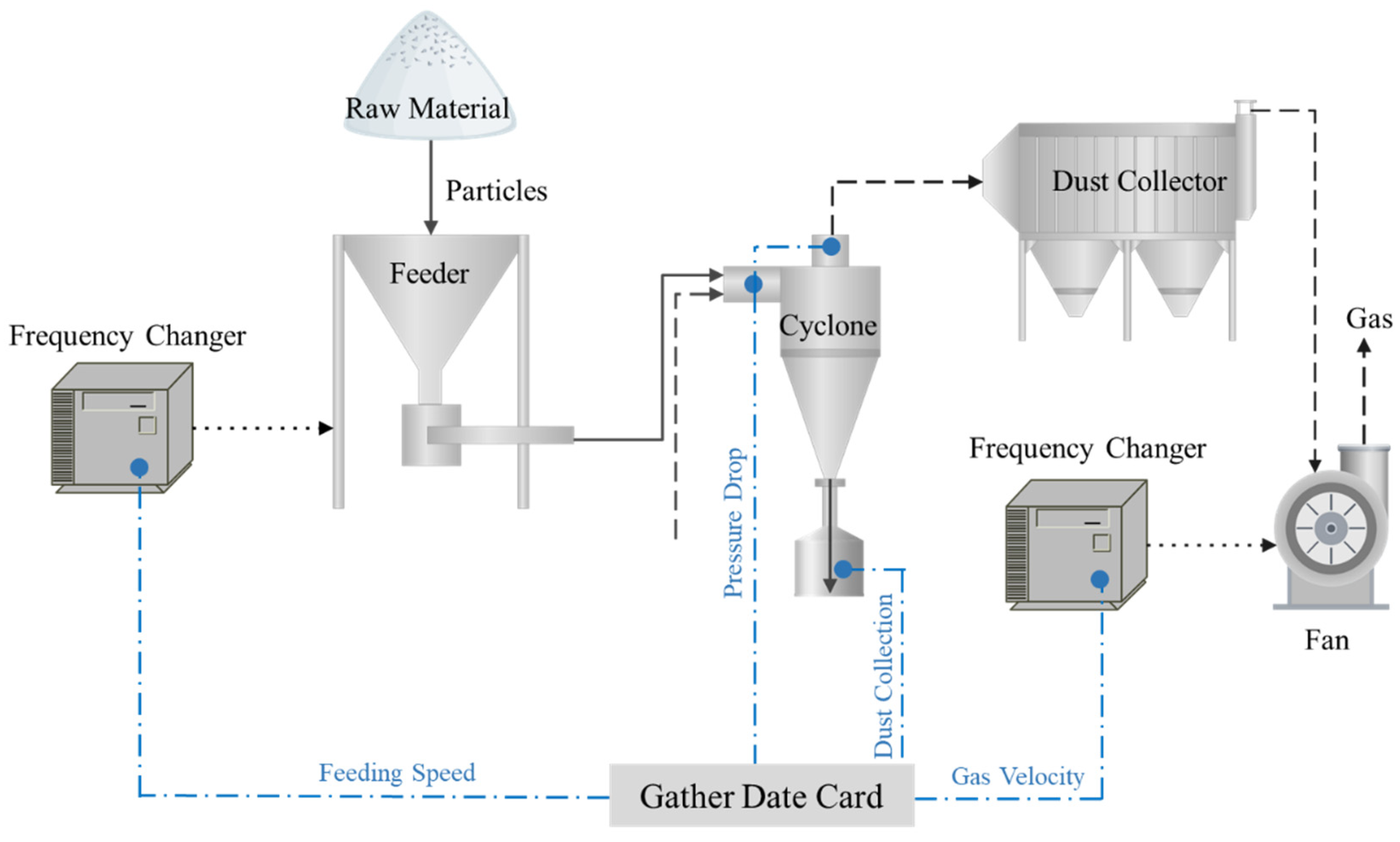
The experimental configuration incorporates specifically engineered transparent models, including a plexiglass observation module designed for the enhanced visualization of intraparticle dynamics. To ensure experimental accuracy and eliminate potential electrostatic interference, the plexiglass model was properly grounded. The detailed dimensional specifications of the model are provided in Table 1. Figure 5 presents the fully instrumented test rig that integrates sequential processing modules, including an automated feeding system, a secondary separation cyclone, a particulate collection assembly, a multi-stage filtration mechanism, and a variable-speed drive unit, whose engineering parameters are systematically cataloged in Table 4. Zhang [27] constructed a similar test platform to investigate the effects of variations in the structural parameters of the lower-row cyclone separator on its performance. The material is fed into a novel secondary separation cyclone separator operating under negative pressure conditions via the feeder. The materials undergo initial separation, with the separated ash entering the ash bucket. Subsequently, the remaining material is further cleaned by passing through the filter before being discharged into the atmosphere by the ventilator. The feeding speed and airflow during system operation are regulated by a frequency conversion controller.
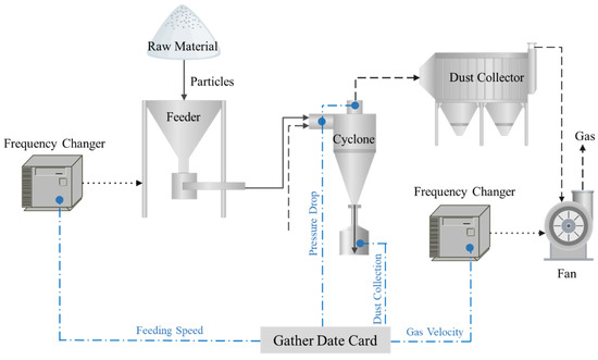
Figure 5.
Flowchart of the experimental apparatus.
Table 4.
Equipment Type.
3.3. Validation of Numerical Simulation
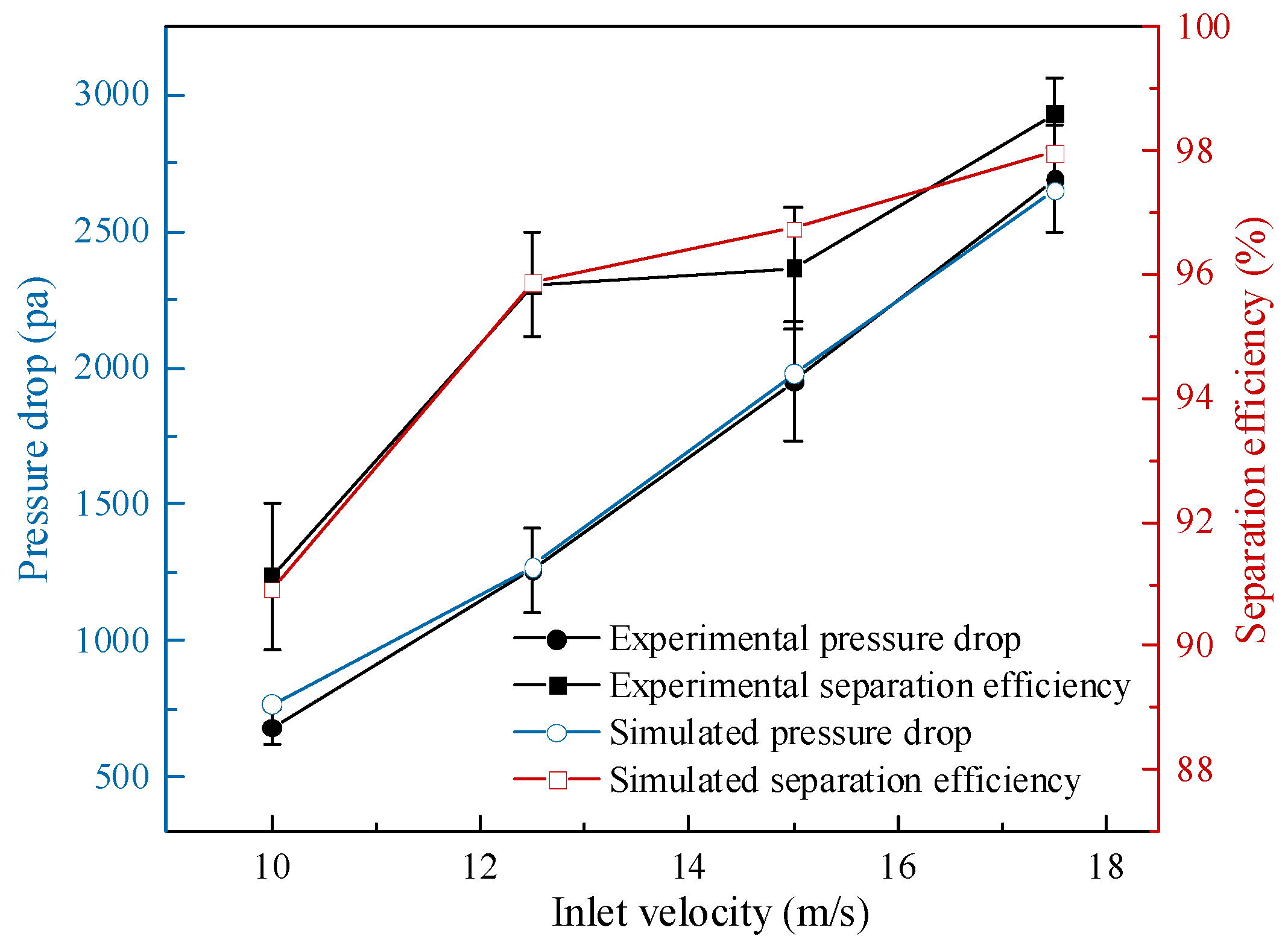
The experimental results of the secondary separation cyclone were used to validate the CFD simulation, as illustrated in Figure 6. The inlet wind velocity employed in the experiment aligns with the boundary conditions used in the numerical simulation. The particle size distribution was defined using the Rosin–Rammler model, with a particle size range of 1–10 μm, a median particle size of D50 = 6.67 μm, and a dispersion coefficient of n = 2.64. This distribution closely matches the particle size characteristics of the experimental raw material for particles smaller than 10 μm. The experimental data exhibit reasonable errors, and the simulation results demonstrate a consistent trend with the experimental findings. Taking Vin = 12.5 as an example, the experimental pressure drop was 1521 ± 77 Pa (95% CI), while the simulated value was 1507 Pa, yielding a minimal absolute error of only 14 Pa. Similarly, for the corresponding efficiency metric, the experimental value was 96.02% ± 0.87% (95% CI) compared to the simulation result of 95.88%, resulting in an absolute error of merely 0.14%. Critically, the 95% confidence intervals for all data points encompassed the respective simulated values. Furthermore, discrepancies across all other experimental groups were consistently less than 0.5%. The strong agreement between the experimental and simulated trends is further evidenced by a high coefficient of determination (R2 = 0.98).
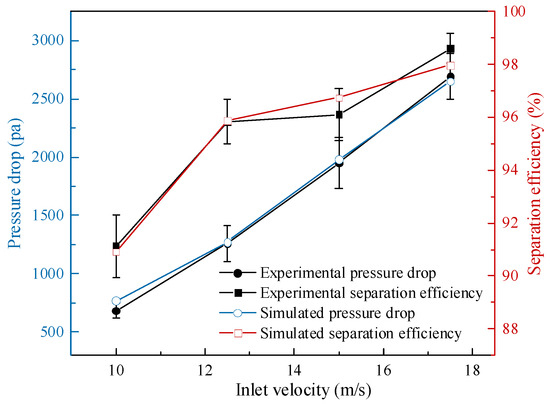
Figure 6.
Comparison of the experimental and simulated result under different air volume conditions.
4. Results and Discussion
4.1. Particle Separation Efficiency
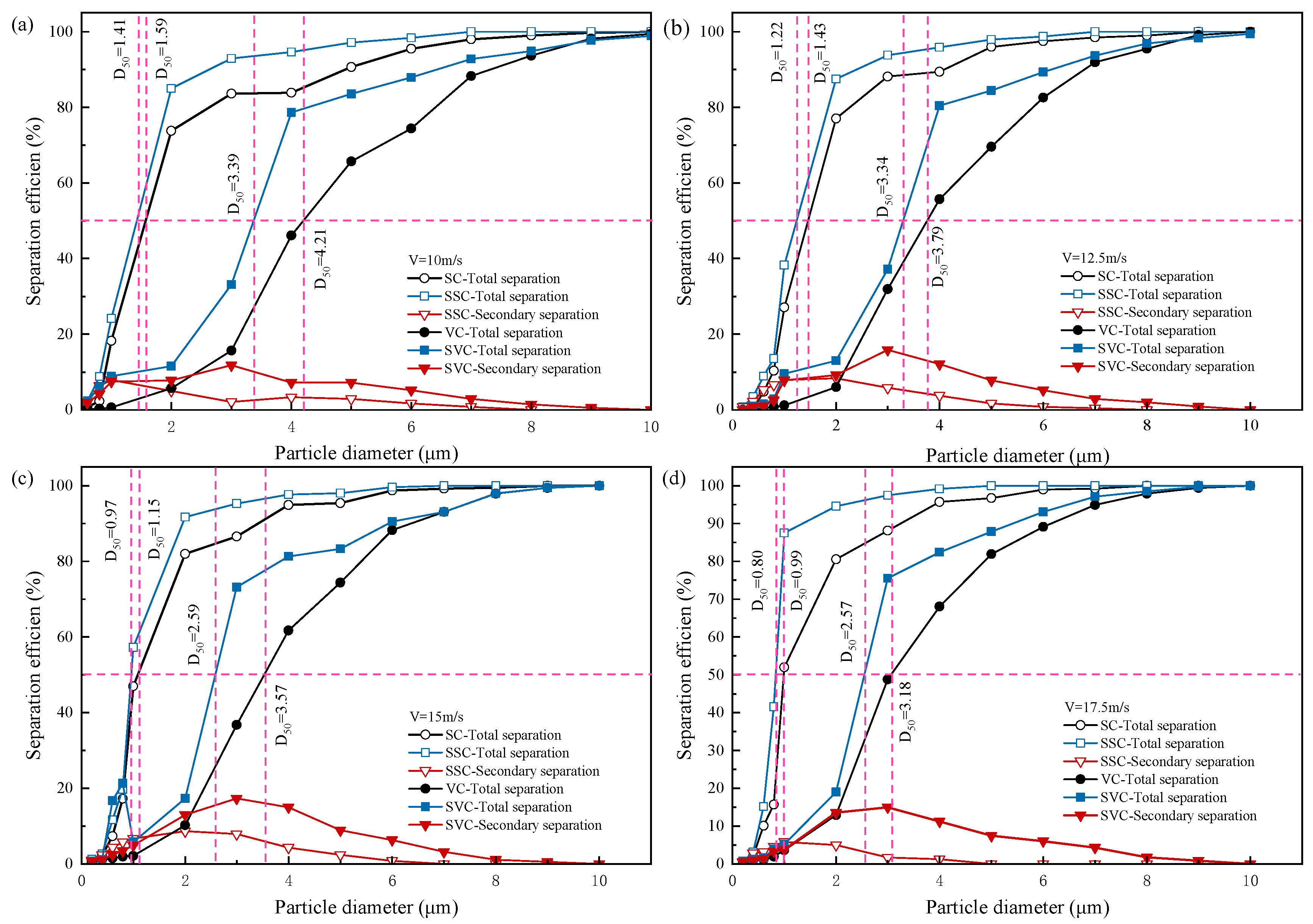
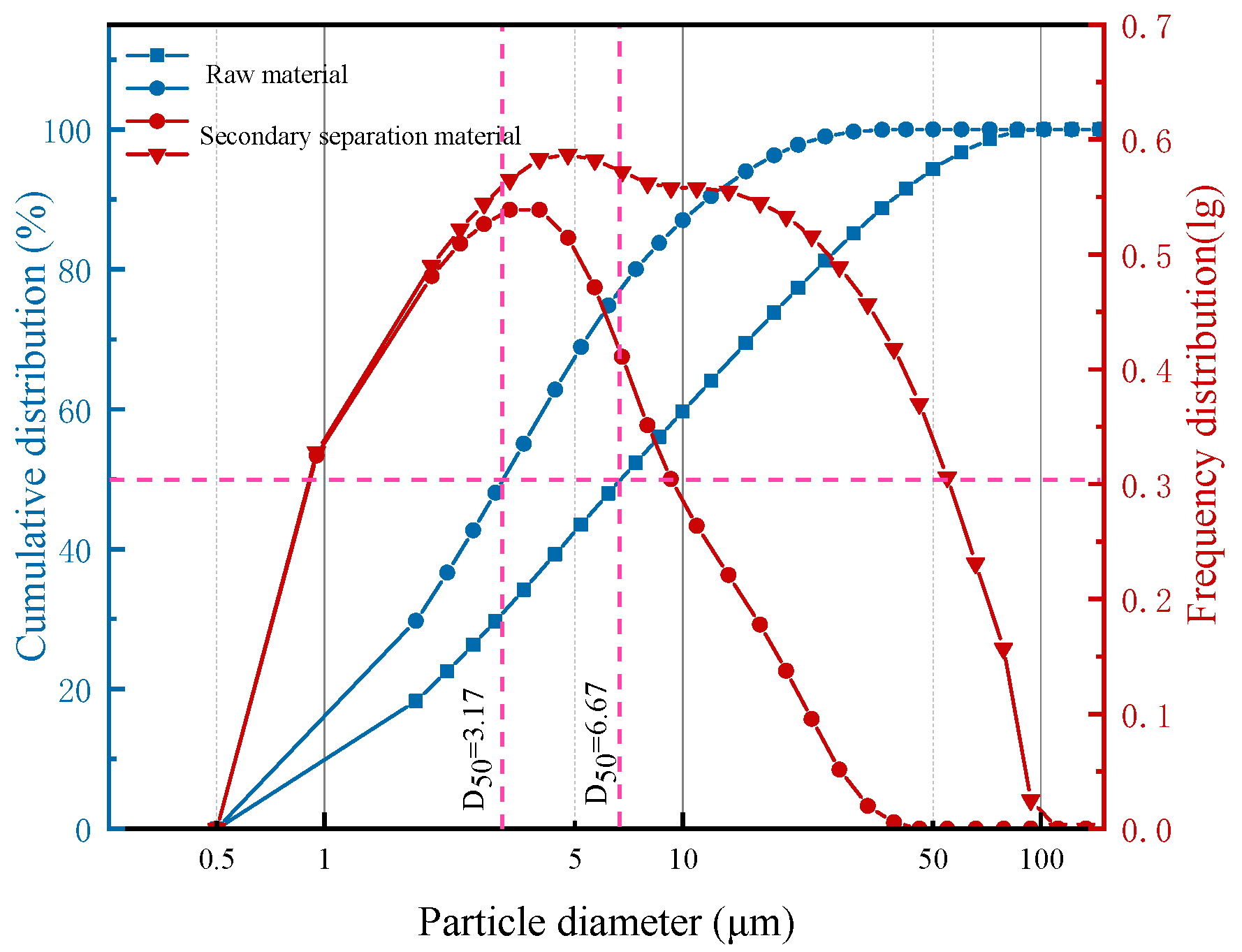
Table 5 summarizes the total separation efficiency of the two cyclone separators before and after modification at four inlet velocities. Compared to the pre-modification performance, the total separation efficiency of the secondary separation-type cyclone shows significant improvement across all four gas velocities. The classification separation efficiency, derived from the statistical analysis, is presented in Figure 7, which reveals a notable reduction in the cutting particle size following the implementation of the secondary separation structure. The secondary separation structure demonstrates optimal performance in capturing 1–4 μm particles, with the highest capture proportion observed for 3 μm particles. At the Vin = 15 m/s, the capture proportions for the SSC type and SVC type reach 9.37% and 17.29%, respectively. Repeated experiments confirmed these findings, as shown in Figure 8, with the median particle size, D50, of particles captured by the secondary separation structure decreasing by 52.47% compared to the raw material. In previous work by Guo et al. [16,31], a slotted vortex structure—bearing similarity to the secondary separation inlet’s local configuration examined in the present study—was investigated using particle models within the 2–3 μm size range. Their optimized design achieved a 4.32-percentage point increase in collection efficiency and a 5.53% reduction in cut-off size. By contrast, the current study demonstrates superior collection efficiency performance. Nevertheless, the multi-objective optimization methodology established by Guo et al. retains significant methodological relevance.
Table 5.
Separation efficiency of two cyclone separators at different inlet speeds.
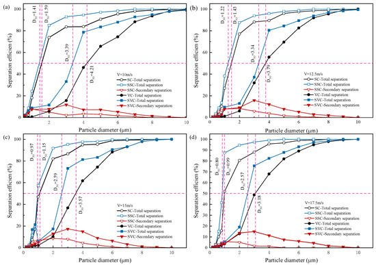
Figure 7.
Classification separation efficiency of two types of cyclones at four inlet speeds, (a) V = 10 m/s, (b) V = 12.5 m/s, (c) V = 15 m/s, (d) V = 17.5 m/s.
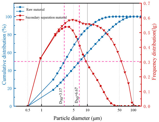
Figure 8.
Secondary separation particles and raw material size distribution.
4.2. Velocity Distribution
Since the flow field distribution exhibits similar patterns across different gas velocities, the following discussion focuses solely on the case in which the inlet velocity Vin = 10 m/s.
4.2.1. Axial Velocity
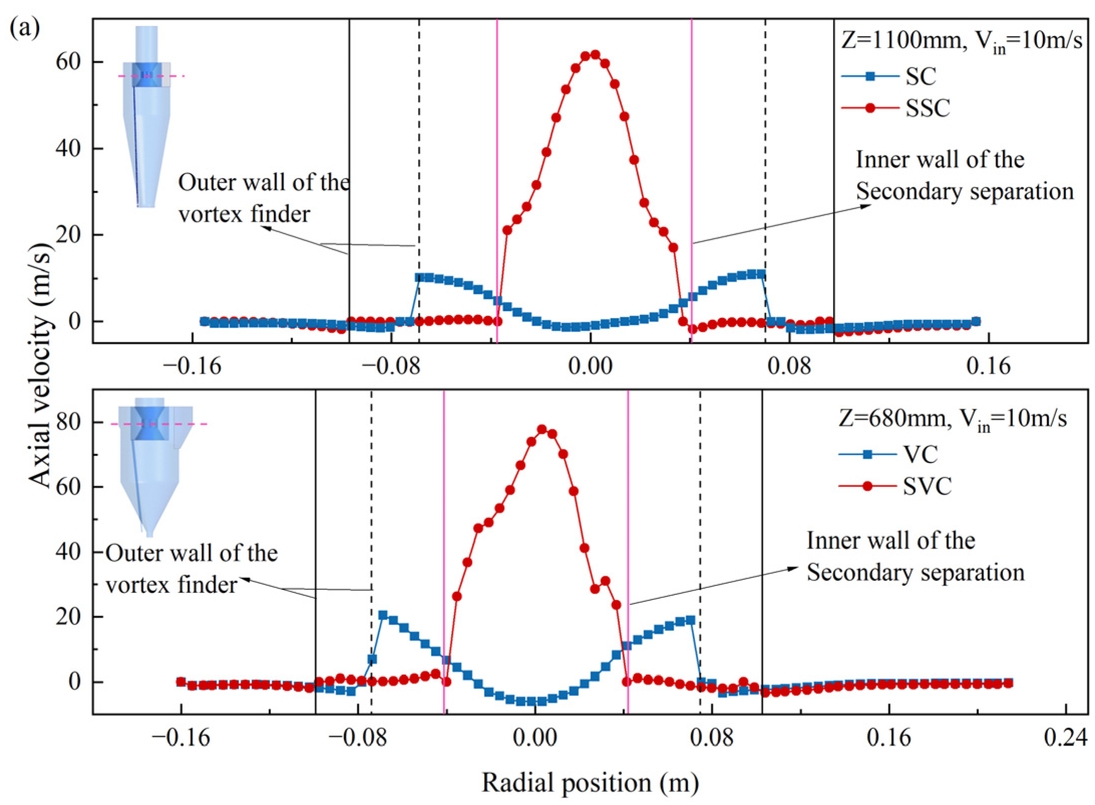
Figure 9 illustrates the axial velocity distribution comparison between the entrance and the cone section of the secondary separation structure in a cyclone separator. Compared to the pre-modification state, the downward axial velocity near the SSC wall increases, promoting the downward movement of particles. Additionally, as shown in Figure 9a, the velocity distribution in the SC and VC vortex finders exhibits a “V” shape. In engineering applications, this pattern can lead to longer particle residence times and exacerbate local abrasion. In Figure 9b, the low axial velocity at the axis extends into the separation section, increasing the instability of the internal swirl and negatively impacting separation efficiency. In contrast, after the modification, the axial velocity in both the vortex finder and the section exhibits an inverted “V” distribution, resulting in a more stable airflow.

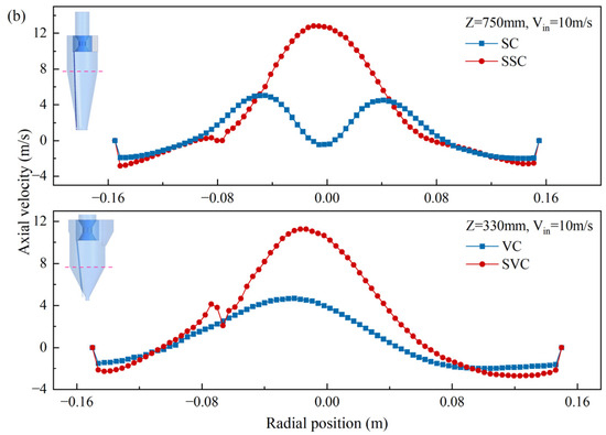
Figure 9.
Axial velocity of two types of cyclone separators, (a) Secondary separation entrance, (b) separation section.
4.2.2. Tangential Velocity
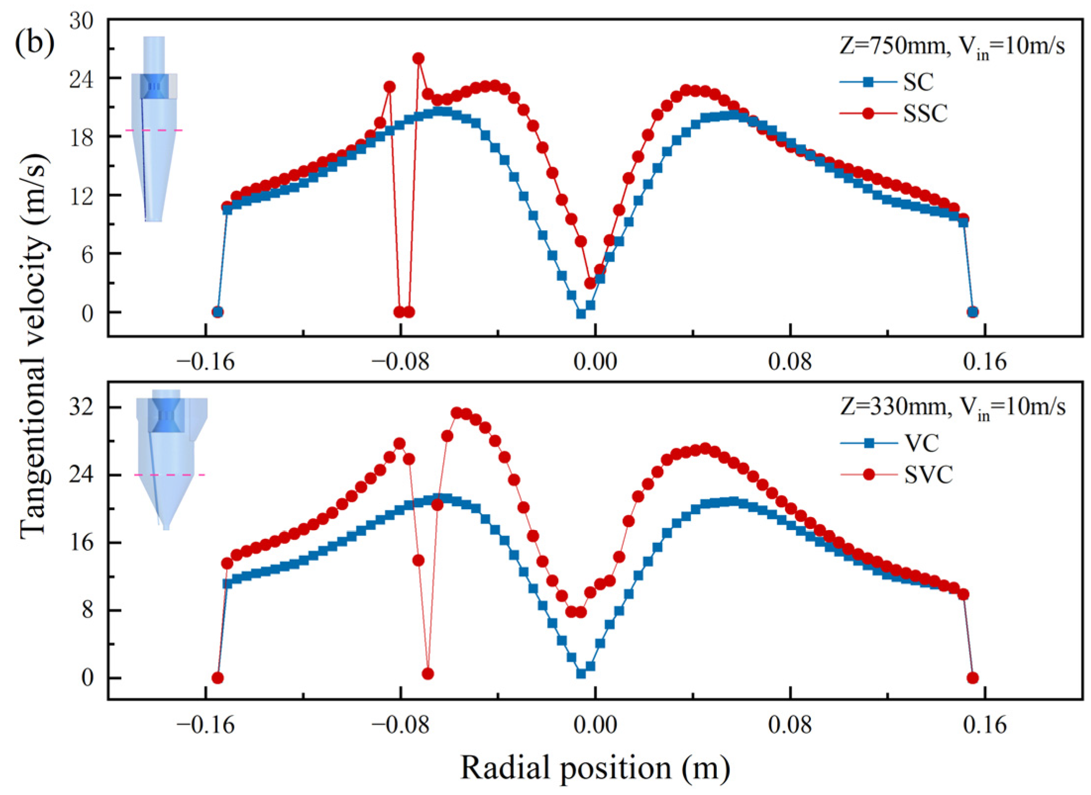
As shown in Figure 10, the tangential velocity distribution at the same location is compared. In Figure 10a, the tangential velocity at the secondary separation inlet of the SSC and SVC cyclones increases by approximately 140% to 160% across all four gas velocities. This enhancement allows particles to experience greater centrifugal force, facilitating the entry of fine particles into the secondary separation structure, where they are captured. This mechanism significantly improves the separation efficiency of fine particles. In the separation section depicted in Figure 10b, the tangential velocity near the wall shows a slight increase after modification, while the tangential velocity of the inner swirl rises substantially. This indicates that the inner swirl diameter of the modified cyclone is narrower. When the tangential velocity remains constant, a smaller rotation radius results in greater centrifugal force on the particles, promoting their movement toward the wall and enhancing separation efficiency.
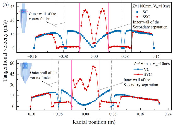
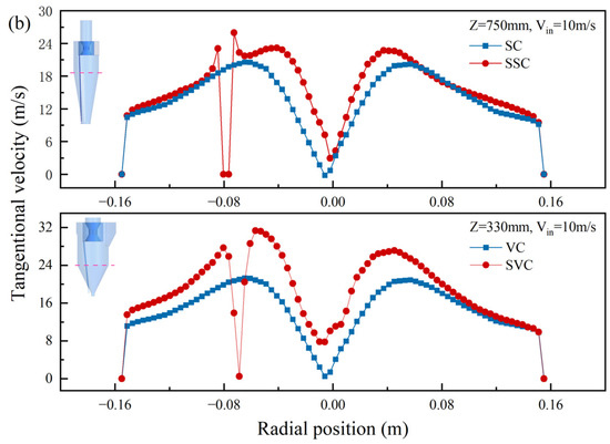
Figure 10.
Tangential velocity of two types of separators, (a) Secondary separation entrance, (b) separation section.
4.3. Pressure Distribution
4.3.1. Static Pressure Distribution
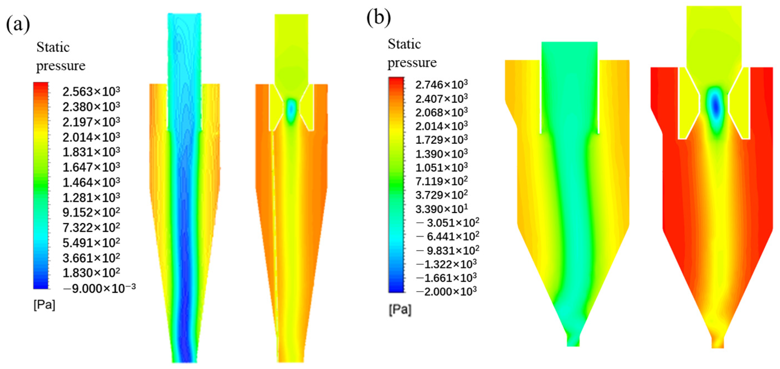
To analyze the overall static pressure distribution in the cyclone separator before and after modification, cloud images are used to visually represent the static pressure distribution, as shown in Figure 11. It can be observed that the modified cyclone exhibits higher static pressure overall, but the distribution pattern remains consistent: the static pressure is higher near the wall of the cyclone separator, while the low-pressure area is concentrated along the central axis. A negative pressure zone appears at the secondary separation entrance of both the SSC and SVC, which contributes to an increase in local pressure loss.

Figure 11.
Contour of static pressure of cyclones, (a) Type-1, (b) Type-2.
4.3.2. Regional Pressure Drop
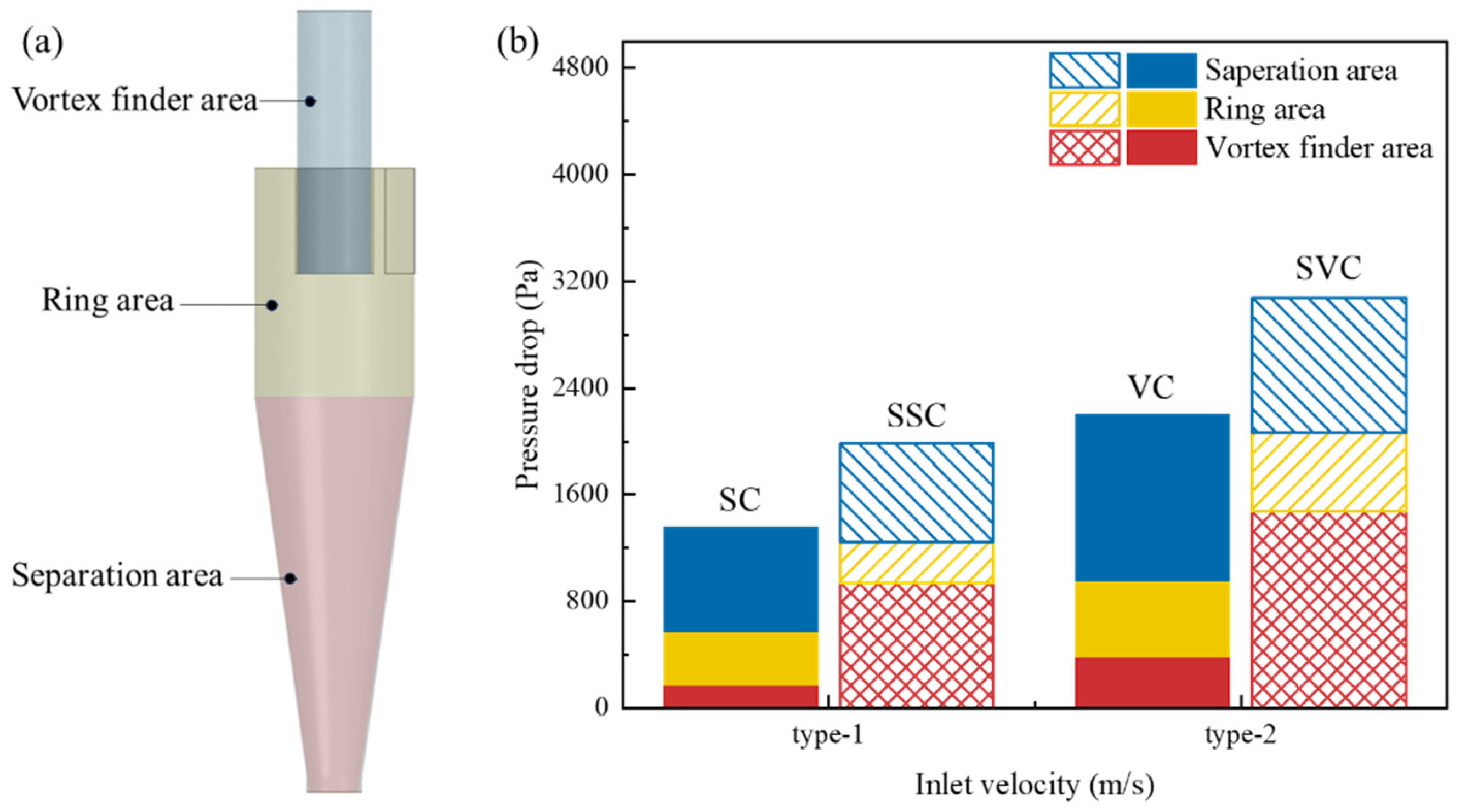
To further analyze the impact of the secondary separation structure on pressure drop, the cyclone was divided into three zones: the vortex finder zone, the ring zone, and the separation zone, as illustrated in Figure 12a. The primary pressure loss in the SC and VC cyclones occurs in the separation zone, accounting for over 50% of the total pressure drop. The pressure loss in the vortex finder zone contributes to at least 18% of the total pressure drop; however, since the vortex finder does not participate in particle separation and merely serves as a gas escape channel, this pressure loss holds no practical significance and only represents energy loss, which does not benefit separation efficiency. In contrast, the SSC and SVC cyclones exhibit reduced pressure losses in the ring and separation zones compared to their pre-modification states, while the pressure loss in the vortex finder zone increases. Although this results in some energy loss, the secondary separation structure in the vortex finder enables the secondary capture of escaping fine particles, thereby improving overall separation efficiency.
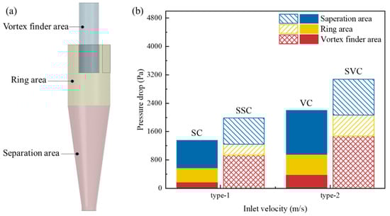
Figure 12.
(a) Cyclone separator partition indication, (b) regional pressure drop.
4.4. Vortex Distribution
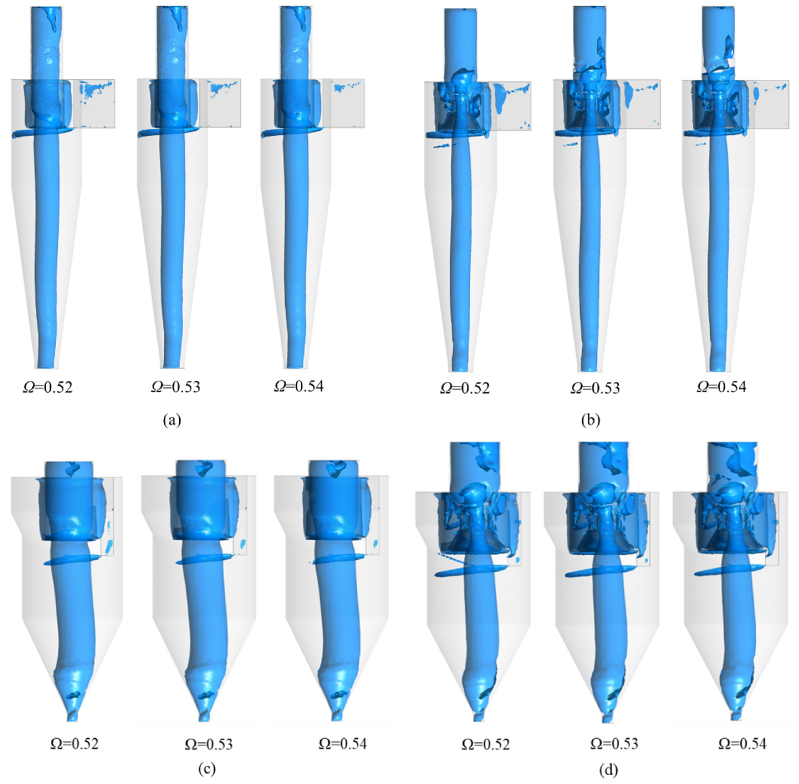
4.4.1. Iso-Vortex Surfaces
Based on a comparison of previous methods for iso-vortex surface identification in cyclone separators, this study adopts the latest Ω method for vortex surface identification [32,33,34,35,36]. As shown in Figure 13, The overall vortex distribution pattern in the cylinder of the cyclone separator remains similar before and after modification, with distinct vortex core structures present in both cases. After modification, small vortices are clearly observed at the secondary separation structure, while irregular vortices at the vortex finder of the secondary separation inlet indicate significant airflow turbulence in this region. This turbulence is the primary cause of the increased pressure loss observed here. Additionally, the vortex core diameter of the modified SSC and SVC cyclones is narrower, suggesting that the airflow in the barrel and cone sections becomes more stable and concentrated after modification. These characteristics align with the observed changes in the velocity distribution in these regions.
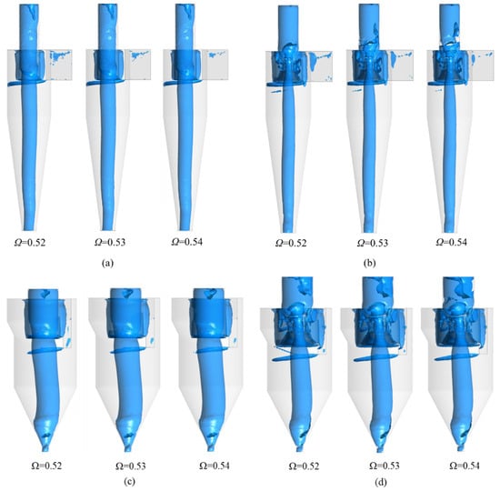
Figure 13.
Iso-vortex surfaces of cyclone separator, (a) SC, (b) SSC, (c) VC, (d) SVC.
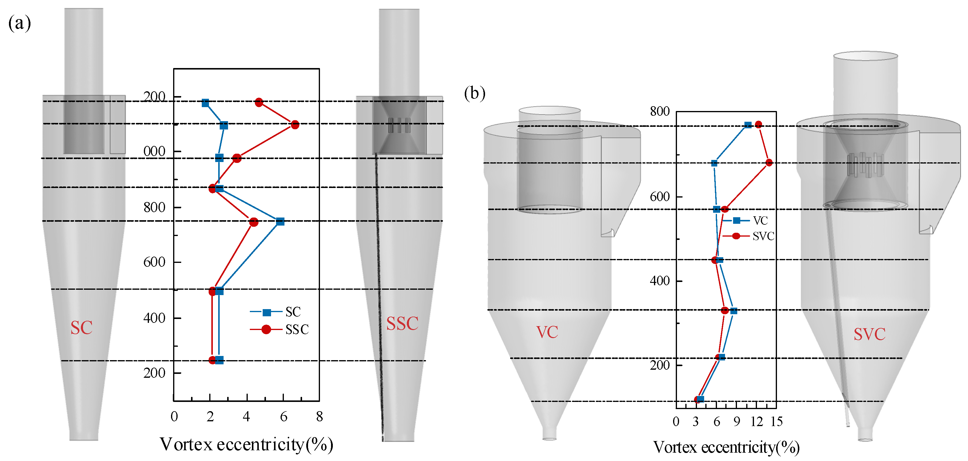
4.4.2. Eccentricity of the Vortex Core
As shown in Figure 14, after the secondary separation structure is added, the eccentricity of the vortex core in both the cylinder and the separation section decreases, which is conducive to reducing particle remixing and pressure loss in this region. However, the eccentricity of the vortex core of the SSC and SVC types in the vortex finder region is larger, which indicates that there is a larger turbulence intensity here. It is also the reason for the greater pressure loss here. These characteristics are consistent with the law of pressure distribution.
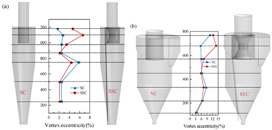
Figure 14.
Eccentricity of vortex core of cyclone separator, (a) Type-1, (b) Type-2.
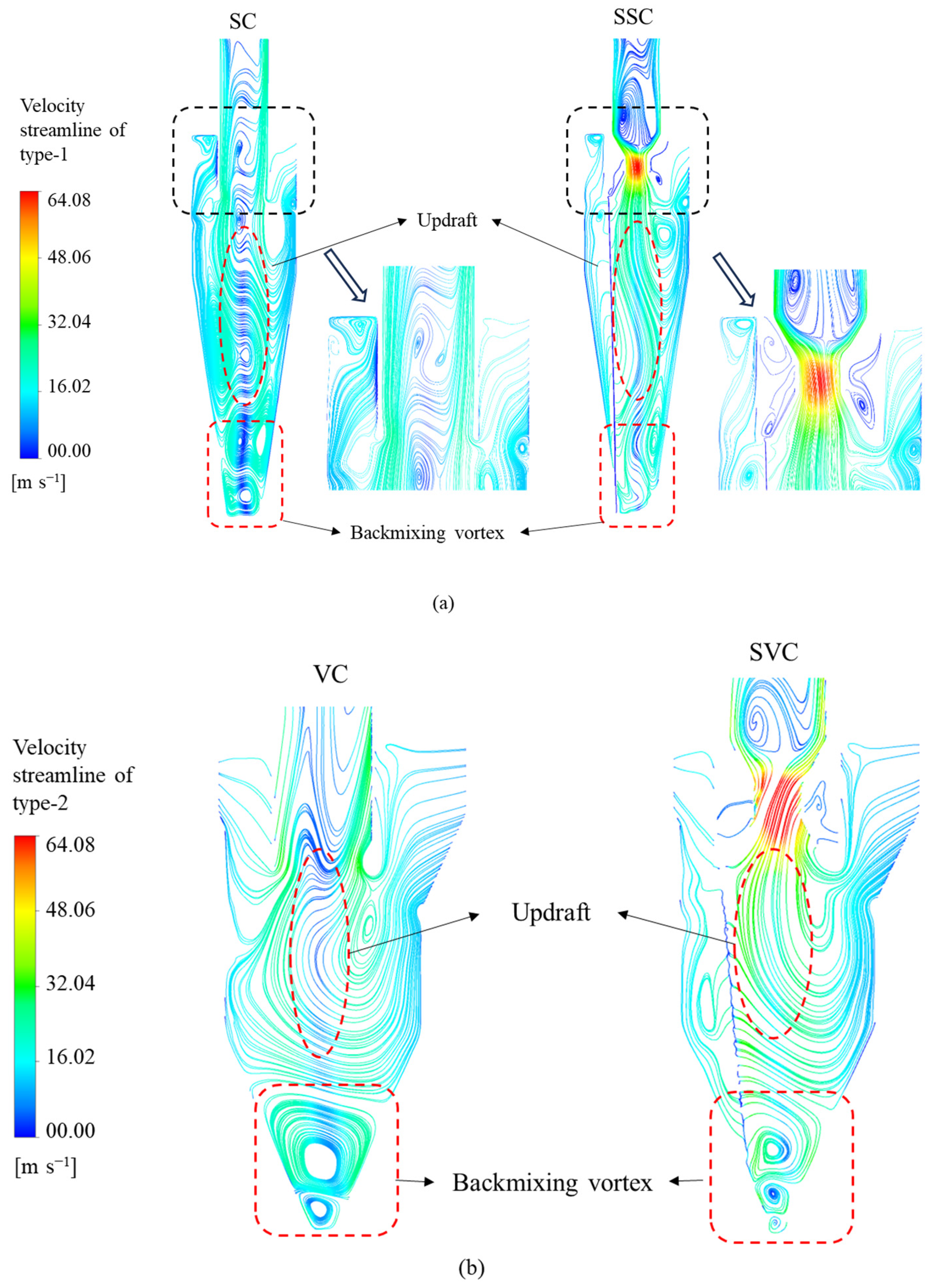
4.5. Particle Behavior
To more intuitively demonstrate the effect of the secondary separation structure on particle movement in cyclone separators, the airflow and particle distribution of two cyclone separators were analyzed. Figure 15 illustrates the streamline distribution of the two cyclones at the y = 0 position. After modification, the streamline along the central axis of the cyclones is significantly straightened, indicating the presence of a distinct updraft in this region. This observation aligns with the results of the axial velocity distribution analysis. Additionally, the back mixing vortex at the bottom of the cone section is notably improved, further enhancing the overall flow stability. This clearly illustrates the movement trajectory of fine particles captured by the secondary separation structure.
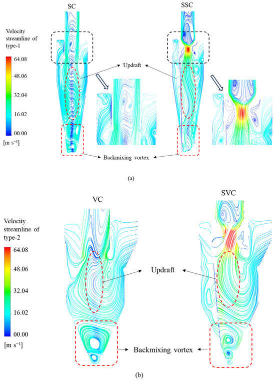
Figure 15.
Streamlines on section y = 0 cyclones, (a) Type-1, (b) Type-2.
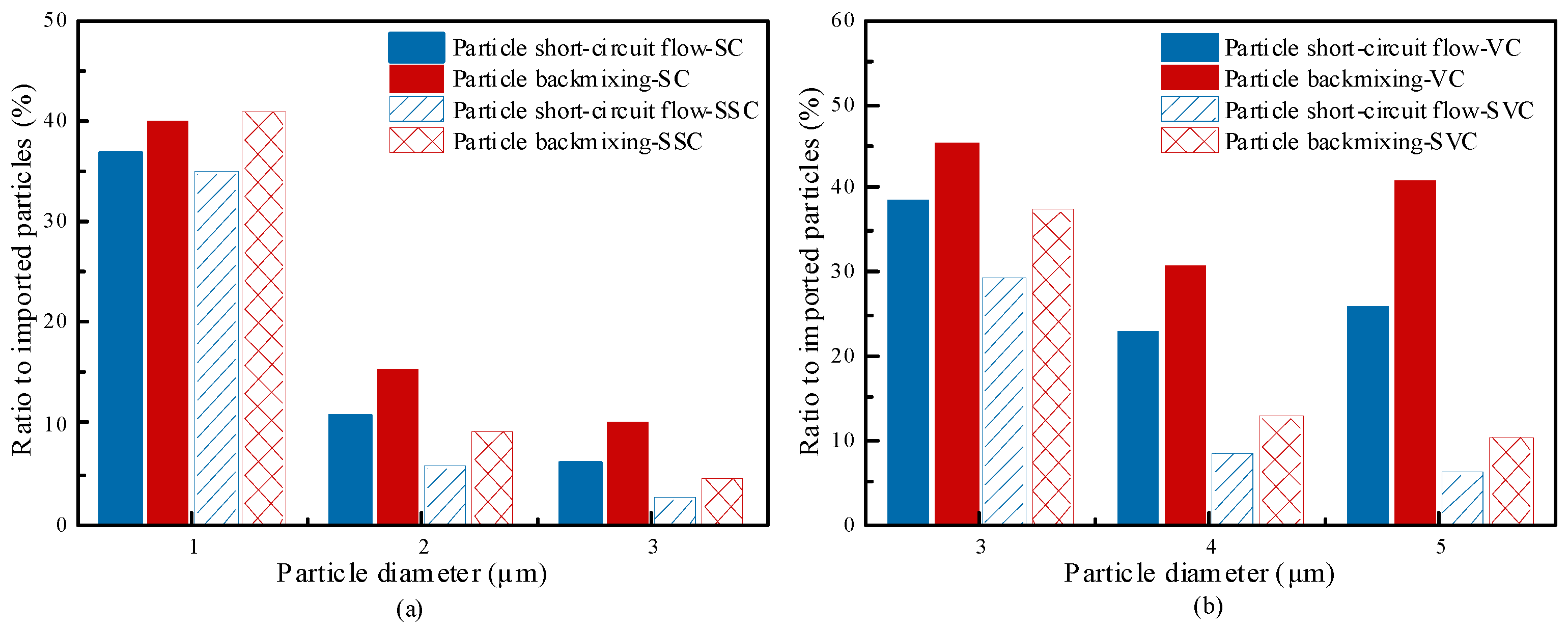
Building upon the characterized flow field properties, we investigate the modification’s impact on fine particle dynamics through residence time distribution (RTD) analysis. Figure 16 reveals that pre-modification E(t) profiles for representative particle sizes (3 μm, 5 μm, and 8 μm) exhibit persistent minor peaks following the primary maximum—particularly pronounced in 3 μm particles—indicating flow instability and particle reflux. Post-modification, however, a distinct secondary peak emerges after the primary E(t) maximum, demonstrating successful particle recapture by the secondary separation structure. Concurrently, E(t) amplitude decreases with increasing particle size, which is consistent with previously reported classification efficiency trends. Crucially, the modification significantly narrows the temporal span of the primary peak while amplifying the secondary peak, confirming enhanced flow stability. Quantitative analysis of particle escape mechanisms (Figure 17b) further shows the substantial redistribution of loss pathways, with marked reductions in short-circuiting and reverse mixing across all sizes. These modifications correlate directly with significantly improved collection efficiency, confirming the two-stage structure’s effectiveness in capturing escape-prone particles—particularly in SVC separators where baseline performance was suboptimal.
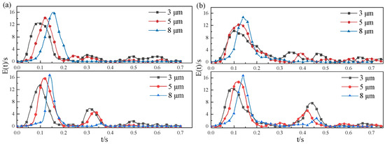
Figure 16.
Particle residence time distribution density function, (a) Type 1, (b) Type 2.
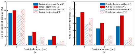
Figure 17.
Proportion of particle escape modes, (a) Type 1, (b) Type 2.
5. Conclusions
The primary objective of this study is to optimize the secondary separation of cyclone separators used in the Na2S production process, aiming to enhance the separation efficiency of fine particles. By combining numerical simulation with experimental methods, the trial-and-error costs are reduced, and the impact of the secondary separation structure on the internal flow field and performance of the cyclone is thoroughly investigated. The main conclusions of the study are as follows:
- (1)
- The simulation results exhibit a high degree of consistency with the experimental results. By ensuring the reliability of the findings, the study achieves its goal of reducing trial-and-error costs through numerical simulation.
- (2)
- The secondary separation structure proposed in this study effectively improves the separation efficiency of fine particles in two types of cyclone separators commonly used in the Na2S production process.
- (3)
- The secondary separation structure suppresses short-circuit flow and particle back-mixing, markedly reducing the cut size.
6. Future Work
To advance the industrial implementation of the secondary separation cyclone, deeper investigations into practical challenges remain essential. Key directions are as follows:
- (1)
- Industrial Validation and Durability Testing: While acrylic models were employed for particle trajectory visualization in this study, future work must adopt industrially representative materials and rigorously evaluate localized erosion effects on component degradation.
- (2)
- Energy-Efficiency Optimization: Subsequent research should establish cost–benefit frameworks that balance enhanced fine-particle collection efficiency with associated energy consumption penalties to determine economic viability.
Author Contributions
Conceptualization, J.C.; data curation, J.C.; formal analysis, L.Z.; funding acquisition, Y.C. and B.Z.; investigation, J.C.; methodology, J.C.; project administration, Y.C. and B.Z.; resources, Y.C.; supervision, Y.C. and B.Z.; validation, J.C.; visualization, Y.C. and B.Z.; writing—original draft, J.C.; writing—review and editing, Y.C. and Y.L. All authors have read and agreed to the published version of the manuscript.
Funding
The authors are grateful to the Key R&D Program of Shaanxi Province (number: 2023GXLH-052) and the Shaanxi key scientific and technological innovation team (2021TD-53) for the financial support for this work.
Data Availability Statement
The original contributions presented in this study are included in the article. Further inquiries can be directed to the corresponding author.
Conflicts of Interest
The authors declare no conflicts of interest.
References
- Wu, J.; Chen, Z.K.; Chen, J. The Application of Sodium Sulphide on Flotation of one Refraclory Tin-Copper Sulfide Ore. Yunnan Metall. 2017, 1, 28–32. [Google Scholar]
- Wan, H.M. The application of sodium sulfide to separation of Pb-Zn middings. Conserv. Util. Miner. Resour. 2000, 4, 2. [Google Scholar]
- Guo, M.; Yang, L.; Son, H.; Le, D.K.; Manickam, S.; Sun, X.; Yoon, J.Y. An overview of novel geometrical modifications and optimizations of gas-particle cyclone separators. Sep. Purif. Technol. 2024, 329, 125136. [Google Scholar] [CrossRef]
- Yang, L.; Chen, X.; Huang, C.; Liu, S.; Ning, B.; Wang, K. A review of gas-liquid separation technologies: Separation mechanism, application scope, research status, and development prospects. Chem. Eng. Res. Des. 2024, 201, 257–274. [Google Scholar] [CrossRef]
- Karagoz, I.; Avci, A.; Surmen, A.; Sendogan, O. Design and performance evaluation of a new cyclone separator. J. Aerosol Sci. 2013, 59, 57–64. [Google Scholar] [CrossRef]
- Zhang, Z.; Shao, M.; Ling, X. Experimental study on the separation performance of a novel gas–liquid separator. Adv. Powder Technol. 2022, 33, 103795. [Google Scholar] [CrossRef]
- Huang, L.; Deng, S.; Chen, Z.; Guan, J.; Chen, M. Numerical analysis of a novel gas-liquid pre-separation cyclone. Sep. Purif. Technol. 2018, 194, 470–479. [Google Scholar] [CrossRef]
- Wang, J.; Zhang, J. Investigation of velocity and magnetic field effects in an improved electrostatic cyclone precipitator for removal of submicron particles. Fuel 2025, 379, 133035. [Google Scholar] [CrossRef]
- Safikhani, H.; Allahdadi, S. The effect of magnetic field on the performance of new design cyclone separators. Adv. Powder Technol. 2020, 31, 2541–2554. [Google Scholar] [CrossRef]
- Zhang, C.-A.; Zhu, Z.-L.; Gao, G.-Y.; Fan, P.-P.; Fan, M.-Q. Effect of coaxial electromagnetic field on separation density of dense-medium cyclone. Miner. Eng. 2019, 138, 188–194. [Google Scholar] [CrossRef]
- Luckner, H.J.; Gradoń, L.; Ciach, T.; Podgórski, A.; Wertejuk, Z. Dust removal in cyclones with external electric field. J. Aerosol Sci. 1997, 28, S299–S300. [Google Scholar] [CrossRef]
- Lim, K.S.; Kim, H.S.; Lee, K.W. Comparative performances of conventional cyclones and a double cyclone with and without an electric field. J. Aerosol Sci. 2004, 35, 103–116. [Google Scholar] [CrossRef]
- Siadaty, M.; Kheradmand, S.; Ghadiri, F. Improvement of the cyclone separation efficiency with a magnetic field. J. Aerosol Sci. 2017, 114, 219–232. [Google Scholar] [CrossRef]
- Sun, X.; Kim, S.; Yang, S.D.; Kim, H.S.; Yoon, J.Y. Multi-objective optimization of a Stairmand cyclone separator using response surface methodology and computational fluid dynamics. Powder Technol. 2017, 320, 51–65. [Google Scholar] [CrossRef]
- Wang, Z.; Sun, G.; Song, Z.; Yuan, S.; Qian, Z. Effect of inlet volute wrap angle on the flow field and performance of double inlet gas cyclones. Particuology 2023, 77, 29–36. [Google Scholar] [CrossRef]
- Guo, M.; Xue, H.; Pang, J.; Le, D.K.; Sun, X.; Yoon, J.Y. Numerical investigation on the swirling vortical characteristics of a Stairmand cyclone separator with slotted vortex finder. Powder Technol. 2023, 416, 118236. [Google Scholar] [CrossRef]
- Jang, K.; Lee, G.G.; Huh, K.Y. Evaluation of the turbulence models for gas flow and particle transport in URANS and LES of a cyclone separator. Comput. Fluids 2018, 172, 274–283. [Google Scholar] [CrossRef]
- Fu, S.; Zhou, F.; Sun, G.; Yuan, H.; Zhu, J. Performance evaluation of industrial large-scale cyclone separator with novel vortex finder. Adv. Powder Technol. 2021, 32, 931–939. [Google Scholar] [CrossRef]
- Zhou, F.; Sun, G.; Han, X.; Zhang, Y.; Bi, W. Experimental and CFD study on effects of spiral guide vanes on cyclone performance. Adv. Powder Technol. 2018, 29, 3394–3403. [Google Scholar] [CrossRef]
- Dong, S.; Wang, C.; Zhang, Z.; Cai, Q.; Dong, K.; Cheng, T.; Wang, B. Numerical study of short-circuiting flow and particles in a gas cyclone. Particuology 2023, 72, 81–93. [Google Scholar] [CrossRef]
- Dong, S.; Jiang, Y.; Jin, R.; Dong, K.; Wang, B. Numerical study of vortex eccentricity in a gas cyclone. Appl. Math. Model. 2020, 80, 683–701. [Google Scholar] [CrossRef]
- Kitamura, O.; Yamamoto, M.; Arakawa, C.; Kawata, Y. Computation of Turbulent Flow in a Cyclone Chamber with a Reynolds Stress Turbulence Model. Trans. Jpn. Soc. Mech. Eng. Ser. B 1993, 60, 580. [Google Scholar] [CrossRef]
- Abbass, N.A.; Elsayed, K.; Elnady, A.O.; Elshaer, Y.I. CFD Study of Novel Vortex Finder Pressure Drop Holes to Enhance Cyclone Separators Performance. J. Phys. Conf. Ser. 2024, 2811, 012006. [Google Scholar] [CrossRef]
- Haidiezul, A.H.M.; Dolah, M.S.; Khor, C.Y.; Faizal, W.M.; Hazwan, M.H.M.; Ahmad, M.; Nawi, M.A.M. A CFD Simulation Study on the Impact of Parametric Variations on Particle Dispersion During Sand Blasting. In Proceedings of the International Conference on Computational Heat and Mass Transfer, Düsseldorf, Germany, 4–8 September 2024; pp. 654–661. [Google Scholar]
- Elaswad, R.; Mohamad, A.; El-Sheimy, N. Trajectory dynamics of particles in accelerated toroidal pipe: A computational study using CFD-DPM simulations. J. Comput. Sci. 2024, 78, 102285. [Google Scholar] [CrossRef]
- Zhuwei, G.; Juan, W.; Jiangyun, W.; Liuhai, F.; Yu, M.; Yaodong, W. Simulation Analysis of Particle Concentration of Cyclone Separator Using the DPM Model. Acta Pet. Sin. (Pet. Process. Sect.) 2018, 34, 507–5147. [Google Scholar]
- Park, D.; Cha, J.; Kim, M.; Go, J.S. Multi-objective optimization and comparison of surrogate models for separation performances of cyclone separator based on CFD, RSM, GMDH-neural network, back propagation-ANN and genetic algorithm. Eng. Appl. Comput. Fluid Mech. 2020, 14, 180–201. [Google Scholar] [CrossRef]
- Misiulia, D.; Elsayed, K.; Andersson, A.G. Geometry optimization of a deswirler for cyclone separator in terms of pressure drop using CFD and artificial neural network. Sep. Purif. Technol. 2017, 185, 10–23. [Google Scholar] [CrossRef]
- Zhang, K.; Yan, Z.; Sun, Z.; Yang, H.; Yang, G. Performance evaluation and prediction model for novel elliptical cyclone separators. Sep. Purif. Technol. 2025, 354, 128888. [Google Scholar] [CrossRef]
- He, F.; Chen, Y.; Zhao, B.; Chen, C.; Huang, S.; Peng, S. H2 Reduction of Na2SO4 to Na2S Based on Dilute-Phase Fluidization. Processes 2024, 12, 776. [Google Scholar] [CrossRef]
- Guo, M.; Le, D.; Sun, X.; Yoon, J. Multi-objective optimization of a novel vortex finder for performance improvement of cyclone separator. Powder Technol. 2022, 410, 117856. [Google Scholar] [CrossRef]
- Jeong, J.J.J.; Hussain, F. On the identification of a vortex. J. Fluid Mech. 1995, 332, 339–363. [Google Scholar] [CrossRef]
- Hunt, J.C.R.; Wray, A.A.; Moin, P. Eddies, streams, and convergence zones in turbulent flows. Stud. Turbul. Using Numer. Simul. Databases 1988, 2, 193–208. [Google Scholar]
- Liu, C.Q.; Wang, Y.Q.; Yang, Y.; Duan, Z.W. New omega vortex identification method. Sci. China 2016, 59, 684711. [Google Scholar] [CrossRef]
- Liu, C.; Gao, Y.; Tian, S.; Dong, X. Rortex A New Vortex Vector Definition and Vorticity Tensor and Vector Decompositions. Phys. Fluids 2018, 30, 035103. [Google Scholar] [CrossRef]
- Liu, C. Letter: Galilean invariance of Rortex. Phys. Fluids 2018, 30, 111701. [Google Scholar] [CrossRef]


Disclaimer/Publisher’s Note: The statements, opinions and data contained in all publications are solely those of the individual author(s) and contributor(s) and not of MDPI and/or the editor(s). MDPI and/or the editor(s) disclaim responsibility for any injury to people or property resulting from any ideas, methods, instructions or products referred to in the content. |
© 2025 by the authors. Licensee MDPI, Basel, Switzerland. This article is an open access article distributed under the terms and conditions of the Creative Commons Attribution (CC BY) license (https://creativecommons.org/licenses/by/4.0/).