Abstract
Critical-sized bone defects or CSDs result from bone loss due to trauma, tumor removal, congenital defects, or degenerative diseases. Though autologous bone transplantation is the current gold standard in treating CSDs, its limitations include donor-site morbidity, unavailability of donor bone tissues, risk of infection, and mismatch between the bone geometry and the defect site. Customized scaffolds fabricated using 3D printing and biocompatible materials can provide mechanical integrity and facilitate osseointegration. Ti-6Al-4V (Ti64) is one of the most widely used commercial alloys in orthopedics. To avoid elastic modulus mismatch between bones and Ti64, it is imperative to use porous lattice structures. Ti64 scaffolds with diamond, cubic, and triply periodic minimal surface (TPMS) gyroid lattice architectures were fabricated using selective laser melting (SLM)with pore sizes ranging from 300 to 900 μm using selective laser melting and evaluated for mechanical and biological performance. Increasing pore size led to higher porosity (up to 90.54%) and reduced mechanical properties. Young’s modulus ranged from 13.18 GPa to 1.01 GPa, while yield stress decreased from 478.16 MPa to 14.86 MPa. Diamond and cubic scaffolds with 300–600 μm pores exhibited stiffness within the cortical bone range, while the 900 μm diamond scaffold approached trabecular stiffness. Gyroid scaffolds (600–900 μm) also showed modulus and yield strength within the cortical bone range but were not suitable for trabecular applications due to their higher stiffness. Cytocompatibility was confirmed through leachate analysis and DAPI-stained osteoblast nuclei. The biological evaluation reported maximum cell adherence in lower pore sizes, with gyroid scaffolds showing a statistically significant (p < 0.01) increase in cell proliferation. These findings suggest that 300–600 μm lattice scaffolds offer an optimal balance between mechanical integrity and biological response for load-bearing bone repair.
1. Introduction
Additive manufacturing (AM) or 3D printing (3DP) technology is a revolutionary and efficacious alternative to conventional manufacturing techniques. 3DP covers a wide range of applications, such as aerospace, biomedical, electronics and digital control, food, biotechnology, etc. The core advantages of 3DP include the minimization of material wastage, freeform fabrication, fabrication of complex shapes such as lattices, and enhanced productivity due to reduction in various production steps [1,2]. 3DP has been currently used in the manufacture of medical devices, especially bone scaffolds, implants and assistive/rehabilitation devices. The process of 3DP customized bone scaffolds has been illustrated in Figure 1. Although human bones could regenerate and self-repair, this is limited and dependent on the extent of the injury, site of bone defect, age, gender, and other factors [3,4,5,6,7]. Bone damage exceeding its acceptable limit may lead to the loss of self-healing, thereby calling for artificial repair by means of bone replacement [8,9,10,11]. Bone scaffolds are capable of functional and structural repair and the regeneration of bone defects. There have been extensive research advancements in the field of orthopedic scaffolds, however, repair/treatment of bone defects is one of the key challenges in the realm of orthopedics and regenerative medicine [11]. Bone defects could be caused due to tumor, trauma, or malunion during fracture healing, and should be treated using surgical intervention and therapeutic treatment; surgical intervention involves the use of permanent or temporary bone scaffolds [11,12]. Tissue lesions resulting from accidents, trauma, tumors, infection, congenital defects, ageing, etc., will need artificial scaffolds or transplantation for recovery. The potential of customized scaffold manufacture using 3DP has opened new horizons in the biomimetic metallic scaffold realm and reconstruction of complex bony defects [13].
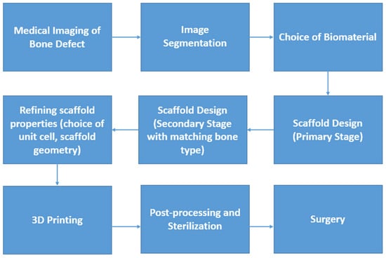
Figure 1.
Flowchart of manufacture and application of a 3DP customized bone scaffold.
CSDs (typically > 5 cm in diameter) or those defects that do not heal spontaneously during the lifetime of the patient require support in the form of biomaterial scaffolds [5,14,15,16,17]. Despite adequate stabilization, bone loss greater than twice the diameter of the long bone diaphysis may potentially result in non-union [15]. The current gold standard in the treatment of bone defects is autografts or autologous bone transplantation which contain a scaffold with osteogenic properties [15,16,17,18]. The limitations of autologous transplantation or autografts include limited harvesting, donor-site morbidity, unavailability of donor bone tissues, risk of infection, and mismatch between the bone geometry and the defect site [16,17,18]. Autografts often lack sufficient mechanical strength for load-bearing applications, necessitating the use of artificial scaffolds [19]. Porous metallic scaffolds mimic the structure of natural bone in addition to providing ample mechanical integrity; this makes it suitable for treatment of CSDs [19]. As far as load bearing applications are concerned, metal biomaterials, especially Ti and its alloys, Magnesium and its alloys, Cobalt-Chromium, Stainless Steel, etc., are popular [20]. Of the aforementioned biomaterials, Ti and its alloys are popular in 3DP BTE scaffold fabrication.
Other popular biomaterials include bioceramics such as hydroxyapatite (HAp), tricalcium phosphate (TCP), bioactive glasses, and natural polymers like gelatin, collagen, chitosan, poly-lactic-co-glycolic acid (PLGA), polycaprolactone (PCL), or composites such as silk fibroin (SF)/TCP, SF/Hap, etc. [20,21,22]. Of the inorganic non-degradable metal biomaterials in BTE and Ti and its alloys, especially Ti64, are the gold standard. Pure Ti, Ti64, Ti6-Al-7Nb, and Ti-35Nb-5Ta-7Zr are being used in a wide range of biomedical applications [21,22,23]. Its bioinert and biocompatible nature makes it suitable for long term scaffolds, which is needed in CSD treatment [22,23,24]. Degradable metals such as Iron (Fe) and its composites such as Fe-Mn (manganese), and Mg and its composites such as Mg-PLGA and Mg-TCP are currently being developed by researchers as degradable bone scaffolds.
Ti64 has demonstrated its biocompatibility and bio-inert nature, making it apposite for long-term application [25,26,27,28]. Ti64 has been widely used in dentistry and orthopedic applications such as dentures, hip, knee and other hard tissue scaffolds, maxillofacial and oral repair, cranioplasty, plates, screws, etc. [26,28]. Pore size and porosity play a critical role in promoting osteogenesis in 3D-printed scaffolds, with optimized architectures enhancing bone ingrowth and integration [29].
Ti64 was used in the current study due to its industrial, clinical, and regulatory acceptance. The current study incorporated lattices into the 3DP scaffold to optimize its performance by reducing stress shielding/elastic modulus mismatch and facilitating osseointegration. The Young’s modulus of an ideal bone replacement should be as close to that of the human bone as possible for effective load distribution. The type of lattice structure, pore size, porosity, pore interconnectivity was designed and evaluated for mechanical and biological optimization for bone replacement.
The objective is to create a scaffold/bone block with adequate osseointegration ability, mechanical strength, and a porous structure to facilitate bone ingrowth—through a novel comparative framework evaluating multiple lattice architectures and pore sizes under identical manufacturing and testing conditions. The novelty lies in the systematic, side-by-side comparison of diamond, gyroid, and cubic lattices across multiple pore sizes, fabricated under identical additive manufacturing conditions and subjected to both mechanical and biological evaluation. This unified benchmarking approach could offer practical insights for scaffold selection and optimization. The current work serves as a foundational experimental framework, with subsequent research including predictive models, which are currently in progress.
2. Materials and Methods
2.1. Feedstock Powder
The samples used for the current study were fabricated using gas-atomized Ti-6Al-4V extra-low interstitial (ELI) powder supplied by SLM Solutions, Lübeck, Germany (Nikon SLM Solutions AG 2024). The chemical composition of the powders as provided by the supplier is detailed in Table 1. The powder morphology was observed to be predominantly spherical (Figure 2).

Table 1.
Chemical composition of SLM Grade 23 Ti64 ELI [30].
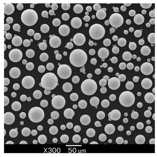
Figure 2.
Morphology of Ti64 particles (SEM).
2.2. Sample Design and Fabrication
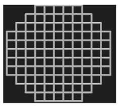
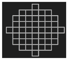
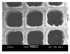
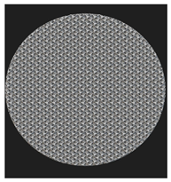
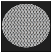
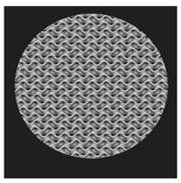
Cylindrical (⌀ 10 mm × h 20 mm) and disc (⌀ 10 mm × h 4 mm) samples were designed for the mechanical and biological tests, respectively. The cylindrical samples were designed as per the ASTM E9 standard (Compression Testing of Metallic Materials at Room Temperature) [31], which also satisfies the ISO 13314: 2011 standard [32] for compression testing of porous metal samples. The porous scaffolds were designed using nTopology version 3.29.3. Three different unit cells (diamond, cube, and TPMS gyroid) (Figure 3) with three different pore sizes (300, 600, and 900 μm) were designed.
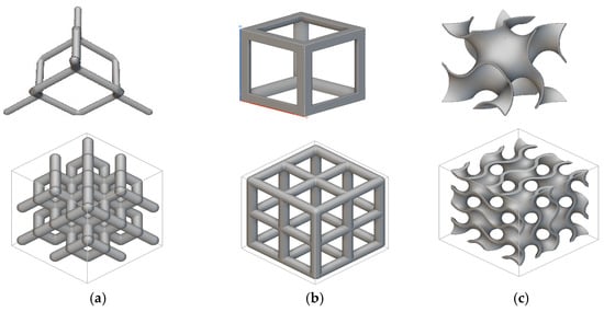
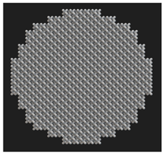
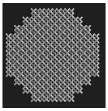
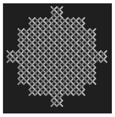
Figure 3.
Unit cells used in this study and the 2 × 2 × 2 lattices: (a) diamond, (b) cubic, and (c) gyroid.
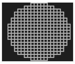
Figure 4a,b have depicted the CAD models (representative of 900 μm pore size) of the cylinders and discs used in this study.
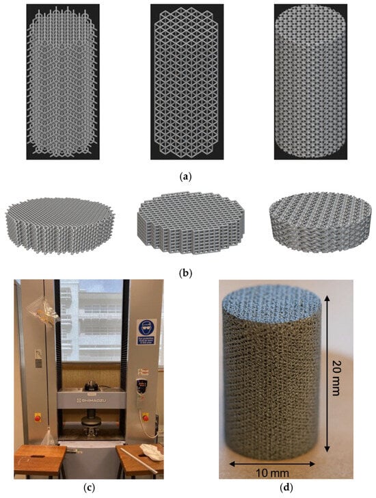
Figure 4.
(a) CAD models of cylinder samples (ϕ 10 mm × h 20 mm). (b) CAD models of disc samples (ϕ 10 mm × h 4 mm). (c) Mechanical testing setup. (d) Specimen geometry (gyroid sample).
Diamond and cube lattices are strut-based lattices and TPMS gyroid is a sheet-based lattice. The sheet thickness of the gyroid lattices were fixed at 100 μm. The sample scaffolds were fabricated using SLM 280 (Nikon SLM Solutions, Germany) located at Nikon SLM Solutions Pte Ltd., Singapore. The laser source is YLR-100-SM single-mode CW ytterbium fiber laser (1064–1100 nm). The process parameters used include a laser power of 200 W, laser scanning speed of 500 mm/s, layer thickness of 30 μm, and hatching thickness of 120 μm, resulting in an energy density of 111.11 J/mm3. Following the fabrication, the Ti64 samples were subjected to wire-cutting and washed with distilled water. This was followed by sterilization using ethanol.
2.3. Sample Characterization
The morphological characterization of the Ti64 scaffolds was conducted using dry-weighing, SEM imaging, and micro-CT (µCT) scanning. The surface morphology was characterized using the JEOL JSM-5600LV (JEOL Ltd., Tokyo, Japan). The pore and strut size were analyzed using SEM (scanning electron microscopy) and µCT. The porosity (by measuring relative density) was also measured using µCT and dry weighing.
2.3.1. Dry Weighing, µCT Scanning, and SEM
Dry weighing was conducted using the Mettler Toledo XS204 (Greifensee, Switzerland). The mass of the samples (n = 5) was thrice at room temperature and normal atmospheric conditions. The bulk density of Ti64 is 4430 kg/m3. The results obtained from the dry weighing was used for calculating the porosity. The pore size, strut size, and porosity were measured using the Skyscan 1173 MicroCT equipment (Bruker MicroCT: Kontich, Belgium) with a voltage of 130 kV and current of 60 μA. The morphological characterization is reported in Table 2, Table 3 and Table 4.
Table 2.
Sample Characterization of Diamond Samples.
Table 3.
Sample Characterization of Cubic Samples.
Table 4.
Sample Characterization of Gyroid Sample.
2.3.2. Mechanical Testing
The specimens (n = 5 as per ISO 13314) were tested in compression until failure to determine the mechanical properties. Compression tests were carried out using the Shimadzu Autograph AG-X Plus mechanical testing machine with a maximum loading cell of 100 kN. The ISO 13314:2011 (ductility testing—compression test for porous and cellular metals) was used. The ultimate compressive strength (UCS/σmax), yield strength (σy), and Young’s modulus (E) were obtained from the stress–strain curves. As per ISO 13314: 2011, UCS is the first maximum compressive strength [28]. The concept closest to Young’s modulus is the elastic gradient, which is the gradient of the elastic straight line between σ70 and σ20. It was noted that the plateau stress is equivalent to the yield stress, which was determined using the arithmetical mean of the stresses between 20% and 40% of the compressive strain [28]. The mechanical testing setup and specimen geometry (gyroid sample) are given in Figure 4c,d.
2.3.3. In Vitro Biological Evaluation
HOBs (human osteoblasts, 500,000, cryopreserved) were purchased from PromoCell (C-12720, Heidelberg, Germany). Human osteoblasts (HOBs) were selected due to their direct relevance to bone-contact surfaces in orthopedic applications. These cells are fully differentiated osteoblasts from femoral trabecular bone tissue of a healthy donor (37 years, Caucasian female). Cells were cultured using Osteoblast culture medium (PromoCell, Germany) supplemented with 10% supplement mix (PromoCell, Germany) and antibiotics (1% PenStrep, Gibco, Billings, MT, USA). The cells were cultured under standard conditions (5% CO2, 37 °C). Cell medium was refreshed every 3 days without disturbing the cell monolayer. Cell passage was carried out when cell confluency reached 80%. At each passage, cells were washed with phosphate-buffered saline (PBS, Gibco), detached with Trypsin EDTA (Gibco, USA) and plated in T25 cell culture flasks (Thermo Fisher Scientific, Waltham, MA, USA) at a density of 15,000 cells/cm2. Final cell densities were 2.5 × 10⁵ (low) and 1 × 10⁶ cells/mL (high). Osteoblasts were seeded onto scaffolds using drop method in a 24-well plate using 0.1 mL of cell solution. To permit cell attachment, the scaffolds were placed in an incubator for 2 h. This was followed by adding 2 mL of supplemented growth media.
Cell adherence using fluorescence microscopy was performed to understand the extent of osteoblast adherence on 3DP Ti64 scaffolds using 4′, 6-Diamidino-2-Phenylindole, Dihydrochloride (DAPI, 0.01 mg/mL in PBS) (Invitrogen, United States). Live cells were fixed using 4% paraformaldehyde (PFA); 2 mL of 4% PFA was added to the scaffolds at room temperature. The cell nuclei (stained in blue) were observed. The leachate analysis in the current study involved Ti64 scaffolds immersion in the cell culture medium followed by the seeding of HOBs to check for cytotoxicity. The cytotoxicity of the cells exposed to Ti64 for 14 days was assessed using DAPI+ fluorescence microscopy.
Cell proliferation was conducted using the MTT (3-(4,5-dimethylthiazol-2-yl)-2, 5-diphenyl-2H-tetrazolium bromide) Cell Proliferation and Cytotoxicity Assay Kit (MyBioSource, USA). The assay was conducted as per the manufacturer’s instructions and a 7-day end point was used. The optical density (OD) value was measured with a microplate reader at 570 nm. The color intensity is directly proportional to the number of viable cells and the rate of cell proliferation, with a darker color indicating greater cell proliferation and a lighter color indicating cytotoxicity [26].
2.4. Statistical Analysis
The data from the mechanical and biological tests were analyzed using Microsoft excel and SPSS Statistics 29.
3. Results and Discussion
3.1. Sample Characterization
Figure 5 depicts the CAD and measured porosity of the 3DP scaffolds.
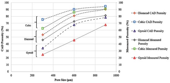
Figure 5.
CAD Porosity and Measured Porosity of Samples.
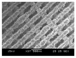
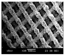
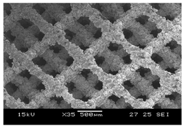
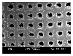
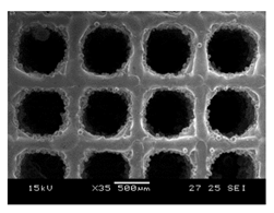
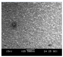
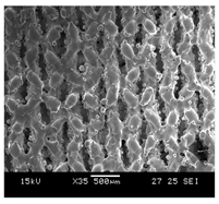
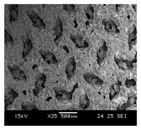
The difference in the porosity and pore size (as reported in Table 2, Table 3 and Table 4) of the designed and as-built samples could be due to the fusion of the powders and subsequent adhesion. The porosity of the as-built samples is lower than the designed samples in all the samples. The deviation of the measured porosity from the CAD porosity is predominant for the TPMS gyroid samples compared to the strut-based diamond and cubic samples. For the strut-based lattices, lower porosity samples deviated more from the CAD porosity. The measured pore sizes were consistently lower than the designed values. This could be due to factors like powder adhesion and partial melting during printing.
For diamond and cubic lattices with designed pore sizes of 300, 600, and 900 μm, the measured pore sizes (using μCT and SEM) ranged from approximately 228 μm to 846 μm. In gyroid lattices, the P300 sample was non-porous, while the measured pore sizes for P600 and P900 were 358 μm and 630 μm, respectively, indicating greater deviation at smaller scales due to the complexity of TPMS geometries. The observed deviation between the designed and measured porosity and pore size in gyroid scaffolds can be attributed to the complex, continuously curved geometry of TPMS structures. Unlike strut-based lattices, gyroid surfaces are more prone to partial melting, powder adhesion, and feature resolution loss during fabrication. These effects can lead to localized pore occlusion, resulting in a lower actual porosity than predicted by the CAD model. This phenomenon was also evident in the SEM images obtained from the printed samples.
3.2. Compressive Properties
Table 5 presents the relevant data from the sample compression tests.
Table 5.
Mechanical Characterization of the 3DP Ti64 samples from Compression tests (n = 5).
During compression testing of D300 samples, shear occurred in all five samples. The D300 (porosity < 50%) and D600 (porosity > 50%) were suitable for cortical bone applications. Unlike the former, the latter is not suitable for high-load-bearing applications such as in the diaphysis region or distal region of the femur. The D900 (with porosity > 50%) sample is closer to the range of the trabecular bone’s modulus and can be considered for non-load bearing scaffolds. This asserts the importance of pore size in reducing the elastic modulus mismatch and stress-shielding for bone scaffolds. Similar trends were also noted for the UCS and σy. A bone scaffold biomaterial should have high yield strength and fatigue strength to prevent failure under cyclic loading; hence apposite yield strength is necessary. The representative stress–strain curves from the compression testing are given in Figure 6a–c. The images of failure modes of all the samples are given in the Supplemental File (Section S2).
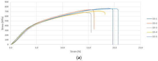
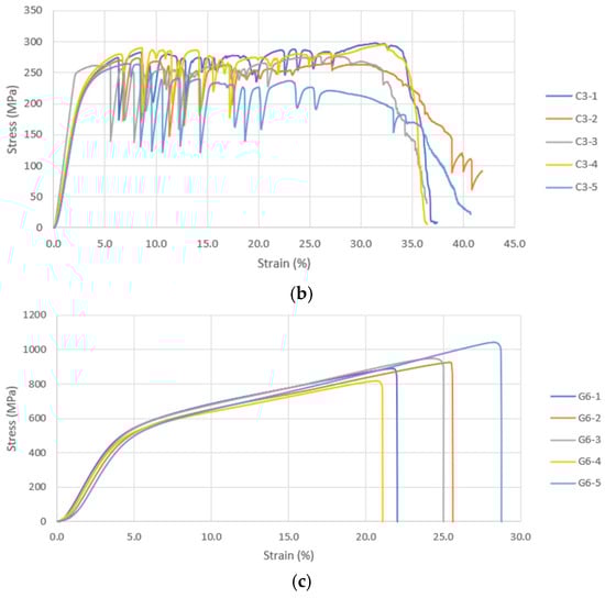
Figure 6.
(a) Compressive Stress–Strain Curves for Diamond 300 Scaffold. (b) Compressive Stress–Strain Curves for Cubic 300 Scaffold. (c) Compressive Stress–Strain Curves for Gyroid 600 Scaffold.
As per the findings of Taniguchi et al. (2015) [33], pore size had significant impact on the biological and compressive properties of 3DP commercially pure Ti diamond lattices. Similar to the current study, the samples of 300, 600, and 900 μm pore size were subjected to mechanical testing and E in the range of cancellous bone was reported. Contradictory to the results of the current study, although all scaffolds had the same porosity (65%), the increase in pore size led to a ~10% increase in yield strength and a ~45% increase in elastic modulus. This could be because the scaffolds were designed for a fixed porosity and an increase in pore size could have been compensated by increase in strut size. The results reported by Huang et al. (2022) [34] were similar to the current study. Table 6 has compared the findings of our study and similar studies [33,35,36,37,38,39]. It has to be noted that as the strut size in our study was constant, an increase in pore size would mean an increase in porosity.
Table 6.
Comparison of the findings of the current study and similar studies (diamond unit cell).
Similar to the diamond samples, the lower pore sizes exhibited maximum modulus, yield strength, and UCS in cubic samples. The C300 sample experienced failure by means of bending with potentially vertical strut failure being the reason for deformation. The C600 and C900 samples failed due to crushing. When a strut fails, the neighboring struts in the same plane are also subjected to failure, which is a cascading phenomenon. The E for samples decreases with increasing pore size and porosity. It has to be noted that similar to the diamond samples, the cubic samples also experienced sharp decline in E on increasing the pore size from 300 to 600 μm. However, the C300 and 600 samples (>50% porosity) had a modulus within the cortical bone range, making it suitable for load-bearing applications. The C900 sample modulus is very slightly above the trabecular range; however, it can be used in regions where there the proportion of trabecular bone is higher than cortical bone.
Similar to the diamond samples, the C300 samples exhibited a yield stress greater than cortical bone, whereas the 600 (cortical) and 900 (trabecular) μm samples were within the bone range. Results similar to the current study were reported by Choy et al. (2017) [41]. Choy et al. (2017) [41] reported that 3DP cubic samples of different strut sizes failed in a layer-by-layer manner. The method of collapse was the same, irrespective of the strut sizes. A number of research studies [42,43,44,45,46,47,48,49,50,51,52,53,54,55,56,57,58,59,60] have demonstrated how the change in pore size and porosity affects the mechanical properties. Benedetti et al. (2019) [57] also reported similar results. All the aforementioned research studies have detailed how an increase in porosity and pore size compromises the mechanical integrity. Table 7 lists the summary data of the current study and other related studies using cubic unit cell samples.
Table 7.
Summary data of current study vs. other similar studies (cubic unit cell).
As far as the TPMS gyroid samples are concerned, only data pertaining to G600 and G900 were considered; G300 samples were not porous and hence their mechanical data have not been discussed. As detailed in 3.1, localized pore occlusion from the partial melting of powders may have resulted in the non-porosity of gyroid samples. The gyroid samples in the current study are not suitable for trabecular bone applications. Similar to D300, the G600 sample fractured by means of shear. The G900 sample also experienced failure due to shear; in addition, it is the only sample that exhibited failure before 20% compressive strain. The study by Bobbert et al. (2017) [57] on the compressive performance of four types of TPMS structures (primitive (P), I-WP (I), gyroid (G), and diamond (D)) found that an increase in the pore size resulted in a reduction in E.
Similar deformation behaviors were reported previously by Weiβmann et al. (2016) [61], Van Hooreweder et al. (2017) [62], and Zhang et al. (2018) [29]. Similar to the current study, a failure in the oblique direction was observed by Sun et al. (2022) [63]. Sun et al. (2022) [63] further reported quasi-cleavage to be the cause of fracture of the gyroid samples. Similar to our current study and other studies reviewed, a decrease in pore size was associated with greater mechanical integrity with respect to E, yield, and UCS.
A similar research study by Yanez et al. (2018) [64] recommended gyroid Ti64 as a scaffold in bone defect construction. Wang et al. (2022) [59] evaluated the biomechanical properties of cubic, octet, and TPMS gyroid Ti64 structures. Wang et al. (2022) [59] found that cubic lattices were less stable compared to octet and TPMS gyroid. Similar to our study, the TPMS gyroid structures reported higher mechanical integrity for similar porosities. Unlike the porosity range of 38–59% used by Wang et al. (2022) [59], our G600 and G900 samples in the current study had a porosity of <50%.
Wang et al. (2022) [59] has reported TPMS gyroid samples to have exhibited maximum stability due to the homogenous distribution of stress within the structure. Similar to our study, the TPMS gyroid samples were least affected by the variation in porosity. As expected, our TPMS gyroid samples had a higher mechanical performance despite the larger pore sizes. Wang et al. (2022) [59] has also reported that gyroid structures had a higher E (1.85 times) compared to the cubic samples at similar porosity (~50%). With a higher porosity, the E of TPMS was 4.5 times higher.
A similar study conducted by Naghavi et al. (2022) [65] compared the mechanical characteristics of TPMS diamond and gyroid Ti64 structures for bone implants. Similar to our samples design, the pore size was varied with fixed sheet thickness. However, the intra-group variation of pore sizes was not uniform. Similar to our study, the increase in pore size reduced the E and σy of the gyroid structures. The trend was similar for TPMS diamond samples as well. Naghavi et al. (2022) [65] reported that the stiffness of the gyroid structures varied from 4.4–9.54 GPa and σy had a range of 106–170 MPa. As far as the diamond samples are concerned, the scaffolds were stiffer at similar pore sizes and porosities. Barber et al. (2021) [66] aimed at comparing the TPMS gyroid and diamond with a constant porosity of 75%. They demonstrated that gyroid had a stiffness of 2.3 GPa and σy of 94 MPa. The TPMS diamond samples had a stiffness and σy of 3.1 GPa and 129 MPa, respectively.
Bobbert et al. (2017) [60] reported similar results for compression testing of TPMS structures. The compressive performance of four types of TPMS structures (primitive (P), I-WP (I), gyroid (G), and diamond (D)) with different porosities and pore sizes and reported similar trends in mechanical properties. Sun et al. (2022) [63] compared the compression and energy absorption properties of SLM Ti64 TPMS structures and reported an elastic–brittle failure mechanism. Yanez et al. (2018) [64] studied gyroid scaffolds in the range of 75–90% porosity in the trabecular bone range with spherical structures (normal) and ellipsoidal structures (deformed), respectively. It was reported that deformed gyroid structures reported higher compressive properties compared to normal gyroid structures of similar porosity.
A similar study by Zaharin et al. (2018) [55] compared the cube and gyroid lattices of varying strut sizes/sheet thickness and reported a linear decrease in the compressive modulus with an increase in the porosity and pore size. A strut diameter of 0.3 mm was recommended for bone scaffold applications. The study conducted by Li et al. (2019) [67] investigated the early osseointegration in porous Ti64 samples with TPMS unit cell and reported satisfactory results. On compressive testing, the samples reported a satisfactory compressive modulus and porosity well within the range of the cortical bone. Table 8 lists the summary data of the current study and other related studies [55,57,60,64,65] using gyroid unit cell samples. The current results show a similar trend in the mechanical properties.
Table 8.
Summary of data of current study vs. other similar studies.
3.3. Biological Performance of 3DP Ti64 Scaffolds
The biological performance of the 3DP Ti64 scaffolds was explored using the static cell culture and biochemical assays. The cytocompatibility, cell adherence, and proliferation has been assessed by means of fluorescence microscopy and MTT assay.
3.3.1. Cytocompatibility Assessment
HOBs were exposed to cell medium with Ti64 and to cell medium without Ti64 (control) for a period of 14 days. On comparing the morphology and number of cells in the control with the cells exposed to Ti64, it was found that the HOBs in the Ti64 leachate exhibited similar nuclei morphology compared to the control as depicted in Figure 5. In addition, the cells proliferated in the leachate medium. This further reiterates the cytocompatibility of Ti64, which is FDA approved for biomedical applications. A number of research studies have substantiated the cytocompatibility of Ti64 using osteoblasts. The study conducted by Huang et al. (2021) [34] studied the cytocompatibility of Ti64 by evaluating the scaffold degradation using indirect cytotoxicity and an ion release test. It was noted that there was an increase in cell proliferation on day 14 compared to day 7.
3.3.2. Impact of Pore Size on Cell Adherence and Cell Proliferation
Initial cell attachment on the scaffold surface is essential for scaffold–bone bonding. The scaffold surface must be conducive to facilitate the osseointegration. As depicted in Figure 7, D300, C300 and G300 had more cells compared to their higher pore size counterparts.
Figure 7.
Cell adherence using fluorescent imaging (magnification: 4×).
The number of cells on the surface decreased with an increase in pore size. It can be observed that initial cell adherence exhibited the following trend:
D300 > C300 > G300
A similar trend was followed by the 600 μm pore size group. However for the 900 μm pore size group, C900 had the maximum adherence followed by D900 and G900. It was observed that pore size was inversely proportional to cell adherence. It has to be noted that these differences could be due to variations of surface curvature, pore architecture, and microtopography that could impact both short-term cell attachment versus longer-term cell proliferation. The study by Nune et al. (2016) [68] studied the behavior of osteoblasts on functionally graded 3DP Ti64 mesh structures. Similar to the results of the current study, Ti64 meshes had well-distributed and well-spread nuclei. Nune et al. (2016) [68] reported that non-porous Ti64 exhibited a uniform distribution of cell nuclei whereas porous samples exhibited cell attachment on the struts and curved regions of the struts. This is similar to our findings.
A smaller pore size provides larger surface area for cells to interact, thereby producing more interfacial force prior to falling through the pores. Hence, smaller pore sizes are expected to have more surface attachment of cells. This could be reason for more cells to be found on the surface of D300, C300, and G300. The diamond group had maximum cell adherence in the 300 and 600 group whereas the C900 reported superior adherence in the 900 μm group. It has to be noted that cell adhesion is the first cellular event when osteoblasts contact a scaffold surface. According to Xu et al. (2016) [69], cell adhesion impacts the proliferation, tissue formation, and differentiation. As reported by Van Bael et al. (2012) [70], cell seeding efficiency indicative of cell adherence (on day 1) was significantly higher in the smallest pore size.
Though cell proliferation can be qualitatively assessed by means of fluorescent imaging using DAPI, quantitative assessment of cell proliferation mandates using MTT or similar assays. The MTT assay was performed in the current study to investigate the impact of varying the pore sizes and geometry. Figure 8 has depicted the results of the cell proliferation using the MTT assay.
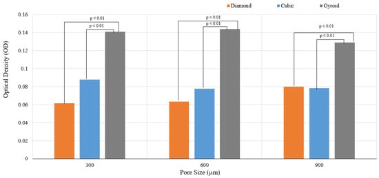
Figure 8.
Results of cell proliferation at 7 days (p < 0.01).
It can be observed that both pore size and unit cell variation had an impact on the cell proliferation. The cell proliferation over 7 days was reported maximum for gyroid with the following trend:
G600 > G300 > G900
A statistically significant difference in the cell proliferation was reported between the diamond/gyroid and cubic/gyroid groups. Cell proliferation in both the strut-based lattices did not show any statistically significant difference; however, the sheet-based TPMS gyroid had substantially higher cell proliferation. The higher cell proliferation on G600 could be due to a balance between the pore size and surface adherence. It has to be noted that the actual pore sizes of the G600 and G900 samples are 423 ± 12.5 μm and 710 ± 6.8 μm, respectively. The TPMS gyroid structures are characterized by high permeability in addition to a slick and uniform surface. It is known for its absence of sharp corners, high surface area, and highly interconnected network and zero mean curvatures. It has to be noted that the mean surface curvature of the cancellous bone is close to zero; this promotes cell proliferation and tissue regeneration on such scaffolds. This could be one of the key reasons for the increased cell proliferation on the gyroid scaffolds.
It has to be noted that the variation in the surface curvature may potentially lead to substantial changes in terms of the cell attachment rate, cell migration speed, and cell morphology, including the cell spread area. Results similar to our study were reported by Wang et al. (2022) [59], who observed that the cell viability of TPMS gyroid Ti64 was greater than the octet and cubic lattice structures. Wang et al. explored the relationship between ion release and the type of lattice structure. Though we have not explored ion release, the aspect of cell viability is considered. It has to be noted that the scaffold surface area of the TPMS gyroid samples in the current study was higher than the cubic and diamond samples; this could also be one of the reasons for superior cell proliferation. The sharp struts and edges and acute corners of diamond and cubic structures may have limited the cell proliferation. Amongst the diamond and cubic samples, the following trend was observed for cell proliferation:
C300 > D900 > C900 > C600 > D600 > D300
The overall trend is as follows:
G600 > G300 > G900 > C300 > D900 > C900 > C600 > D600 > D300
As far as the diamond samples are concerned, D900 resulted in max cell proliferation. This contradicts the findings of Taniguchi et al. (2016) [33]. This could be because the cell proliferation was taken over 7 days; an extended period of MTT assessment with data points at 14, 21, and 28 days could substantiate the long-term cell proliferation. The study conducted by Taniguchi et al. (2016) [33] investigated the impact of pore size on bone ingrowth into porous Ti64 samples. Amongst the diamond lattice samples designed for pore sizes of 300, 600, and 900 μm with a constant porosity of 65%, it was noted that the 600 μm sample (P600) exhibited maximum bone ingrowth at 2 weeks; this was followed by P900 and P300. The current study is based on results of in vitro testing and may not substantiate in vivo performance. The study conducted by Ran et al. (2018) [71] reported that cell seeding efficiency was highest for samples of 500 μm pore size (p500) followed by p700 and p900; there was a statistically significant difference between the cell seeding efficiency amongst different pore sizes. As expected, the cell seeding efficiency decreased with increasing pore size.
Ran et al. (2018) [71] also reported that cell proliferation increased with an increasing duration of seeding (7 days vs. 14 days). At the end of 7 days, the cells on p700 exhibited a higher viability whereas p900 exhibited a higher proliferation compared to p500 over 14 days of culture. Markhoff et al. (2015) [51] recommended a pore size of 400–620 µm and a porosity of 76% for maximum metabolic activity. According to Markhoff et al. (2015) [51], initial cell adhesion and cell bridging can be facilitated with lower pore sizes as they have a higher surface area, thereby leading to increased cell proliferation. Mechanical stiffness may also have an impact on the metabolic activity as osteoblasts are mechano-sensitive [51]. However, lower pore sizes may limit the cell migration or lead to cell occlusion. As cells were reported to have been adhering to struts due to the surface area for initial adhesion, it is important to cater to apt strut and pore sizes.
The C300 samples facilitated initial cell adherence and proliferation and reported high cell numbers for the 7-day culture. The cells may not have had ample time for permeating into the pores and spreading on the internal regions of the scaffolds. It is imperative to conduct the cell proliferation over different time points to understand the impact of the pore size and the unit cell variation. However, the TPMS gyroid is superior to the strut-based lattices used in this study. In addition, the impact of pore size variation did not have statistical significance unlike the variation in unit cell.
Larger pore sizes can enhance vascularization and lead to enhanced osseointegration. However, smaller pores in the range of 400–600 μm facilitate early cell adherence due to focal adhesion [51]. The minimal pore size to stimulate bone ingrowth is 100–150 μm [70,71,72,73,74]. Pore sizes larger than 300 μm are capable of augmenting the capillary and new bone formation [70,71,72,73,74]. Pore sizes larger than 900 μm may limit the cell-bridging ability. Smaller pore sizes have more surface area for more tissue to form; this could be the reason the 300 μm pore sizes have initial cell adherence [71,72,73,74,75]. The 150–900 μm pores permit the diffusion of waste and nutrients.
As far as porosity is concerned, a porosity in the range of 40–70% is ideal for the regulation of cell motility and nutrient and oxygen delivery [29]. In our study certain samples exhibited a porosity of >50%, which is in the range of the cancellous bone. This is ideal for cell proliferation and adherence. However, this could be the reason for the compromised mechanical performance. An apposite balance between the biological and mechanical properties of a bone scaffold is necessary for facilitating osseointegration.
4. Conclusions
This study demonstrated that increasing the pore size of Ti64 scaffolds—while keeping strut size constant—significantly increased porosity, which in turn reduced the elastic modulus (E), yield strength (σy), and ultimate compressive strength (UCS). Among the diamond structures, D300 and D600 exhibited mechanical properties within the range of cortical bone, whereas D900 approached the upper limit of trabecular bone modulus. However, D600 may not be ideal for high-load-bearing regions, such as the femur or tibia. Cubic structures with 300 μm and 600 μm pores also achieved moduli within the cortical bone range, combined with high porosity (>50%), potentially enhancing osteoblast adhesion. Although C900 slightly exceeded the trabecular modulus, it may still be suitable for regions dominated by trabecular bone. Notably, failure in C600 and C900 occurred via vertical strut crushing. Gyroid samples G600 and G900 aligned well with cortical bone properties in terms of E and σy but were not deemed suitable for trabecular bone applications.
Biocompatibility was confirmed through leachate analysis, with no adverse effects on osteoblast nuclei morphology as observed in DAPI-stained fluorescence images. Interestingly, D300, C300, and G300 samples showed higher cell attachment than their higher pore-size counterparts, though the gyroid group exhibited the highest proliferation overall. The optimal pore size range of 300–900 μm supported favorable biological outcomes. These differences could also be attributed to the distinct roles that surface curvature, pore architecture, and microtopography play in influencing short-term cell attachment versus longer-term cell proliferation. Additionally, variations in cell retention during washing steps in the adherence assay may have contributed to these discrepancies.
Overall, both mechanical performance and cytocompatibility were influenced by pore size and lattice geometry. Further investigations are needed to validate long-term in vivo performance and to refine scaffold designs for specific anatomical applications.
5. Limitations and Future Work
The current study has provided valuable insights into the mechanical and biological performance of Ti64 lattice scaffolds; however, some of the study limitations must be acknowledged. The mechanical tests are solely based on compression; however, there is a need to explore tensile and fatigue tests for orthopedic scaffolds. The biological performance was assessed using MTT assay; however, there is a need to understand mineralization and differentiation. This calls for the use of other in vitro assays. Nuclei counting per unit area or fluorescence intensity measurement was not performed, limiting the ability to objectively compare cell proliferation. There is also a need to quantify cell distribution, osteogenic differentiation, and mineralization. Only short-term adhesion and proliferation studies were conducted, and there is a need to conduct long-term studies for an appropriate understanding of biological performance. Also, there is a need for more controlled quantification and validation pertaining to biological and mechanical testing. Future studies could facilitate the integrated study of mechanobiological performance to understand the osseointegration ability of bone scaffolds. Tensile and fatigue testing could also be useful to comprehend the mechanical performance of bone scaffolds for bone replacement. Future studies could also explore different lattices and pore architecture to optimize the mechanical and biological performance. There is also a need to tune the SLM laser parameters due to the sensitivity of mechanical and biological performance to energy input during selective laser melting.
Supplementary Materials
The following supporting information can be downloaded at https://www.mdpi.com/article/10.3390/pr13061827/s1: Section S1: Calculation of Yield Stress; Section S2: Representative images of Sample Failure modes.
Author Contributions
Conceptualization, P.N., S.M.C. and W.Y.Y.; Methodology, P.N., S.M.C. and W.Y.Y.; Software, P.N., S.M.C. and W.Y.Y.; Validation, P.N., S.M.C. and W.Y.Y.; Formal Analysis, P.N., S.M.C. and W.Y.Y.; Investigation, P.N., S.M.C. and W.Y.Y.; Resources, P.N., S.M.C. and W.Y.Y.; Data Curation, P.N., S.M.C. and W.Y.Y.; Writing—Original Draft Preparation, P.N., S.M.C. and W.Y.Y.; Writing—Review and Editing, P.N., S.M.C. and W.Y.Y.; Visualization, P.N., S.M.C. and W.Y.Y.; Supervision, P.N., S.M.C. and W.Y.Y.; Project Administration, P.N., S.M.C. and W.Y.Y.; Funding Acquisition, P.N., S.M.C. and W.Y.Y. All authors have read and agreed to the published version of the manuscript.
Funding
This study is partially funded by the National Additive Manufacturing Innovation Cluster (NAMIC) (Grant ID M22N2K0011), Agency for Science, Technology and Research (A*STAR), Singapore.
Data Availability Statement
Data available on request due to restrictions on privacy.
Acknowledgments
The authors would like to thank Nikon SLM Solutions Pte Ltd., Singapore, for their research collaboration and support for sample fabrication.
Conflicts of Interest
The authors declare no conflicts of interest.
Abbreviations
The following abbreviations are used in this manuscript:
| AM | Additive manufacturing |
| BTE | Bone tissue engineering |
| 3DP | 3D printing |
| CSD | Critical-sized bone defects |
| ELI | Extra-low interstitial |
| µCT | MicroCT |
| UCS | Ultimate compressive strength |
| HOB | Human osteoblast |
| PBS | Phosphate-buffered saline |
| DAPI | 4′, 6-Diamidino-2-Phenylindole, Dihydrochloride |
| MTT | 3-(4,5-dimethylthiazol-2-yl)-2,5-diphenyl-2H-tetrazolium bromide |
| OD | Optical density |
| C | Cubic |
| TC | Truncated cube |
| TCO | Truncated cuboctahedron |
| RD | Rhombic dodecahedron |
| D | Diamond |
| RCO | rhombi cuboctahedron |
| S | Star |
| X | Cross |
| P | Primitive |
| I | I-WP |
| G | Gyroid |
References
- Popov, V.V.; Muller-Kamskii, G.; Kovalevsky, A.; Dzhenzhera, G.; Strokin, E.; Kolomiets, A.; Ramon, J. Design and 3D-printing of titanium bone implants: Brief review of approach and clinical cases. Biomed. Eng. Lett. 2018, 8, 337–344. [Google Scholar] [CrossRef] [PubMed]
- Ngo, T.D.; Kashani, A.; Imbalzano, G.; Nguyen, K.T.; Hui, D. Additive manufacturing (3D printing): A review of materials, methods, applications and challenges. Compos. Part B Eng. 2018, 143, 172–196. [Google Scholar] [CrossRef]
- Ghorbani, F.; Li, D.; Ni, S.; Zhou, Y.; Yu, B. 3D printing of acellular scaffolds for bone defect regeneration: A review. Mater. Today Commun. 2020, 22, 100979. [Google Scholar] [CrossRef]
- Haleem, A.; Javaid, M.; Khan, R.H.; Suman, R. 3D printing applications in bone tissue engineering. J. Clin. Orthop. Trauma 2020, 11, S118–S124. [Google Scholar] [CrossRef]
- Nauth, A.; Schemitsch, E.; Norris, B.; Nollin, Z.; Watson, J.T. Critical-Size Bone Defects: Is There a Consensus for Diagnosis and Treatment? J. Orthop. Trauma 2018, 32, S7–S11. [Google Scholar] [CrossRef] [PubMed]
- Koolen, M.; Amin Yavari, S.; Lietaert, K.; Wauthle, R.; Zadpoor, A.A.; Weinans, H. Bone Regeneration in Critical-Sized Bone Defects Treated with Additively Manufactured Porous Metallic Biomaterials: The Effects of Inelastic Mechanical Properties. Materials 2020, 13, 1992. [Google Scholar] [CrossRef]
- Li, G.; Wang, L.; Pan, W.; Yang, F.; Jiang, W.; Wu, X.; Kong, X.; Dai, K.; Hao, Y. In vitro and in vivo study of additive manufactured porous Ti6Al4V scaffolds for repairing bone defects. Sci. Rep. 2016, 6, 34072. [Google Scholar] [CrossRef]
- Putra, N.E.; Mirzaali, M.J.; Apachitei, I.; Zhou, J.; Zadpoor, A.A. Multi-material additive manufacturing technologies for Ti-, Mg-, and Fe-based biomaterials for bone substitution. Acta Biomater. 2020, 109, 1–20. [Google Scholar] [CrossRef]
- Qiao, S.; Wu, D.; Li, Z.; Zhu, Y.; Zhan, F.; Lai, H.; Gu, Y. The combination of multi-functional ingredients-loaded hydrogels and three-dimensional printed porous titanium alloys for infective bone defect treatment. J. Tissue Eng. 2020, 11, 2041731420965797. [Google Scholar] [CrossRef]
- Tumedei, M.; Savadori, P.; Del Fabbro, M. Synthetic Blocks for Bone Regeneration: A Systematic Review and Meta-Analysis. Int. J. Mol. Sci. 2019, 20, 4221. [Google Scholar] [CrossRef]
- Noordin, N.N.F.N.M.; Ahmad, N.; Mariatti, M.; Yahaya, B.H.; Sulaiman, A.R.; Hamid, Z.A.A. A review on bioceramics scaffolds for bone defect in different types of animal models: HA and β-TCP. Biomed. Phys. Eng. Express 2022, 8, 052002. [Google Scholar]
- Rupp, M.; Klute, L.; Baertl, S.; Walter, N.; Mannala, G.K.; Frank, L.; Pfeifer, C.; Alt, V.; Kerschbaum, M. The clinical use of bone graft substitutes in orthopedic surgery in Germany—A 10-years survey from 2008 to 2018 of 1,090,167 surgical interventions. J. Biomed. Mater. Res. Part B Appl. Biomater. 2022, 110, 350–357. [Google Scholar] [CrossRef] [PubMed]
- Ji, K.; Wang, Y.; Wei, Q.; Zhang, K.; Jiang, A.; Rao, Y.; Cai, X. Application of 3D printing technology in bone tissue engineering. Bio-Des. Manuf. 2018, 1, 203–210. [Google Scholar] [CrossRef]
- Bose, S.; Vahabzadeh, S.; Bandyopadhyay, A. Bone tissue engineering using 3D printing. Mater. Today 2013, 16, 496–504. [Google Scholar] [CrossRef]
- Gao, C.; Wang, C.; Jin, H.; Wang, Z.; Li, Z.; Shi, C.; Wang, J. Additive manufacturing technique-designed metallic porous implants for clinical application in orthopaedics. RSC Adv. 2018, 8, 25210. [Google Scholar] [CrossRef]
- Giannitelli, S.M.; Accoto, D.; Trombetta, M.; Rainer, A. Current trends in the design of scaffolds for computer-aided tissue engineering. Acta Biomater 2014, 10, 580. [Google Scholar] [CrossRef]
- Zhang, L.; Yang, G.; Johnson, B.N.; Jia, X. Three-dimensional (3D) printed scaffold and material selection for bone repair. Acta Biomater. 2019, 84, 16. [Google Scholar] [CrossRef]
- Kanwar, S.; Vijayavenkataraman, S. Design of 3D printed scaffolds for bone tissue engineering: A review. Bioprinting 2021, 24, e00167. [Google Scholar] [CrossRef]
- El-Hajje, A.; Kolos, E.C.; Wang, J.K.; Maleksaeedi, S.; He, Z.; Wiria, F.E.; Choong, C.; Ruys, A.J. Physical and mechanical characterisation of 3D-printed porous titanium for biomedical applications. J. Mater. Sci. Mater. Med. 2014, 25, 2471–2480. [Google Scholar] [CrossRef]
- Sun, J.; Yang, Y.; Wang, D. Mechanical properties of a Ti6Al4V porous structure produced by selective laser melting. Mater. Des. 2013, 49, 545–552. [Google Scholar] [CrossRef]
- Yuan, L.; Ding, S.; Wen, C. Additive manufacturing technology for porous metal implant applications and triple minimal surface structures: A review. Bioactive Mater. 2019, 4, 56–70. [Google Scholar] [CrossRef]
- Ni, J.; Ling, H.; Zhang, S.; Wang, Z.; Peng, Z.; Benyshek, C.; Zan, R.; Miri, A.K.; Li, Z.; Zhang, X.; et al. Three-dimensional printing of metals for biomedical applications. Mater. Today Bio 2019, 3, 100024. [Google Scholar] [CrossRef] [PubMed]
- Ahsan, M.M.; Student, M.S. 3D printing and titanium alloys: A paper review. Eur. Acad. Res 2016, 3, 11144–11154. [Google Scholar]
- Dziaduszewska, M.; Zieliński, A. Structural and material determinants influencing the behavior of porous Ti and its alloys made by additive manufacturing techniques for biomedical applications. Materials 2021, 14, 712. [Google Scholar] [CrossRef]
- Wubneh, A.; Tsekoura, E.K.; Ayranci, C.; Uludağ, H. Current state of fabrication technologies and materials for bone tissue engineering. Acta Biomater. 2018, 80, 1–30. [Google Scholar] [CrossRef]
- Jariwala, S.H.; Lewis, G.S.; Bushman, Z.J.; Adair, J.H.; Donahue, H.J. 3D printing of personalized artificial bone scaffolds. 3D Print. Addit. Manuf. 2015, 2, 56–64. [Google Scholar] [CrossRef]
- Brunello, G.; Sivolella, S.; Meneghello, R.; Ferroni, L.; Gardin, C.; Piattelli, A.; Zavan, B.; Bressan, E. Powder-based 3D printing for bone tissue engineering. Biotechnol. Adv. 2016, 34, 740. [Google Scholar] [CrossRef] [PubMed]
- Germaini, M.M.; Belhabib, S.; Guessasma, S.; Deterre, R.; Corre, P.; Weiss, P. Additive manufacturing of biomaterials for bone tissue engineering–A critical review of the state of the art and new concepts. Prog. Mater. Sci. 2022, 130, 100963. [Google Scholar] [CrossRef]
- Zhang, Y.; Sun, N.; Zhu, M.; Qiu, Q.; Zhao, P.; Zheng, C.; Lu, T. The contribution of pore size and porosity of 3D printed porous titanium scaffolds to osteogenesis. Biomater. Adv. 2022, 133, 112651. [Google Scholar] [CrossRef]
- Nikon SLM Solutions, A.G. Ti6Al4V Grade 23 ELI Datasheet; Nikon SLM Solutions AG: Lübeck, Germany, 2024. [Google Scholar]
- ASTM E9-19; Standard Test Methods of Compression Testing of Metallic Materials at Room Temperature. ASTM International: West Conshohocken, PA, USA, 2019.
- ISO 13314:2011; Mechanical Testing of Metals—Ductility Testing—Compression Test for Porous and Cellular Metals. International Organization for Standardization: Geneva, Switzerland, 2011.
- Taniguchi, N.; Fujibayashi, S.; Takemoto, M.; Sasaki, K.; Otsuki, B.; Nakamura, T.; Matsushita, T.; Kokubo, T.; Matsuda, S. Effect of pore size on bone ingrowth into porous titanium implants fabricated by additive manufacturing: An in vivo experiment. Mater. Sci. Eng. C 2016, 59, 690–701. [Google Scholar] [CrossRef]
- Huang, G.; Pan, S.T.; Qiu, J.X. The osteogenic effects of porous tantalum and titanium alloy scaffolds with different unit cell structure. Colloids Surf. B Biointerfaces 2022, 210, 112229. [Google Scholar] [CrossRef] [PubMed]
- Pei, X.; Zhang, B.; Fan, Y.; Zhu, X.; Sun, Y.; Wang, Q.; Zhang, X.; Zhou, C. Bionic mechanical design of titanium bone tissue implants and 3D printing manufacture. Mater. Lett. 2017, 208, 133–137. [Google Scholar] [CrossRef]
- Zhang, B.; Pei, X.; Zhou, C.; Fan, Y.; Jiang, Q.; Ronca, A.; D’Amora, U.; Chen, Y.; Li, H.; Sun, Y.; et al. The biomimetic design and 3D printing of customized mechanical properties porous Ti6Al4V scaffold for load-bearing bone reconstruction. Mater. Des. 2018, 152, 30–39. [Google Scholar] [CrossRef]
- Yavari, S.A.; Ahmadi, S.M.; Wauthle, R.; Pouran, B.; Schrooten, J.; Weinans, H.; Zadpoor, A.A. Relationship between unit cell type and porosity and the fatigue behavior of selective laser melted meta-biomaterials. J. Mech. Behav. Biomed. Mater. 2015, 43, 91–100. [Google Scholar] [CrossRef] [PubMed]
- Liu, F.; Zhang, D.Z.; Zhang, P.; Zhao, M.; Jafar, S. Mechanical properties of optimized diamond lattice structure for bone scaffolds fabricated via selective laser melting. Materials 2018, 11, 374. [Google Scholar] [CrossRef]
- Wally, Z.J.; Haque, A.M.; Feteira, A.; Claeyssens, F.; Goodall, R.; Reilly, G.C. Selective laser melting processed Ti6Al4V lattices with graded porosities for dental applications. J. Mech. Behav. Biomed. Mater. 2019, 90, 20–29. [Google Scholar] [CrossRef]
- Deng, F.; Liu, L.; Li, Z.; Liu, J. 3D printed Ti6Al4V bone scaffolds with different pore structure effects on bone ingrowth. J. Biol. Eng. 2021, 15, 4. [Google Scholar] [CrossRef]
- Choy, S.Y.; Sun, C.N.; Leong, K.F.; Wei, J. Compressive properties of Ti-6Al-4V lattice structures fabricated by selective laser melting: Design, orientation and density. Addit. Manuf. 2017, 16, 213–224. [Google Scholar] [CrossRef]
- Martinez-Marquez, D.; Delmar, Y.; Sun, S.; Stewart, R.A. Exploring Macroporosity of Additively Manufactured Titanium Metamaterials for Bone Regeneration with Quality by Design: A Systematic Literature Review. Materials 2020, 13, 4794. [Google Scholar] [CrossRef]
- Zaharin, H.A.; Abdul Rani, M.A.; Ginta, T.L.; Azam, F.I. Additive Manufacturing Technology for Biomedical Components: A review. IOP Conf. Ser. Mater. Sci. Eng. 2018, 328, 012003. [Google Scholar] [CrossRef]
- Geetha, M.; Singh, A.K.; Asokamani, R.; Gogia, A.K. Ti based biomaterials, the ultimate choice for orthopaedic implants—A review. Prog. Mater. Sci. 2009, 54, 397–425. [Google Scholar] [CrossRef]
- Liu, G.; Zhang, X.; Chen, X.; He, Y.; Cheng, L.; Huo, M.; Yin, J.; Hao, F.; Chen, S.; Wang, P.; et al. Additive manufacturing of structural materials. Mater. Sci. Eng. R Rep. 2021, 145, 100596. [Google Scholar] [CrossRef]
- Shah, F.A.; Trobos, M.; Thomsen, P.; Palmquist, A. Commercially pure titanium (cp-Ti) versus titanium alloy (Ti6Al4V) materials as bone anchored implants—Is one truly better than the other? Mater. Sci. Eng. C 2016, 62, 960–966. [Google Scholar] [CrossRef]
- Roseti, L.; Parisi, V.; Petretta, M.; Cavallo, C.; Desando, G.; Bartolotti, I.; Grigolo, B. Scaffolds for bone tissue engineering: State of the art and new perspectives. Mater. Sci. Eng. C 2017, 78, 1246–1262. [Google Scholar] [CrossRef] [PubMed]
- Jiao, L.; Chua, Z.; Moon, S.; Song, J.; Bi, G.; Zheng, H.Y. Femtosecond Laser Produced Hydrophobic Hierarchical Structures on Additive Manufacturing Parts. Nanomaterials 2018, 8, 601. [Google Scholar] [CrossRef]
- Chen, S.Y.; Huang, J.C.; Pan, C.T.; Lin, C.H.; Yang, T.L.; Huang, Y.S.; Yang, C.C. Microstructure and mechanical properties of open-cell porous Ti-6Al-4V fabricated by selective laser melting. J. Alloys Compd. 2017, 713, 248–254. [Google Scholar] [CrossRef]
- Alomar, Z.; Concli, F. A review of the selective laser melting lattice structures and their numerical models. Adv. Eng. Mater. 2020, 22, 2000611. [Google Scholar] [CrossRef]
- Markhoff, J.; Krogull, M.; Schulze, C.; Rotsch, C.; Hunger, S.; Bader, R. Biocompatibility and inflammatory potential of titanium alloys cultivated with human osteoblasts, fibroblasts and macrophages. Materials 2015, 10, 52. [Google Scholar] [CrossRef]
- Rotaru, H.; Schumacher, R.; Kim, S.G.; Dinu, C. Selective laser melted titanium implants: A new technique for the reconstruction of extensive zygomatic complex defects. Maxillofac. Plast. Reconstr. Surg. 2015, 37, 1. [Google Scholar] [CrossRef]
- Wu, M.W.; Chen, J.K.; Lin, B.H.; Chiang, P.H.; Tsai, M.K. Compressive fatigue properties of additive-manufactured Ti-6Al-4V cellular material with different porosities. Mater. Sci. Eng. A 2020, 790, 139695. [Google Scholar] [CrossRef]
- Fousová, M.; Vojtěch, D.; Kubásek, J.; Jablonská, E.; Fojt, J. Promising characteristics of gradient porosity Ti-6Al-4V alloy prepared by SLM process. J. Mech. Behav. Biomed. Mater. 2017, 69, 368–376. [Google Scholar] [CrossRef] [PubMed]
- Zaharin, H.A.; Abdul Rani, A.M.; Azam, F.I.; Ginta, T.L.; Sallih, N.; Ahmad, A.; Yunus, N.A.; Zulkifli, T.Z.A. Effect of unit cell type and pore size on porosity and mechanical behavior of additively manufactured Ti6Al4V scaffolds. Materials 2018, 11, 2402. [Google Scholar] [CrossRef]
- Yavari, S.A.; Wauthlé, R.; van der Stok, J.; Riemslag, A.C.; Janssen, M.; Mulier, M.; Kruth, J.P.; Schrooten, J.; Weinans, H.; Zadpoor, A.A. Fatigue behavior of porous biomaterials manufactured using selective laser melting. Mater. Sci. Eng. C 2013, 33, 4849–4858. [Google Scholar] [CrossRef] [PubMed]
- Benedetti, M.; Santus, C. Notch fatigue and crack growth resistance of Ti-6Al-4V ELI additively manufactured via selective laser melting: A critical distance approach to defect sensitivity. Int. J. Fatigue 2019, 121, 281–292. [Google Scholar] [CrossRef]
- Ahmadi, S.M.; Amin Yavari, S.; Wauthle, R.; Pouran, B.; Schrooten, J.; Weinans, H.; Zadpoor, A.A. Additively manufactured open-cell porous biomaterials made from six different space-filling unit cells: The mechanical and morphological properties. Materials 2015, 8, 1871–1896. [Google Scholar] [CrossRef] [PubMed]
- Wang, N.; Meenashisundaram, G.K.; Kandilya, D.; Fuh, J.Y.H.; Dheen, S.T.; Kumar, A.S. A biomechanical evaluation on Cubic, Octet, and TPMS gyroid Ti6Al4V lattice structures fabricated by selective laser melting and the effects of their debris on human osteoblast-like cells. Biomater. Adv. 2022, 137, 212829. [Google Scholar] [CrossRef]
- Bobbert, F.S.L.; Lietaert, K.; Eftekhari, A.A.; Pouran, B.; Ahmadi, S.M.; Weinans, H.; Zadpoor, A.A. Additively manufactured metallic porous biomaterials based on minimal surfaces: A unique combination of topological, mechanical, and mass transport properties. Acta Biomater. 2017, 53, 572–584. [Google Scholar] [CrossRef]
- Weißmann, V.; Bader, R.; Hansmann, H.; Laufer, N. Influence of the structural orientation on the mechanical properties of selective laser melted Ti6Al4V open-porous scaffolds. Mater. Des. 2016, 95, 188–197. [Google Scholar] [CrossRef]
- Van Hooreweder, B.; Apers, Y.; Lietaert, K.; Kruth, J.P. Improving the fatigue performance of porous metallic biomaterials produced by Selective Laser Melting. Acta Biomater. 2017, 47, 193–202. [Google Scholar] [CrossRef]
- Sun, Q.; Sun, J.; Guo, K.; Wang, L. Compressive mechanical properties and energy absorption characteristics of SLM fabricated Ti6Al4V triply periodic minimal surface cellular structures. Mech. Mater. 2022, 166, 104241. [Google Scholar] [CrossRef]
- Yánez, A.; Cuadrado, A.; Martel, O.; Afonso, H.; Monopoli, D. Gyroid porous titanium structures: A versatile solution to be used as scaffolds in bone defect reconstruction. Mater. Des. 2018, 140, 21–29. [Google Scholar] [CrossRef]
- Naghavi, S.A.; Tamaddon, M.; Marghoub, A.; Wang, K.; Babamiri, B.B.; Hazeli, K.; Xu, W.; Lu, X.; Sung, C.; Wang, L.; et al. Mechanical Characterisation and Numerical Modelling of TPMS-Based Gyroid and Diamond Ti6Al4V Scaffolds for Bone Implants: An Integrated Approach for Translational Consideration. Bioengineering 2022, 9, 504. [Google Scholar] [CrossRef] [PubMed]
- Barber, H.; Kelly, C.N.; Nelson, K.; Gall, K. Compressive anisotropy of sheet and strut based porous Ti–6Al–4V scaffolds. J. Mech. Behav. Biomed. Mater. 2021, 115, 104243. [Google Scholar] [CrossRef]
- Li, L.; Shi, J.; Zhang, K.; Yang, L.; Yu, F.; Zhu, L.; Wang, X.; Jiang, Q. Early osteointegration evaluation of porous Ti6Al4V scaffolds designed based on triply periodic minimal surface models. J. Orthop. Transl. 2019, 19, 94–105. [Google Scholar] [CrossRef] [PubMed]
- Nune, K.C.; Kumar, A.; Misra, R.D.K.; Li, S.J.; Hao, Y.L.; Yang, R. Osteoblast functions in functionally graded Ti-6Al-4 V mesh structures. J. Biomater. Appl. 2016, 30, 1182–1204. [Google Scholar] [CrossRef]
- Xu, Y.; Zhang, D.; Zhou, Y.; Wang, W.; Cao, X. Study on topology optimization design, manufacturability, and performance evaluation of Ti-6Al-4V porous structures fabricated by selective laser melting (SLM). Materials 2017, 10, 1048. [Google Scholar] [CrossRef]
- Van Bael, S.; Chai, Y.C.; Truscello, S.; Moesen, M.; Kerckhofs, G.; Van Oosterwyck, H.; Kruth, J.-P.; Schrooten, J.J.A.B. The effect of pore geometry on the in vitro biological behavior of human periosteum-derived cells seeded on selective laser-melted Ti6Al4V bone scaffolds. Acta Biomater. 2012, 8, 2824. [Google Scholar] [CrossRef]
- Ran, Q.; Yang, W.; Hu, Y.; Shen, X.; Yu, Y.; Xiang, Y.; Cai, K. Osteogenesis of 3D printed porous Ti6Al4V implants with different pore sizes. J. Mech. Behav. Biomed. Mater. 2018, 84, 1–11. [Google Scholar] [CrossRef]
- Rodríguez-Montaño, Ó.L.; Cortés-Rodríguez, C.J.; Uva, A.E.; Fiorentino, M.; Gattullo, M.; Monno, G.; Boccaccio, A. Comparison of the mechanobiological performance of bone tissue scaffolds based on different unit cell geometries. J. Mech. Behav. Biomed. Mater. 2018, 83, 28–45. [Google Scholar] [CrossRef]
- Yang, L.; Gao, Q.; Ge, L.; Zhou, Q.; Warszawik, E.M.; Bron, R.; Lai, K.W.C.; van Rijn, P. Topography induced stiffness alteration of stem cells influences osteogenic differentiation. Biomater. Sci. 2020, 8, 2638–2652. [Google Scholar] [CrossRef]
- Yan, C.; Hao, L.; Hussein, A.; Young, P. Ti–6Al–4V triply periodic minimal surface structures for bone implants fabricated via selective laser melting. J. Mech. Behav. Biomed. Mater. 2015, 51, 61–73. [Google Scholar] [CrossRef] [PubMed]
- Fukuda, A.; Takemoto, M.; Saito, T.; Fujibayashi, S.; Neo, M.; Pattanayak, D.K.; Matsushita, T.; Sasaki, K.; Nishida, N.; Nakamura, T. Osteoinduction of porous Ti implants with a channel structure fabricated by selective laser. Acta Biomater. 2011, 7, 2327–2336. [Google Scholar] [CrossRef] [PubMed]
Disclaimer/Publisher’s Note: The statements, opinions and data contained in all publications are solely those of the individual author(s) and contributor(s) and not of MDPI and/or the editor(s). MDPI and/or the editor(s) disclaim responsibility for any injury to people or property resulting from any ideas, methods, instructions or products referred to in the content. |
© 2025 by the authors. Licensee MDPI, Basel, Switzerland. This article is an open access article distributed under the terms and conditions of the Creative Commons Attribution (CC BY) license (https://creativecommons.org/licenses/by/4.0/).