Article

Study on the Unblocking Fluid System for Complex Blockages in Weiyuan Shale Gas Wellbores

1
CNPC Chuan-Qing Drilling Engineering Company Limited, Chengdu 610051, China
2
The National Key Laboratory of Oil and Gas Reservoir Geology and Development Engineering, Southwest Petroleum University, Chengdu 610500, China
*
Authors to whom correspondence should be addressed.
Processes 2025, 13(6), 1684; https://doi.org/10.3390/pr13061684
Submission received: 4 May 2025 / Revised: 24 May 2025 / Accepted: 26 May 2025 / Published: 27 May 2025
(This article belongs to the Section Energy Systems)

Abstract

During the early stages of drilling and completion in the Weiyuan shale gas wells, a large number of downhole materials were introduced, some of which inevitably remained in the wellbore or migrated into the reservoir. Over time, these residual materials underwent physicochemical reactions with reservoir minerals and fluids, gradually forming dense composite blockages that severely restricted the production efficiency of shale gas wells. The effectiveness of single-component unblocking agents in removing such blockages is limited. This study systematically analyzed the physicochemical properties of wellbore blockages in Weiyuan shale gas wells using refined chemical techniques. The results revealed that the main inorganic components of the blockages were Fe3O4 and SiO2, while the organic components were primarily related to polymer materials from drilling and fracturing fluids. Based on the physicochemical characteristics of the blockages, a novel “organic dispersion and inorganic decomposition” unblocking strategy was proposed. Furthermore, an innovative approach that combined molecular simulation with laboratory experiments was employed to develop three unblocking fluid systems tailored to different blockage conditions: neutral, acidic, and composite. Performance evaluation showed that the composite unblocking fluid exhibited the best efficacy in treating these dense composite blockages, achieving a scale dissolution and dispersion efficiency of over 90%. Compared to the other two systems, the composite fluid demonstrated the longest penetration distance in simulated composite blockages, improving penetration by over 30%. In field applications, unblocking strategies were optimized based on whether the oil and casing were interconnected. For blocked wells without connectivity, a circulating wash method was used, while for interconnected wells, a dragging wash method was employed, ensuring efficient blockage removal.

1. Introduction

As an important strategic block for shale gas development in China, the Weiyuan shale gas field is characterized by deep reservoir burial, complex lithology, and unique geological conditions [1,2]. Hydraulic fracturing has become a necessary method for developing these resources [3,4,5]. However, during the drilling, completion, and long-term production processes, frequent wellbore blockage issues have severely restricted the efficiency of hydraulic fracturing and shale gas production. Due to the low permeability characteristics of shale gas reservoirs, gas flow is jointly controlled by natural fractures and nanopore networks. During the early stages of drilling and completion, physical damage, chemical damage, and their coupled effects lead to complex reservoir damage [6,7,8]. Physical damage includes particle migration, reservoir compaction, and proppant embedding [9,10], while chemical damage arises from incompatibility between the rock, reservoir fluids, and working fluids [11,12,13]. One of the primary causes of complex damage is the extensive use of downhole materials in the early stages to meet the demands of reservoir stimulation and fluid transport [14,15]. Statistics show that more than 40 types of downhole materials are used. Once these materials enter the wellbore or formation, some will inevitably be adsorbed or retained in the formation or the wellbore, making it impossible for them to completely flow back [16,17,18]. Over time, these materials undergo physicochemical reactions with reservoir minerals and fluids, gradually forming dense composite blockages with overlapping organic and inorganic phases. These blockages not only severely obstruct the wellbore channel but also negatively impact the fracture conductivity and reservoir permeability [19], directly threatening gas well production efficiency and long-term stable output. Statistics show that, in the Weiyuan block, shale gas wells experienced 12 blockage incidents in 2021, increasing to 16 in 2022, surging to 62 in 2023, and further rising to 73 in 2024, indicating the worsening issue of wellbore blockage. Some wells experience recurring blockages even after unblocking treatments, requiring multiple applications of unblocking agents during production. As shown in Table 1, existing unblocking technologies lack specificity, and the post-unblocking production enhancement remains unsatisfactory.
In China, various unblocking technologies have been developed to address wellbore and reservoir blockages [20], including chemical, physical, and mechanical unblocking methods, as well as comprehensive unblocking solutions that integrate multiple approaches. However, due to the unique characteristics of gas wells, such as greater depths and smaller wellhead sizes, conventional physical and comprehensive unblocking methods have limited effectiveness. Among these, chemical unblocking methods are widely favored for deep gas wells due to their ease of implementation. For complex blockages, chemical unblocking can achieve effective removal in a short period, making it a highly promising approach in deep gas well applications [21,22].
Yuan et al. [23] employed a micro–macro analytical approach to study the dissolution of CO2 and other acidic gases in high-salinity formation water, which leads to the electrochemical corrosion of wellbore equipment. The corrosion products then combine with calcium ions in the high-salinity water, forming scale deposits that result in scaling blockages. By analyzing the solubility of scale components, an optimal unblocking agent formulation was selected. Lv et al. [24] analyzed the composition of sulfur–iron scale in gas wells using multiple characterization techniques, including FT-IR, SEM, and XRD. The results revealed that the scale samples had a dense structure with organic matter encapsulated on the surface, significantly reducing the contact and reaction efficiency between the acid and the scale. To address this poorly soluble and organically coated blockage, they proposed a “dispersion–chelation–dissolution” unblocking strategy. By selecting suitable chelating agents, cleaning agents, and acid concentrations, they established a highly efficient unblocking system tailored for complex sulfur–iron scale. Yang et al. [25] systematically investigated the mechanism of salt precipitation blockage in low-producing gas wells and found that high salinity, low pressure, and low productivity were the dominant factors. When the bottomhole pressure dropped below 10 MPa and daily water production fell below 1 ton, water evaporation intensified, leading to increased salt concentrations. Once the saturation threshold was exceeded, salt precipitation occurred, resulting in blockages along the wellbore and even extending into the near-well reservoir.
In addition to extensive domestic research, numerous international studies have also investigated wellbore blockage issues associated with shale gas development. Mahdi et al. [26] analyzed high-water-content shale gas wells, focusing on the wellbore and near-wellbore regions. Their study indicated that common formation minerals, such as pyrite, marcasite, and siderite, undergo redox reactions under the elevated temperature, pressure, and fluid conditions present in the wellbore. These reactions lead to the formation of dense iron oxide layers, which, in combination with entrained sand particles, result in the development of stable corrosion-scaling zones on the casing surfaces, thereby significantly compromising the integrity of the flow path. Mubarak et al. [27] conducted a comprehensive review of the internal corrosion mechanisms affecting the tubing and casing in oil and gas wells, particularly those exposed to corrosive fluids such as CO2 and H2S. Their work highlighted the prevailing corrosion mitigation strategies and emphasized the importance of selecting appropriate corrosion inhibitors. The use of protective additives, such as film-forming amines, organic inhibitors, volatile corrosion inhibitors (VCIs), and biocides, was shown to effectively reduce corrosion rates, limit the accumulation of corrosion products, and consequently mitigate the risk of blockage induced by corrosion debris. Furthermore, Nikoo et al. [28] employed the extended Derjaguin–Landau–Verwey–Overbeek (XDLVO) theory to investigate the adhesion behavior of asphaltene particles at various wellbore depths and on casing surfaces. They established an energy-based criterion to predict the occurrence of asphaltene deposition and introduced the concept of “adhesion probability” to quantify the likelihood of blockage formation. This approach provided valuable theoretical insights into the mechanisms underlying organic deposition and wellbore clogging.
Currently, research and applications in the field of unblocking and drainage enhancement, both domestically and internationally, primarily focus on blockages caused by an incompatibility between the injected fluids and the formation fluids, or between injected fluids and rock. However, under the complex operating conditions of hydraulic fracturing in shale gas horizontal wells, the downhole environment is highly variable, and a wide range of injected materials is used. Studies on the specific composition and potential sources of the resulting composite blockages remain relatively limited. As a result, conventional single-component unblocking agents struggle to penetrate these blockages, lack specificity, and fail to achieve significant unblocking and production enhancement effects. To address this issue, this study integrates various modern chemical analysis and testing techniques to systematically analyze the physicochemical properties of blockages, clarify their structure and composition, and assess formation water ion composition to determine the blockage formation environment. Based on these findings, a targeted composite unblocking fluid system was developed by incorporating molecular simulation-based depolymerization, chemical solubilization, scale dissolution, and erosion mechanisms. This approach provides a theoretical foundation and technical support for the efficient unblocking of shale gas wells.
Building on this foundation, this study proposes a novel composite unblocking fluid system that integrates multiple approaches—molecular-level depolymerization simulation, chemical solubilization, scale removal, and mineral dissolution—to establish a dual-action mechanism of “organic dispersion and inorganic decomposition”, Traditional acid- or solvent-based systems often suffer from poor compatibility with diverse blockage compositions and limited penetration depth, which constrain their effectiveness in complex wellbore environments. In contrast, the proposed system is specifically tailored to address the hybrid organic–inorganic blockages commonly observed in shale gas wellbores, offering enhanced targeting capability. With molecular simulation as a design tool and experimental validation as a performance benchmark, the results demonstrate that the composite fluid outperforms conventional systems in terms of particle dispersion, penetration efficiency, and overall dissolution effectiveness. This work provides both a theoretical foundation and technical support for efficient blockage remediation in shale gas wells.

2. Experimental and Simulation Methods

2.1. Test Samples

During production and workover operations in the Weiyuan gas field, two different types of wellbore blockage samples were collected: retrieved blockages from workover fishing operations and blockages captured by chip catchers. The samples appeared as black–brown, aggregated solid masses with poor fluidity, as shown in Figure 1, and emitted a pungent oil odor. Additionally, formation water samples were collected from blocked wells or wells with poor production performance for further analysis.

2.2. Materials and Instruments

Chemicals: hydrochloric acid, petroleum ether, anhydrous methanol, sodium hydroxide (Cologne Chemical Reagent Factory, Chengdu, China); instruments: analytical balance (ESJ-S, Shenyang Longteng Electronics Co., Shenyang, China), digital display electronic constant-temperature water bath (DZKW-4, Beijing Zhongxing Weiye Century Instruments Co., Ltd., Beijing, China), electric thermostatic blast drying oven (101-1AB, TST Instruments Co., Ltd., Tianjin, China), high-temperature and high-pressure calcination furnace (STZ-3-17, Henan Sante Furnace Technology Co., Ltd., Henan, China), X-ray diffraction analyzer (XRD) (SmartLab SE, Shinonoi Fuse Takada, Nagano, Japan), Fourier-transform infrared spectrometer (Nicolet 6700, Thermo Scientific, Waltham, MA, USA), scanning electron microscope with energy-dispersive spectroscopy (SEM + EDS) (Phenmo pro X, Thermo scientific, Thermo Scientific, Eindhoven, The Netherlands). The wellbore blockage samples (retrieved from workover fishing operations and chip catchers) and formation flowback fluids used in the experiments were all collected from the Weiyuan block.

2.3. Analysis of the Physicochemical Properties of Blockages

First, high-temperature calcination was performed on the blockage samples at different temperatures to separate the organic and inorganic components. Using refined chemical analysis techniques, the inorganic composition, crystal structure, organic components, and functional group composition of different types of blockages were studied. Additionally, a database of downhole material compositions used throughout the gas well operation was established. By comparing the composition of downhole materials, field-sampled blockages, and their respective inorganic and organic components, a matching analysis was conducted to clarify the physicochemical properties of the blockages and to identify their potential sources. The specific analytical methods are as follows.
(1)
Formation Water Ion Content Analysis
To analyze the geochemical environment in which blockages occur, formation water samples were first filtered to remove the suspended solids and then diluted at various ratios. The concentrations of major cations, anions, and total dissolved solids were determined using a Thermo ICS-600 ion chromatography system. Cation analysis was conducted using a CS12A column, while anion analysis employed an AS19 column. Both were equipped with suppressors and conductivity detectors. Prior to sample analysis, calibration curves were established using certified national reference materials (GBW(E)082558–082564) with concentration gradients ranging from 0.1 to 100 mg/L. The correlation coefficients (R2) were greater than 0.999, indicating excellent linearity. The limits of detection for all measured ions were below 0.05 mg/L. For quality control, each batch of samples included blanks, spiked samples, and duplicates. The recovery rates ranged from 95% to 105%, and the relative standard deviations (RSD) were less than 3%, indicating good analytical precision and accuracy.
(2)
Scanning Electron Microscopy (SEM) and Energy Dispersive Spectroscopy (EDS) Analysis
After complete drying, a small amount of the blockage sample was coated with a conductive layer by sputtering. The surface morphology and occurrence characteristics of the blockage were examined using a Phenom Pro X benchtop scanning electron microscope (SEM) manufactured by Thermo Scientific. The elemental composition and distribution on the sample surface were also analyzed through energy-dispersive X-ray spectroscopy (EDS) attached to the SEM. The SEM analysis was conducted under the following conditions: magnification of 5000×, accelerating voltage of 15 kV, working distance of approximately 10 mm, and operation in low-vacuum mode.
(3)
High-Temperature Combustion Analysis
A small amount of the blockage sample was dried to remove free water and then subjected to high-temperature calcination at different temperatures (300 °C, 500 °C). This process was used to separate the organic and inorganic components in different types of blockages.
(4)
Inorganic Composition Analysis
The blockage samples were first subjected to Soxhlet extraction to remove the organic components. After extraction, the samples were dried and ground to below 200 mesh for phase composition analysis. X-ray diffraction (XRD) was performed using a Smart Lab SE diffractometer (SmartLab SE, Shinonoi Fuse Takada, Nagano, Japan). The diffraction data were processed using Jade software (MDI Jade 6.5) and compared with standard reference patterns for phase identification. The XRD measurements were conducted under the following conditions: scanning range of 5–80°, step size of 0.02°, scan speed of 5°/min, and operating voltage and current of 40 kV and 40 mA, respectively.
(5)
Organic Composition Analysis
Fourier-transform infrared (FTIR) spectroscopy was performed using a Nicolet 6700 spectrometer (Nicolet 6700, Thermo Scientific, Waltham, MA, USA) to analyze the blockage samples and commonly used wellbore additives. By comparing the peak shapes and functional group compositions between the samples and reference materials, the potential types of organic compounds present in the blockage were inferred. The FTIR measurements were conducted under the following conditions: wavenumber range of 400–4000 cm⁻1, spectral resolution of 4 cm⁻1, and 32 scans per sample with the average spectrum recorded. Sample preparation was carried out using the potassium bromide (KBr) pellet method, in which approximately 1 mg of dried sample was mixed with 100 mg of spectroscopic-grade dry KBr, and the mixture was pressed into a transparent disc under 10 MPa of pressure.

2.4. Model Construction and Parameter Settings

In this study, molecular simulations were carried out using Materials Studio (Materials Studio 2019, Dassault Systèmes BIOVIA, San Diego, CA, USA), a comprehensive material-modeling platform developed by Accelrys. Based on the physicochemical characteristics of the blockage material, a multiphase composite system was constructed to elucidate the mechanism of depolymerizing agents in complex wellbore environments at the molecular level and to screen high-performance unblocking additives. The simulation workflow is illustrated in Figure 2. During the simulations, the temperature was controlled using the velocity–scale algorithm, and pressure was regulated via the Parrinello–Rahman method. Non-bonded interactions were handled using the group-based algorithm, with the cutoff radius for both electrostatic and van der Waals interactions set to 12.5 Å. The simulation precision was set to medium, with a time step of 1 fs, and periodic boundary conditions were applied throughout the system.
To simulate a representative multiphase composite blockage system under wellbore conditions, a periodic cubic model with a side length of 53 Å was constructed. The system comprised four polymer chains, ten SiO2 molecules, several iron ions, water molecules, and typical molecules of alcohols and hydrocarbons, which served as candidate depolymerizing agents screened in this study. These molecules were incorporated into the system to evaluate their behavior and performance in the dispersion of blockage materials. The model also included inorganic solid particles, organic contaminants, and water, thereby establishing a structurally representative complex blockage environment.
All individual molecular components were first optimized using the COMPASS II force field to ensure physically reasonable valence states, charge distributions, and conformations. Subsequently, a mixed system was built using the amorphous cell module, followed by geometry optimization and annealing to obtain a low-energy, stable configuration. The annealing process was performed in five cycles, with temperatures ranging from 393 K to 500 K.
After relaxation, the system underwent NVT ensemble molecular dynamics simulation at 393 K (representing the formation temperature) for 500 ps. Once energy convergence was achieved, the final frame of the simulation was selected for NPT ensemble dynamics, conducted at 393 K and 10 MPa for an additional 1000 ps.
Upon completion of the simulation, the radial distribution function (RDF) analysis tool within the Forcite analysis module was employed to evaluate the spatial distribution of organic components on the surfaces of inorganic particles. This analysis was used to assess the ability of different unblocking agents to disrupt the blockage structure and enhance dispersion. The RDF describes the probability of finding particle B at distance r from reference particle A, serving as a quantitative measure of local particle arrangement and interaction strength. It provides valuable insights into the structural evolution of the blockage at the molecular level. Combined with the visual outputs of the simulation, this approach enabled a systematic elucidation of the depolymerization pathways and unblocking mechanisms of various candidate agents acting within the blockage matrix. Based on the constructed composite blockage model, different types of unblocking agents were introduced into the system to simulate their dynamic behavior, allowing for performance comparison and optimal unblocking system selection.

2.5. Construction and Evaluation Method of the Unblocking Fluid System

To ensure the reliability and reproducibility of the experimental data, all performance evaluations of the unblocking fluid systems were conducted with no fewer than three parallel tests. The results are presented as mean values ± standard deviations. This approach was consistently applied to the dissolution efficiency, penetration capability, and corrosion rate tests to minimize the influence of random errors and ensure the robustness of the experimental conclusions.
(1)
Construction of the Unblocking Fluid System
Based on the identified composition of blockage materials, an unblocking fluid system was developed using a combination of molecular simulation and laboratory experiments. The formulation was designed to target the major components of the blockage, selecting a neutral depolymerizing agent based on the molecular simulation depolymerization results and laboratory evaluations of the dispersion, depolymerization, and dissolution effects on compact composite blockages. The compact blockage samples used in the study were solid blocks approximately the size of a coin.
(2)
Evaluation of the Unblocking Fluid System
The static dissolution rate of the unblocking agent on the blockage materials was measured using a high-temperature and high-pressure reaction vessel. The corrosiveness of the unblocking agent was evaluated following SY/T 5405-2019 [29], a standard test method and evaluation criteria for acidizing corrosion inhibitors. To simulate the unblocking effect under wellbore conditions, the blockage samples were compressed into a 15 mm-thick layer in a graduated cylinder, incorporating fine cracks or pores to replicate real blockage structures. The dispersion effectiveness of the unblocking fluid was assessed under conditions where its contact area with the blockage was minimized. Additionally, the penetration distance of the unblocking fluid within the blockage layer was measured, with a soaking time of 12 h.

3. Results and Discussion

3.1. Blockage Morphology and Composition Analysis

3.1.1. Formation Water Quality Analysis

The formation water samples from various wells and their common ion concentrations are presented in Table 2. The water samples exhibit high salinity and contain a large amount of chloride ions, classifying them as calcium chloride-type water with high concentrations of scale-forming cations. According to the SY/T 0600-2009 “Prediction of Insoluble Scale Trends in Oilfields” standard [30], OIL Studio software 4.0 (Materials Data, Inc., Livermore, CA, USA) was used to predict the scaling trends of major scaling ions based on the cation–anion concentrations in the water samples. The results indicate that the scaling tendency indices for CaCO3, BaSO4, and Fe2CO3 are all significantly greater than one, indicating a high likelihood of scale formation, with the scale deposition exceeding 190 mg/L.

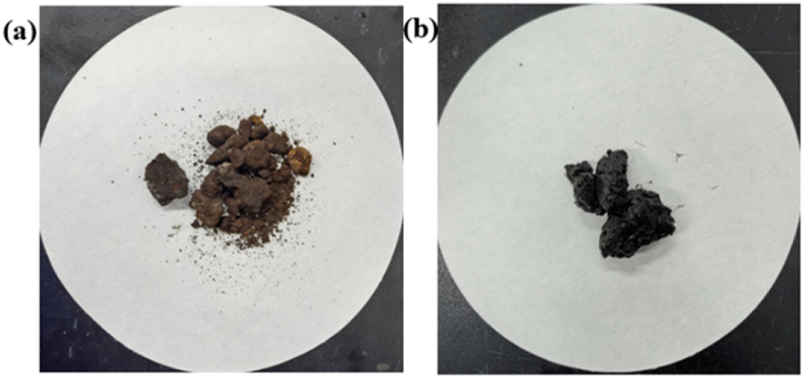
3.1.2. Blockage Morphology

The blockage samples appeared dark brown or black, with a viscous texture, existing in either a solid state or as a material with certain viscoelastic properties, exhibiting poor fluidity. SEM + EDS analysis revealed that, upon magnification, the blockage samples consisted of granular particles adhering and aggregating into clusters, with a significant amount of black organic matter present on the surface and surrounding areas, as shown in Figure 3. The blockage material primarily existed in a form where organic substances were encapsulated and adhered to inorganic particles. Elemental analysis further indicated that both workover-retrieved blockage samples and chip catcher-captured blockage samples contained Si, Cl, S, Ca, Cr, Fe, and Ba. Among these, Fe exhibited the highest mass concentration, accounting for 54.7% and 51.0% in the two respective samples.

3.1.3. High-Temperature Combustion Experiment Analysis

High-temperature combustion led to the separation of organic and inorganic components. During the combustion process, some bright-brown cemented residues adhered to the crucible, making them difficult to scrape off, and emitted a pungent burnt odor. The mass loss rate of the samples between 105 and 500 °C ranged from 15.31% to 21.53%, which is attributed to the volatilization and dissipation of the organic components, while the remaining inorganic residue accounted for 78.47% to 84.69%. When the organic content exceeds 10%, it not only reduces fluid mobility but also promotes aggregation, deposition, and adhesion between organic and inorganic materials. A high organic content is positively correlated with the location and severity of the blockage [31,32], which, to some extent, explains the observed organic–encapsulated-inorganic structure of the blockage material.

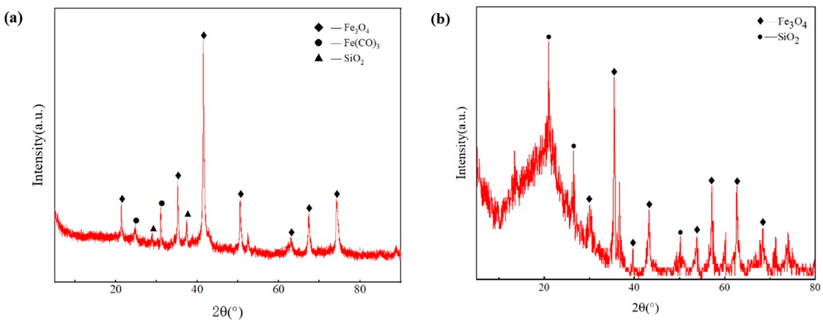
3.1.4. Inorganic Component Analysis of Blockage

X-ray diffraction (XRD) analysis revealed that the inorganic components of the workover-retrieved blockage samples were primarily composed of quartz (SiO2), magnetite (Fe3O4), and siderite (FeCO3), as shown in Figure 4a. while the chip catcher blockage samples mainly contained quartz (SiO2) and magnetite (Fe3O4), as shown in Figure 4b.
The potential sources of SiO2 can be classified into two main categories. X-ray diffraction (XRD) analysis revealed that the inorganic components of the workover-retrieved blockage samples were primarily composed of quartz (SiO2), magnetite (Fe3O4), and siderite (FeCO3), while the chip catcher blockage samples mainly contained quartz (SiO2) and magnetite (Fe3O4). The potential sources of SiO2 include quartz minerals in shale formations and proppant backflow during gas well production. According to a clay mineral composition analysis, the Weiyuan shale primarily consists of quartz, calcite, and clay minerals, while quartz sand proppant used in hydraulic fracturing may flow back into the wellbore from the formation [33].
The potential sources of Fe3O4 and FeCO3 can be attributed to three factors: formation rock minerals, wellbore casing corrosion, and iron ion accumulation in formation flowback fluids. Formation minerals such as pyrite and chlorite contribute to iron compounds in the blockage. Meanwhile, the CO2-rich environment in Weiyuan shale gas leads to long-term casing corrosion, forming FeCO3, Fe2O3, and Fe3O4 on the casing walls. Additionally, the high chloride concentration in the formation water accelerates corrosion by forming micro-galvanic cells, which induce pitting corrosion and further material degradation [34,35]. Furthermore, iron ions in formation flowback fluids may precipitate and flocculate over multiple recycling cycles, leading to the progressive accumulation of blockage materials.

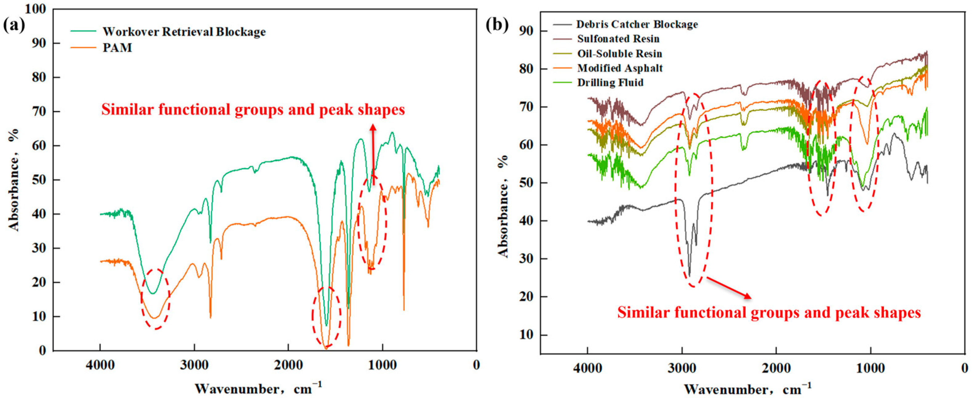
3.1.5. Organic Component Analysis of Blockage

Fourier-transform infrared (FT-IR) spectroscopy analysis of the blockage samples from the Weiyuan block revealed distinct absorption features, as shown in Figure 5a. The workover-retrieved blockage sample exhibited a broad and strong absorption peak in the 3000–3800 cm−1 range, primarily attributed to the stretching vibration of hydroxyl (–OH) groups. The absorption peak at 1600 cm−1 corresponds to the C=C stretching vibration in aromatic rings, while the peak at 1114 cm⁻1 is associated with the C–O stretching vibration in alcohols or esters. In contrast, the chip catcher blockage sample, as shown in Figure 5b, displayed a characteristic –CH2 peak at 2924 cm⁻1, suggesting the presence of heavy hydrocarbon components. Similarly, this blockage sample also exhibited a C=C stretching peak around 1600 cm−1, indicating the presence of conjugated π systems. Such functional groups enhance particle aggregation via π–π intermolecular interactions and increase the blockage viscosity by forming hydrogen bonds or electrostatic interactions with polar functional groups such as hydroxyl (–OH). Further spectral features include a C–F stretching vibration at 1261 cm−1, characteristic of aromatic fluorinated compounds, and a Si–O–Si symmetric stretching vibration at 800 cm⁻1, indicative of silicon-based polymers, which likely originate from silicone resins or wellbore coatings. The C–S stretching vibration at 622 cm−1 corresponds to sulfonate esters, potentially derived from sulfonated resins in drilling fluids, while the SO3 symmetric bending vibration at 564 cm−1 suggests the presence of persulfates. These functional groups reflect the complex organic composition of the blockage material, showing spectral similarities with modified bitumen, sulfonated resins, oil-soluble resins, and drag reducers. Based on these findings, the organic components in the blockage are likely related to polymeric materials from drilling fluids and fracturing fluids.

3.2. Construction of Blockage Depolymerization System

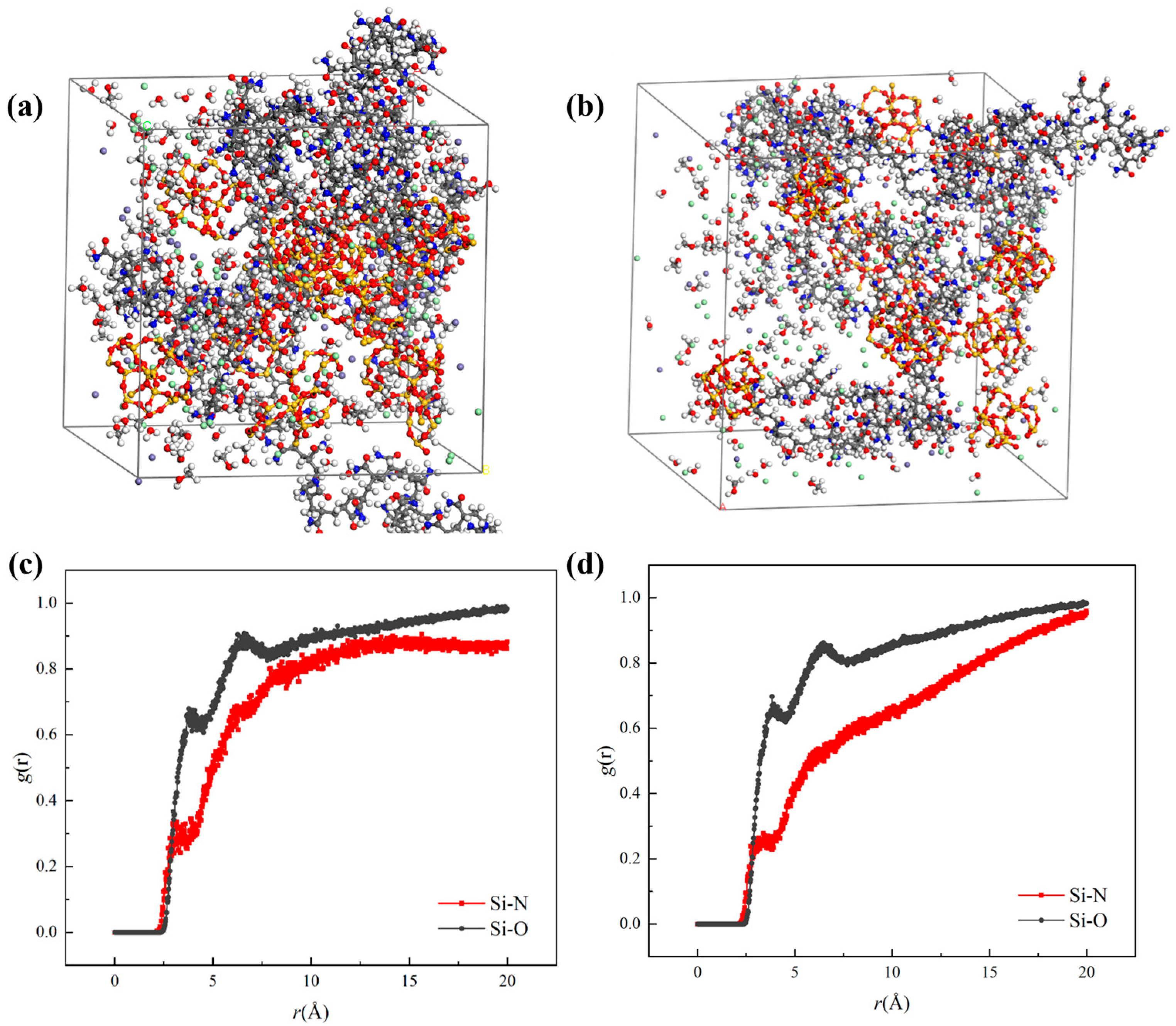
3.2.1. Analysis of Blockage Depolymerization and Dispersion Mechanism

Based on the analysis of the field blockage samples, it was found that the blockages primarily consist of an organic-phase-coated inorganic-phase aggregation structure. When dealing with such composite blockages, single-component agents are unable to penetrate effectively, resulting in limited removal efficiency. Furthermore, partially dissolved blockages tend to migrate deeper into the reservoir, leading to recurring blockages [36,37,38]. Previous analysis confirmed that a layer of organic matter was adhered to the blockage surface, containing a significant amount of iron. Infrared analysis also indicated that the organic components were associated with working fluids, such as fracturing and drilling fluids. A molecular aggregation model of the blockage, simulated based on its physicochemical properties, is shown in Figure 6a. The blockage mainly consists of SiO2 spherical cluster particles, an Fe3⁺ aqueous solution, and polyacrylamide monomers, a key component in fracturing fluids.
In the organic dispersion phase, molecular simulation revealed that adding alcohol-based substances significantly promotes the dispersion of aggregated blockage materials, as shown in Figure 6b. Alcohol molecules effectively separate organic molecules from the blockage into the unblocking fluid, reducing their adhesion and breaking the intermolecular aggregation forces of the organic phase, thereby lowering the adhesion and aggregation tendency of the blockage. The hydroxyl (-OH) groups in alcohols repel fluorinated aliphatic groups (C-F stretching) in polymers, and when combined with low-valence, neutral, or carboxyl-containing organic compounds as catalysts, they effectively weaken the adsorption interactions within the aggregated blockage structure, leading to its dispersion and depolymerization. In the radial distribution function (RDF) analysis, Si represents the Si atoms in SiO2, O represents the O atoms in water, and N represents the N atoms in polyacrylamide. This analysis indicates whether SiO2 particles tend to precipitate in water (dispersed state) or remain aggregated around polyacrylamide chains. As shown in Figure 6c, the black curve (with alcohol) is higher than the red curve (without alcohol), demonstrating that inorganic particles become more dispersed in the alcohol–water mixture, significantly enhancing dispersion and depolymerization. Building upon the dispersion phase, the addition of acidic substances further increases the difference in g(r) between the curves, as illustrated in Figure 6d. This indicates an enhanced decomposition of inorganic materials, while the polymer’s ability to adsorb solid particles is significantly reduced. Based on these findings, an “organic dispersion, inorganic decomposition” unblocking strategy was proposed, enabling targeted and efficient blockage removal.

3.2.2. Construction of Unblocking Fluid System

Based on the physicochemical properties of the blockage materials, it was found that the organic content and composition varied among different blockage samples. To address various well blockage conditions, three environmentally friendly unblocking fluid systems were developed by integrating the molecular simulation results. The details are as follows:
Neutral unblocking agent: Based on molecular simulation results and considering the organic-rich surface of the blockage, alcohol-based dispersants were selected to disrupt intermolecular forces within the organic components, enhancing depolymerization and exposing inorganic particles. The final formulation consists of 30% primary alcohol + 10% auxiliary alcohol + 1% hydrocarbons + 1% surfactant, which effectively breaks down and disperses the adhered organic residues, mineral precipitates, and solid particles, thereby mitigating polymeric blockage structures.
Acidic unblocking agent: The inorganic component of the blockage primarily consists of iron oxides with minor sand content. To effectively dissolve various types of inorganic scales, hydrochloric acid (HCl) was chosen as the primary acid due to its rapid dissolution of inorganic deposits and metal oxides, while acetic acid was used as a secondary acid to reduce HCl corrosion and introduce a moderate retardation effect, significantly enhancing the acid solution’s stability and longevity. Through acid concentration optimization, the final formulation was determined as 12% HCl + 6% acetic acid + 1% corrosion inhibitor + 1% iron ion stabilizer. As shown in Figure 7, the system effectively dissolves iron oxides, rock particles, and other inorganic scale deposits, and maintains them in solution, thereby significantly reducing the risk of blockage caused by inorganic precipitation.
Composite unblocking agent: A mixture of acidic and neutral unblocking agents is designed for severe blockages or when the blockage type is unknown in the field. This formulation leverages the synergistic effect of inorganic decomposition and organic dispersion, enabling a targeted dissolution and dispersion of wellbore blockages, ultimately achieving deep unblocking. To further verify the practical applicability of the proposed system, the composite unblocking fluid was compared with the conventional acid-based chemical unblocking fluid currently used in the Weiyuan block through a series of performance evaluation tests.

3.3. Performance Evaluation of the Unblocking Fluid System

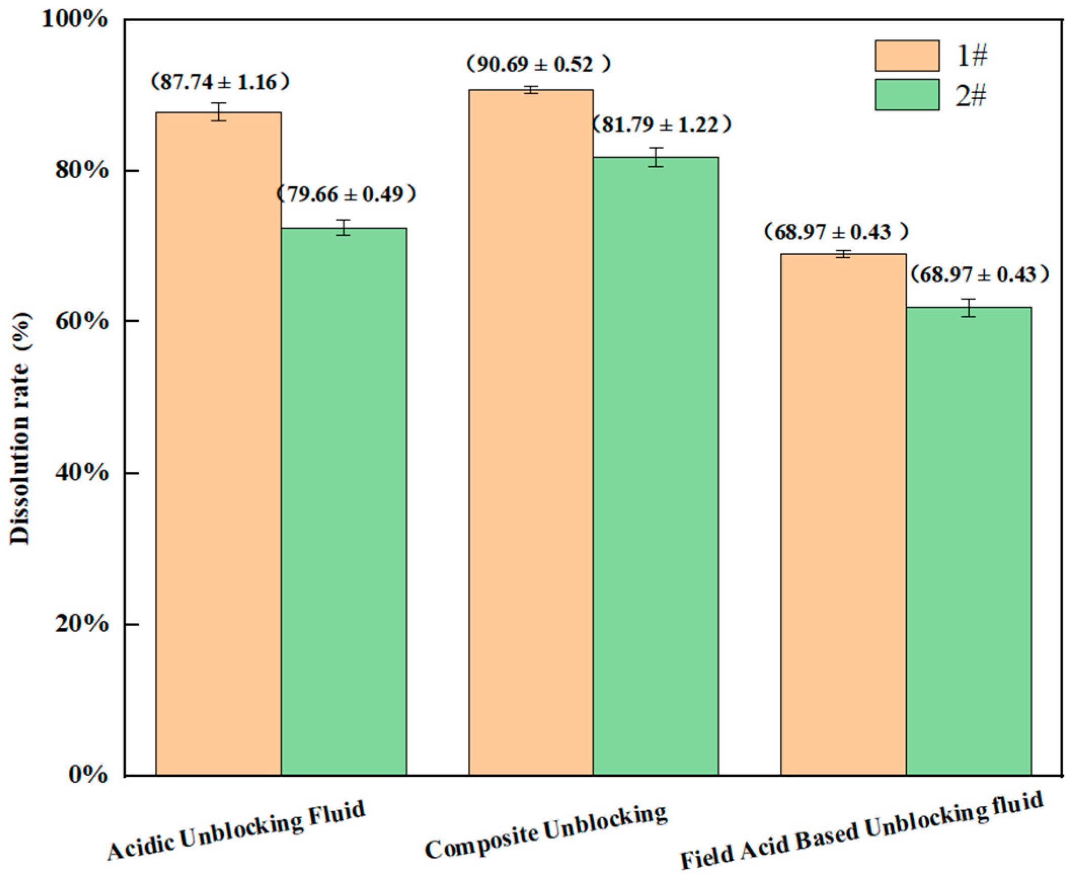
3.3.1. Compatibility and Static Dissolution Rate Measurement

The composite unblocking fluid system was formulated by blending neutral and acidic unblocking agents in a defined ratio. When mixed with formation water and left to stand for 4 h at both ambient and reservoir temperatures, the resulting solution remained clear, indicating good compatibility and stability of the system. A compositional analysis of the blockage samples retrieved from wellbore fishing operations and cutting traps revealed that both types were predominantly inorganic with a minor organic fraction, exhibiting typical multiphase composite blockage characteristics.
To evaluate the unblocking performance of the composite system, dissolution experiments were conducted separately on both types of blockages under identical conditions, with each test repeated in triplicate. The average dissolution rates and standard deviations were recorded. As shown in Figure 8, the composite fluid achieved average dissolution rates of 90.24% (±0.37%) for fishing-retrieved blockage and 82.13% (±0.41%) for cutting trap blockage, demonstrating excellent solubilization and dispersion capabilities sufficient to meet field unblocking requirements.
In contrast, conventional acid-based unblocking fluids exhibited significantly lower dissolution rates of only 69.28% (±0.46%) and 62.74% (±0.52%), respectively. To statistically verify the performance differences, a one-way analysis of variance (ANOVA) was applied to the dissolution data of the composite fluid, acidic unblocking fluid, and conventional acid system. The results revealed extremely significant differences in both blockage types—F = 1544.52, p < 0.0001 for fishing blockages and F = 411.75, p < 0.0001 for trap blockages—thereby confirming the superior unblocking efficiency of the composite system.

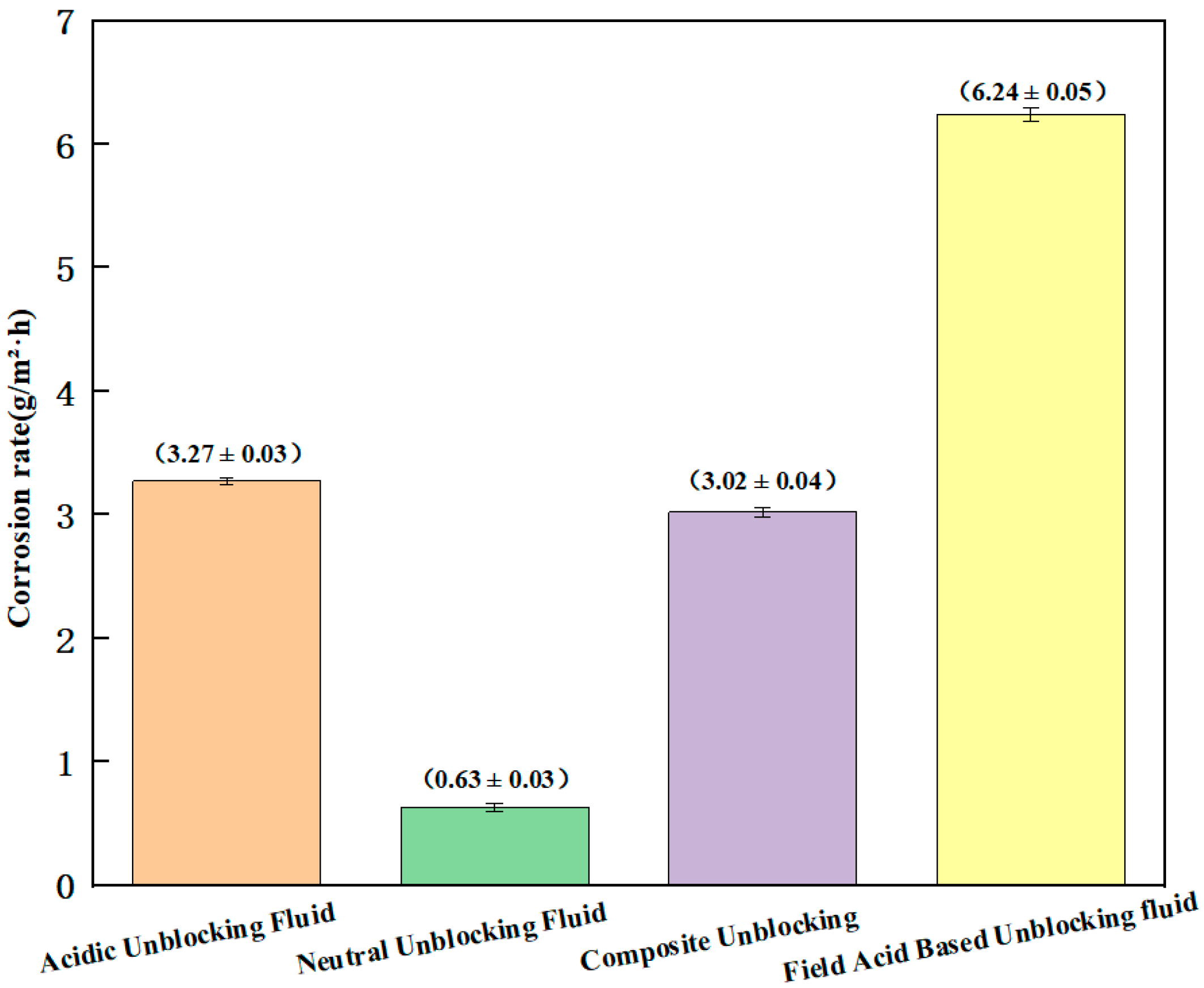
3.3.2. Corrosion Evaluation

Under static conditions at 90 °C, a corrosion performance comparison was conducted between three unblocking fluid systems developed in this study (acidic, neutral, and composite) and a conventional field-used acid-based unblocking fluid, with the aim of evaluating their impact on N80 steel. As shown in Figure 9, the average corrosion rates of the acidic, neutral, and composite systems were 3.27 g/m2·h, 0.63 g/m2·h, and 3.02 g/m2·h, respectively, all meeting or exceeding the Class I industry standard (≤6.5 g/m2·h), and indicating a relatively low corrosion risk to tubular materials. In contrast, the field-used acid-based fluid exhibited a corrosion rate as high as 6.24 g/m2·h, approaching the threshold limit of the industry standard and posing a significant corrosion risk. To statistically evaluate the performance differences, a one-way analysis of variance (ANOVA) was performed on the corrosion data. The results showed extremely significant differences among the fluid systems (F = 11034.22, p < 0.0001). The composite unblocking fluid demonstrated superior compatibility with metal materials while maintaining effective unblocking performance, making it more suitable for shale gas wells with high wellbore integrity requirements.

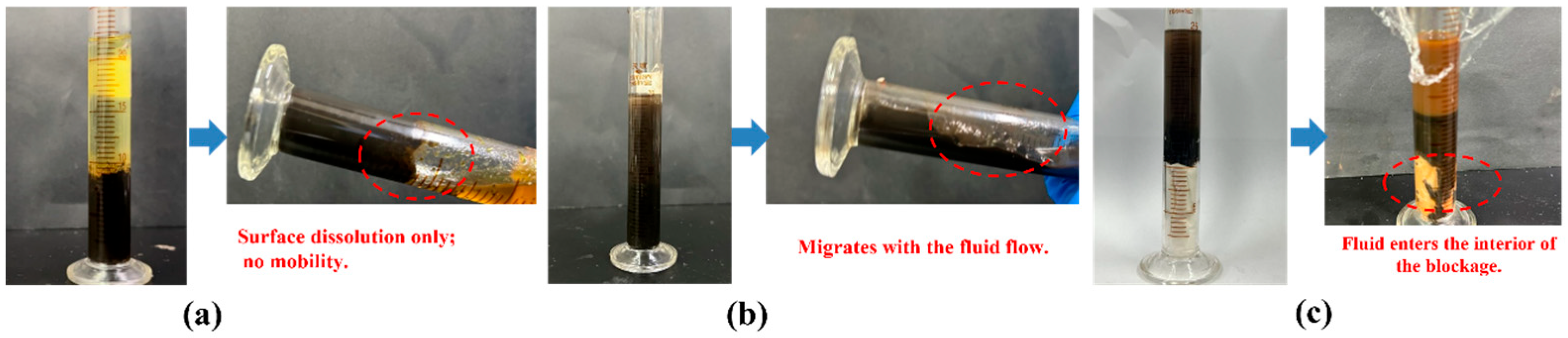
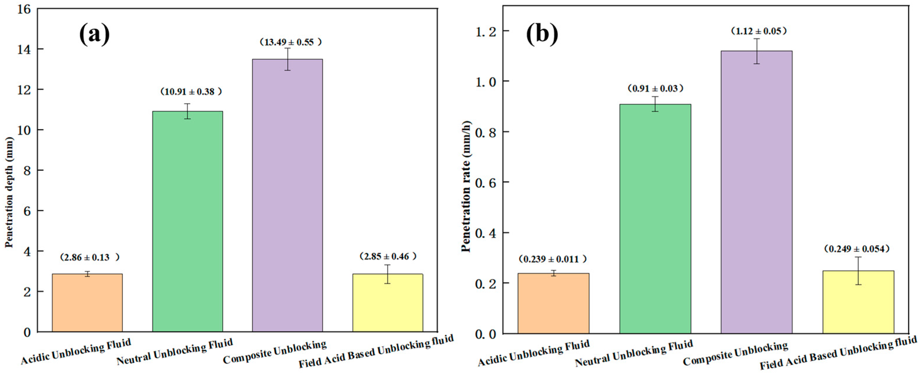
3.3.3. Evaluation of Unblocking Effect Under Simulated Wellbore Conditions

In actual wellbore environments, blockage materials typically form dense, multiphase composite structures that hinder the effective penetration of unblocking fluids into deeper regions. As a result, the action of the unblocking agents is often confined to the surface, leading to significantly reduced overall unblocking efficiency. To simulate complex blockage conditions in the wellbore and quantitatively evaluate the penetration capacity and unblocking performance of different fluid systems, this study constructed a cylindrical solid blockage model with defined thickness and porosity in a test tube. Penetration experiments were carried out under conditions with a limited contact area between the unblocking fluid and the blockage surface. The experimental results revealed that acidic unblocking agents exhibited excellent solubilization performance for loosely aggregated blockage materials. However, when applied to compacted blockage layers, their action was restricted to surface dissolution and could not effectively penetrate the internal structure, as shown in Figure 10a. This indicates that such agents are more suitable for inorganic blockages caused by scaling or corrosion products.
In contrast, although neutral unblocking agents exhibited a relatively lower overall dissolution rate, they demonstrated good performance in penetrating dense blockage structures. With a dispersion efficiency exceeding 90%, the neutral system effectively weakened the interparticle binding forces, detached organic components adsorbed on inorganic particle surfaces, and restored a certain degree of mobility to agglomerated blockages, thereby forming penetration channels, as illustrated in Figure 10b. This type of fluid is thus more suitable for tackling organic composite blockages associated with paraffin, asphaltenes, or polymer residues.
In wellbores characterized by complex blockage structures or severe degrees of clogging, relying solely on a single type of unblocking agent often fails to achieve satisfactory remediation. The experimental results demonstrated that the application of a neutral unblocking agent can effectively weaken the internal structure of the blockage, reduce interparticle adhesion, and lower the overall structural rigidity. This structural loosening facilitates the subsequent penetration and dissolution of inorganic components by an acidic unblocking agent. This synergistic mechanism, based on a “neutral pre-dispersion followed by acid dissolution” strategy, enables a one-step dual-action unblocking process. It significantly enhances the overall unblocking efficiency and fulfills the dual objectives of organic dispersion and inorganic decomposition.
To verify the effectiveness of the proposed synergistic unblocking mechanism, the penetration performance of different unblocking fluid systems was further evaluated. As shown in Figure 11, the composite unblocking fluid exhibited an average penetration depth of 13.49 ± 0.55 mm, representing a 23.6% increase compared to the neutral system (10.91 ± 0.38 mm), and was significantly greater than that of the standalone acidic unblocking fluid (2.86 ± 0.13 mm) and the field-used acid-based fluid (2.85 ± 0.46 mm). In terms of penetration rate, the composite system also demonstrated a clear advantage, achieving an average rate of 1.12 ± 0.05 mm/h, which was 23% higher than that of the neutral system (0.91 ± 0.03 mm/h), and was substantially superior to the field acid-based system (0.249 ± 0.054 mm/h). As shown in Figure 10c, the composite unblocking fluid system is capable of significantly disrupting the internal structure of the blockage material, thereby achieving effective deep unblocking. Moreover, the observed improvements in penetration performance and dissolution efficiency are in good agreement with the molecular simulation results. An RDF analysis demonstrated that the introduction of an acid and an organic dispersant led to a notable decrease in the peak intensity and a marked broadening of the distribution between the organic and inorganic components, indicating a looser structure and reduced aggregation within the blockage. This structural relaxation facilitates deeper fluid penetration and more efficient disaggregation, and the microscopic evolution trends are highly consistent with the experimental observations. Furthermore, a one-way analysis of variance (ANOVA) performed on the penetration performance of different unblocking fluid systems revealed statistically significant differences in both penetration depth (F = 541.18, p < 0.0001) and penetration rate (F = 406.66, p < 0.0001), further confirming the superior penetration capability and unblocking effectiveness of the composite fluid system under complex blockage conditions.
To systematically evaluate the applicability of different unblocking fluid systems under actual wellbore conditions, key performance indicators, including dissolution efficiency, corrosion behavior, and penetration capability, must be comprehensively considered. The results of the three laboratory-designed unblocking fluids and a field-used acid-based system were summarized and compared, as shown in Table 3. The composite unblocking fluid exhibited superior performance across all metrics, achieving the highest average dissolution rate of 90.69%, representing an improvement of over 31% compared to the field acid-based system. In terms of penetration ability, the composite system reached a penetration depth of 13.49 mm, approximately 4.7 times greater than that of the field system, along with a markedly enhanced penetration rate. Moreover, the composite system maintained a corrosion rate of 3.02 g/m2·h, which is about 52% lower than that of the field-used fluid, thereby significantly improving safety for downhole tubular materials while ensuring effective unblocking.
The composite system, based on the rational combination of neutral and acidic agents, leverages the respective advantages of both components: efficient dispersion of organic materials and deep dissolution of inorganic scales. This synergistic “organic dispersion–inorganic dissolution” mechanism not only enhances the overall treatment efficiency for complex blockages but also reduces the risk of secondary blockage caused by residual or migrated materials. Additionally, the formulation offers high tunability, allowing the ratio of neutral-to-acidic components to be adjusted according to the organic-to-inorganic composition of the blockage. This enables more targeted and effective unblocking strategies and enhances the adaptability and engineering applicability of the fluid system.

3.4. Wellbore Unblocking Process Integration

3.4.1. Unblocking Process

To enhance the targeting of unblocking measures, improve operational efficiency, and reduce production costs, the following well selection principles were established. First, wells with stable production before shutdown, sufficient recoverable reserves, and high potential for production recovery were selected. Second, it was ensured that the tubing and casing were connected, allowing prior unblocking measures to facilitate effective fluid intake into the formation or wellbore. Considering factors such as unblocking effectiveness, operation time, and cost, a non-tubing-movement approach was adopted, wherein a high-pressure pump truck was used to inject the unblocking fluid into the tubing to clear the wellbore. The distribution of blockages was assessed by monitoring wellhead weight variations, while coiled tubing sand washing was utilized to retrieve blockage samples, enabling the analysis of blockage composition, location, type, and severity to select the appropriate unblocking fluid system. Based on different blockage conditions, tailored well-cleaning methods were applied. If the coiled tubing encountered resistance mid-run, a circulating well-cleaning method was used, in which the fluid was circulated until the outlet ran clear, followed by the injection of 2 m3 of unblocking agent, with a reaction time of 0.5–1 h to ensure full interaction and dissolution of the blockage. If the coiled tubing successfully reached the target depth in one pass, a dragging well-cleaning method was employed. In this approach, after circulating until the outlet was clear, 2 m3 of unblocking agent were injected through the tubing, followed by an upward dragging motion of the tubing to facilitate the injection of 10 m3 of unblocking agent into the vertical section. To prevent corrosion of the wellbore and equipment, an appropriate amount of clean water was injected to displace the unblocking fluid into the formation or recover it, ensuring the completion of the wellbore cleaning process.

3.4.2. Field Implementation Effect

Field unblocking operations were carried out in two wells, Weiyuan 28-4 and 28-7. The blockage materials retrieved from both wells exhibited a viscous texture and complex composition and were found to be insoluble in water and alkaline cleaners. Based on the observed blockage characteristics, a neutral unblocking fluid was selected for treatment, consisting of 30 m3 of concentrate and 60 m3 of diluent, totaling 90 m3 of fluid per well. Since the wells were brought into production in 2023, repeated wellbore blockage events with high fluctuation amplitudes have led to significant production declines. Following unblocking in Well 28-7, as shown in Figure 12a, the average daily gas production over the 30 days prior to treatment was 1.7 × 10⁴ m3/d. Post-treatment, the peak daily production reached 6.68 × 10⁴ m3/d, with a 30-day average of 4.9 × 10⁴ m3/d, resulting in an average production increase of 3.2 × 10⁴ m3/d. Notably, gas production remained stable at approximately 3 × 10⁴ m3/d for nearly a year following the treatment, indicating a sustained and significant unblocking effect. In Well 28-4, no secondary blockage was observed for an extended period after treatment, and production remained stable. As shown in Figure 12b, the gas output has since been maintained at approximately 2.2 × 10⁴ m3/d, further demonstrating the effectiveness of the unblocking operation.

4. Conclusions

(1)
The blockage material in the Weiyuan block primarily exists as an inorganic-dominated aggregate with organic components as a secondary phase, with an inorganic-to-organic ratio of approximately 8:2. The main inorganic components are Fe3O4 and SiO2, while the organic components are mainly associated with polymeric materials from drilling fluids and fracturing fluids;
(2)
Gas wellbore blockage in gas wells is typically induced by the combined effects of multiple factors, with the blockage material often exhibiting a complex multiphase composite structure. To elucidate the mechanism of dispersion and disintegration, this study integrated molecular simulation with laboratory experiments based on the physicochemical properties of the blockage. A synergistic unblocking strategy of “organic dispersion + inorganic dissolution” was proposed from a microscopic perspective. According to the varying proportions of organic and inorganic components in the blockage, three types of unblocking fluid systems—neutral, acidic, and composite—were developed to suit different blockage scenarios. The results demonstrated that, when dealing with dense composite blockages, the composite fluid system exhibited superior penetration and unblocking efficiency in simulated wellbore models, highlighting its strong potential for application in complex downhole environments;
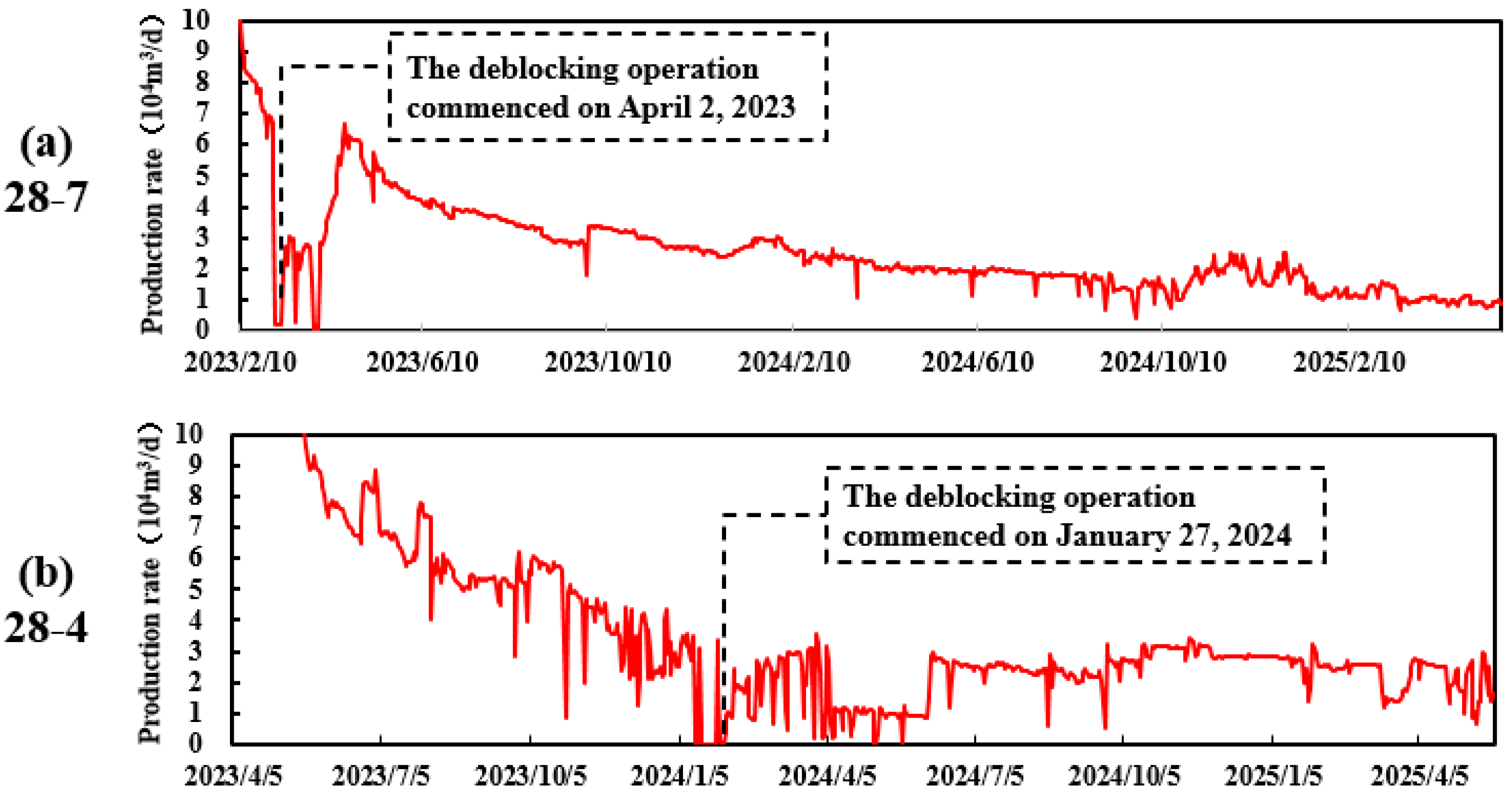
(3)
Blockages in shale gas wells typically exhibit pronounced multiphase complexity, posing considerable challenges for effective remediation. This underscores the need for high-efficiency, adaptable unblocking technologies tailored to the organic–inorganic composite nature of such obstructions. In response, this study developed a composite unblocking fluid system with tunable formulation flexibility, wherein the ratio of neutral-to-acidic components can be adjusted according to the specific organic/inorganic composition of the blockage. This design enables the system to accommodate a wide range of reservoir types and complex geological conditions. Field trials were conducted in two shale gas wells (Wei 28-4 and Wei 28-7) to evaluate the system’s performance under real-world conditions. The results demonstrated significant improvements in productivity: the Wei 28-7 well achieved an average post-treatment production increase of 3.2 × 10⁴ m3/d, while the Wei 28-4 well maintained a stable output of 2.2 × 10⁴ m3/d without recurrence of blockage. These outcomes validate the system’s capability to effectively remove complex wellbore blockages and extend well productivity. The technology has now entered the promotion and application phase, offering a robust and adaptable solution for efficient wellbore blockage mitigation in similar shale gas development scenarios;
(4)
Wellbore scaling and blockages are long-term issues that require repeated unblocking operations. Further research is needed to better understand the formation mechanisms of such complex blockages, allowing for the development of more targeted and long-lasting unblocking fluid systems.

Author Contributions

Conceptualization, Y.Y.; methodology, Y.W.; formal analysis, L.Z.; investigation, J.X.; data curation, Q.H.; writing—original draft preparation, T.Z.; writing—review and editing, B.Q.; visualization, J.Z. All authors have read and agreed to the published version of the manuscript.

Funding

This study is a result of university–enterprise collaborative research. All related expenses were funded by the collaborative project “Study on the Mechanism of Wellbore Blockage and Its Composite Unblocking Fluid System”, grant number CQZT-yyqxmb-2024-JS-151.

Data Availability Statement

The original contributions presented in this study are included in the article. Further inquiries can be directed to the corresponding author.

Conflicts of Interest

Authors Yadong Yang, Yixuan Wang, Longqing Zou, Jianfeng Xiao, Qiyue He and Teng Zhang were employed by CNPC Chuan-Qing Drilling Engineering Company Limited. The remaining authors declare that the research was conducted in the absence of any commercial or financial relationships that could be construed as a potential conflict of interest.

References

  1. Xie, J.; Zhao, S. Hydrocarbon accumulation and key exploration & development technologies of Changning-Weiyuan marine shale gas field, southern Sichuan. Pet. Res. 2021, 6, 1–15. [Google Scholar] [CrossRef]
  2. Tan, X. Composite technology of plug removal, cleanup and descaling for shale gas well and its application: A case study of Weiyuan and Rongxian operation areas, Sichuan Basin. Nat. Gas Explor. Dev. 2022, 45, 116–122. [Google Scholar] [CrossRef]
  3. Sheng, G.; Su, Y.; Wang, W. A new fractal approach for describing induced-fracture porosity/permeability/ compressibility in stimulated unconventional reservoirs. J. Pet. Sci. Eng. 2019, 179, 12. [Google Scholar] [CrossRef]
  4. Lv, M.; Guo, T.; Jia, X.; Wen, D.; Chen, M.; Wang, Y.; Qu, Z.; Ma, D. Study on the pump schedule impact in hydraulic fracturing of unconventional reservoirs on proppant transport law. Energy 2024, 286, 129569. [Google Scholar] [CrossRef]
  5. Lei, Q.; Yun, X.U.; Cai, B.; Guan, B.; Wang, X.; Bi, G.; Li, H.; Li, S.; Ding, B.; Fu, H.; et al. Progress and prospects of horizontal well fracturing technology for shale oil and gas reservoirs. Pet. Explor. Dev. 2022, 49, 166–172. [Google Scholar] [CrossRef]
  6. Xu, C.; Kang, Y.; You, Z.; Chen, M. Review on formation damage mechanisms and processes in shale gas reservoir: Known and to be known. J. Nat. Gas Sci. Eng. 2016, 36, 1208–1219. [Google Scholar] [CrossRef]
  7. Yan, X.; You, L.; Kang, Y.; Deng, S.; Xu, C. Formation Damage Induced by Oil-Based Drilling Fluid in a Longmaxi Shale Gas Reservoir: A Comprehensive View of the Drilling, Stimulation, and Production Processes. Energy Fuels 2023, 37, 945–954. [Google Scholar] [CrossRef]
  8. Sun, J.; XU, C.; Kang, Y.; Zhang, J. Research Progress and Development Recommendations Covering Damage Mechanisms and Protection Technologies for Tight/Shale Oil and Gas Reservoirs. Pet. Drill. Tech. 2020, 48, 1–10. [Google Scholar] [CrossRef]
  9. Zhang, J.; Zhu, D.; Hill, A.D. Water-Induced Fracture Conductivity Damage in Shale Formations. In Proceedings of the SPE Hydraulic Fracturing Technology Conference, The Woodlands, TX, USA, 3–5 February 2015. [Google Scholar] [CrossRef]
  10. Reinicke, A.; Rybacki, E.; Stanchits, S.; Huenges, E.; Dresen, G. Hydraulic fracturing stimulation techniques and formation damage mechanisms—Implications from laboratory testing of tight sandstone–proppant systems. Chem. Erde—Geochem.—Interdiscip. J. Chem. Probl. Geosci. Geoecology 2010, 70 (Suppl. S3), 107–117. [Google Scholar] [CrossRef]
  11. Huang, W.; Lei, M.; Qiu, Z.; Leong, Y.-K.; Zhong, H.; Zhang, S. Damage mechanism and protection measures of a coalbed methane reservoir in the Zhengzhuang block. J. Nat. Gas Sci. Eng. 2015, 26, 683–694. [Google Scholar] [CrossRef]
  12. Dai, C. Formation Damage During Chemical Flooding. In Formation Damage During Improved Oil Recovery; Yuan, B., Wood, D.A., Eds.; Gulf Professional Publishing: Houston, TX, USA, 2018; pp. 275–304. [Google Scholar] [CrossRef]
  13. Bai, J.; Kang, Y.; Chen, Z.; You, L.; Chen, M.; Li, X. Changes in retained fracturing fluid properties and their effect on shale mechanical properties. J. Nat. Gas Sci. Eng. 2020, 75, 103163. [Google Scholar] [CrossRef]
  14. King, G.E.; Durham, D. Chemicals in drilling, stimulation, and production. Advances in chemical pollution, environmental management and protection. Adv. Chem. Pollut. Environ. Manag. Prot. 2017, 1, 47–61. [Google Scholar] [CrossRef]
  15. Sun, J.; Xu, C.; Kang, Y.; Jing, H.; Zhang, J.; Yang, B.; You, L.; Zhang, H.; Long, Y. Formation damage mechanism and control strategy of the compound function of drilling fluid and fracturing fluid in shale reservoirs. Pet. Explor. Dev. 2024, 51, 430–439. [Google Scholar] [CrossRef]
  16. Guo, J.; Li, Y.; Wang, S. Adsorption damage and control measures of slick-water fracturing fluid in shale reservoirs. Pet. Explor. Dev. 2018, 45, 336–342. [Google Scholar] [CrossRef]
  17. Ekanem, E.M.; Rücker, M.; Yesufu-Rufai, S.; Spurin, C.; Ooi, N.; Georgiadis, A.; Berg, S.; Luckham, P.F. Novel adsorption mechanisms identified for polymer retention in carbonate rocks. JCIS Open 2021, 4, 100026. [Google Scholar] [CrossRef]
  18. Liu, S.Q.; Zhang, J.C.; Xu, J.C. Investigation on Polymer Adsorption and Retention in a Polymer Flooded Reservoir. Adv. Mater. Res. 2013, 734–737, 1200–1203. [Google Scholar] [CrossRef]
  19. Al-Hajri, S.; Mahmood, S.M.; Akbari, S.; Abdulelah, H.; Yekeen, N.; Saraih, N. Experimental investigation and development of correlation for static and dynamic polymer adsorption in porous media. J. Pet. Sci. Eng. 2020, 189, 106864. [Google Scholar] [CrossRef]
  20. Shi, B.; Wang, Z.; Zhang, Z.; Xu, Y.; Ling, K. A State of the Art Review on the Wellbore Blockage of Condensate Gas Wells: Towards Understanding the Blockage Type, Mechanism, and Treatment. Lithosphere 2022, 2022, 8076631. [Google Scholar] [CrossRef]
  21. Kamal, M.S.; Hussein, I.; Mahmoud, M.; Sultan, A.S.; Saad, M.A. Oilfield scale formation and chemical removal: A review. J. Pet. Sci. Eng. 2018, 171, 127–139. [Google Scholar] [CrossRef]
  22. Feng, B.; Ke, Z.; Liu, Y.; Shangguan, S.; Li, X.; Cui, Z. Plugging mechanism and plugging removal technologies for enhanced geothermal system reservoirs. Nat. Gas Ind. 2022, 42, 165. [Google Scholar] [CrossRef]
  23. Yuan, Y.; Du, J.; Liu, P.; Zou, Q.; Chen, X.; Liu, J. Research on Wellbore Blockage Mechanism and Blockage Removal Technology of Shale Gas Wells. J. Phys. Conf. Ser. 2024, 2834, 012167. [Google Scholar] [CrossRef]
  24. Lv, Y.; Ou, J.; Fu, H.; Li, J.; Luo, Z.; Yang, X.; Zhao, J.; Yang, T. Unblocking Process of Complex Sulfur–Iron Scale Blockage in Sulfur-Bearing Gas Wells and Its Mechanism. Nat. Gas Ind. 2022, 42, 165–183. [Google Scholar] [CrossRef] [PubMed]
  25. Yang, X.; Sheng, L.; Shi, J.; Fei, H.; Guo, D.; Bai, H.; Yao, E. Mechanism of Salt Precipitation Blockage in Low-Producing Gas Wells and the Method of Acidification Blockage Removal. ACS Omega 2024, 9, 10886–10896. [Google Scholar] [CrossRef]
  26. Mahmoudi, M.; Roostaei, M.; Fattahpour, V.; Uzcatequi, A.; Cyre, J.; Sutton, C.; Fermaniuk, B. Standalone sand control failure: The role of wellbore and near wellbore hydro-thermo-chemical phenomenon on the plugging and the flow performance impairments of the standalone sand screen. In Proceedings of the SPE Thermal Well Integrity and Design Symposium, Banff, AB, Canada, 27–29 November 2018. [Google Scholar] [CrossRef]
  27. Mubarak, G.; Verma, C.; Barsoum, I.; Alfantazi, A.; Rhee, K.Y. Internal corrosion in oil and gas wells during casings and tubing: Challenges and opportunities of corrosion inhibitors. J. Taiwan Inst. Chem. Eng. 2023, 150, 105027. [Google Scholar] [CrossRef]
  28. Nikoo, A.H.; Ghaedi, M.; Malayeri, M.R.; Riazi, M. Analysis of wellbore clogging by asphaltene deposition using interaction energies. Fuel 2023, 352, 129111. [Google Scholar] [CrossRef]
  29. SY/T 5405-2019; Performance Test Methods and Evaluation Indicators for Corrosion Inhibitors for Acidizing. China’s Ministry of Petroleum and Chemical Industry: Beijing, China, 2019.
  30. SY/T 0600-2009; Prediction Methods for Scaling Tendency in Oil-Field Water. China’s Ministry of Petroleum and Chemical Industry: Beijing, China, 2009.
  31. Davudov, D.; Moghanloo, R.G.; Akita, E.; Karami, H. A diagnostic approach to predict asphaltene deposition in reservoir and wellbore. In Proceedings of the SPE Western Regional Meeting, Garden Grove, CA, USA, 22–26 April 2018. [Google Scholar] [CrossRef]
  32. Xu, H.; Wang, S.; Cheng, C.; Li, Q.; Liu, Y.; Qi, J.; Wu, J. Organic Solid Blocking Mechanism and Unblocking Technology for Ultra-Deep and High Pressure Oil Wells from Tarim Basin. In Proceedings of the International Petroleum Technology Conference, Bangkok, Thailand, 1–3 March 2023. [Google Scholar] [CrossRef]
  33. Zhang, H.; Yang, S.; Liu, D.; Li, Y.; Luo, W.; Li, J. Wellbore cleaning technologies for shale-gas horizontal wells: Difficulties and countermeasures. Nat. Gas Ind. B 2020, 7, 190–195. [Google Scholar] [CrossRef]
  34. Hoa, L.Q.; Bäßler, R.; Bettge, D.; Buggisch, E.; Schiller, B.N.; Beck, M. Corrosion Study on Wellbore Materials for the CO₂ Injection Process. Processes 2021, 9, 115. [Google Scholar] [CrossRef]
  35. Zhao, L.; Zhang, Y.; He, Y.; Yang, Z.; Liang, X.; Wang, X.; Mao, Q. Study on the Mechanism of Wellbore Blockage and Scaling Trend Prediction of Keshen Block. Processes 2024, 12, 782. [Google Scholar] [CrossRef]
  36. Xiao, L.; Hou, J.; Li, J. Performance evaluation and application of organic plug removal agent and non-acid plug removal system. Oilfield Chem. 2020, 37, 658–664. [Google Scholar]
  37. Yang, J.; Feng, Y.; Zhang, B.; Tang, Y.; Jiang, Z. A blockage removal technology for natural gas hydrates in the wellbore of an ultra-high pressure sour gas well. Nat. Gas Ind. B 2021, 8, 188–194. [Google Scholar] [CrossRef]
  38. Li, S.; Du, J.; He, J.; Sun, D.; Qiao, L.; Wang, S. Research progress of natural gas well wellbore declogging working fluid. Appl. Chem. Ind. 2024, 53, 238. [Google Scholar] [CrossRef]
Figure 1. Original images of blockage samples: (a) 1#—blockage retrieved from workover fishing operations; (b) 2#—blockage captured by the chip catcher.
Processes 13 01684 g001
Figure 2. Workflow of the molecular simulation method.
Processes 13 01684 g002
Figure 3. (a) SEM of workover retrieval blockage; (b) SEM of debris-catcher blockage.
Processes 13 01684 g003
Figure 4. (a) XRD spectrum of workover retrieval blockage; (b) XRD spectrum of debris-catcher blockage.
Processes 13 01684 g004
Figure 5. (a) FT-IR spectra of workover retrieval blockage samples; (b) FT-IR spectra of debris-catcher blockage samples.
Processes 13 01684 g005
Figure 6. Molecular simulation of blockage depolymerization: (a) blockage state before depolymerization; (b) blockage state after depolymerization; (c) RDF before depolymerization; (d) RDF after depolymerization.
Processes 13 01684 g006
Figure 7. Dissolution effect of acidic unblocking agent on inorganic scale: (a) workover-retrieved blockage sample; (b) chip catcher-captured blockage sample.
Processes 13 01684 g007
Figure 8. Dissolution performance of different unblocking fluid systems on solid-phase blockage materials.
Processes 13 01684 g008
Figure 9. Corrosion rates of different unblocking fluid systems on N80 steel under static conditions at 90 °C.
Processes 13 01684 g009
Figure 10. Dispersion and dissolution effects of different unblocking fluid systems on blockages under wellbore conditions: (a) acidic unblocking agent; (b) neutral unblocking agent; (c) acidic unblocking agent.
Processes 13 01684 g010
Figure 11. Penetration performance of the composite unblocking fluid system in simulated wellbore blockage: (a) penetration depth; (b) penetration rate.
Processes 13 01684 g011
Figure 12. Production performance characteristics after unblocking.
Processes 13 01684 g012
Table 1. Blockage and unblocking conditions of selected wells.
No.WellAbnormal TypeUnblocking TypeUnblocking Result
1W202H22-8Suspected horizontal section blockageMinor Workover and FlushingDecline
2W204H48-4Tubing installation obstruction after pressure channelingMicrobubble Well CleaningNot Increased
3W204H48-5Tubing installation obstruction after pressure channelingMicrobubble Well CleaningNot Increased
4W202H16-8Wellbore contamination, tubing blockageNitrogen Foam Well CleaningNot Increased
5W204H51-5Sand blockage in tubingNitrogen Foam Well CleaningNot Increased
6W204H33-1Flow restriction in the annulusSurfactant Well CleaningNot Increased
7W204H10-2Wellbore contamination, tubing blockageSurfactant Well CleaningNot Increased
Table 2. Formation water analysis results (mg/L).
WellpHFe3+/Fe2+Na+Mg2+K+Ba2+ClCO32−SO42−NO3−Total Salinity
W204H477.398.2611,789.6496.63150.51190.4319,590.129.391.1996.8231,924.73
W204H497.23141.816417.5131.14311.19539.1110,769.28318.282560.2855.1421,001.93
W204H417.1948.844812.5735.4460.1110.156031.2828.15329.9528.5811,336.23
W204H517.7973.514669.9727.2542.477.646793.5121.37230.1221.3411,813.67
Table 3. Comparative summary of performance metrics for different unblocking fluid systems.
Unblocking Fluid
System
Dissolution Rate
of Blockage Sample #1 (%)
Dissolution Rate
of Blockage Sample #2 (%)
Corrosion Rate (g/m2·h)Penetration Depth (mm)Penetration Rate (mm/h)
Acidic Unblocking Fluid87.74 (±1.16)79.66 (±0.49)3.27 (±0.03)2.86 (±0.13)0.239 (±0.011)
Neutral Unblocking Fluid//0.63 (±0.03)10.91 (±0.38)0.9 (±0.03)
Composite Unblocking90.69 (±0.52)81.79 (±1.22)3.02 (±0.04)13.49 (±0.55)1.12 (±0.05)
Field Acid-Based Unblocking Fluid68.97 (±0.43)61.90 (±1.18)6.24 (±0.05)2.85 (±0.46)0.249 (±0.054)
Disclaimer/Publisher’s Note: The statements, opinions and data contained in all publications are solely those of the individual author(s) and contributor(s) and not of MDPI and/or the editor(s). MDPI and/or the editor(s) disclaim responsibility for any injury to people or property resulting from any ideas, methods, instructions or products referred to in the content.

