1. Introduction
The carbonate reservoir of the Maokou Formation in the middle region of the Sichuan Basin, China, is an important carrier for deep natural oil and gas enrichment [
1]. The reservoir space dominated by dolomite is complex and diverse. The characteristics of low porosity and low permeability of the strata make acid fracturing technology the key to increasing oil and gas production [
2,
3,
4,
5,
6,
7,
8]. The depth of the Maokou Formation is generally 4500–6000 m, which belongs to the medium-deep or deep strata. When the reservoir is modified, it faces the problems of high temperature, high fracturing pressure, and high extension pressure. There are differences in rock mineral components and geological structures between the formations of the Maokou Group; the direction and morphology of acid etching cracks are difficult to predict and control [
9,
10,
11], and the reservoir modification effect is significantly different under different acid systems. Optimizing acid fracturing parameters according to formation characteristics is the premise of improving oil and gas exploitation efficiency [
12,
13,
14,
15,
16].
Turning acid, crosslinking acid, solid acid, organic acid, self-generated acid, and gel acid are commonly used in field engineering at present [
17,
18,
19]. The effect of different acid fluids on reservoir modification is reflected in the efficiency of dissolution, fracture conductivity, and reservoir adaptability. The gelling agent in the gelatin acid can increase the viscosity of the solution, delay the reaction rate between the acid solution and the rock, improve the effective action distance of the acid solution [
20], and also has the advantages of low filtrate loss and strong carrying sand capacity. The self-generated acid front process has a high cost and is suitable for medium and deep strata. It can effectively reduce the strength of the rock, conducive to the communication of natural cracks. At the same time, the surface roughness of the main crack is reduced. The front process of slippery water is simple, and its own low frictional resistance can be quickly pumped into the formation, which is more suitable for the slow reaction rate of acid rock. “Self-acid pre-added gelatin acid” and “slippery water pre-added gelatin acid” are two commonly used acid systems in the field at present. However, the compatibility between the two systems and the Maokou Group cloud ash interbedded reservoir has not been verified.
In view of the above problems in acid fracturing reservoir modification of the Maokou group, this paper studies the cracking and expansion laws of acid fracturing by a real three-axis acid fracturing physical simulation experiment [
21,
22,
23]. The experimental samples were taken from the full diameter core at a depth of 4600–6000 m in the second section of Maokou Formation of Pengyang 1 well and Pengyang 5 Well in central Sichuan. The core was cast into a cube of 300 mm by the concrete wrapping method to meet the requirements of the experiment. A simulated wellbore with a diameter of 1.2 cm and a length of 12 cm was installed, and a hole of 2 cm was reserved below to simulate the bare section. According to the actual acid solution formula on site, three types of fracturing fluids, self-generated acid, gelatinous acid, and slippery water, were prepared in the laboratory. It was also achieved by pre-injection of self-generated acid or slippery water into the pipeline and naked eye sections. The in situ stress environment of the core is simulated by the three-axis pressurization system, and the actual displacement of the field engineering is simulated by the feeding pressurization system. Four sets of carbonate rock acid fracturing experiments with different depths and different acid systems were carried out. The results were verified by the transformation of the field process. The “self-acid + gelatinizing acid” system can significantly reduce the fracture pressure. The morphology of acid etching cracks is more complex. The cross section is more deeply etched. Acidic cracks are not easy to pass through the dense calcite vein, but it is easier to communicate the interface between the cloud rock and limestone to produce a turn. The injection of self-generated acid at the site helps to unblock and remove pollution. The injection of gelatinous acid to communicate the natural weak surface can effectively increase the length of the fracture and improve the oil and gas production effect.
2. Experimental Method
2.1. Mineral Component Analysis and Sample Preparation
The four samples required for the experiment are the full diameter cores from the Pengyang block in the middle of the Sichuan Basin, which are, respectively, from the second section 6033.85 m, 6007.89 m of PY1 well, the second section 4097.85 m and 4601.86 m of PY5 well. Firstly, the mineral composition of rocks was analyzed by X-ray. Small pieces of rock are hammered off each core and ground into powder grains less than 40 um in diameter. At the same time, it is necessary to ensure that the number of grains in the illuminated volume meets the requirements. Each mineral has a unique X-ray diffraction pattern. The relative content of each mineral component can be calculated by matching the position and peak intensity of the diffraction peak. The average dolomite content of PY5 well Maokou 2nd section at a depth of 4600 m is more than 50%. It also contains a small amount of quartz. The average calcite content of PY1 well Maokou 2nd section at a depth of 6000 m is more than 90%. It also contains a small amount of dolomite (
Table 1).
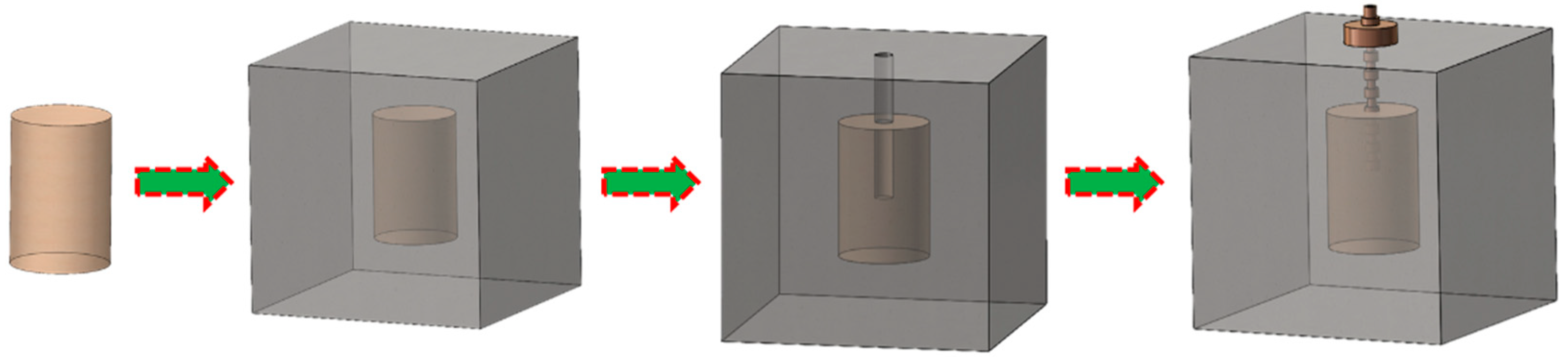
The full diameter carbonate core in the wellbore is cylindrical with a diameter of 10 cm and a length of 15~20 cm. The cylindrical specimens cannot be used directly in true triaxial acid press equipment. It needs to be poured into a concrete cube of 300 mm × 300 mm × 300 mm with the core. When pouring, the sample should be suspended with a thin rope to ensure that it is in the center of the cube. Concrete slurry needs to sit for two days. In the process of standing still, the mold needs to be constantly knocked to avoid the discharge of bubbles and ensure that the sample is homogeneously wrapped. Use the drilling rig to drill a sink hole with a diameter of 1.25 cm and a length of 14 cm at the center of the preset surface. The bottom 2 cm is covered with salt. A simulated well with a diameter of 1.2 cm and a length of 12 cm was inserted. The 2 cm salt layer can be dissolved by fracturing fluid as the bare section. High-pressure and acid-resistant epoxy resin is injected along the wellbore to bond the wellbore, preventing subsequent fracturing fluid from flowing along the wellbore to simulate the completion process (
Figure 1).
2.2. Rock Mechanics Parameter Testing and Acid Preparation
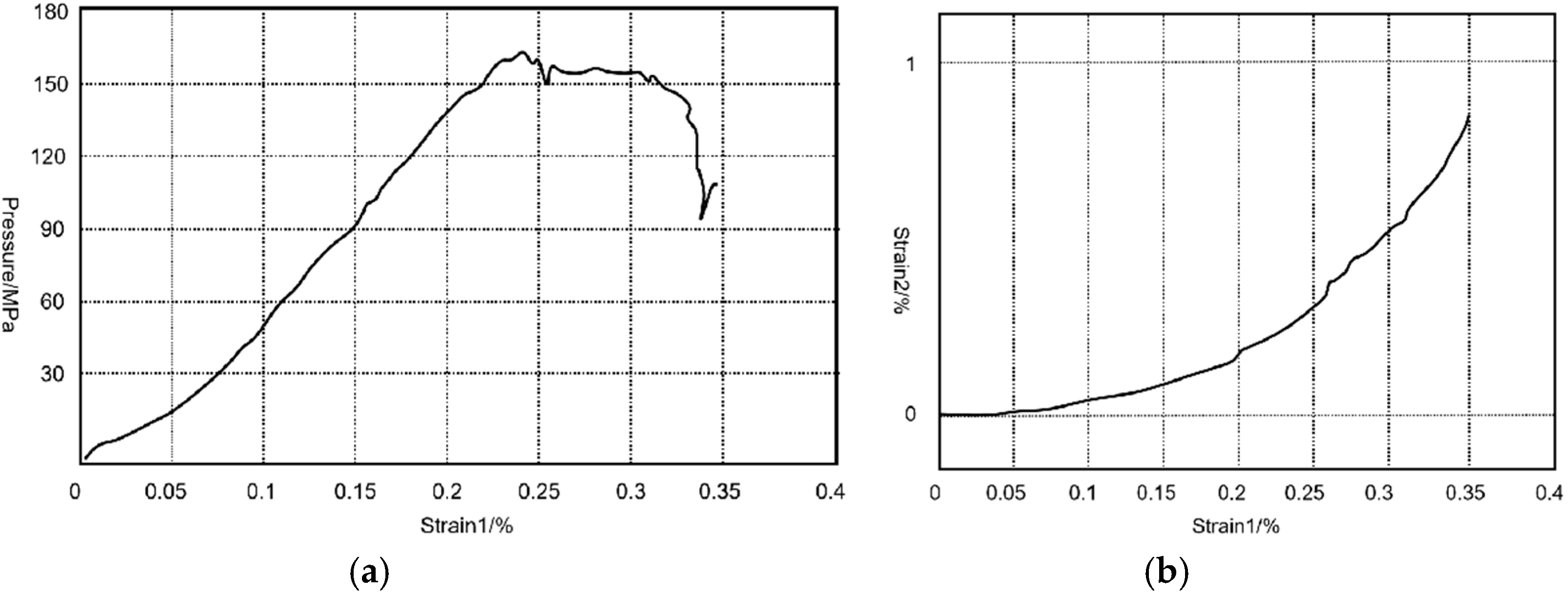
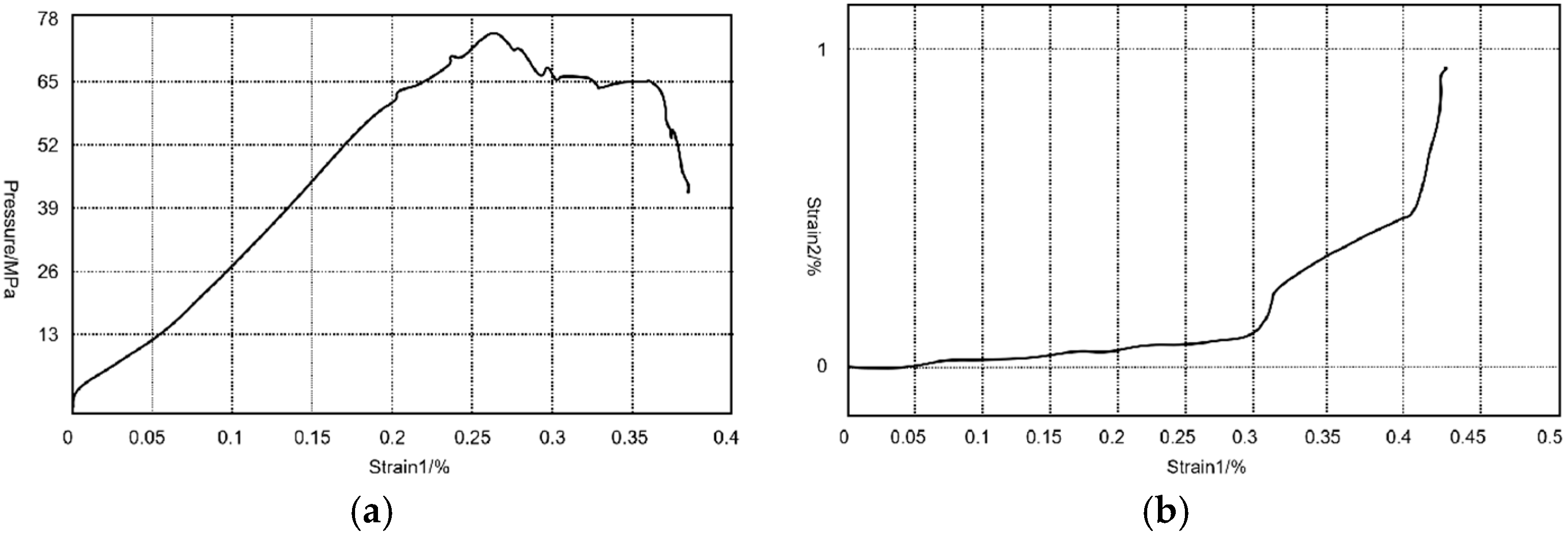
Small core columns were drilled on the whole diameter core, and triaxial compression tests were carried out before and after acid erosion to investigate the degradation effect on rocks and design the acid density. The density of the sample was 2.80 g/cm
3 by measuring the volume and mass of the small core column. Through the analysis of stress-strain curve (
Figure 2 and
Figure 3), it is found that before acid etching, the density of the sample is 2.80 g/cm
3, the porosity is 2.7%, the tensile strength is about 7 MPa, the triaxial compressive strength is 130 MPa, the elastic modulus is about 55 GPa, and the Poisson’s ratio is about 0.35. After acid etching, the density of the sample is 2.70 g/cm
3, the porosity is 3.05%, the tensile strength is about 5 MPa, the triaxial compressive strength is 77 MPa, the elastic modulus is about 18 GPa, and the Poisson’s ratio is 0.38 (
Table 2).
Based on field practice and theoretical research, the relationship between acid concentration and fracture pressure was established according to the drainage capacity of acid etching cracks [
24]: P =a − b × C
n. Where C is the concentration of acid solution (%), P is the fracture pressure (MPa), and a, b, and n are all experimental parameters. For the physical properties of dolomite, a is generally taken as 90 (MPa), b is the acid concentration influence coefficient, generally taken as 2 (MPa/%), n is the degree of nonlinearity of the fitting formula, which is generally taken as 0.6. By substituting the fracture pressure value of the sample after known acid pressing into the formula, it can be calculated that the acid concentration is about 20.72%.
In order to study the influence of acid on the reservoir rock during the on-site fracturing construction, we applied the on-site fracturing acid to the indoor experiments. (front fluid: raw acid; fracturing fluid: gelatin acid and slip water). Autogenic acid is of low friction, high corrosion inhibition, and effective induced steering function, which can effectively promote the acid flow to weak surfaces and natural crevices, forming a large area of acid erosion. The components of autogenic acid in the acidification fracturing experiments were 10% autogenic acid, 1.0% drain, 0.6% thickener, 0.5% potassium chloride, 0.6% crosslinker, and 0.05% glue breaker. Due to the existence of a coagulation agent, its viscosity becomes high, which can effectively reduce the reaction rate of acid corrosion and reduce the loss of acid filtration, resulting in long acid corrosion cracks and high crack conductivity. The components of gelatin acid in the acid-based fracturing experiment were 20% hydrochloric acid, 2.0% corrosion inhibitor, 0.6% gelatin agent, 1.0% iron ion stabilizer, 1.0% active agent, and 1.0% clay stabilizer. The above solvents of automatic acid and gelatin acid are clear water. The results of the acid solution configuration are shown in
Figure 4. According to the previously calculated acid concentration, the density of the prepared self-generated acid and gelatin acid is about 1.03 g/cm
3 and 1.1 g/cm
3. All of the above reagents was provided by the Southwest Oilfield Company of China Petroleum for on-site support of research, Chengdu China.
2.3. Acid Pressure Equipment
The experiment adopts a large-scale true three-axis acidification fracturing simulation experiment system, which was independently developed by the Rock Mechanics Laboratory of China University of Petroleum (Beijing). As shown in
Figure 4 left, the fracture cracking, steering, and extension forms of carbonate acid pressure fracture are simulated. The continuous injection of fracturing fluid can be realized by a double cylinder pump and monitoring equipment. However, the piston material in direct contact with the fracturing fluid is stainless steel. Stainless steel is relatively inert to water or silicone oil, but it is not resistant to acidic fluids. Therefore, an alternative alternating injection piston system was designed to replace the piston in the original servo control system to guarantee acid resistance (
Figure 5). There are two piston containers in the alternating injection piston system. The device can continuously or alternately inject various fracturing fluids into the rock, one may switch the piston injection pipe control valve to achieve alternating injection, without reducing the pump pressure to zero, which conforms to the actual field operation. Due to the corrosive characteristics of the acidic fluid, the two piston containers are made of Harzi alloy and can withstand good corrosion. The alternating injection piston system is shown in
Figure 6 left. During fracturing, the acidified fracturing fluid is injected into the sample shaft through the MTS supercharger-driven piston. The separator has a volume of 1000 mL and a bearing pressure of 100 MPa, which meets the simulation requirements of large underground carbonate sample injection and long fracturing time. In order to prevent shear slip, a rubber gasket was added between the pressure plate and the sample. Also, Vaseline was applied to minimize the friction between the loading template and the sample, aiming to avoid uneven stress distribution inside the sample. Compared with the conventional fracturing equipment, the temperature-controlled equipment adds an insulation partition on the inside of the surrounding pressure plate, where the heating rod is filled in the insulation partition internal measurement close to the surface of the sample. The temperature monitor probe is connected to the surface of the wellbore, and the heating temperature can reach up to 260 °C. In order to ensure the heating efficiency to prevent heat loss, the sample needs to add the surrounding pressure to ensure that the insulation partition is a close fit and install the cover plate to prevent the heat from rising. When the central shaft surface reaches the preset temperature, it indicates that the whole specimen is heated to start the experiment, as shown in
Figure 6 right. In order to balance and load the triaxial stress, the minimum horizontal stress, the maximum horizontal stress, and the vertical main stress are loaded into the design value in turn. Subsequently, the acidified fracturing fluid is pumped according to the set displacement until the sample breaks, and the sample is opened along the acid pressure crack to study the crack propagation form.
2.4. Acid Pressure Scheme
Since this experiment is carried out in the laboratory, it is necessary to simulate the actual field conditions. However, because the horizontal stress at the site is between 50 MPa and 70 MPa, it cannot be achieved under laboratory conditions. Therefore, in this study, we use the method of the similarity ratio criterion [
25,
26] for simulation. A similar method is a scientific method of extending the research results of individual phenomena (models) to similar phenomena (prototypes). The simulation experiment is to establish a certain relationship between the model and the prototype to meet the similarity requirements. If the equation analysis method of similar theory is to be applied in a study, the prerequisite is that there must be a group of differential equations describing the phenomenon and related single-value conditions. With the theoretical equations on which the 3D model is based and the single value conditions derived from the prototype and model, the experimental parameters required for the construction of the model experiment can be deduced using the similarity theory. In this study, according to the formula of similarity criterion conversion, it can be calculated that under laboratory conditions, the maximum horizontal principal stress is 28 MPa and the minimum horizontal principal stress is 23 MPa.
In this study, four groups of control tests were set up to explore the influence of different acid systems on crack propagation and acid erosion. Autobiotic acid and slip water were used as the front fluid with the gelatin acid as fracturing fluid, and the loading temperature was 100–120 °C. Based on the second theorem and crack control equation derived similar criteria, the actual formation stress conditions and construction parameters into the field of experimental scale parameters, as shown in
Table 3, determine the physical simulation test displacement of 20 mL/min (corresponding field displacement of 6 m
3/min), so as to simulate the real formation horizontal well fracturing construction.
3. Experimental Results and Analysis
3.1. Acid Pressure Crack Form
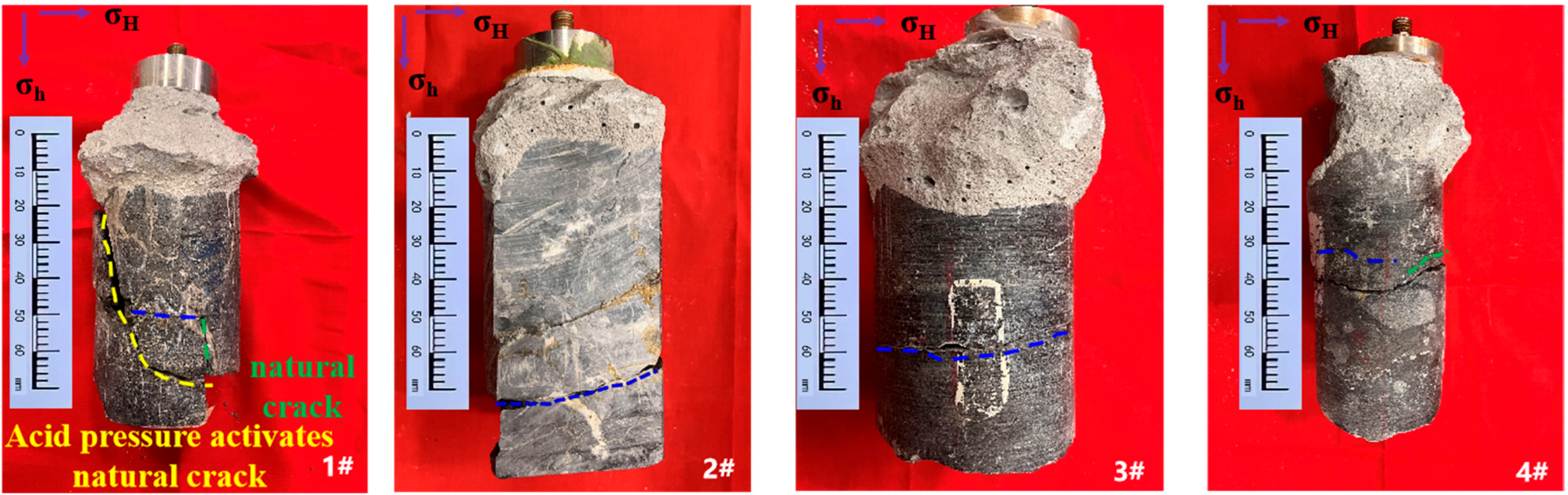
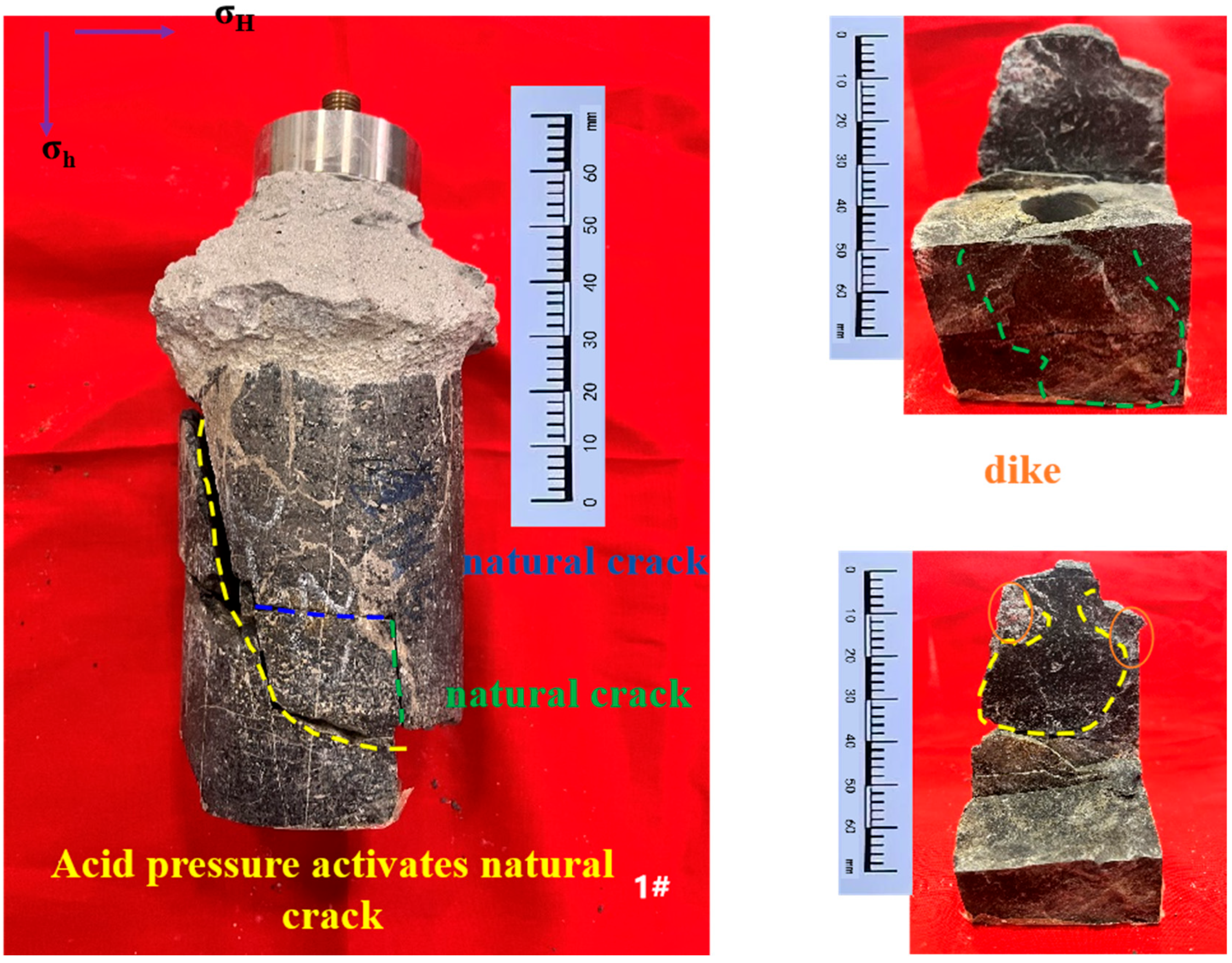
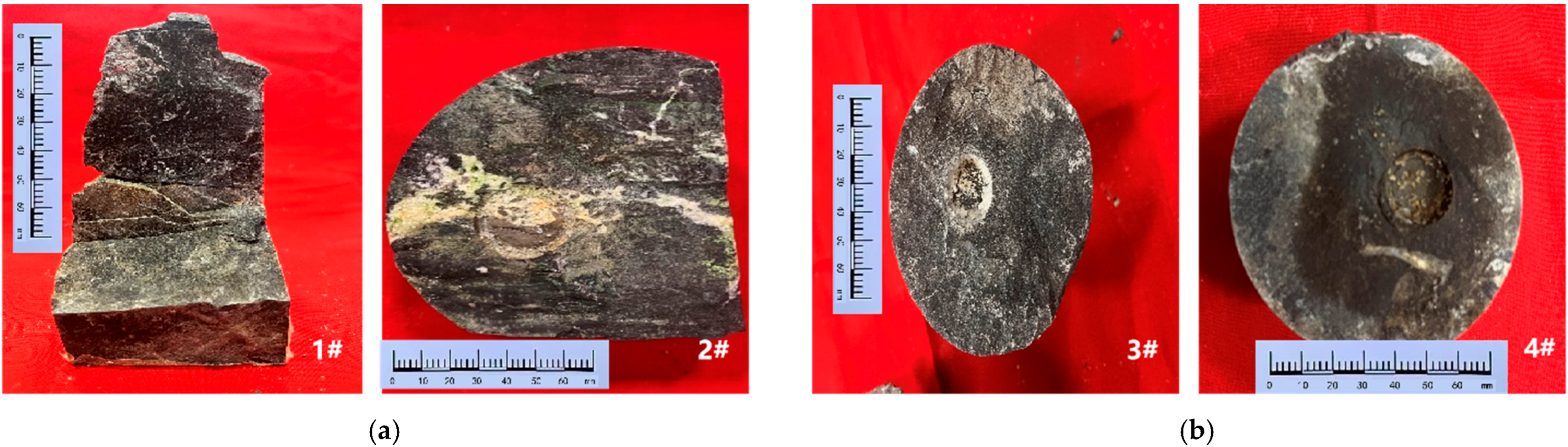
The hydraulic fractures of Sample 1 propagate along the direction of the vertical minimum main stress. In the process of crack propagation, it encounters a natural crack with a vertical inclination of 30 degrees and a vertical natural crack, forming a “spoon” seam. In Samples 2 and 3, the whole cracks propagate along the vertical minimum main stress direction to form a horizontal joint. Sample 4 cracks along the vertical minimum main stress direction and turns at an angle with the horizontal direction of 30 to form a steering horizontal seam. Natural fractures are mostly developed in the 4600 m strata of the Maokou Formation, and when the fracturing fluid system contains gelling acid, the fracture morphology is relatively complex (
Figure 7).
The acid erosion trace of the main crack in sample 1 is obvious, and the main acid erosion interface is distinctly pale yellow. The major mineral component of sample 1 is calcite, and the overall distribution of calcite veins is uneven. It is found that the acid erosion trace is concentrated on the surface of fine crystal limestone, while the acid erosion trace is rarely found in the calcite vein. The distribution of calcite veins has a certain hindering effect on the expansion of the crack. The acid erosion trace on the posterior surface of the calcite vein is significantly weaker than that of the aforementioned, and the area surrounded by the four veins is the main acid erosion area. The crack surface of sample 2 is not apparent, producing three distinct areas with varying acid erosions. Area 1 is relatively deepest-colored and has a relatively smooth surface. Areas 2 and 3 are relatively light in color with a particular granular vision. To accurately describe the crack expansion pattern, a green, fluorescent reagent was added to the acid system for calibration. The slower the flow rate of the fracturing fluid, the more obvious the green deposition is. The green sedimentary area is mainly concentrated at the calcite vein near the naked eye section and the calcite vein at the outer boundary of area 2. Little settlement was observed in Area 1, while Areas 2 and 3 contained less uniformly distributed green settlements. Cracks predominantly expand to the fine limestone, due to the larger density, less porosity, and permeability in Calcite than fine limestone, which decreases the flow rate of acid. The naked eye section of the Area 2 and 3 wellhead is surrounded by square veins, and the flow rate is significantly reduced compared with Area 1. The reaction time of acid rock is longer; thus, the roughness of the crack surface is improved (
Figure 8).
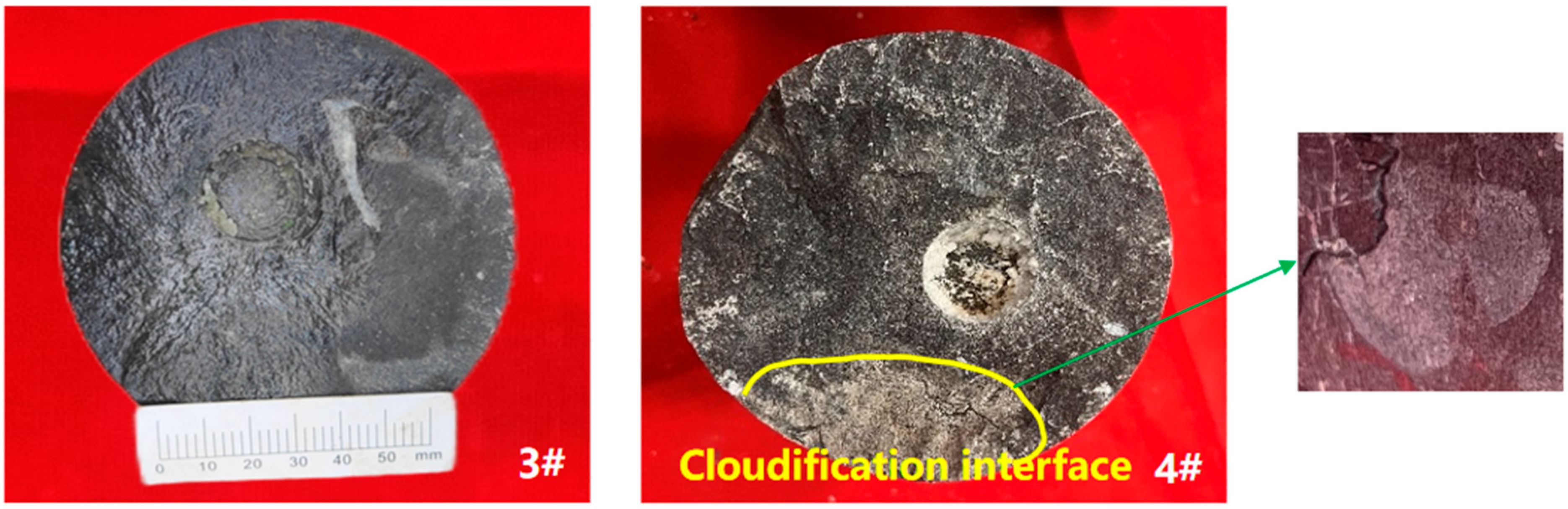
The crack surface of sample 3 is smooth, and the dolomite is evenly distributed. The intrusion and filling phenomenon of calcite veins is significantly reduced, and there is no obvious obstruction to the expansion of the acid erosion crack. Sample 4 has a rough surface and shows apparent acid erosion traces. Due to the dolomerization of hydrothermal reservoir limestone, the permeability and porosity of dolomitic limestone are significantly improved. This benefits the dissolution of cracks and holes. Due to the difference in properties between dolomized limestone and limestone, the formation of a structural weak surface between the two is conducive to the expansion of acid erosion cracks and induces the cracks to produce steering. At high temperatures, the acid reaction is strong and the gelatinous acid fluidity is poor, resulting in insufficient acid reaction. When the gelatin acid is added, the rock deterioration degree is high, and the rupture pressure decreases significantly to 6~8 MPa (
Figure 9).
3.2. Pump Pressure Curve
The pump pressure curve can directly reveal the onset pressure and onset time. Curve peaks were indirectly used to estimate the number of carbonate-activated fractures. The pump injection pressure curve at a constant pump speed is shown in
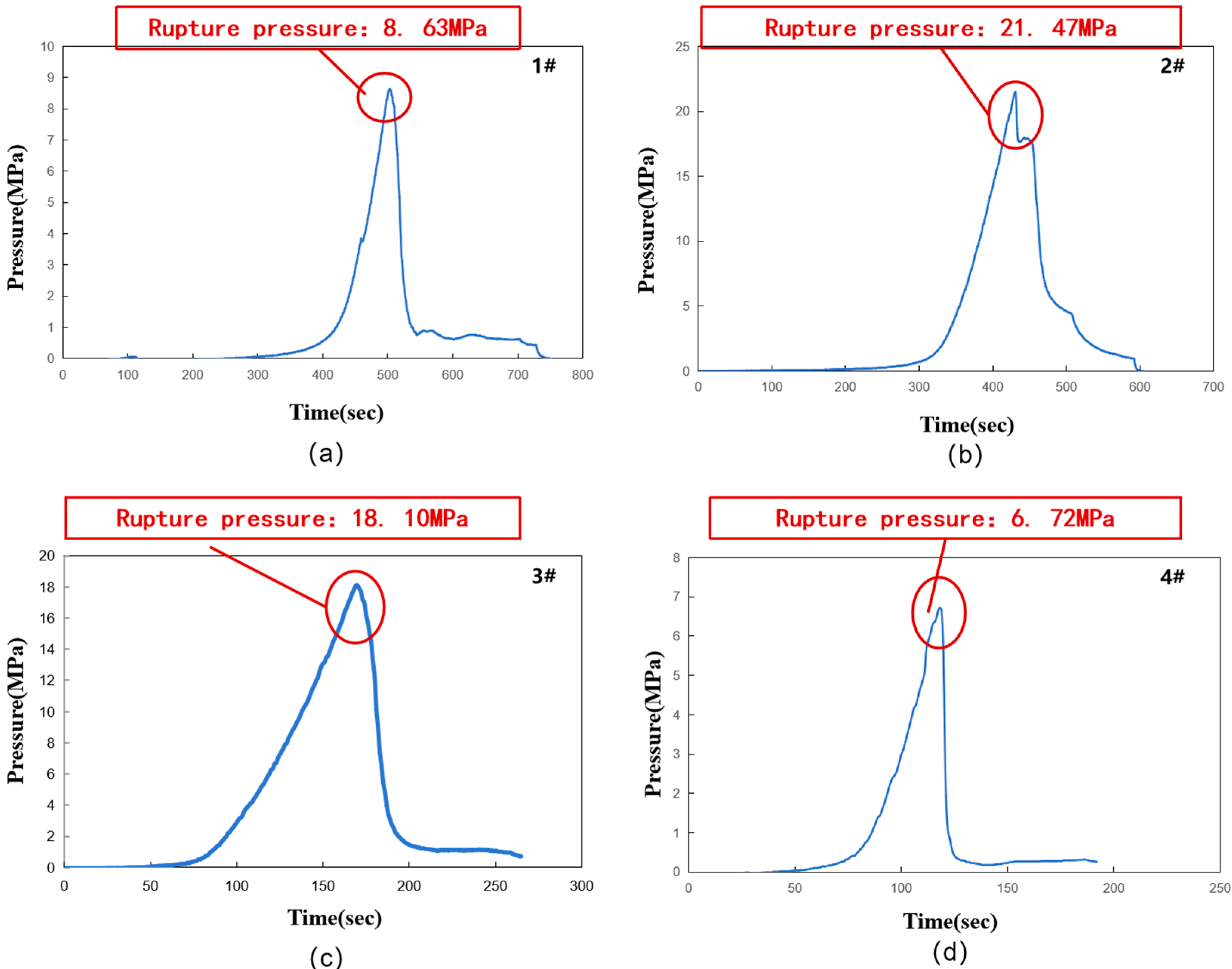
Figure 10. The injection pressure curves of 1#, 3#, and 4# are all single peaks, indicating that the sample only cracked once during acidification fracturing. The injection pressure curve of the 2# sample contains two peaks, which indicates that the sample is cracked or encountered rock veins multiple times during the fracturing process. When the sample breaks, the injection pressure significantly decreases because the acid crack volume is sufficient to accommodate the acid expansion volume. When the acid liquid flows in the seam, the influence of the friction resistance in the seam must be overcome. With the continuous erosion of the crack surface, the width of the acid pressure crack increases significantly. As shown in the experimental results of sample 1#, the complexity of the cracks increased after the acid solution came into contact with the natural cracks. Because the crack position distance of the acid pressure crack is close to the natural crack, and the acid pressure crack is instantly connected after the natural crack, so the pump pressure curve does not show apparent fluctuation. The injection pressure curve of the 2# sample shows double peaks, while the sample contains a single crack. However, in the process of fracture expansion, the pump pressure curve generally rises until the calcite surface and the pump pressure are released. After the crack of 3# sample crack expands along the maximum horizontal stress direction, the crack surface is found smooth and the friction resistance inside the joint is small. There is a cloud interface at the boundary of the 4# test sample, and the pump pressure curve rises slightly when the crack expands to the sample boundary. This is caused by the increase in the expansion resistance in the acidification crack at the cloud interface.
Different fluid treatment is the main cause of the sample fracture pressure change. For samples 1# and 4#, the action of spontaneous acid significantly reduced the cracking pressure, while the cracking pressure of samples 2# and 3# did not change significantly. The starting pressure of sample 1# is 8.63 MPa, while the starting pressure of sample 2# from the same depth reaches 21.47 MPa. The cracking pressure of sample 1# was 59.80%. Although there were calcite veins at the cracking point of sample 2#, the presence of calcite veins was not enough to significantly change the cracking pressure of the acid pressure of samples 1# and 2#. The cracking pressure of sample 3# reaches 18.10 MPa, while sample 4# from the same depth is 6.72 MPa. The cracking pressure reduction in sample 4# is 62.87%. Because the pump speed and fracturing fluid viscosity are the same, it is known that the raw acid preloading fluid can significantly reduce the cracking pressure of the carbonate sample.
3.3. Acid Fracturing Interacts with Dolomite
Calcite and dolomite structures in carbonate rocks are their important features. It is bedded in shale and gravelly in conglomerate. Therefore, these structures increase the strength and discontinuity of the limestone. The mineral content of the calcite vein and carbonate matrix is different, where the content of calcium and magnesium oxide in the matrix is higher than that of the calcite vein. During the acidic rock reaction, the oxides of calcium and magnesium first react with hydrochloric acid. Therefore, the oxides in the matrix are first consumed with the same hydrochloric acid content. Due to the difference in chemical reaction, the matrix and calcite veins generate an uneven interface. Under the action of fracturing fluid, the interface has a tendency to open. Furthermore, the presence of calcite veins will decrease the overall strength and form a discontinuous surface. As shown in
Figure 11, part of the acid flows along the calcite rock vein, and the calcite is similar to the natural fracture action, leading to the acid pressure fracture steering.
Figure 12 shows the calcite vein and the cloud action interface inside the carbonate rock. These structures hinder the expansion of the acid pressure crack. Notably, the presence of Fe
3+ and an acidic environment leads to the formation of acidic sludge. The carbonate rocks in the Qixia Formation contain Fe
3+, which provides the conditions for the formation of acidic sludge. A large amount of acidic sludge was found on the cloud action interface of the 1# and 2# samples, as shown in
Figure 12a. Compared with
Figure 12a,b, acid mud is formed at the cloud action interface, and acid mud is not formed on the calcite rock vein. Therefore, the formation of acid sludge is closely related to the acid rock reaction. This means that under acidic conditions, it is easier to form acidic sludge at the cloud action interface. In addition, it can be inferred that in the acidic environment, the larger the cloud interface area is, the more likely to form acidic sludge.
4. Discussion
At the initial stage of acid pressure, acid was gradually injected, and the formation was saturated with the acid. Rocks were deteriorated and the mechanical properties decreased such as elastic modulus. When the acid is injected for a period of time, the rock around the fracture tip deteriorates. Therefore, compared with the hydraulic fracturing cracks, the acid pressure cracks were characterized by a larger seam width, shorter seam length, and slower crack expansion. The rock on the cracked surface is corroded by the acid liquid, and the roughness degree of the crack surface rises significantly. In acid fracturing, the diversion capacity is significantly improved compared with the conventional hydraulic cracks. When the acid fluid is used as the front fluid for acidification fracturing, the rock is rapidly weakened due to the violent reaction between the acid fluid and the carbonate rock. The crack pressure is determined to be relatively low, which is conducive to the crack propagation. When guanidine is used as the front fluid, the hydraulic fracturing pressure is higher. However, the presence of the weak planes inside the shaft leads to a decrease in the cracking pressure. After the guanidine glue forms the main cracks, more natural cracks can be generated by adding acid. If the viscosity of the acid is lower than that of the guanidine, its fingers could be formed to deliver the acid away from the wellhead. Dynamic fractures are formed by opening the formation with a highly viscous non-reactive pre-hydraulic pressure, and then the fractures are dissolved by injecting acid. The pre-hydraulic opening and entering the crack reduce the temperature of the crack wall, and form a filter cake on the crack wall, reducing the subsequent acid filtration loss. The viscosity of the subsequent acid is far less than the viscosity flow process of the front fluid, so as to delay the reaction speed and filter loss speed with the crack wall to achieve the purpose of acid-deep penetration.
It can be seen that for carbonate rock, acid fracturing plays the most significant role in reducing the rupture pressure. It is better than the bubble acid treatment because its rupture pressure is the highest. The curve fluctuation of the acid pressure sample during the fracture extension stage is minimal relative to the other two, indicating that the reaction of the acid solution with the bedrock reduces the obstruction of the hydraulic fracture extension. The carbonate in the carbonate rock will react with the acid, erode the wall of the naked eye section, reduce the strength of the wall surface, and the sliding pressure fracture can reduce the rupture pressure. However, acid hydraulic cracking was used without acid foaming treatment, and the acid solution mainly interacted with carbonate rocks in the process of fracture cracking and propagation, and this weakening effect was more obvious than that of bubble acid treatment. For the carbonate reservoir with high porosity, the acid fluid will selectively enter the larger pores of the rock and expand the pores through the acid rock reaction, forming a higher diversion channel. Once the hole is formed, it will control the loss of the entire surface of the crack. For the fractured carbonate reservoir, the acid into the reservoir hole will increase the filter loss; on the other hand, the acid into the natural crack will increase the crack width and aggravate the acid leakage. There are few studies on hole expansion and filtration loss when considering acid fracture expansion. Acid liquid enters the hole and inside the crack, resulting in a sharp decrease in the net pressure in the crack. When the net fracture pressure is below the subcritical condition, the crack will not extend. Although the acid rock reaction can reduce the difficulty of fracture expansion, the phenomenon of acid filtration loss cannot be ignored. Therefore, the acid fracturing seam scale is always smaller than the hydraulic fracturing seam scale.
Changes in rock volume can also cause changes in the pump pressure. When the acid is injected into the shaft, the acid rock reaction inevitably occurs, which will increase the volume of the acid rupture, leading to a decrease in the pump pressure. However, because the acid rock reaction will produce gas, which will occupy the volume of the crack, the pump pressure may be higher. Furthermore, acid will drive crack expansion, which will help to generate a larger crack volume. Therefore, the pump injection pressure fluctuation caused by the acid rock reaction can be either positive or negative, and it is determined by the absolute volume change. When the absolute volume change is positive, pressure fluctuations create additional pressure on the pump injection pressure. Otherwise, the pump injection pressure will decrease. In future studies, a functional relationship between pump injection pressure and fracturing volume could be considered. During acid pressure, carbonate rocks are dissolved and eroded by depth, meaning that the fracking volume also includes volumes beyond the crack. Even if the rock mass is dissolved, natural gas or oil may not necessarily come out of the seepage channel. Thus, the concept of percolation probability can be introduced into the model to calculate the additional yield volume for the acid pressure or acidification process.
5. Field Application
In the on-site fracturing operations of oilfields, well PY5 adopted a multi-step injection scheme to achieve optimal results (
Figure 13).
Firstly, in the initial stage of fracturing, 80 cubic meters of self-generated acid was injected to reduce the pressure drop to 20 MPa, successfully unblocking the near-well end and significantly reducing the formation pollution. Then, the gel acid system was converted, and 20 cubic meters of gel acid was injected to successfully communicate the small-scale fractures and reduce the pressure drop to 1 MPa.
The following step involved reintroducing gelled acid into the operation. Initially, 180 cubic meters of gelled acid were injected. During the migration of the acid fluid, fractures and cavities were continuously interconnected, with the pressure drop controlled at 2.5 MPa. To augment the fracture length and the roughness of the fracture surface, 50 cubic meters of in situ acid and 140 cubic meters of gelled acid were then injected. Subsequently, the pump was stopped to allow the acid fluid to migrate slowly. Eventually, the shut-in pressure reached 37.9 MPa, and the pressure drop rate was 0.09 MPa/min.
After the pump had been stopped for a certain period, it was restarted. A total of 80 cubic meters of in situ acid and 20 cubic meters of gelled acid were successively injected, effectively eliminating near-well pollution and connecting small-scale fractures and cavities. However, when the oil pressure suddenly dropped upon reaching 105 MPa, high-viscosity gelled acid was employed as the fracturing fluid. After continuously injecting 160 cubic meters of gelled acid, the oil pressure reached 90 MPa, with a pressure drop of only 3.45 MPa.
Finally, 60 cubic meters of in situ acid was injected to connect small-scale fractures and cavities, and then the fluid was switched to gelled acid to displace the drag-reducing water. The shut-in pressure finally stabilized at 46 MPa, and the pressure drop rate was 0.07 MPa/min. This series of schemes involving the alternate injection of different acid fluids effectively connected the reservoir fractures and cavities and enhanced the roughness of the fracture surface, ultimately fulfilling the expected operational objectives.
During the on-site fracturing process, injecting gelled acid first to remove blockages and pollution, and then switching to an in situ acid system to connect small-scale fractures and cavities can effectively increase the fracture length and the roughness of the fracture surface. This is consistent with the expansion and stimulation effects of fractures under the action of acid in experiments.
Both experimental and on-site fracturing processes have demonstrated the advantages of alternately injecting different types of acid fluids. Stopping the pump during the migration of the acid fluid to reserve sufficient acid etching reaction time can improve the effectiveness of connecting fractures and cavities. Meanwhile, by adjusting the injection sequence and the acid fluid system, oil pressure fluctuations and drag-reducing water issues can be effectively controlled.
The pressure drop rate in acid fracturing experiments is closely related to that in on-site fracturing operations. A lower pressure drop rate in experiments usually indicates a better effect of formation stimulation and fracture expansion by acid fluids, and the changes in the pressure drop rate during on-site fracturing operations also reflect the reactions and effects of the formation under the action of acid fluids.
The results of experiments and on-site fracturing indicate that through rational selection of acid fluid systems, optimization of injection sequences, and control of pressure drop rates, effective stimulation and connection of formation fractures can be achieved, enhancing the efficiency and success rate of oilfield fracturing operations.
6. Conclusions
In this paper, true triaxial physical simulation experiments were carried out on carbonate rock samples under different acid systems. The fracture characteristics and pump pressure curves of carbonate rock after acid pressure were compared and analyzed, and the following conclusions were obtained:
- (1)
After the carbonate rock is subjected to acid fracturing using a “self-generated acid + gel acid” system, the fracture pressure drops significantly by up to 60%. The morphology of the acid-eroded fractures becomes more complex, with an increase in geometric complexity of about 28% compared to a single acid solution system. It is prone to form three-dimensional “spoon” shaped fractures, and the surface of the acid-eroded fractures shows light yellow acid erosion marks. Analysis of the acid erosion marks indicates that the erosion depth on the fracture surface reaches 0.8–1.2 mm, which is deeper than the 0.2 mm erosion depth achieved with a single system.
- (2)
Acid solution is difficult to penetrate randomly distributed calcite veins with a low porosity and permeability structure. When the fracture meets the calcite vein, the penetration rate of acid solution drops sharply to 15–20% of the initial value, resulting in a reduction of about 62% of the acid erosion area in the limestone section behind. The acid erosion traces in the limestone behind the calcite vein are significantly reduced. The acid erosion cracks are easy to open on the weak surface between dolomite and limestone, causing the fracture to turn.
- (3)
The area where the acid liquid acts on the matrix is mainly concentrated in the well-hole area, and the etching effect is not obvious. However, the action area of the autologous acid and gelatinate acid system and the matrix is larger, the section etching degree is deeper, and the weakening effect is better.
- (4)
The results of field engineering and experiment are consistent, and injecting authigenic acid first in the process of reservoir reconstruction is helpful to remove pollution. The recovery rate of near-well permeability is more than 85% with pre-generated acid. Reinjection of gelled acid can effectively communicate the natural weak surface and increase the complexity of cracks. The average daily oil production of the completed well was increased from 7.8 m3 to 22.5 m3, and the increase factor reached 2.88.
In this paper, we studied the expansion laws of acid etching fractures in different rock types and structures under different acid solutions. Therefore, the acid concentration, injection displacement, and confining pressure were selected according to the actual engineering parameters of the oilfield site in the central block of the Sichuan Basin. The control variables have not changed. In the future, we will carry out more detailed studies on the influence of acid concentration on the initiation and extension of carbonate fractures, the relationship between pump pressure, acid concentration, and fracture initiation in carbonate rocks, and the influence of porosity and dissolution rate in carbonate rocks.


 ,
, 


