
Adaptability Evaluation of Hybrid Riser-Based Riserless Mud Recovery System for Deepwater Natural Gas Hydrate Exploration and Development

 ,
,
Abstract
1. Introduction
- (1)
- Methane Emissions and Climate Impacts: NGH extraction may release substantial quantities of methane, a potent greenhouse gas with a 100-year global warming potential (GWP100) that is 28–36 times greater than that of CO2 [15]. These emissions could significantly impact both marine and atmospheric systems [16], potentially exacerbating climate change through positive feedback mechanisms. Methane release occurs through two principal mechanisms: (1) the direct dissociation of hydrate structures and (2) the formation of migration pathways through compromised sediment seals. This leakage may influence large-scale ocean circulation patterns and increase the frequency of extreme weather events [17].
- (2)
- Geomechanical Stability Concerns: Hydrate dissociation alters sediment’s mechanical properties by reducing the cementation strength and effective stress while increasing the porosity [18]. Such changes may compromise the seabed stability, potentially triggering submarine landslides that could damage critical marine infrastructure and benthic ecosystems [19].
- (3)
2. Technical Foundation of the Innovative Integrated System Technology
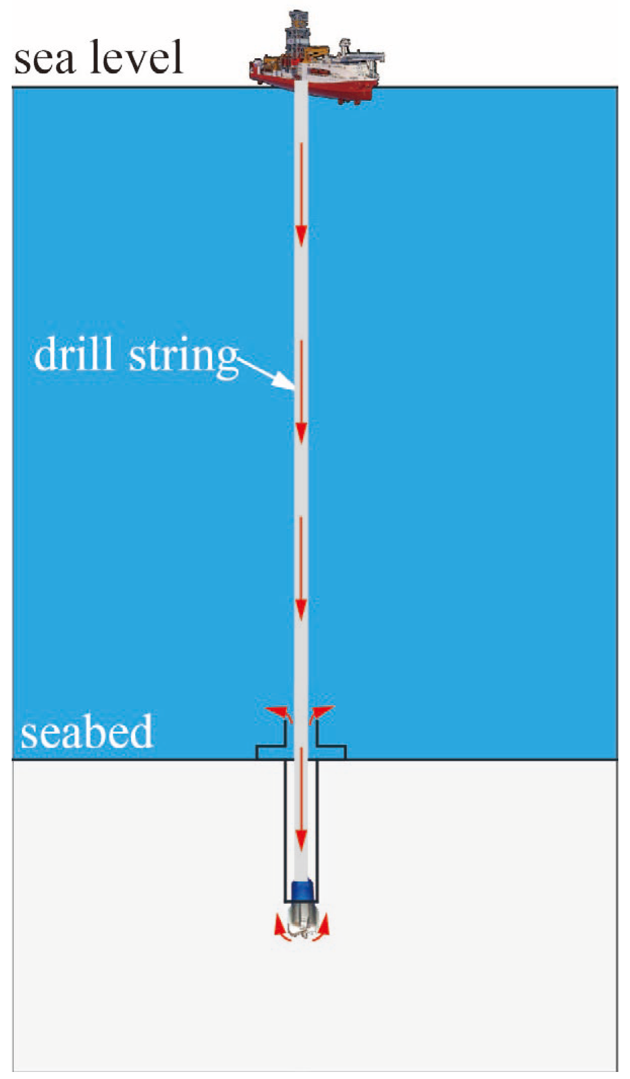
2.1. Riserless Drilling for Natural Gas Hydrates
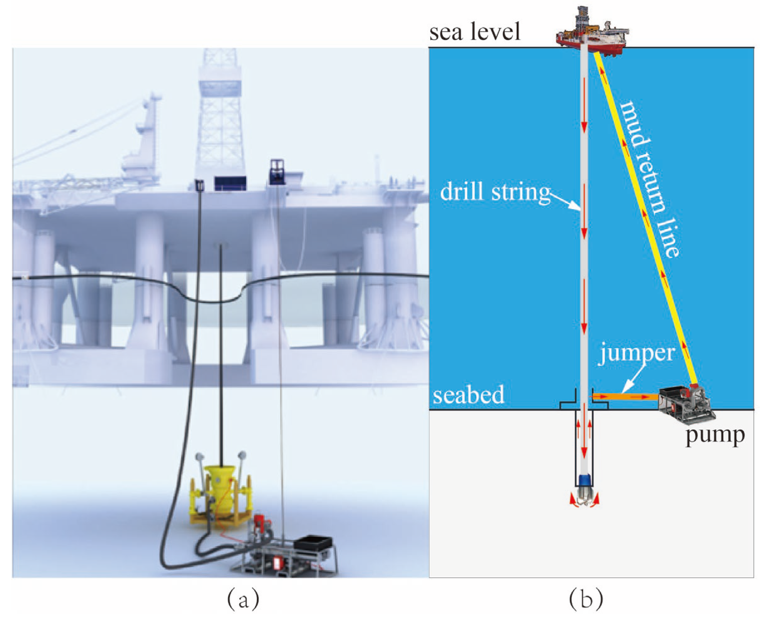
2.2. Closed-Loop Drilling with Riserless Mud Recovery System
- (1)
- Dual-gradient drilling optimization: Utilizing the seawater–mud interface above the mudline, the system maintains optimal wellbore pressure profiles, effectively managing narrow drilling windows while mitigating kick risks.
- (2)
- Closed-loop fluid circulation: Dedicated return pipelines enable direct mud recycling to surface facilities, with (a) an approximately 70–80% reduction in total fluid consumption in tophole drilling; (b) the complete elimination of seabed discharge and the associated biotoxicity.
- (3)
- Regulatory compliance: It fully satisfies the zero-discharge requirements for offshore operations.
- (4)
- Operational efficiency: It demonstrates a reduction in casing strings and the operation period.
- (5)
- Early hazard detection: Enhanced monitoring capabilities enable the quick identification of wellbore influxes by monitoring subsea modules, as well as an improved response to blowouts/losses through real-time diagnostics.
- (6)
- Well design advantages: It facilitates optimized casing programs and extended casing setting depths (by approximately 300–500 m in field applications).
- (1)
- Multi-stage mud lift system—series-connected pump units for reliable mud return;
- (2)
- Specialized casing design—a 193.7 mm diameter with vortex-induced vibration (VIV) suppression;
- (3)
2.3. Hybrid Riser for Production
3. Hybrid Riser-Based Riserless Mud Recovery System
3.1. Technical Framework
3.1.1. Main Structural Forms
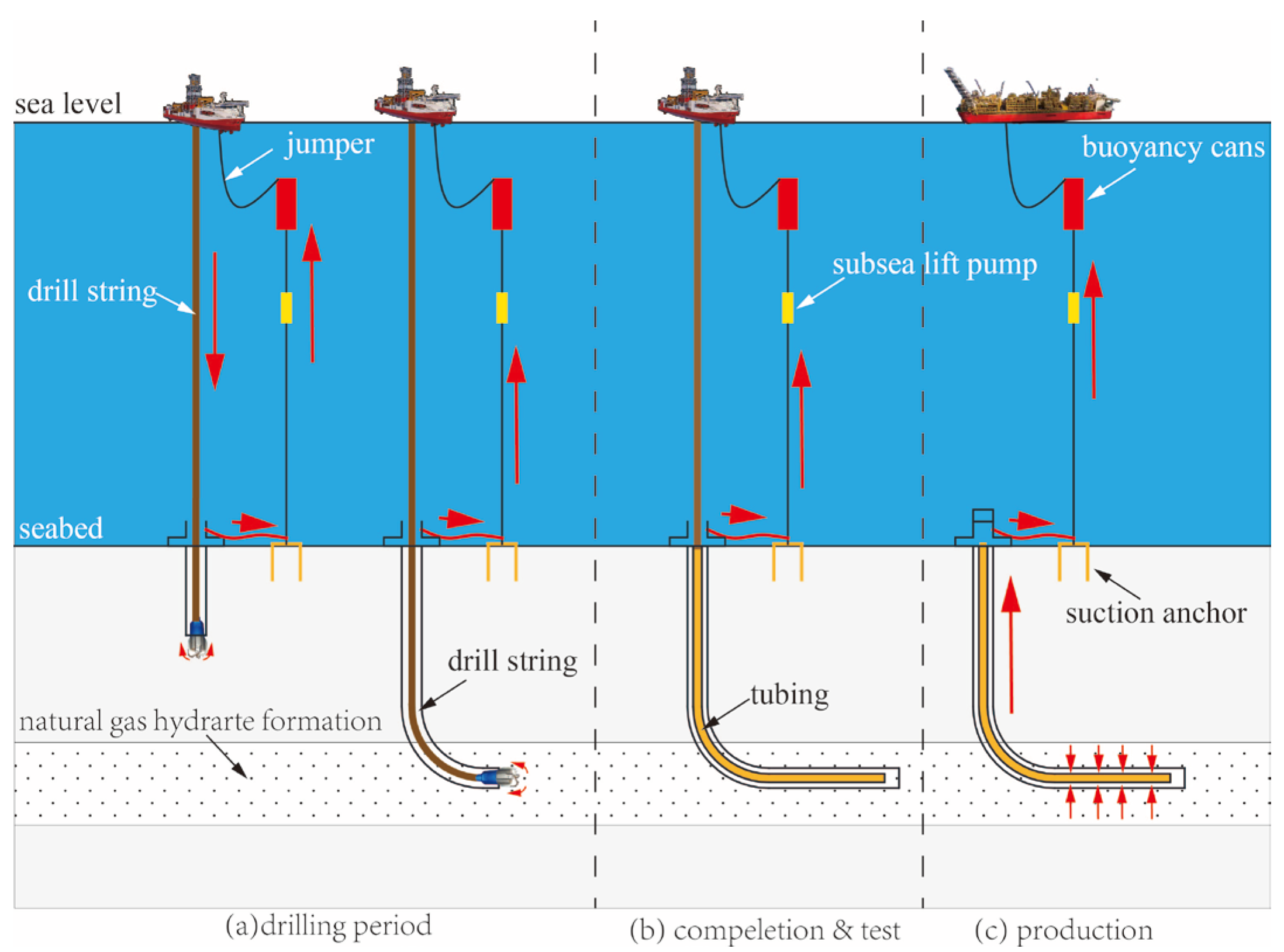
3.1.2. Operation Process, from Drilling to Production
- (1)
- Drilling
- (2)
- Completion and test
- (3)
- Production
3.2. Characteristic Analysis
3.2.1. Mechanical Decoupling
3.2.2. Buoyancy Control for Top Tension
3.2.3. Strings Spacing Control
3.2.4. Adaptation to Ultra-Deepwater Conditions
3.2.5. Multi-Stage Pump Suspension Adaptation
3.2.6. Pre-Installation
3.2.7. Rapid Construction
4. Structural Feasibility Analysis
4.1. Model Establishment
4.2. Load Analysis
4.2.1. Bending, Tension, and Stress
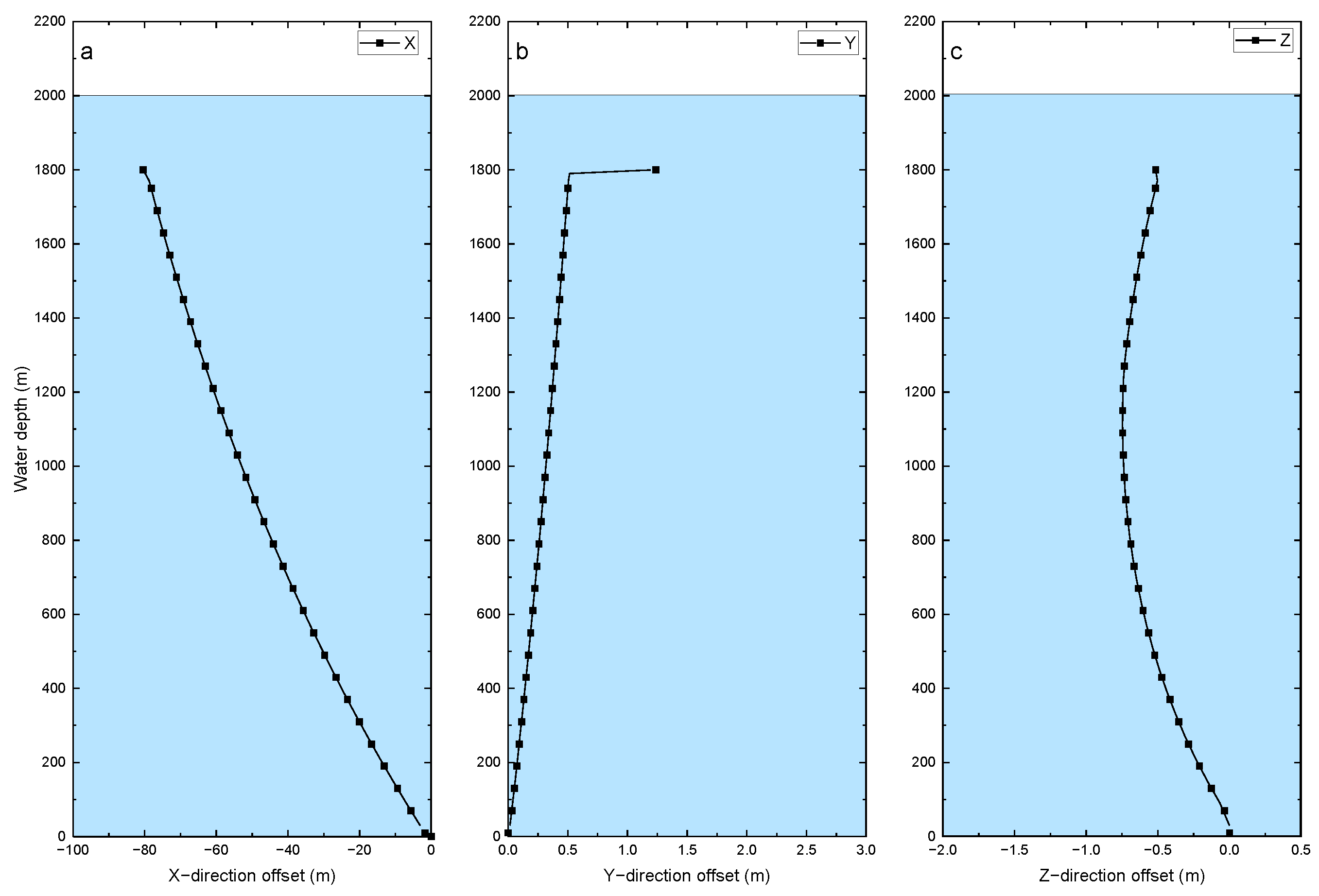
4.2.2. Longitudinal and Lateral Bending Deformation
4.2.3. Motion Behavior of Submerged Buoyancy Cans
5. Key Parameter Analysis and Discussion
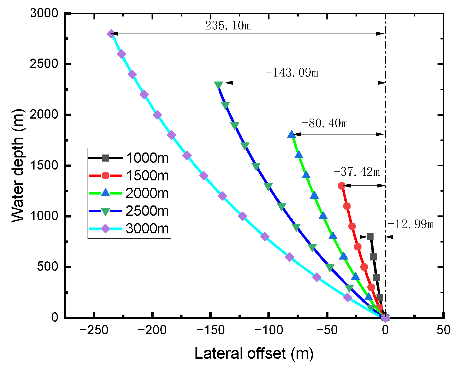
5.1. Water Depth
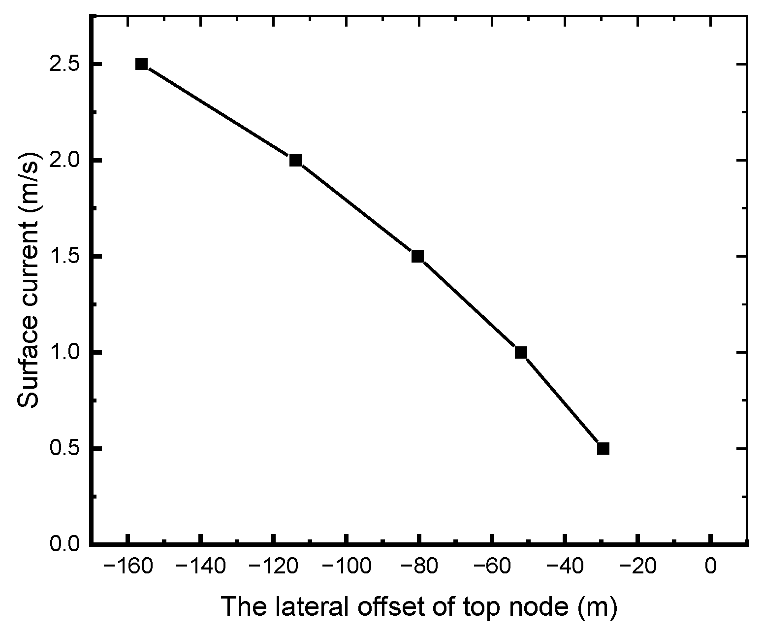
5.2. Current
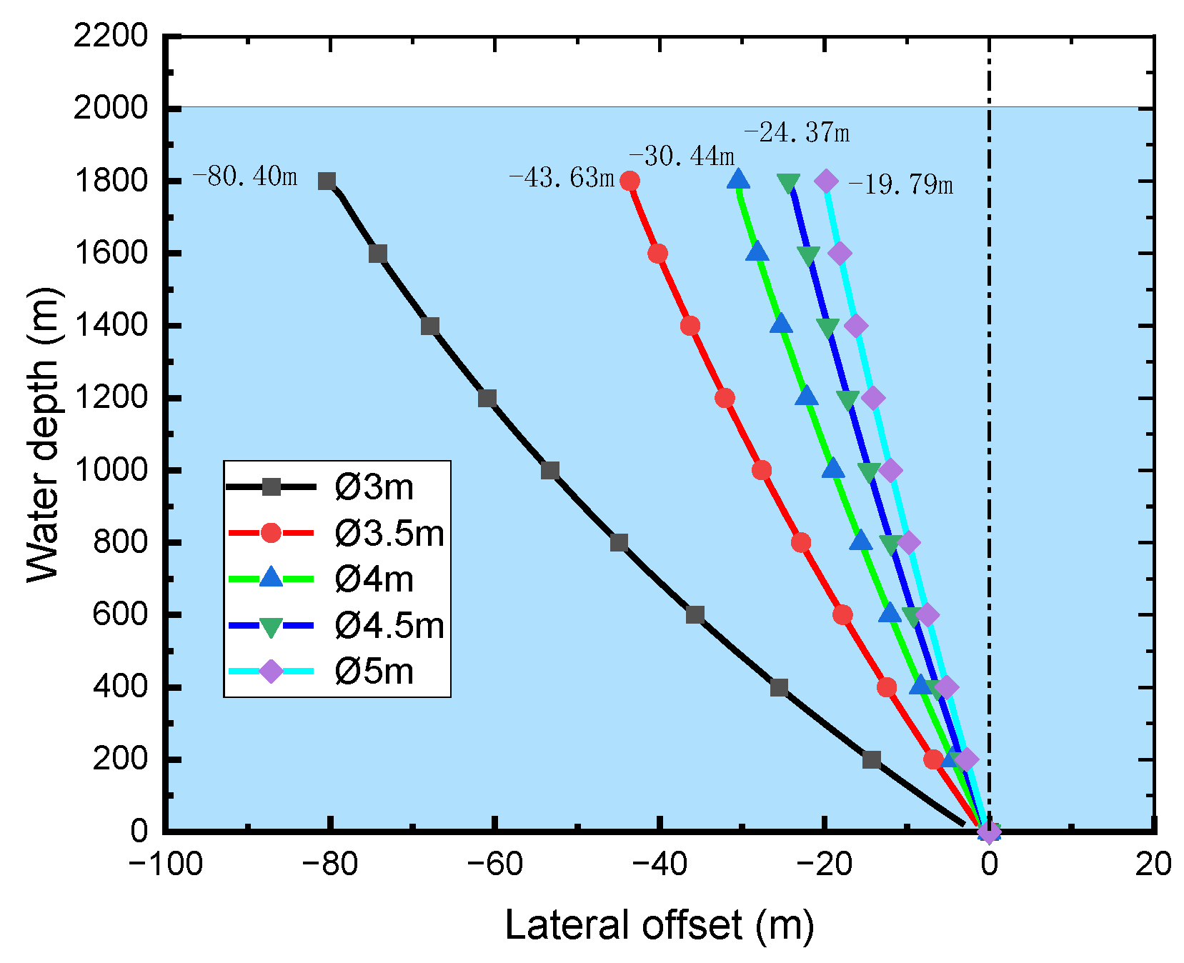
5.3. Top Tension
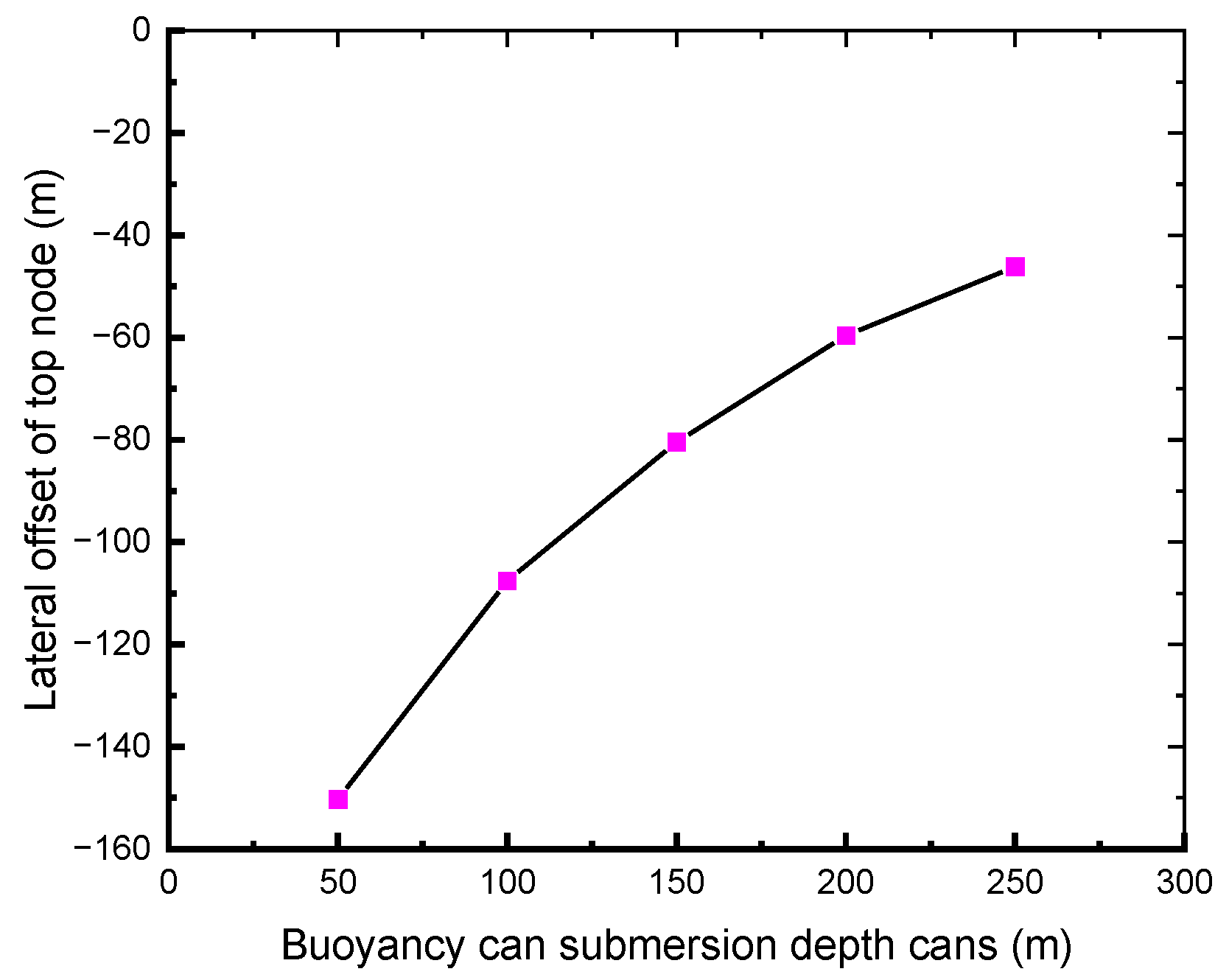
5.4. Submerged Depth of Buoyancy Cans
6. Conclusions
- (1)
- The proposed system maintains mechanical decoupling and structural stability under water depths ranging from 1000 to 3000 m, with 97% operational reliability in the modeled metocean conditions.
- (2)
- Ensuring the safe and stable operation of marine mud return pipeline systems requires the comprehensive collection and analysis of physical oceanographic data to accurately characterize the spatiotemporal current distributions in the operational area.
- (3)
- The strategic scheduling of construction activities during periods of reduced current velocity and directional stability would serve to minimize hydrodynamic impacts on the pipeline’s integrity.
Author Contributions
Funding
Data Availability Statement
Conflicts of Interest
References
- Klauda, J.B.; Sandler, S.I. Global Distribution of Methane Hydrate in Ocean Sediment. Energy Fuels 2005, 19, 459–470. [Google Scholar] [CrossRef]
- Boswell, R.; Collett, T.S. Current perspectives on gas hydrate resources. Energy Environ. Sci. 2011, 4, 1206–1215. [Google Scholar] [CrossRef]
- Liang, J.Q.; Ning, F.L.; Zhang, R.W.; Liang, Q.Y.; Hu, G.W.; Yang, W. Advances and Future Perspectives in Offshore Gas Hydrate Exploration & Production. Acta Gologica Sin. 2024, 98, 1–8. (In Chinese) [Google Scholar]
- Dallimore, S.R.; Collett, T.S.; Taylor, A.E.; Uchida, T.; Weber, M.; Chandra, A.; Mroz, T.H.; Caddel, E.M.; Inoue, T. Summary and implications of the Mallik 2002 gas hydrate production research well program. In Scientific Results from the Mallik Gas Hydrate Production Well Program; Bulletin of the Geological Survey of Canada: Mackenzie Delta, NT, Canada, 2005; Volume 585, pp. 1–14. [Google Scholar]
- Yamamoto, K. Overview and introduction: Pressure core-sampling and analyses in the 2012-2013 MH21 offshore test of gas production from methane hydrates in the eastern Nankai Trough. Mar. Pet. Geol. 2015, 66, 296–309. [Google Scholar] [CrossRef]
- Zhang, W.; Shao, M.; Yao, S. Analysis of development process of natural gas hydrate in Japan and its enlightenment to China. Sino-Glob. Energy 2023, 28, 15–22. [Google Scholar]
- Zhang, W.; Shao, M.; Wang, H. The latest progress in the research and development of pro-filling type gas hydrate in Japan. Mar. Geol. Front. 2025, 41, 1–11. [Google Scholar]
- Gajanan, K.; Ranjith, P.G.; Yang, S.Q.; Xu, T. Advances in research and developments on natural gas hydrate extraction with gas exchange. Renew. Sustain. Energy Rev. 2024, 190, 114045. [Google Scholar] [CrossRef]
- Li, X.; Zhang, Y.; Yin, H. Application of Horizontal Multilateral Well Drilling Technology in Natural Gas Hydrate Production Testing. Explor. Eng. (Rock Soil Drill. Tunneling) 2017, 44, 13–17. [Google Scholar]
- Li, J.; Ye, J.; Qin, X.; Qiu, H.J.; Wu, N.Y.; Lu, H.L.; Xie, W.W.; Lu, J.A.; Peng, F.; Xu, Z.Q.; et al. The first offshore natural gas hydrate production test in South China Sea. China Geol. 2018, 1, 5–16. [Google Scholar] [CrossRef]
- Ye, J.; Qin, X.; Xie, W.; Lu, H.-L.; Ma, B.-J.; Qiu, H.-J.; Liang, J.-Q.; Lu, J.-A.; Kuang, Z.-G.; Lu, C.; et al. The second natural gas hydrate production test in the South China Sea. China Geol. 2020, 3, 197–209. [Google Scholar] [CrossRef]
- Li, B.; Kou, B.; Li, B.; Li, J.; Zeng, J.; Niu, Q.L.; Shao, Y.T.; Zhang, K.W.; Yu, H.Y.; Wang, Y.S. Application of wellhead suction anchor technology in the second production test of natural gas hydrates in the South China Sea. China Geol. 2022, 5, 293–299. [Google Scholar]
- Zeng, J.; Xie, W.; Kou, B.; Lu, J.-A.; Li, X.-C.; Cai, D.-J.; Shi, H.-X.; Zhang, K.-W.; Liu, H.-Q.; Li, J.; et al. Lateral bearing characteristics of subsea wellhead assembly in the hydrate trial production engineering. China Geol. 2023, 6, 455–465. [Google Scholar]
- Sloan Jr, E.D.; Koh, C.A. Clathrate Hydrates of Natural Gases, 3rd ed.; CRC Press: Boca Raton, FL, USA, 2008. [Google Scholar]
- Intergovernmental Panel on Climate Change. Climate Change 2021—The Physical Science Basis. Contribution of Working Group I to the Sixth Assessment Report of the Intergovernmental Panel on Climate Change; Cambridge University Press: Cambridge, UK, 2023. [Google Scholar]
- Shakhova, N.; Semiletov, I.; Leifer, I.; Sergienko, V.; Salyuk, A.; Kosmach, D.; Chernykh, D.; Stubbs, C.; Nicolsky, D.; Tumskoy, V.; et al. Ebullition and storm-induced methane release from the East Siberian Arctic Shelf. Nat. Geosci. 2014, 1, 64–70. [Google Scholar] [CrossRef]
- Ruppel, C.D.; Kessler, J.D. The interaction of climate change and methane hydrates. Rev. Geophys. 2016, 55, 126–168. [Google Scholar] [CrossRef]
- Xu, W.; Germanovich, L.N. Excess pore pressure resulting from methane hydrate dissociation in marine sediments. J. Geophys. research. Solid Earth JGR 2006, 111, B1. [Google Scholar] [CrossRef]
- Kvenvolden, K.A. Gas hydrates—Geological perspective and global change. Rev. Geophys. 1993, 31, 173–187. [Google Scholar] [CrossRef]
- Boetius, A.; Wenzh, F.F. Seafloor oxygen consumption fuelled by methane from cold seeps. Nat. Geosci. 2013, 6, 725–734. [Google Scholar] [CrossRef]
- Biastoch, A.; Treude, T.; Rüpke, L.H. Rising Arctic Ocean temperatures cause gas hydrate destabilization and ocean acidification. Geophys. Res. Lett. 2011, 38, L08602. [Google Scholar] [CrossRef]
- OSPAR Convention. Convention for the Protection of the Marine Environment of the North-East Atlantic. 1998. Available online: https://www.ospar.org/convention/text (accessed on 25 March 1998).
- Cohen, J.H.; Kleppe, J.; Grønås, T.; Martin, T.B.; Tveit, T.; Gusler, W.; Christian, C.F.; Golden, S. Gulf of Mexico’s First Application of Riserless Mud Recovery for Top-Hole Drilling—A Case Study. In Proceedings of the Offshore Technology Conference, Houston, TX, USA, 3–6 May 2010. [Google Scholar] [CrossRef]
- Michael, V.R. Advances in riserless drilling pushing the deepwater surface string envelope. Offshore: Inc. Oilman 2001, 61, 56–58. [Google Scholar]
- Eggemeyer, J.C.; Akins, M.E.; Brainard, R.R.; Judge, R.A.; Peterman, C.P.; Scavone, L.J.; Thethi, K.S. SubSea MudLift Drilling: Design and Implementation of a Dual Gradient Drilling System. In Proceedings of the SPE Annual Technical Conference and Exhibition, New Orleans, LO, USA, 30 September–3 October 2001. [Google Scholar] [CrossRef]
- Schumacher, J.P.; Dowell, J.D.; Ribbeck, L.R.; Eggemeyer, J.C. Subsea Mudlift Drilling: Planning and Preparation for the First Subsea Field Test of a Full-Scale Dual Gradient Drilling System at Green Canyon 136, Gulf of Mexico. In Proceedings of the SPE Annual Technical Conference and Exhibition, New Orleans, LO, USA, 30 September–3 October 2001. [Google Scholar] [CrossRef]
- Roller, P.R. Riserless Drilling Technique Saves Time and Money by Reducing Logistics and Maximizing Borehole Stability. In Proceedings of the SPE/IADC Drilling Conference, Amsterdam, The Netherlands, 19–21 February 2003. [Google Scholar] [CrossRef]
- Schubert, J.J.; Juvkam-Wold, H.C.; Choe, J. Well Control Procedures for Dual Gradient Drilling as Compared to Conventional Riser Drilling. SPE Drill. Complet. 2003, 21, 287–295. [Google Scholar] [CrossRef]
- Stave, R.; Fossli, B.; Endresen, C.; Rezk, R.H.; Tingvoll, G.I.; Thorkildsen, M. Exploration Drilling with Riserless Dual Gradient Technology in Arctic Waters. In Proceedings of the OTC Arctic Technology Conference, Houston, TX, USA, 10–12 February 2014. [Google Scholar] [CrossRef]
- Stave, R.; Farestveit, R.; Hyland, S.; Rochmann, P.; Rolland, N. Demonstration and Qualification Of A Riserless Dual Gradient System. In Proceedings of the Offshore Technology Conference, Houston, TX, USA, 2–5 May 2005. [Google Scholar] [CrossRef]
- Alford, S.E.; Asko, A.; Campbell, M.; Aston, A.M.; Kvalvaag, E. Silicate-Based Fluid, Mud Recovery System Combine to Stabilize Surface Formations of Azeri Wells. In Proceedings of the SPE/IADC Drilling Conference, Amsterdam, The Netherlands, 23–25 February 2005. [Google Scholar] [CrossRef]
- Enhanced-Drilling, RMR® System—Drilling Technology for Top Holes|Enhanced Drilling. Available online: https://www.enhanced-drilling.com/rmr-solution (accessed on 11 March 2025).
- Frøyen, J.; Rommetveit, R.; Jaising, H.; Stave, R.; Rolland, N.L. Riserless Mud Recovery (RMR) System Evaluation for Top Hole Drilling with Shallow Gas. In Proceedings of the SPE Russian Oil and Gas Technical Conference and Exhibition, Moscow, Russia, 3–6 October 2006. [Google Scholar] [CrossRef]
- Vernon, R.; Buchan, S.; Halland, M. Riserless mud system solves North Sea drilling problem. Offshore Inc. Oilman 2006, 66. Available online: https://www.offshore-mag.com/business-briefs/equipment-engineering/article/16754250/riserless-mud-system-solves-north-sea-drilling-problem (accessed on 11 March 2025).
- Hannegan, D.; Stave, R. The time has come to develop riserless mud recovery technology’s deepwater capabilities. Drill. Contract. 2006, 62, 50–54. [Google Scholar]
- He, G.; Xu, B.; Chen, H.; Qin, R.; Li, C.; Yin, G. Study of the Relationships among the Reverse Torque, Vibration, and Input Parameters of Mud Pumps in Riserless Mud Recovery Drilling. Appl. Sci. 2023, 13, 11878. [Google Scholar] [CrossRef]
- Vernon, R.; Buchan, S.; Halland, M.; Hewson, J. Riser-Less Mud Recovery Solves Top-Hole Drilling Problems; Society of Petroleum Engineers: Houston TX, USA, 2008; SPE111422-MS. [Google Scholar]
- Roveri, F.E.; Filho, A.G.; Mello, V.C.; Marques, L.F. Crude Export Riser—1: Hybrid riser application provides deepwater crude export solution. Oil Gas J. 2008, 106, 58–65. [Google Scholar]
- Kang, Z.; Jia, L.; Sun, L. Design and analysis methodology of Single line offset riser buoyancy can. Shipbuild. China 2011, 52, 118–129. [Google Scholar]
- Kang, Z.; Sun, L.; Sha, Y. A review of hybrid tower riser. Ship Ocean Eng. 2011, 40, 174–179. [Google Scholar]
- Romagnoli, R.; Carpignano, A. Hybrid Riser Risk Analysis in Deepwater Production Contexts. In Proceedings of the Offshore Mediterranean Conference and Exhibition, Ravenna, Italy, 28–30 March 2001. OMC-2001-060. [Google Scholar]
- Petruska, D.J.; Zimmermann, C.A.; Krafft, K.M.; Thurmond, B.; Duggal, A. Riser System Selection and Design for a Deepwater FSO in the Gulf of Mexico. In Proceedings of the Offshore Technology Conference, Houston, TX, USA, 6–9 May 2002. [Google Scholar] [CrossRef]
- Wang, B.; He, N.; Chen, G. Hybrid riser for deepwater oil & gas field development. China Offshore Platf. 2013, 28, 46–51. [Google Scholar]
- Gong, J.; Yang, Z.; Ma, L.; Wang, P. Severe Slugging in Air-Water Hybrid Riser System. Adv. Mech. Eng. 2014, 2014, 1–10. [Google Scholar] [CrossRef]
- des Déserts, L. Hybrid Riser for Deepwater Offshore Africa. In Proceedings of the Offshore Technology Conference, Houston, TX, USA, 1–4 May 2000. [Google Scholar] [CrossRef]
- Denney, D. Solution for Improved Riser-Tower- Systems Installability and Operability in Deep Water West of Africa. J. Pet. Technol. Pet Technol 2005, 57, 66. [Google Scholar] [CrossRef]
- Alliot, V.; Legras, J.L. Lessons Learned From The Evolution And Development Of Multiple-Lines Hybrid Riser Towers for Deep Water Production Applications. In Proceedings of the Offshore Technology Conference, Houston, TX, USA, 2–5 May 2005. [Google Scholar] [CrossRef]
- Denney, D. Tow Methods for Deepwater Riser-Tower Transportation in West-of-Africa Environment. J. Pet. Technol. 2007, 59, 76. [Google Scholar] [CrossRef]
- Saint-Marcoux, J.; Legras, J.; Wu, M. Minimum Production Riser System For Deepwater Application. In Proceedings of the Eighteenth International Offshore and Polar Engineering Conference, Vancouver, BC, Canada, 6–11 July 2008. ISOPE-I-08-071. [Google Scholar]
- Cassity, T.G.; O’Donnell, M.; Weigle, J.; Masson, C.; Kochi, K.; Porciuncula, S.L. Cascade and Chinook Subsea Development: A Challenging and Successful Case History. In Proceedings of the Offshore Technology Conference, Houston, TX, USA, 6–9 May 2013. [Google Scholar] [CrossRef]
- Lim, F.; Natarajan, S. Hybrid Riser Towers—Not Just for Deepwater. In Proceedings of the Offshore Technology Conference Asia, Kuala Lumpur, Malaysia, 20–23 March 2018. [Google Scholar]
- Arbey, J.P.; Delebecque, L.; Verdeil, J.; Szyszka, D.; Pionetti, F.R.; Mahoney, G.; Casola, F. Single Independent Riser (SIR) For Future Ultra Deep Water Field Developments. In Proceedings of the Offshore Mediterranean Conference and Exhibition, Kuala Lumpur, Malaysia, 20–23 March 2018. OTC-28455-MS. [Google Scholar]
- Lirola, F.; Revault, E.; Lunven, J. Single Independent Riser: A Cost Efficient Ultra-Deep Water Riser. In Proceedings of the Offshore Technology Conference, Houston, TX, USA, 6–9 May 2019. OTC-29389-MS. [Google Scholar]
- Luppi, A.; Cousin, G.; O’Sullivan, R. Deepwater Hybrid Riser Systems. In Proceedings of the Offshore Technology Conference-Asia, Kuala Lumpur, Malaysia, 25–28 March 2014. OTC-24802-MS. [Google Scholar]
- Bomfimsilva, C.T.P.; Netto, T.A. On the feasibility of a novel concept for a free standing riser. Ocean. Eng. 2020, 214, 107731. [Google Scholar] [CrossRef]
- Dai, H.; Abdelkefi, A.; Wang, L. Modeling and nonlinear dynamics of fluid-conveying risers under hybrid excitations. Int. J. Eng. Sci. 2014, 81, 1–14. [Google Scholar] [CrossRef]
- Brouard, Y.; Seguin, B.; Germanetto, F.; Shah, V. Riser Solutions for Turret Moored FPSO in Arctic Conditions. In Proceedings of the Arctic Technology Conference, Newfoundland and Labrador, St. John’s, NL, Canada, 24–26 October 2016. [Google Scholar] [CrossRef]
- Liu, Y.; Guo, F. Output feedback boundary control of a flexible marine riser system. J. Vib. Control: JVC 2018, 24, 3617–3630. [Google Scholar] [CrossRef]
- Zhen, X.W.; Han, Y.; Huang, Y.; Yao, J.-J.; Wu, J.-H. Analytical approach for the establishment of critical length criterion for the safe and economical design of the flexible jumper in deepwater applications. Appl. Ocean Res. 2018, 75, 193–200. [Google Scholar] [CrossRef]
- Hong, K.S.; Shah, U.H. Vortex-induced vibrations and control of marine risers: A review. Ocean Eng. 2018, 152, 300–315. [Google Scholar] [CrossRef]
- Tan, R.; Duan, M.; Wang, Z.; He, N.; Zhou, X.; Yong, Q. Numerical calculation model investigation on response for connector assembly of a free-standing hybrid riser with experimental validation. Ocean. Eng. 2018, 155, 144–155. [Google Scholar] [CrossRef]
- Gu, J.; Huang, J.; Xu, X.; Gao, L.; Chen, L.; Jia, J.; Levi, C. Parametric analysis for free standing riser by a new calculation procedure. Ocean Eng. 2021, 242, 110144. [Google Scholar] [CrossRef]
- Wang, J.; Xu, L.; Cao, J.; Sheng, L.; Li, C. Numerical and experimental investigation for extreme storm-safe drilling riser. Ships Offshore Struct. 2022, 17, 1462–1474. [Google Scholar] [CrossRef]
- Zhang, C.; Lu, L.; Cao, Q.; Cheng, L.; Tang, G. Nonlinear motion regimes and phase dynamics of a free standing hybrid riser system subjected to ocean current and vessel motion. Ocean. Eng. 2022, 252, 111197. [Google Scholar] [CrossRef]
- Adegoke, A.; Fashanu, A.; Adewumi, O.; Oyediran, A. Modelling and nonlinear analysis of the wave-induced vibrations of a single hybrid riser conveying two-phase flow. Ocean. Eng. 2023, 278, 114305. [Google Scholar] [CrossRef]
- Amaechi, C.V.; Butler, H.O.; Beddu, S.B.; Syamsir, A.; Ja’e, I.A.; Reda, A.; Ju, X. Parametric analysis on the global design of flexible riser under different environmental conditions using OrcaFlex. PLoS ONE 2024, 19, 310360. [Google Scholar] [CrossRef] [PubMed]
- Orcina, OrcaFlex User Manual. UK. Available online: https://www.orcina.com/webhelp/OrcaFlex/Default.htm (accessed on 11 March 2025).


| Time | Project | Location | Water Depth (m) | Oil Company |
|---|---|---|---|---|
| 1988 | Green Canyon 29 | Gulf of Mexico, USA | 469 m | Placid Oil |
| 1994 | Garden Banks 388 | Gulf of Mexico, USA | 639 m | Ensearch |
| 2001 | Girassol | Angola | 1350 m | Total Elf |
| 2004–2005 | Kizomba A/B | Angola | 1006 m/1280 m | Exxon |
| 2007 | Rosa | Angola | 1350 m | Total Elf |
| 2007 | P-52 | Campos Basin, Brazil | 1800 m | BP |
| 2007 | Greater Plutonio block18 | Angola | 1310 m | BP |
| 2010 | Cascade & Chinook | Gulf of Mexico | 2600 m | Petrobras |
| 2011 | PSVM-Block 31 | Angola | 2030 m | BP |
| 2013 | Guara & Lula NorthEast | Santos Basin, Brazil | 2200 m | Petrobras |
| 2013 | Natuna Sea | Matak Island, Indonesia | 90 m | uncertain |
| 2015–2016 | Lula North & Ext-s | Santos Basin, Brazil | 2140 m | Petrobras |
| 2017 | Kaombo-Block32 | Angola | 1600–1700 m | Total |
| 2018 | Egina | Nigeria | 1600 m | Total |
Disclaimer/Publisher’s Note: The statements, opinions and data contained in all publications are solely those of the individual author(s) and contributor(s) and not of MDPI and/or the editor(s). MDPI and/or the editor(s) disclaim responsibility for any injury to people or property resulting from any ideas, methods, instructions or products referred to in the content. |
© 2025 by the authors. Licensee MDPI, Basel, Switzerland. This article is an open access article distributed under the terms and conditions of the Creative Commons Attribution (CC BY) license (https://creativecommons.org/licenses/by/4.0/).
Share and Cite
Zeng, J.; Xie, W.; Yu, Y.; Zhang, K.; Chen, H.; Li, B.; Huang, F.; Shen, K.; Lu, Q.; Yu, H. Adaptability Evaluation of Hybrid Riser-Based Riserless Mud Recovery System for Deepwater Natural Gas Hydrate Exploration and Development. Processes 2025, 13, 1749. https://doi.org/10.3390/pr13061749
Zeng J, Xie W, Yu Y, Zhang K, Chen H, Li B, Huang F, Shen K, Lu Q, Yu H. Adaptability Evaluation of Hybrid Riser-Based Riserless Mud Recovery System for Deepwater Natural Gas Hydrate Exploration and Development. Processes. 2025; 13(6):1749. https://doi.org/10.3390/pr13061749
Chicago/Turabian StyleZeng, Jing, Wenwei Xie, Yanjiang Yu, Kewei Zhang, Haowen Chen, Bin Li, Fangfei Huang, Kaixiang Shen, Qiuping Lu, and Haoyu Yu. 2025. "Adaptability Evaluation of Hybrid Riser-Based Riserless Mud Recovery System for Deepwater Natural Gas Hydrate Exploration and Development" Processes 13, no. 6: 1749. https://doi.org/10.3390/pr13061749
APA StyleZeng, J., Xie, W., Yu, Y., Zhang, K., Chen, H., Li, B., Huang, F., Shen, K., Lu, Q., & Yu, H. (2025). Adaptability Evaluation of Hybrid Riser-Based Riserless Mud Recovery System for Deepwater Natural Gas Hydrate Exploration and Development. Processes, 13(6), 1749. https://doi.org/10.3390/pr13061749