Article

Modular Multilevel Converter-Based Hybrid Energy Storage System Integrating Supercapacitors and Batteries with Hybrid Synchronous Control Strategy

1
State Grid Sichuan Electric Power Company, Chengdu 610041, China
2
College of Electrical Engineering, Zhejiang University, Hangzhou 310027, China
3
Electric Power Research Institute, State Grid Sichuan Electric Power Company, Chengdu 610065, China
*
Authors to whom correspondence should be addressed.
Processes 2025, 13(5), 1580; https://doi.org/10.3390/pr13051580
Submission received: 3 April 2025 / Revised: 9 May 2025 / Accepted: 16 May 2025 / Published: 19 May 2025

Abstract

:
This paper proposes a hybrid synchronization control modular multilevel converter-based hybrid energy storage system (HSC-MMC-HESS) that innovatively integrates battery units within MMC submodules (SMs) while connecting a supercapacitor (SC) to the DC bus. The configuration synergistically combines the high energy density of batteries with the high power density of SCs through distinct energy/power pathways. The operational principles and control architecture are systematically analyzed, incorporating a hybrid synchronization control (HSC) strategy to deliver system inertia, primary frequency regulation, fault-tolerant mode transition capabilities, and isolation control. A hierarchical control framework implements power distribution through filtering mechanisms and state-of-charge (SOC) balancing control for battery management. Hardware-in-the-loop experimental validation confirms the topology’s effectiveness in providing inertial support, enabling flexible operational mode switching and optimizing hybrid energy storage utilization. The demonstrated capabilities indicate strong application potential for medium-voltage distribution networks requiring dynamic grid support.

1. Introduction

The growing integration of renewable energy sources, particularly wind and photovoltaic power, into power systems has substantially reduced the penetration of conventional synchronous generators, leading to diminished system inertia. This inertia reduction, coupled with the inherent intermittency of renewable generation, exacerbates frequency regulation challenges, thereby compromising grid stability and power quality. To mitigate these operational constraints, energy storage systems equipped with frequency regulation capabilities have emerged as critical components for maintaining generation–load balance and enhancing grid stability in renewable-dominated power networks [1,2,3].
Existing single-structure energy storage systems, due to the characteristics of energy storage resources, cannot independently meet the frequency regulation requirements of the system [3]. To improve power system reliability while addressing the requirements for rapid power response and high-capacity energy storage, battery–supercapacitor hybrid energy storage systems have gained significant research and industrial adoption. [4,5,6]. Batteries exhibit high energy density and superior cycle efficiency; however, they suffer from limited response speed. Conversely, supercapacitors demonstrate exceptional power density, rapid charge/discharge capabilities, and extended cycle life, albeit with constrained energy storage capacity. The strategic integration of these complementary technologies in hybrid energy storage systems effectively addresses concurrent requirements for high-power delivery and substantial energy reserves. This synergistic configuration enhances power output characteristics, accelerates system response dynamics, and mitigates component degradation through optimized energy allocation mechanisms.
In 10 kV medium-voltage distribution networks, energy storage devices are typically connected through two topologies. One involves connecting DC-side storage through a medium/low-voltage converter after voltage step down via an isolation transformer, but it faces challenges such as small capacity and coordination issues. There have been some mature studies on energy storage systems based on MMC [7,8,9]. In MMC-based systems, such as the MMC-BESS [10], batteries and capacitors are connected in parallel across submodules for voltage balancing, though the DC bus-side configuration is not considered. Reference [11] presents a hybrid MMC-based energy storage system (MMC-HESS) combining supercapacitors and batteries, where the batteries are directly connected in series on the DC side. This setup meets high power and fast response needs, but the series connection of batteries is limited by the SOC balancing algorithm, preventing it from meeting capacity requirements. Reference [12] introduces another MMC-HESS, with batteries in the upper-arm submodules and supercapacitors in the lower-arm submodules. The asymmetry in energy storage resources requires complex control strategies and reduces system stability and resource utilization. This paper proposes a novel topology that deploys supercapacitors on the DC side and replaces submodule capacitors with batteries, significantly improving system performance across multiple metrics. Table 1 presents comparative results, where the topology numbering corresponds to their order of presentation in the text.
The MMC-HESS in the above references all use grid-following (GFL) control, with the phase-locked loop (PLL) measuring the grid voltage frequency as a reference for fast power response, but they lack frequency support capability. In grid-forming (GFM) control, virtual synchronous generator (VSG) control with virtual inertia and frequency regulation has been extensively studied in low-voltage three-phase inverters [13,14] and widely applied in medium- and high-voltage MMC topologies. Reference [15] proposes a VSG control strategy for MMC that can provide reactive power compensation during voltage sag; however, it does not include specific standards for reactive power compensation, nor does it consider the time standard for islanding. Reference [16] implements AC/DC power transfer using MMC with VSG control, similar to MMC-HVDC [17,18], but it lacks energy storage. Reference [19] proposes a transient current suppression strategy for MMC, but it does not consider the switching of the actual operating state of MMC, such as grid connection and disconnection transitions.
To address the power response requirements for primary frequency regulation and resolve virtual synchronous generator control transition challenges during voltage sags and grid mode switching, this paper presents (1) an HSC strategy for MMC-HESS enabling concurrent inertia support, frequency regulation, low-voltage ride-through capability, and seamless grid interconnection/disconnection and (2) a coordinated power distribution strategy with SOC balancing through circulating current control for battery–supercapacitor systems. (3) The proposed architecture was successfully implemented and experimentally validated using a hardware-in-the-loop (HIL) platform, employing PLECS for real-time simulation with an RT-Box and DSP-based controller execution.

2. MMC-HESS Topology Working Principle

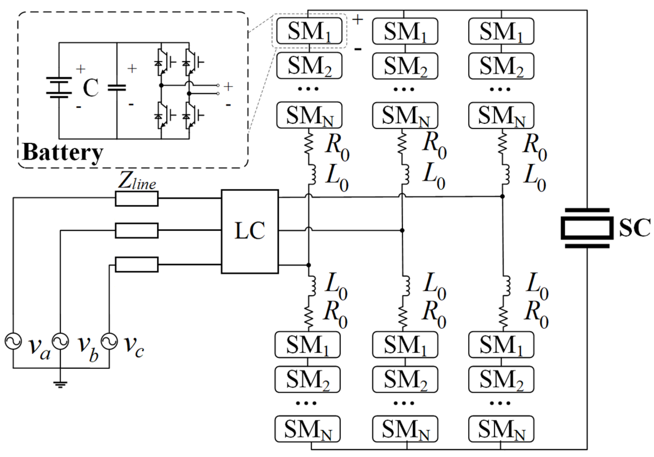
2.1. MMC-HESS Topology

The main circuit topology of MMC-HESS [20] is shown in Figure 1. It features a three-phase bridge arm, each phase consisting of two upper and lower bridge arms, connected by the bridge arm impedance, i.e., the bridge arm inductance L0 and bridge arm resistance R0. Both the upper and lower bridge arms are cascaded with an equal number of identical submodules (SMs), where each submodule is a parallel structure that includes a battery, a full-bridge converter, and a parallel capacitor to control the rate of change of the DC-side voltage during the switching process of the converter bridge. The communication side terminals are drawn from the connection impedance midpoint of each phase’s upper and lower bridge arms and then connected to the grid through an LC filter and line impedance. The necessity of the LC filter depends on the modulation strategy and the number of submodules per arm and is generally not mandatory. The supercapacitor is formed by connecting multiple capacitor cells in series on the DC side.
The modular design of the MMC-HESS bridge arm structures enables direct integration into the 10 kV distribution network without the need for a step-down transformer. Appropriate modulation strategies for the bridge arm voltage can be adopted to reduce the switching frequency requirements of power electronic devices. Compared to two-level converters operating above 2.5 kHz, the MMC-HESS system only requires a switching frequency range of 300–800 Hz, yielding substantial switching loss reductions.
The distributed battery configuration across submodules simplifies individual battery management system (BMS) control while maintaining SM voltage stability under equivalent energy capacity. Supercapacitors are strategically positioned on the full-bridge MMC’s high-voltage DC bus, providing extended voltage regulation range that maximizes SC energy utilization efficiency through adaptive voltage matching.

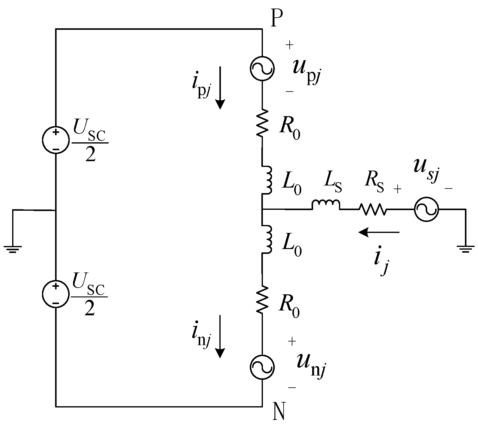
2.2. MMC-HESS Mathematical Model

The single-phase equivalent circuit for three-phase symmetrical operation is illustrated in Figure 2, where usj denotes the AC voltage on the grid side; upj and ipj represent the voltage and current of the upper bridge arm, respectively; unj and inj represent the voltage and current of the lower bridge arm, respectively; USC represents the terminal voltage of the DC-side supercapacitor.
The MMC’s AC and DC sides can be equivalently expressed as:
L e d i j d t + R e i j = u s j e j L 0 d i cir j d t + R 0 i cir j = U SC 2 e dc j
where ej is the AC equivalent electromotive force, edcj is the DC equivalent electromotive force, and icirj is the circulating current. Le and Re are the AC equivalent inductance and resistance, respectively.
The equivalent expression is given by:
e j u n j u p j 2 e dc j u n j + u p j 2 i cir j i n j + i p j 2 L e = L s + L 0 2 R e = R s + R 0 2
By neglecting the high-frequency components of the circulating current icirj and DC electromotive force edcj, and considering only the DC component and the fundamental frequency component [21], the total power absorbed by the single-phase battery PBj and the power difference across the upper and lower bridge arms PΔpnj are expressed as:
P B j = 2 U DC j I DC j + 2 U AC j I AC j cos φ j 3 φ j 1 + U j I j cos φ j 4 φ j 2
P Δ pn j = U AC j I j cos φ j 3 φ j 2 2 U j I AC j cos φ j 4 φ j 1
From Equation (3), the DC component of the circulating current IDCj is introduced into the phase power balance in this topology.
According to Equation (4), the fundamental frequency component of the circulating current IACj is introduced to balance the power between the upper and lower bridge arms [22,23].
Additionally, the nearest-level modulation (NLM) algorithm [24] is used to implement the SOC balancing control between the batteries within the submodules.

2.3. Power Flow Characteristics

The MMC-HESS has four power sources: the grid-side input power Pg, the battery output power Pbat, the supercapacitor output power PSC, and the converter losses PSC. According to the power conservation law, these four powers satisfy:
P b a t + P S C + P g = P S W
Thus, by controlling the AC-side power Pg and the DC-side power PSC, the power distribution and control between the battery and supercapacitor can be achieved. The reference value for the DC-side power PSCref can be distributed by using a filter [25].

3. Hybrid Synchronous Control Strategy

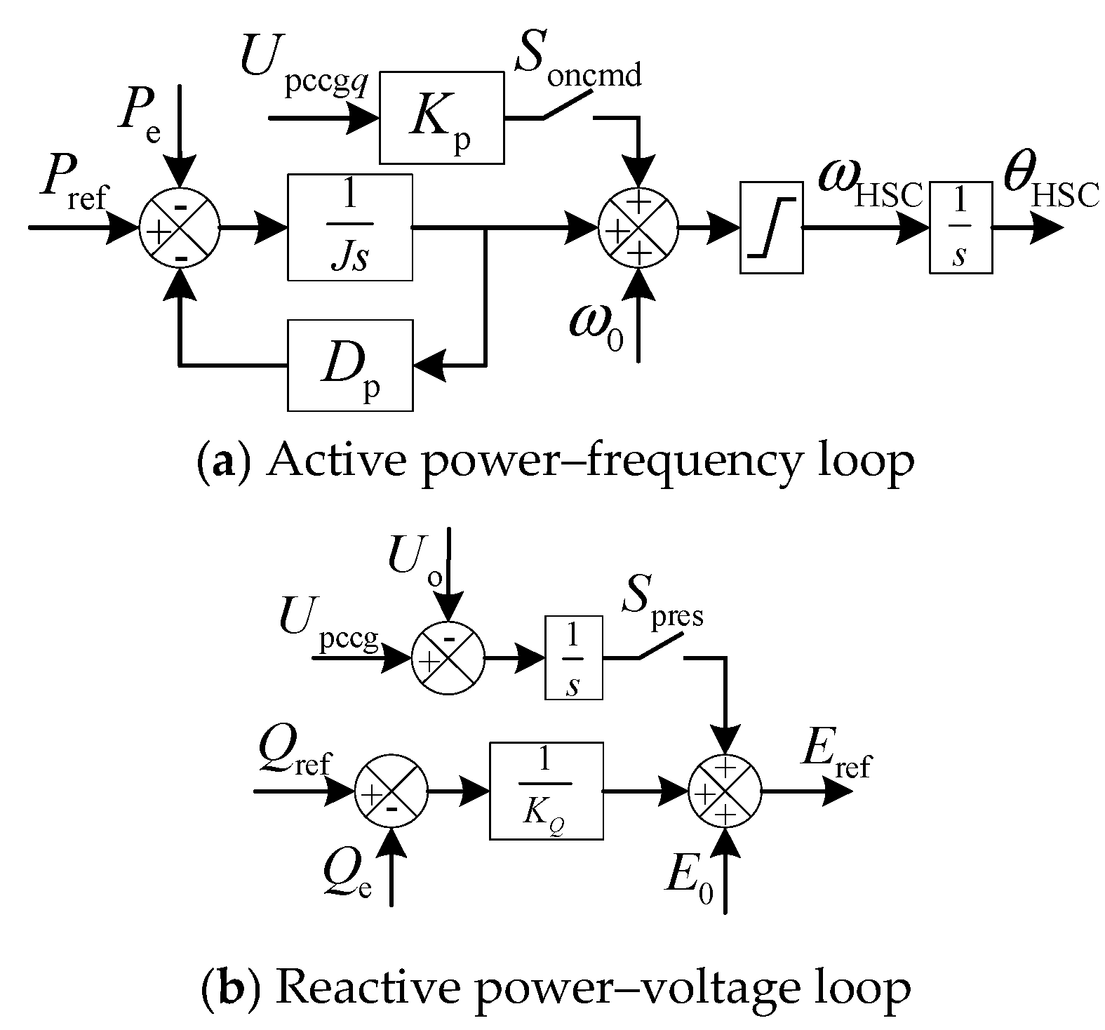
3.1. AC-Side Control Strategy

3.1.1. HSC Power Control Considering Both Grid-Connected and Off-Grid Modes

The HSC power control strategy is based on VSG and PLL control. The frequency control loop incorporates frequency components from both of these control strategies [26].
The VSG active power–frequency control model, which considers virtual inertia, damping characteristics, and primary frequency regulation, is given by the following equation:
P ref P e = J ω 0 d ω d t + D ω 0 + K ω ω ω 0 =      J d ω d t + D p ω ω 0
where J’ is the virtual inertia of the VSG-controlled converter. D’ is the damping factor of the frequency regulator. Kω is the droop coefficient for primary frequency regulation. Pref and Pe are the reference active power and the actual output power, respectively. ω0 is the rated electrical angular frequency (100π rad/s). ω is the actual electrical angular frequency. J and Dp are the inertia and damping coefficients of the simplified oscillation equation.
According to Equation (6), the angular frequency of VSG is:
ω VSG = ω 0 + 1 J s + D p P ref P e
During severe faults, when active power cannot meet the reference value, the oscillation equation will become unstable, and the VSG will lose synchronization with the grid. To solve the synchronization problem, a PLL component is introduced into Equation (7). In practical control, the integral term in PLL causes static errors; so, only the proportional term is kept. This simplifies to:
ω HSC = ω 0 + 1 J s + D p P ref P e + K p U o q
where Uoq is the q-axis component of the output voltage at the grid connection point. Kp is the proportional coefficient of PLL.
Additionally, the MMC islanding mode eliminates PLL components due to absent grid synchronization requirements. During pre-synchronization, analogous phase-locking mechanisms ensure grid–machine voltage alignment through q-axis voltage matching at the converter’s grid terminal. Thus, Uoq is replaced with the q-axis component of the grid-side voltage Upccgq.
The adjusted frequency of HSC is:
ω HSC = ω 0 + P ref P e J s + D p + S oncmd K p U pccg q
where Soncmd represents the grid connection control signal, which is 1 during grid-connected operation and pre-synchronization, and 0 during off-grid operation.
The VSG’s reactive voltage loop usually uses droop control. During pre-synchronization, in addition to achieving phase synchronization (9), voltage amplitude matching is required. The adjusted voltage reference is:
E ref = E 0 + Q ref Q e K Q + S pres U pccg U o s
where KQ is the reactive power–voltage droop coefficient; Eref and E0 are the voltage reference value and the rated value, respectively; Qref and Qe are the reactive power reference value and the actual output value, respectively; Upccg and Uo are the grid-side voltage amplitude and the machine-side voltage amplitude of the grid connection switch, respectively; Spres represents the pre-synchronization signal, where it is 1 during pre-synchronization and 0 at other times.
In summary, the HSC power control loop for both grid-connected and islanding control is shown in Figure 3, including the active power–frequency loop and reactive power–voltage loop.
In Figure 3, the active power–frequency loop generates the VSG frequency component based on the reference active power Pref and actual active power Pe. The PLL frequency component is derived from the q-axis component of the grid-side voltage Upccgq and the grid connection control signal Soncmd. Both frequency components are then combined with the nominal frequency ω0 to form the output frequency ωHSC. After integration, the reference phase angle θHSC is obtained. The reactive power–voltage loop generates the reactive voltage droop component based on the reference reactive power Qref and actual reactive power Qe. It also generates the pre-synchronization component using the grid-side voltage magnitude Upccg, machine-side voltage magnitude Uo, and the pre-synchronization signal Spres. Both voltage components are combined with the rated voltage E0 to form the output voltage reference Eref.

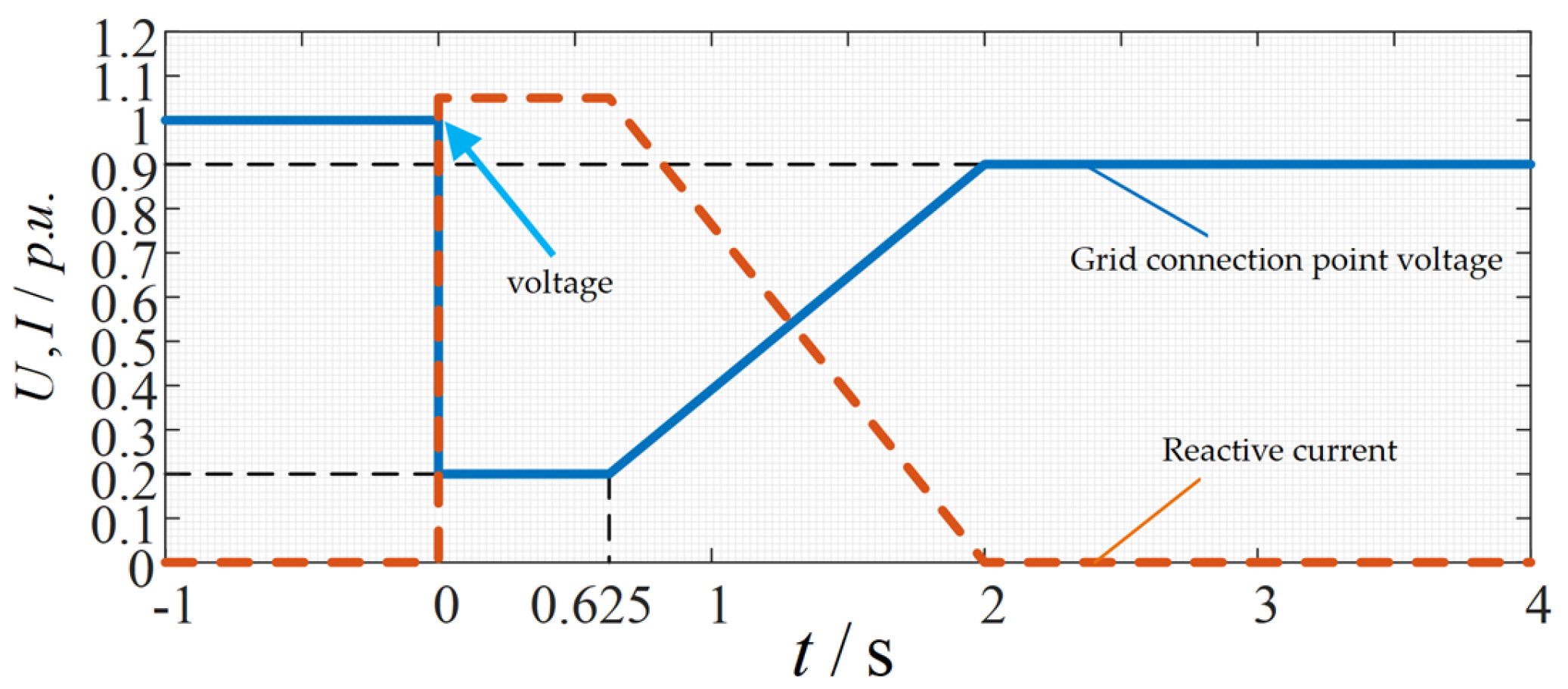
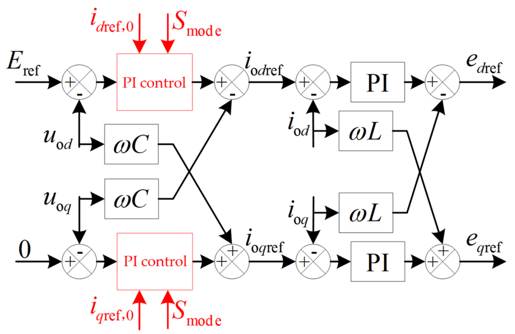
3.1.2. Low-Voltage Ride-Through Switching Strategy

Figure 4 specifies the reactive current compensation thresholds and islanding timing criteria: system operation switches to islanding mode when voltages persist below the defined threshold curve, while maintaining grid connection with reactive current injection above the curve.
According to Equation (10), the HSC reactive voltage loop cannot meet the reactive current curve and has a slow response. Therefore, during voltage sag, the q-axis current reference value output by the q-axis voltage loop should be switched to the reactive current curve shown in Figure 4. However, after switching the iqref, the d-axis voltage loop will no longer track the reference without static error. Therefore, the d-axis current reference value needs to be switched simultaneously; the switched current reference value is:
i q ref , 0 = 1.5 0.9 U pccg , 0.2 U pccg 0.9 1.05 , U pccg < 0.2 i d ref , 0 = min P ref U pccg , 1.2 2 i q ref 2
The fault islanding time is:
t U pccg = , U pccg > 0.9 2 1.375 0.9 U pccg 0.7 , 0.2 U pccg 0.9 0.001 , U pccg < 0.2
After fault recovery or islanding operation, the fault current-limiting mode is exited. To reduce the impact current after switching modes during grid connection, the fault current-limiting mode will continue until ωHSC stabilizes. The voltage loop PI controller will be improved to a compensatable PI controller, as shown in the control block diagram in Figure 5.
In Figure 5, the output value idqref,1 of the PI controller is:
i d q ref , 1 = K p + K i s Δ u , S mode = 1 K p Δ u + K i K p s + K i i d q ref , 0 , S mode = 0
where Smode is the mode switching signal, which is 0 after a voltage sag during grid connection and 1 during islanding operation or normal grid connection. idqref,0 is the current reference during fault current limiting.
The voltage loop employs PI control in grid-connected/islanded modes. During grid-connected voltage sags, current reference transitions to fault-limited output—PI output becomes superposition of fault-limited value and proportional term. When switching from grid-fault to islanded/normal grid operation, the integrator initializes with a fault-limited value, expediting transient recovery.
The dual-loop control block diagram considering low-voltage ride-through is shown in Figure 6.
In the voltage control loop, which includes the PI compensating controller and LC filtering capacitor decoupling term, as shown in Figure 6, the current reference values iodref and ioqref are obtained based on the dq-coordinate voltage reference Eref, 0, and the actual values uod, uoq. In the current control loop, which includes the traditional PI controller and LC filtering inductance decoupling term, the dq-coordinate reference values for the AC equivalent electromotive force edref, eqref are calculated from the current reference values iodref, ioqref and their actual values iod, ioq.

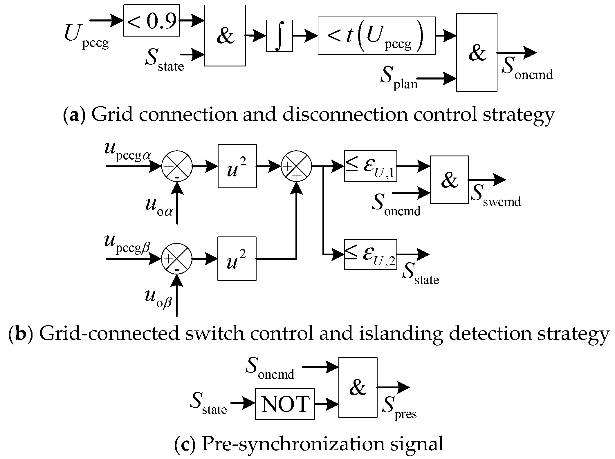
3.1.3. Islanding Detection and Grid Connection/Island Operation Control

The grid connection and island operation control strategies, as well as the islanding detection strategy, are shown in Figure 7. In Figure 7, the following symbols are used: Splan, Soncmd, Sswcmd, Sstate, and Spres represent the grid connection plan (this signal is actively set and should be set to 1 when grid connection is required), grid connection control, grid switch, islanding grid state, and pre-synchronization signal, respectively. Upccg, upccgα, and upccgβ represent the magnitude, α-axis component, and β-axis component of the grid-side voltage of the grid switch. εU,1, εU,2 are the grid switch closing judgment threshold and islanding detection threshold.
As shown in Figure 7a, the system can directly operate in islanding mode during planned disconnection, or it can disconnect and operate in islanding mode under fault conditions where the grid-connected state operates below the voltage curve shown in Figure 6, by setting Soncmd = 0.
As shown in Figure 7b, when Soncmd = 0, the grid switch directly opens. When Soncmd = 1, the grid switch closes based on the squared difference of voltage phasors on both sides of the switch. Islanding and grid connection states are also detected based on the squared difference of the voltage phasors.
As shown in Figure 7c, the pre-synchronization signal introduced into the reactive power–voltage loop is derived from the grid connection control signal Soncmd and the islanding grid state Sstate.

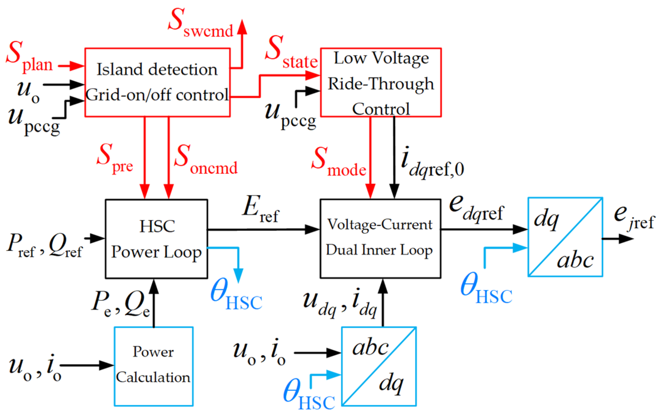
3.1.4. Overall AC-Side Control Model

The AC-side control model, shown in Figure 8, includes the HSC power loop, the voltage–current double inner loop, low-voltage ride-through control, and islanding detection and grid connection/islanding control modules. The AC-side control strategy, based on the grid connection plan Splan, the PCC point grid-side voltage upccg, the machine-side voltage u0, the current i0, and the AC-side power commands Pref and Qref, generates the system’s grid switch control signal Sswcmd and the AC equivalent electromotive force reference values ejref.

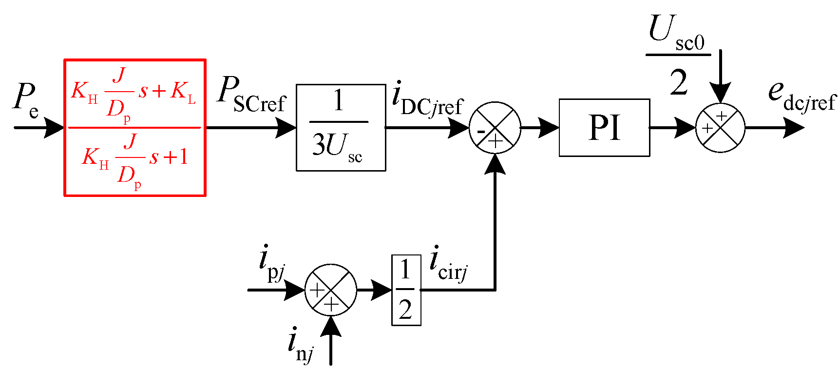
3.2. Supercapacitor Power Distribution Strategy

According to Equation (9), ignoring the response time of the voltage–current double loop, the relationship between the output power and the voltage frequency variation at the grid connection point is given by:
Δ P e = J s + D p Δ ω HSC
To mitigate battery power and slow down aging, the high-frequency components of the power are allocated to the supercapacitor. At the same time, considering the health management of the supercapacitor, the low-frequency response components of the supercapacitor are appropriately increased. Based on Equation (14), the reference value for DC-side SC power is given by:
P SCref = K H J D p s + K L K H J D p s + 1 P e
where KH and KL are the high-frequency and low-frequency compensation coefficients for the supercapacitor, respectively. PSCref is the discharge power reference value.
The voltage state coefficient αSC is used as the coefficient configuration basis, defined as:
α SC = U SC U SC min U SC max U SC min
where USCmax and USCmin are the upper and lower boundaries for the supercapacitor’s operating voltage. α is defined to range from 0.05 to 0.95 for the working interval, with 0.25 to 0.75 being defined as the healthy interval.
Based on the inertia and damping coefficients of the active ring, as well as the battery power suppression time constant TB, the coefficient KH is configured as:
K H = 0 ,   d P e d t < 0 α S C 0.95 0 ,   d P e d t > 0 α S C 0.05 T B D p J ,   e l s e                                                  
For the pre-set supercapacitor ratio KL0, to reduce the supercapacitor’s operation time in non-healthy intervals, the coefficient KL is configured as:
K L = α S C 0.75 0.2 K L 0 ,   P e > 0 α S C > 0.75 0.25 α S C 0.2 K L 0 ,   P e < 0 α S C < 0.25 0 ,   e l s e                                                  
The DC-side SC power control block diagram for the MMC-HESS is shown in Figure 9. Based on the AC-side output power Pe and the supercapacitor compensation coefficients KH and KL, the supercapacitor power reference value PSCref is calculated. This is then divided by the DC voltage USC, and the value is split equally across the three phases to obtain the circulating DC reference value iDCjref. The difference between this and the actual circulating current icirj is processed by a PI controller to derive the DC equivalent electromotive force reference value eDCjref.

3.3. SOC Balancing Strategy

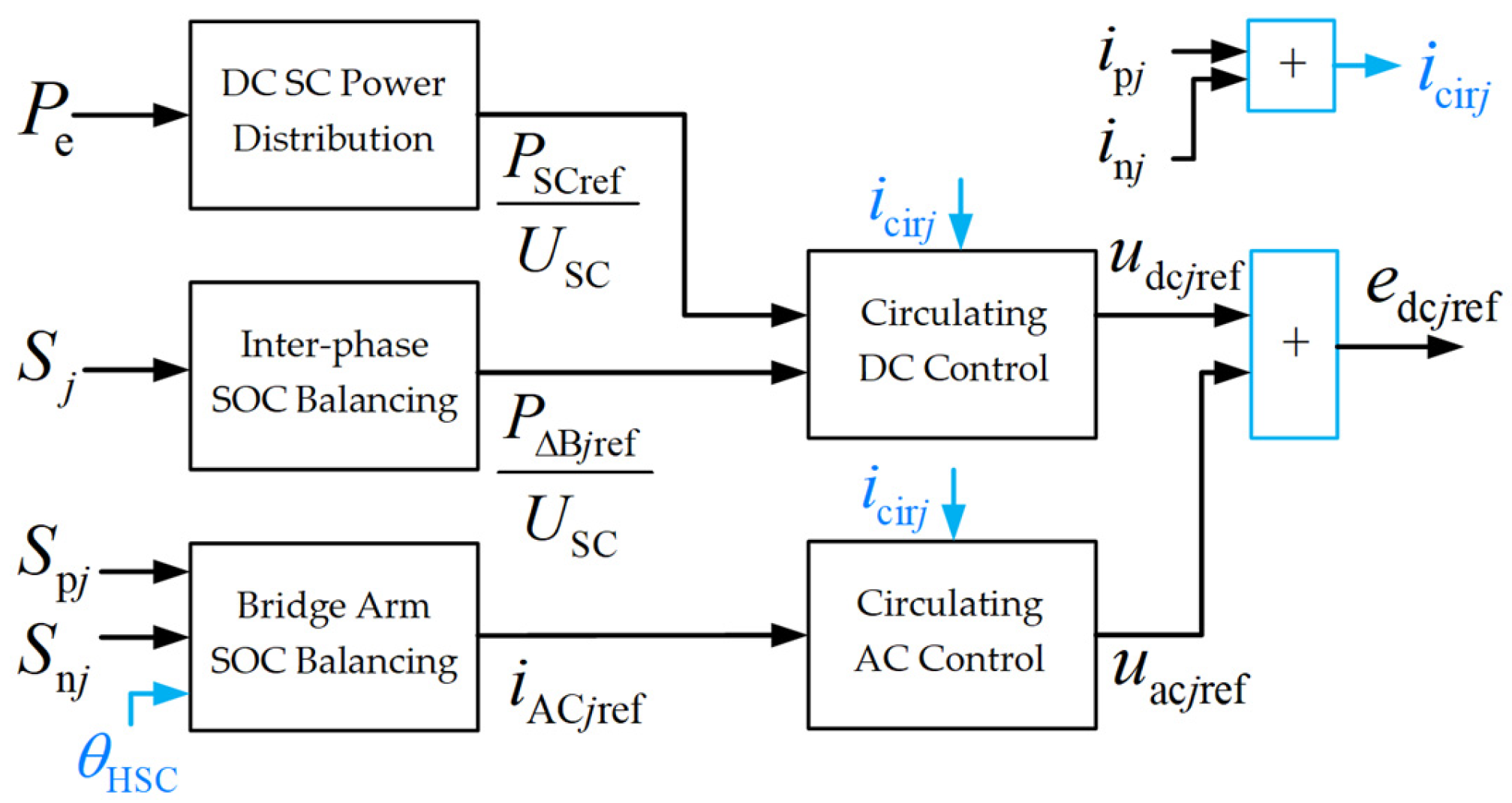
3.3.1. Bridge Arm SOC Balancing and Circulating Current Control

According to Equation (3), a phase-to-phase power correction value is introduced into the circulating DC component iDCjref in the DC-side SC power control to balance the phase-to-phase SOC.
According to Equation (4), an AC fundamental frequency component iACj, in phase with the AC-side voltage, is introduced to balance the SOC between the upper and lower arms of the system. The zero-sequence component of the circulating current introduces a power fundamental frequency component on the DC side. Therefore, after removing the zero-sequence component from the reference value, the fundamental frequency circulating current component is controlled using a resonant PR controller.
Figure 10 illustrates the circulating current control model, which comprises the circulating DC control module and the fundamental frequency control module. The circulating current control strategy determines the system’s circulating current reference value based on the AC output power Pe and the arm currents ipj and inj, as well as the average SOC values Spj and Snj of each arm. Subsequently, the DC equivalent electromotive force reference value eDCjref is derived.

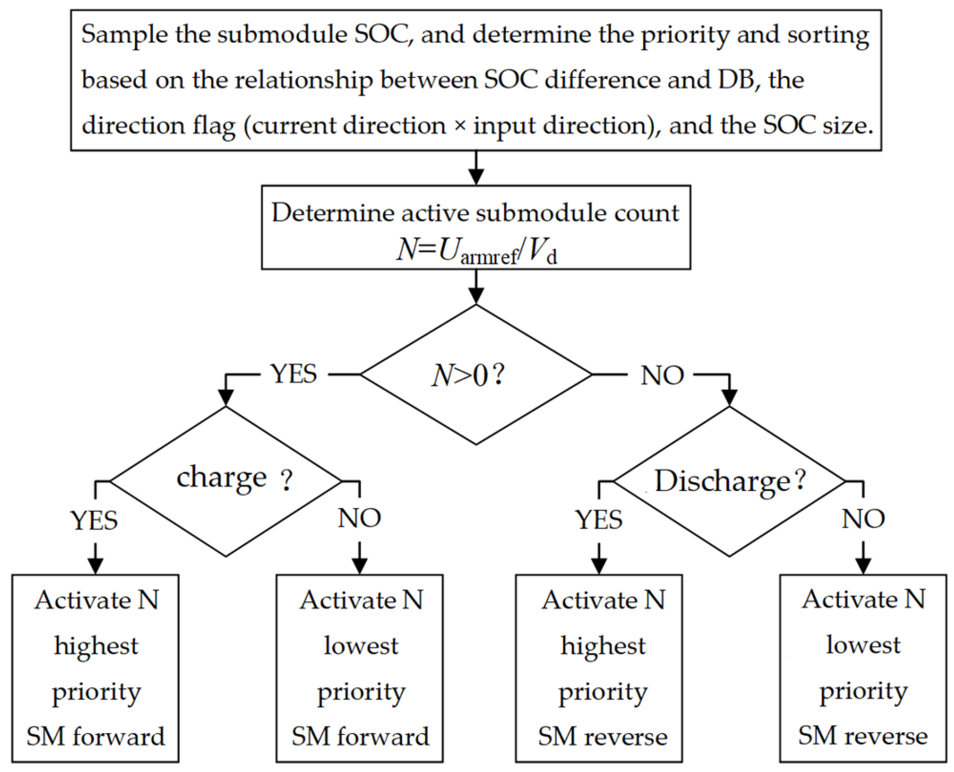
3.3.2. SOC Balancing and Voltage Modulation Within the Bridge Arm

The SOC balancing control within the bridge arm is shown in Figure 11. The number of submodules to be activated N is determined by the ratio of the bridge arm voltage reference Uarmref to the battery’s rated voltage Vd. The deadband (DB) defines the permissible SOC difference between two batteries. When the SOC difference does not exceed the deadband, the batteries are sorted according to their current state. The calculation formula for Uarmref is shown in Equation (19).
U armref = K p , n K p = 1 K n = 1 e j ref + u dc j ref + u ac j ref e dc j ref

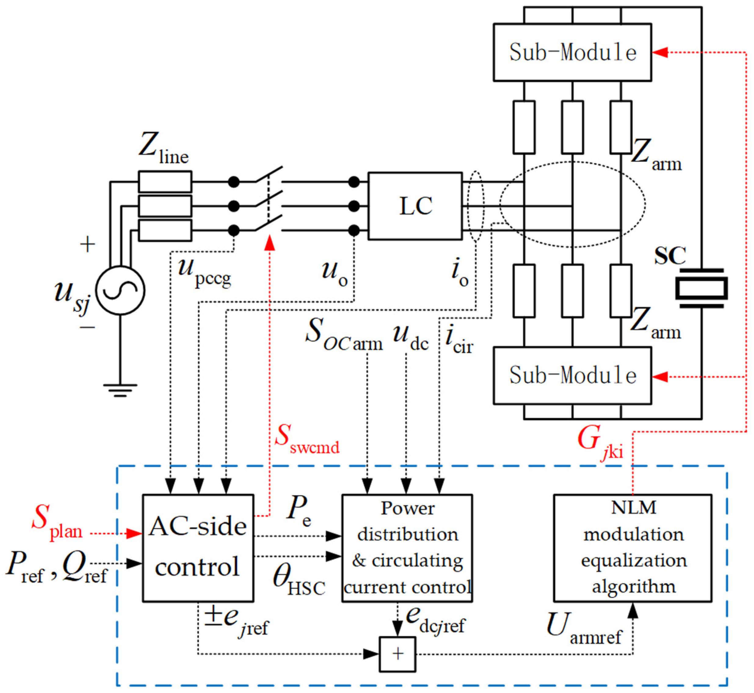
3.4. Overall System Control Model

Figure 12 shows system control architecture with AC/DC power regulation and submodule modulation. AC-side HSC control enables frequency support and grid synchronization during faults/transients, while generating grid-connect/islanding signals. DC-side direct power control manages supercapacitors, coordinating with AC-side strategies to optimize storage dispatch and mitigate battery aging. Submodule control implements SOC balancing for battery stacks, enhancing utilization efficiency.

4. Discussion

To verify the HSC-MMC-HESS topology and control strategy mentioned above, a hardware-in-the-loop experimental model was constructed based on the experimental platform shown in Figure 13; the controller model is Texas Instruments TMS320F28335. The system parameters are listed in Table 2. The voltage and current waveforms observed by the oscilloscope under normal operation are shown in Figure 14.

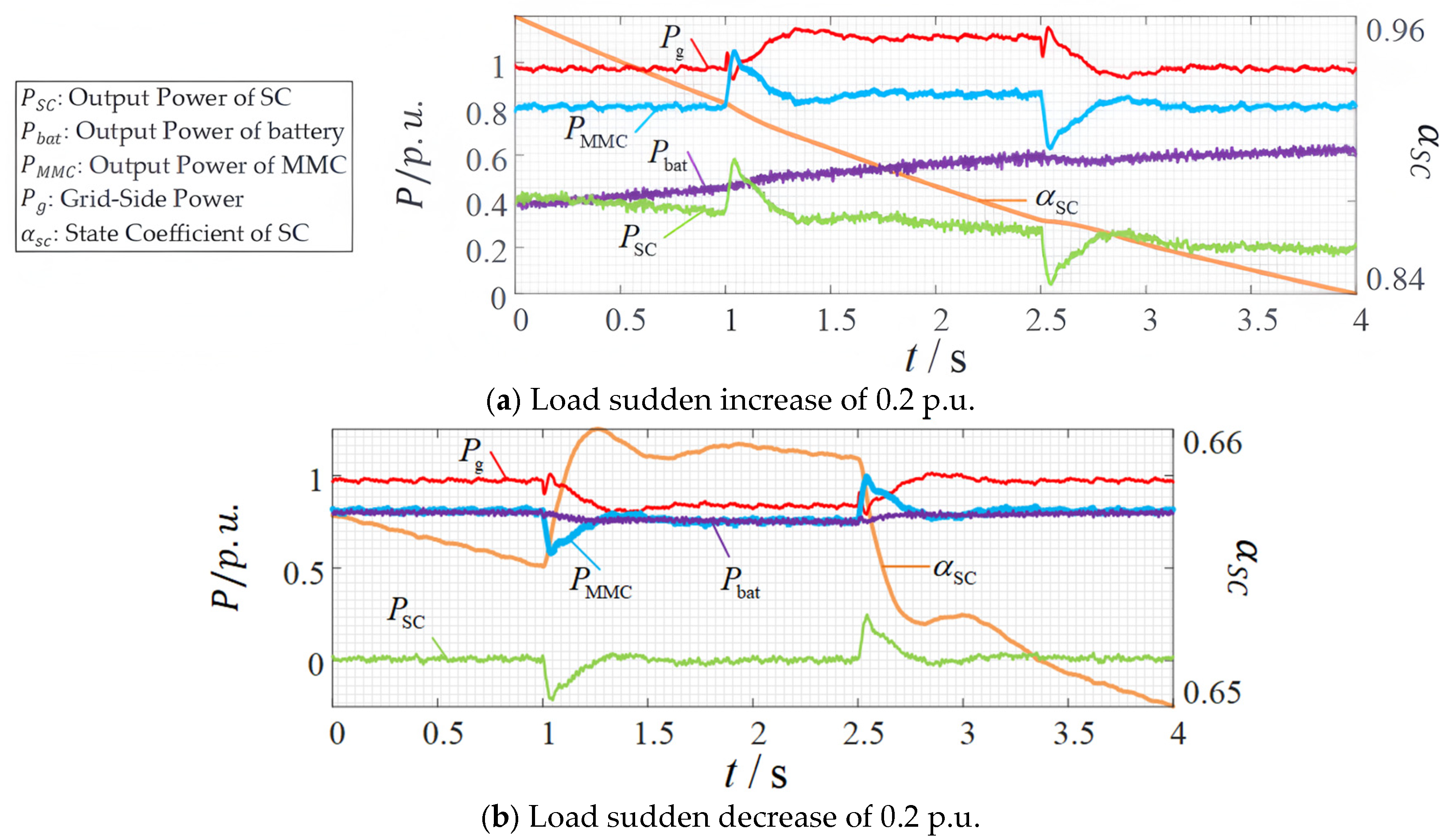
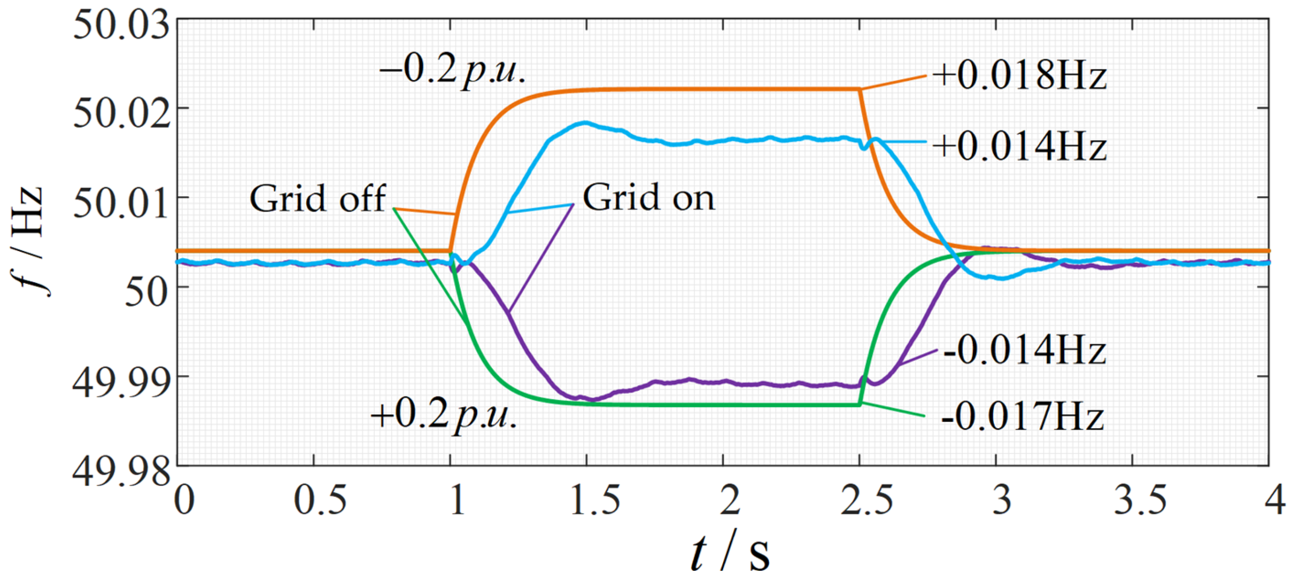
4.1. Inertia, Frequency Support, and Power Distribution

To verify the inertia and frequency support capabilities of the HSC-MMC-HESS and the feasibility of the power distribution strategy between energy storage and supercapacitors, a load step change experiment was conducted on the above-mentioned experimental platform. The grid-side power source simulates a synchronous machine, where J and Dp are 50 and 500, respectively. The initial load of the grid side is 1 p.u., and it steps to 1.2 p.u. and 0.8 p.u., respectively, for 1.5 s before recovery. The MMC machine-side load is 0.8 p.u., and the power command is 0.8 p.u. Under grid-connected conditions, the output power profile during load step changes is depicted in Figure 15, while the corresponding frequency variations are shown in Figure 16. For comparison with the grid-connected scenario, the frequency response under islanded operation during the same load transient is also presented in Figure 16.
From Figure 15, it can be seen that after a load step change on the grid side, the transient change in MMC output power has inertia and damping characteristics, providing or absorbing about 0.016 p.u. of active power to or from the grid. The inertia and frequency support capability are effectively verified. From Figure 16, it can be seen that the frequency variation of the grid-side power source is reduced after connection. When the load increases by 0.2 p.u., due to the supercapacitor voltage state coefficient α > 0.75 and its discharging state, the supercapacitor takes on part of the low-frequency power component. When α > 0.95, the maximum share reaches 0.5, which is the set KL0. The power distribution strategy allows the supercapacitor to effectively handle high-frequency power components and some low-frequency power components while preventing overcharging or over-discharging, stabilizing the battery output power.

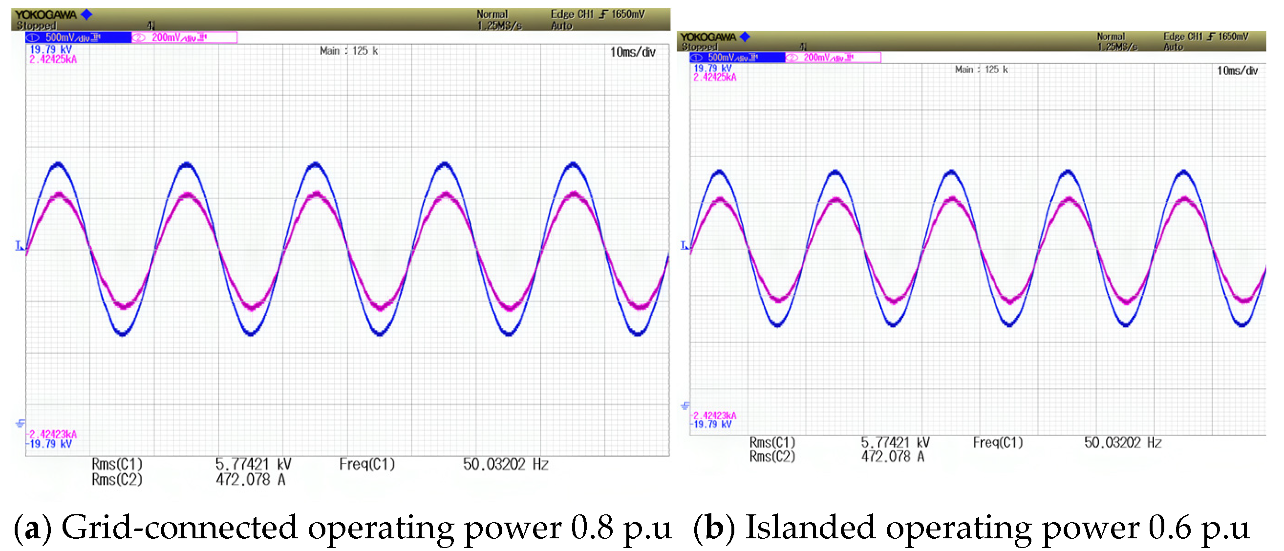
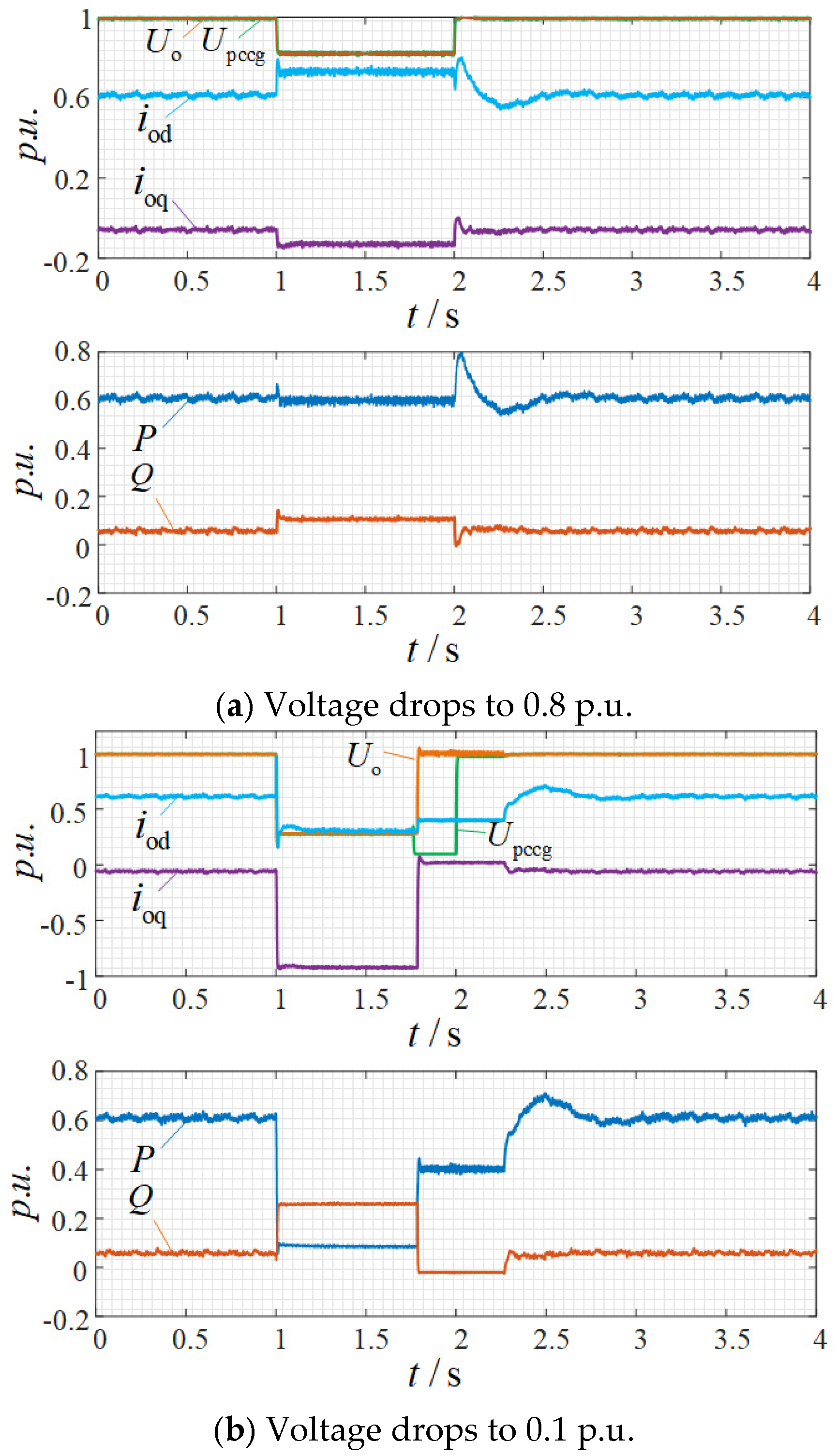
4.2. Low-Voltage Ride-Through and Grid Connection/Disconnection Switching

To verify the low-voltage ride-through switching function of the MMC-HSC and the grid connection and disconnection switching function, a voltage drop experiment was performed on the above-mentioned experimental platform. The grid-side load is 1.2 p.u., the machine-side load is 0.4 p.u., and the MMC active power command is 0.6 p.u. The voltage drops to 0.8 p.u. and 0.1 p.u., respectively, and recovers after 1 s. The output power and voltage curves are shown in Figure 17, and the voltage and current waveform when the grid voltage drops to 0.1 p.u. is shown in Figure 18.
From Figure 17a, when the voltage drops to 0.8 p.u., the system switches to current control, and the current amplitude does not reach the limit of 1.2 p.u.; so, the active power remains at 0.6 p.u. After 1 s, the voltage recovers, and the system exits the current control mode. From Figure 17b, when the voltage drops to 0.1 p.u., the output is reactive current, which compensates the grid voltage to 0.28 p.u. The current amplitude reaches the limit, and the active power is constrained. According to Equation (12), the system operates in islanded mode for about 0.79 s, with an output power of 0.4 p.u. from the machine-side load. After 1 s, the voltage recovers, and the MMC continues to grid connect after pre-synchronization. Based on the results above, the system can automatically and reliably switch between low-voltage ride-through, normal grid connection, and disconnection modes.

4.3. SOC Balancing Control

In the above experiment, the SOC balancing control was operating, and the SOC waveform is shown in Figure 19.
From Figure 19, it can be seen that after limiting the two components of the circulating current, the SOC balancing between phases and between the upper and lower bridge arms is achieved after approximately 23 s and 33 s post-startup, respectively. Through the intra-bridge arm submodule SOC balancing control, the SOC is maintained in a state of basic equilibrium within the deadband range.

5. Conclusions

The proposed HSC-MMC-HESS topology with hybrid synchronous control demonstrates inherent inertia support and frequency regulation capabilities, effectively enhancing grid stability through integrated LVRT functionality that enables reactive voltage support during faults and smooth grid–islanding transitions. By combining SOC-based power allocation with energy storage coordination, the system optimizes supercapacitor–battery synergies to improve utilization rates while mitigating device aging, showing strong potential for medium-voltage distribution network applications.
Future work can address computational complexity from massive submodules in large-grid applications, while renewable integration scenarios require adaptive filtering to mitigate supercapacitor aging caused by power fluctuation-induced frequent cycling.

Author Contributions

Conceptualization, C.Y., J.G., J.Y., B.L. and X.D.; methodology, C.Y. and J.G.; investigation, X.W. and P.S.; writing—review and editing, Y.F. and W.Z.; visualization, J.Y.; supervision, J.G.; project administration, B.L. All authors have read and agreed to the published version of the manuscript.

Funding

This work was supported by the Science and Technology Project of State Grid Corporation of China titled Research on Grid-Forming Energy Storage System Operation Theory, Control Methods and Prototype Development (No.52199723002A).

Data Availability Statement

The original findings and contributions of this study are detailed within the article. For additional information, please contact the corresponding authors.

Conflicts of Interest

Authors Chuan Yuan, Jing Gou, Jiao You, Bo Li and Xinwei Du were employed by the company State Grid Sichuan Electric Power Company. Authors Xi Wang and Peng Shi were employed by the company Electric Power Research Institute, State Grid Sichuan Electric Power Company. The remaining authors declare that the research was conducted in the absence of any commercial or financial relationships that could be construed as a potential conflict of interest.

References

  1. Liu, D.; Yang, Q.; Chen, Y.; Chen, X.; Wen, J. Optimal Parameters and Placement of Hybrid Energy Storage Systems for Frequency Stability Improvement. Prot. Control Mod. Power Syst. 2025, 10, 40–53. [Google Scholar] [CrossRef]
  2. Li, X.; Wang, S. Energy Management and Operational Control Methods for Grid Battery Energy Storage Systems. CSEE J. Power Energy Syst. 2021, 7, 1026–1040. [Google Scholar] [CrossRef]
  3. Xue, S.; Zeng, S.; Song, Y.; Hu, X.; Liang, J.; Qing, H. Adaptive Secondary Frequency Regulation Strategy for Energy Storage Based on Dynamic Primary Frequency Regulation. IEEE Trans. Power Deliv. 2024, 39, 3503–3513. [Google Scholar] [CrossRef]
  4. Cao, J.; Emadi, A. A New Battery/UltraCapacitor Hybrid Energy Storage System for Electric, Hybrid, and Plug-In Hybrid Electric Vehicles. IEEE Trans. Power Electron. 2012, 27, 122–132. [Google Scholar] [CrossRef]
  5. Hredzak, B.; Agelidis, V.G.; Jang, M. A Model Predictive Control System for a Hybrid Battery-Ultracapacitor Power Source. IEEE Trans. Power Electron. 2014, 29, 1469–1479. [Google Scholar] [CrossRef]
  6. Lukic, S.M.; Cao, J.; Bansal, R.C.; Rodriguez, F.; Emadi, A. Energy Storage Systems for Automotive Applications. IEEE Trans. Ind. Electron. 2008, 55, 2258–2267. [Google Scholar] [CrossRef]
  7. Xu, Y.; Zhang, Z.; Wang, G.; Xu, Z. Modular Multilevel Converter with Embedded Energy Storage for Bidirectional Fault Isolation. IEEE Trans. Power Deliv. 2022, 37, 105–115. [Google Scholar] [CrossRef]
  8. Qiu, S.; Shi, B. An Enhanced Battery Interface of MMC-BESS. In Proceedings of the 2019 IEEE 10th International Symposium on Power Electronics for Distributed Generation Systems (PEDG), Xi’an, China, 3–6 June 2019. [Google Scholar] [CrossRef]
  9. Zeng, W.; Li, R.; Huang, L.; Liu, C.; Cai, X. Approach to Inertial Compensation of HVdc Offshore Wind Farms by MMC With Ultracapacitor Energy Storage Integration. IEEE Trans. Ind. Electron. 2022, 69, 12988–12998. [Google Scholar] [CrossRef]
  10. Yu, X.; Wang, C.; Wang, Y.; Han, C. Arm Average Model and Operational Characteristics Analysis of MMC with Integrated Battery Energy Storage System. In Proceedings of the 2023 IEEE 2nd International Power Electronics and Application Symposium (PEAS), Guangzhou, China, 10–13 November 2023; pp. 1426–1431. [Google Scholar] [CrossRef]
  11. Feng, G.; Ye, Y.; Sharma, R. A Modular Multilevel Converter Based Battery-Ultracapacitor Hybrid Energy Storage System for Photovoltaic Applications. In Proceedings of the 2015 Clemson University Power Systems Conference (PSC), Clemson, SC, USA, 10–13 March 2015. [Google Scholar] [CrossRef]
  12. Zhang, L.; Tang, Y.; Yang, S.; Gao, F. A Modular Multilevel Converter-Based Grid-Tied Battery-Supercapacitor Hybrid Energy Storage System with Decoupled Power Control. In Proceedings of the 2016 IEEE 8th International Power Electronics and Motion Control Conference (IPEMC-ECCE Asia), Hefei, China, 22–26 May 2016. [Google Scholar] [CrossRef]
  13. Liu, J.; Miura, Y.; Bevrani, H.; Ise, T. Enhanced Virtual Synchronous Generator Control for Parallel Inverters in Microgrids. IEEE Trans. Smart Grid 2017, 8, 2268–2277. [Google Scholar] [CrossRef]
  14. Li, J.; Wen, B.; Wang, H. Adaptive Virtual Inertia Control Strategy of VSG for Micro-Grid Based on Improved Bang-Bang Control Strategy. IEEE Access 2019, 7, 39509–39514. [Google Scholar] [CrossRef]
  15. Ban, G.; Xu, Y.; Zhang, G.; Wu, Z.; Ma, X.; Yuan, X. Research on VSG Control Strategy for Improving Damping Performance of Weak Grid. In Proceedings of the 2021 IEEE Sustainable Power and Energy Conference (iSPEC), Nanjing, China, 23–25 December 2021; pp. 1766–1771. [Google Scholar] [CrossRef]
  16. Yang, R.; Shi, G.; Zhang, C.; Li, G.; Cai, X. Internal Energy Based Grid-Forming Control for MMC-HVDC Systems with Wind Farm Integration. IEEE Trans. Ind. Appl. 2023, 59, 503–512. [Google Scholar] [CrossRef]
  17. Ji, K.; Pang, H.; Liu, S.; Tang, G. Impedance Analysis Considering Unstable Subsystem Poles for MMC-HVDC-Based Wind Farm Integration System. CSEE J. Power Energy Syst. 2022, 8, 634–639. [Google Scholar]
  18. Saeedifard, M.; Iravani, R. Dynamic Performance of a Modular Multilevel Back-to-Back HVDC System. IEEE Trans. Power Deliv. 2010, 25, 2903–2912. [Google Scholar] [CrossRef]
  19. Wang, Z.; Zhang, J.; Huang, X.; Deng, F. Control Strategy of Grid Forming MMC System for Grid Voltage Sag Ride Through. In Proceedings of the 2024 IEEE 10th International Power Electronics and Motion Control Conference (IPEMC2024-ECCE Asia), Chengdu, China, 17–20 May 2024; pp. 1133–1138. [Google Scholar] [CrossRef]
  20. Cai, W.; Hu, P.; Jiang, D.; Liang, Y. An MMC Based Hybrid Energy Storage System: Concept, Topology, and Control. In Proceedings of the 2020 IEEE 3rd Student Conference on Electrical Machines and Systems (SCEMS), Jinan, China, 4–6 December 2020; pp. 680–685. [Google Scholar] [CrossRef]
  21. Hu, P.; Teodorescu, R.; Guerrero, J.M. Negative-Sequence Second-Order Circulating Current Injection for Hybrid MMC Under Over-Modulation Conditions. IEEE J. Emerg. Sel. Top. Power Electron. 2020, 8, 2508–2519. [Google Scholar] [CrossRef]
  22. Zhang, L.; Gao, F.; Li, N. Control Strategy of MMC Battery Energy Storage System Under Asymmetrical Grid Voltage Condition. Chin. J. Electr. Eng. 2016, 2, 76–83. [Google Scholar] [CrossRef]
  23. Barresi, M.; De Simone, D.; Piegari, L. Direct State-of-Charge Balancing Control for Modular Multilevel Converter Integrating Batteries. IEEE J. Emerg. Sel. Top. Power Electron. 2025, 13, 733–746. [Google Scholar] [CrossRef]
  24. Hu, P.; Teodorescu, R.; Wang, S.; Li, S.; Guerrero, J.M. A Currentless Sorting and Selection-Based Capacitor-Voltage-Balancing Method for Modular Multilevel Converters. IEEE Trans. Power Electron. 2019, 34, 1022–1025. [Google Scholar] [CrossRef]
  25. Izadi, Y.; Beiranvand, R. A Comprehensive Review of Battery and Supercapacitor Cells Voltage-Equalizer Circuits. IEEE Trans. Power Electron. 2023, 38, 15671–15692. [Google Scholar] [CrossRef]
  26. Liu, T.; Wang, X. Physical Insight into Hybrid-Synchronization-Controlled Grid-Forming Inverters Under Large Disturbances. IEEE Trans. Power Electron. 2022, 37, 11475–11480. [Google Scholar] [CrossRef]
Figure 1. The topology of MMC-HESS.
Processes 13 01580 g001
Figure 2. Single-phase equivalent circuit.
Processes 13 01580 g002
Figure 3. The block diagram of HSC power control.
Processes 13 01580 g003
Figure 4. Low-voltage ride-through and escape line.
Processes 13 01580 g004
Figure 5. The block diagram of voltage loop.
Processes 13 01580 g005
Figure 6. The block diagram of voltage and current double loop.
Processes 13 01580 g006
Figure 7. Connection strategy and isolation detection.
Processes 13 01580 g007
Figure 8. AC control strategy block diagram.
Processes 13 01580 g008
Figure 9. The control block diagram of DC power control.
Processes 13 01580 g009
Figure 10. Circulating current control block diagram.
Processes 13 01580 g010
Figure 11. SOC balancing control in single arm.
Processes 13 01580 g011
Figure 12. Overall control strategy block diagram.
Processes 13 01580 g012
Figure 13. Hardware-in-the-loop experimentation platform.
Processes 13 01580 g013
Figure 14. Voltage and current curve of A phase.
Processes 13 01580 g014
Figure 15. Power curve.
Processes 13 01580 g015
Figure 16. Output frequency curve.
Processes 13 01580 g016
Figure 17. Voltage and power curves during voltage source dropping.
Processes 13 01580 g017
Figure 18. Voltage and current curve of A phase during voltage source dropping to 0.1 p.u.
Processes 13 01580 g018
Figure 19. SOC curve of (a) bridge arm; (b) submodule in B phase lower arm.
Processes 13 01580 g019
Table 1. Performance comparison of different topologies.
Evaluation MetricTopology 1Topology 2Topology 3
Energy UtilizationHighLowHigh
Dynamic Response TimeSlowMediumFast
Power Distribution EfficiencyLowMediumHigh
SOC Balancing ComplexityHighLowLow
Table 2. HSC-controlled MMC-HESS Parameters.
StructureParameterLabelConfiguration
GridVoltage level/kVVbase10
Rated frequency/Hzf050
Rated capacity/(MV·A)Sbase10
Line inductance (p.u.)Ls0.2
Line resistance (p.u.)Rs0.002
LC filterSeries inductance (p.u.)Lf0.2
Inductive parasitic
resistance (p.u.)
Rf0.02
Parallel capacitance (p.u.)Cf0.02
Parallel parasitic
resistance (p.u.)
RCf0.1
Bridge arm structureSubmodules per bridge armN8
Bridge arm inductance/mHL012
Bridge arm resistance/ΩR00.1
SM internal capacitance/mFC08.4
BatteryRated voltage/kVVBr2.5
Rated capacity/(A·h)QBr20
SOC Initial value/%A phaseupperSOCpa45
lowerSOCna47
B phaseupperSOCpb51
lowerSOCnb49
C phaseupperSOCpc53
lowerSOCnc55
DC-side supercapacitorTotal series capacitance/FCSC1
Upper working voltage
limit/kV
USCmax11
Lower working voltage
limit/kV
USCmin1
HSC
power loop
Virtual inertia (p.u.)J2.5
Damping coefficient (p.u.)Dp100
PLL component ratio coefficient (p.u.)Kp10
Voltage
inner loop
Proportional coefficient (p.u.)Kpv0.5
Integral coefficient (p.u.)Kiv500
Current
inner loop
Proportional coefficient (p.u.)Kpi1
Integral coefficient (p.u.)Kii200
SC powerHigh-frequency component compensation coefficient (p.u.)KH5
Low-frequency component compensation coefficient (p.u.)KL00.5
DC current loopProportional coefficient (p.u.)KpDC0.5
Integral coefficient (p.u.)KiDC100
SOC balanceInter-phase SOC balancing coefficient (p.u.)Kph50
Bridge arm SOC balancing coefficient (p.u.)Karm40
DC component limit of circulating current (p.u.)IDCcir_lim3
AC component limit of circulating current (p.u.)IACcir_lim2
SOC dead zone/%DB0.1
Disclaimer/Publisher’s Note: The statements, opinions and data contained in all publications are solely those of the individual author(s) and contributor(s) and not of MDPI and/or the editor(s). MDPI and/or the editor(s) disclaim responsibility for any injury to people or property resulting from any ideas, methods, instructions or products referred to in the content.

