Article

Innovative Stress Release Stimulation Through Sequential Cavity Completion for CBM Reservoir Enhancement

1
School of Petroleum Engineering, China University of Petroleum (Beijing), Beijing 102249, China
2
Petro China Coalbed Methane Co., Ltd., Beijing 100020, China
3
China United Coalbed Methane National Engineering Research Center Co., Ltd., Beijing 100095, China
4
National Engineering Research Center for Oil & Gas Drilling and Completion Technology, School of Petroleum Engineering, Yangtze University, Wuhan 430100, China
*
Author to whom correspondence should be addressed.
Processes 2025, 13(5), 1567; https://doi.org/10.3390/pr13051567
Submission received: 21 April 2025 / Revised: 13 May 2025 / Accepted: 15 May 2025 / Published: 19 May 2025
(This article belongs to the Special Issue Coalbed Methane Development Process)

Abstract

:
China holds substantial coalbed methane resources, yet low single-well productivity persists. While horizontal well cavity completion offers a permeability-enhancing solution through stress release, its effectiveness remains limited by the incomplete knowledge of stress redistribution and permeability evolution during stress release. To bridge this gap, a fully coupled hydromechanical 3D discrete element model (FLC3D) was developed to investigate stress redistribution and permeability evolution in deep coalbed methane reservoirs under varying cavity spacings and fluid pressures, and a novel sequential cavity completion technique integrated with hydraulic fracturing was proposed to amplify stress release zones and mitigate stress concentration effects. Key findings reveal that cavity-induced stress release zones predominantly develop proximal to the working face, exhibiting radial attenuation with increasing distance. Vertical stress concentrations at cavity termini reach peak intensities of 2.54 times initial stress levels, forming localized permeability barriers with 50–70% reduction. Stress release zones demonstrate permeability enhancement directly proportional to stress reduction magnitude, achieving a maximum permeability of 5.8 mD (483% increase from baseline). Prolonged drainage operations reduce stress release zone volumes by 17% while expanding stress concentration zones by 31%. The developed sequential cavity hydraulic fracturing technology demonstrates, through simulation, that strategically induced hydraulic fractures elevate fluid pressures in stress-concentrated regions, effectively neutralizing compressive stresses and restoring reservoir permeability. These findings provide actionable insights for optimizing stress release stimulation strategies in deep coalbed methane reservoirs, offering a viable pathway toward sustainable and efficient resource development.

1. Introduction

China hosts vast coalbed methane (CBM) resources, yet long-standing challenges in improving single-well productivity persist [1,2,3]. While hydraulic fracturing remains the primary stimulation technique, its efficacy is limited in reservoirs with low elastic modulus, high Poisson’s ratio, and fragile coal structures, where fractures are confined to the near-wellbore region with minimal transformation scope [4,5,6,7]. These constraints underscore the current bottleneck in CBM development, necessitating innovative approaches to enhance reservoir stimulation and production.
Stress release in coal mine goaf areas fundamentally alters reservoir architecture through multi-layered geological restructuring, enabling enhanced CBM recovery [8,9]. Mining-induced deformation generates interconnected fracture networks within upper strata through roof collapse and strata movement, simultaneously creating pressure release arches and surface subsidence patterns while establishing persistent gas migration pathways [10,11,12]. Concurrently, this confines pressure reduction trigger volumetric expansion in lower coal seams, producing irreversible permeability-enhancing fractures that sustain gas flow [13,14,15,16]. The stratigraphic discontinuities formed between disturbed rock layers develop into preferential gas accumulation zones, with interlayer fractures serving as efficient transport channels that persist beyond mining operations [17,18,19]. This cascading structural modification—spanning from macroscopic strata movement to microscopic fracture propagation—establishes an enduring permeability framework critical for CBM exploitation, where stress release fractures function synergistically as both methane reservoirs and migration conduits [20,21,22].
Stress release has emerged as a critical technical strategy for enhancing coalbed methane productivity, with its operational feasibility and geomechanical reliability theoretically validated [23,24,25]. This has spurred extensive research on coal stress release mechanisms, yielding foundational frameworks including key strata theory, “O”-ring theory, overburden “three-zone” partitioning, cantilever beam mechanics, and pressure arch dynamics [26,27,28,29]. However, the deep CBM systems operate under elevated geomechanical complexity characterized by high in situ stresses, non-linear rock deformation, and cavitation-induced stress perturbations that generate the heterogeneous evolution of permeability [30,31,32,33]. These models predominantly address stress redistribution in shallow protective layer mining and associated methane drainage, inadequately capturing the dynamic permeability evolution in deep CBM reservoirs. The direct application of shallow protective layer extraction models fails to resolve the multi-scale stress coupling effects during deep in situ stress release via drilling-induced cavity formation [34,35,36,37]. The absence of robust theoretical frameworks compromises the effectiveness of cavity-completion-based stress release stimulation in vertical CBM wells [38,39], where constrained energy propagation distances prevent the development of periodic tensile–shear stress fields in distal cavern strata, ultimately yielding suboptimal reservoir reconstruction outcomes [23,40]. To overcome the existing limitations, this study aims to advance the theoretical framework of stress relief mechanisms in deep coalbed methane (CBM) reservoirs while developing optimized engineering protocols through three principal approaches: (1) deepen the theory of stress release in deep coalbed methane, (2) amplify stress redistribution radii, and (3) mitigate stress shadowing effects in deep CBM systems.
To address the geomechanical challenges in deep coalbed methane (CBM) development, a coupled hydromechanical model to address deep coalbed methane (CBM) extraction challenges was developed. Integrating dual-porosity/permeability interactions to analyze stress–permeability evolution during cavity-driven stress release, a 3D numerical model of the Daning-Jixian reservoir was constructed by FLAC3D v.5.01. Simulations reveal multiscale stress–permeability coupling mechanisms governed by fracture network bifurcation and shear dilation effects. Building on these insights, an engineered stimulation protocol to simultaneously amplify stress release zones through controlled fracture propagation while mitigating stress concentration effects via targeted energy injection was proposed. The results provide critical insights into deep CBM reservoir dynamics and a practical framework for enhancing recovery via stress field regulation.

2. Methods

2.1. Caving Disturbance–Stress Distribution Model

Due to the influence of mining operations, the original stress balance of the goaf floor will be altered, causing compression, tension, and shear damage to the rock of the floor. Thus, to accurately locate the approximate range of its damage after the change in stress state and in the case of deformation damage, the first thing needed is to determine the stress coordinates of its concentrated load.
To analyze the stresses at certain points of the floor strata in the mining area, it is assumed according to the elastic theory that the coal is a homogeneous elastomer and the stresses at any point of the concentrated load p on the semi-infinite plane body can be used in polar coordinates and right angles.
The coordinate system is expressed as follows [19].
σ x = 2 p y x 2 π x 2 + y 2 2 ; σ y = 2 p y 3 π x 2 + y 2 2 ; τ x y = 2 p y 2 x π x 2 + y 2 2
The polar coordinate formula is as follows.
σ x = 2 p sin 2 θ cos θ π r ; σ y = 2 p cos 3 θ π r ; τ x y = 2 p sin θ cos 2 θ π r
From this, the load expression formula can be deduced to the free boundary through the superposition principle, and the stress calculation formula of any point in the reservoir can be obtained [25]:
σ x = q π arctg x + L 2 y arctg x L 2 y y x + L 2 y 2 + x + L 2 2 + y x L 2 y 2 + x L 2 2
σ y = q π arctg x + L 2 y arctg x L 2 y + y x + L 2 y 2 + x + L 2 2 y x L 2 y 2 + x L 2 2
τ x y = q π y 2 y 2 + x + L 2 2 y 2 y 2 + x L 2 2
where q is the mean load acting directly on the rock and L is the width of the cave.

2.2. Response Model of Pore Permeability Under Stress Release Effect

2.2.1. Model of Pore Permeability Under Stress Release

The increase in effective stress in the reservoir will compress the coal matrix and fractures. After the stress is released, the coal matrix and pore fractures will also recover accordingly. As mentioned earlier, the compression of pore fractures by effective stress directly affects the permeability of coal. At the instant of stress change, the permeability and effective stress satisfy an exponential relationship:
k 1 = a × e b σ e
where k1 is the permeability, both a and b are fitting coefficients, and σe is the effective stress, which refers to the difference between the total stress on the coal and the internal pore pressure.
The subsequent coal gas transport process also affects the pore and fissure structure and permeability of the coal body. According to the coal body structure model, the coal body includes two parts: coal skeleton and fissure. Therefore, during the process of gas transport, the coal volume strain is equal to both the fissure volume strain and the coal skeleton volume strain:
V c = V m + V f Δ V c = Δ V m + Δ V f
where Vc, Vm, and Vf are the coal volume, coal skeleton volume, and fracture volume, respectively; Vm and ΔVf are the volume strain, coal skeleton strain, and fracture strain of the coal body under stress, respectively.
According to the definition of porosity, the porosity of coal after the stress action can be expressed as follows [41].
ϕ f = V f V c = V f 0 + Δ V f V c + Δ V c = 1 V m 0 + Δ V m V c + Δ V c
Equation (8) is simplified to obtain the following:
ϕ f = 1 1 ϕ f 0 1 + ε V 1 + Δ V V m 0
where Vm0 is the initial volume of the coal skeleton, which is the original volume before the effective stress is applied; Vf0 is the initial volume of the fracture, which is the initial volume of the fracture before the effective stress is applied. The sum of them is equal to the total pore volume of coal before the effective stress is applied.
From the above equation, the change in coal porosity under the effective stress depends on the deformation of the coal skeleton.
The deformation of the coal skeleton consists of two components, the action of gas pressure changes in the coal on the coal skeleton and the adsorption and expansion deformation of the coal matrix. Also known as the Langmuir volume strain equation, the above equation can be written as follows:
ϕ f = 1 1 ϕ f 0 1 + ε V 1 + 1 K m ϕ f 0 β f p f p f 0 + β m p m p m 0 Fluid   pressure   deformation   + ε L ϕ f 0 K K m 1 p m p m 0 p m + P L Absorption   expansion   deformation
where βf and βm are the effective stress coefficients of cracks and matrix pores, respectively; K is the bulk modulus of coal; Km is the bulk modulus of the coal matrix; εv and εL are the volumetric strain and matrix strain of coal rock, respectively; PL is Langmuir pressure; pf0 is the initial fracture porosity; pm is the porosity of coal; pf is the fracture porosity of coal.
Since the change in volume strain of the coal during gas transport is small, it can be neglected. The relationship between permeability and porosity can be defined by the cubic equation; the permeability of the coal during gas transport after stress change can be expressed as follows:
k = k 0 × e 3 C f σ i j σ 0 η 1 + γ γ ξ × k 0 e 3 C f σ i j σ 0 η 0 σ v σ b σ b σ v σ d
where η is the coefficient of permeability change due to fluid transport; Cf is the compression coefficient of the crack; γ is the equivalent plastic strain; γ is the equivalent plastic deformation amount when the coal reaches the maximum yield deformation; ξ is the coefficient of permeability increase; σ0 is the original stress of the coal seam; σb is the critical stress for elastic strain and ductile deformation; and σd is the value of the coal fracture stress.
η = 1 + 1 K m ϕ f 0 β f p f p f 0 + β m p m p m 0 Fluid   pressure   deformation + ε L ϕ f 0 K K m 1 p m p m 0 p m + P L Absorption   expansion   deformation 3
The previous discrete models for coalbed stress release predominantly address stress redistribution in shallow protective layer mining and associated methane drainage. However, the deep CBM systems operate under elevated geomechanical complexity characterized by high in situ stresses, non-linear rock deformation, and cavitation-induced stress perturbations that generate the heterogeneous evolution of permeability. Thus, the previous models cannot adequately capture the dynamic permeability evolution during stress release in deep CBM reservoirs. This study proposes a novel stress–seepage coupling framework for high-stress environments, incorporating elastoplastic transitions, fluid pressure dynamics, and diffusion/adsorption–rock deformation interactions. It resolves coupled hydromechanical challenges during deep-drilling-induced stress redistribution, overcoming limitations in phase transition representation and rock–fluid coupling. The model advances theoretical insights into stress release–seepage synergies while enabling predictive simulations of fracture networks and fluid migration for enhanced stress release stimulation technologies.

2.2.2. Boundary Conditions of the Model

Based on the actual stress state of coal seams and surrounding rocks, the boundary and initial conditions for the coal seam deformation are defined following Liu et al. (2015) [42].
The displacement and stress conditions at the boundaries are as follows:
u i = u i ( t ) o n Ω
σ i j n = f i ( t ) o n Ω
where ui(t) and fi(t) denote the known displacement and stress components at the boundary, respectively, while n represents the directional vector along the boundary.
Initial displacement and stress conditions in the solved region were as follows:
u i ( 0 ) = u 0 i n Ω
σ i j ( 0 ) = σ 0 i n Ω
where u0 and σ0 are initial values of displacement and stress in the domain, respectively.

2.3. Construction of Numerical Models

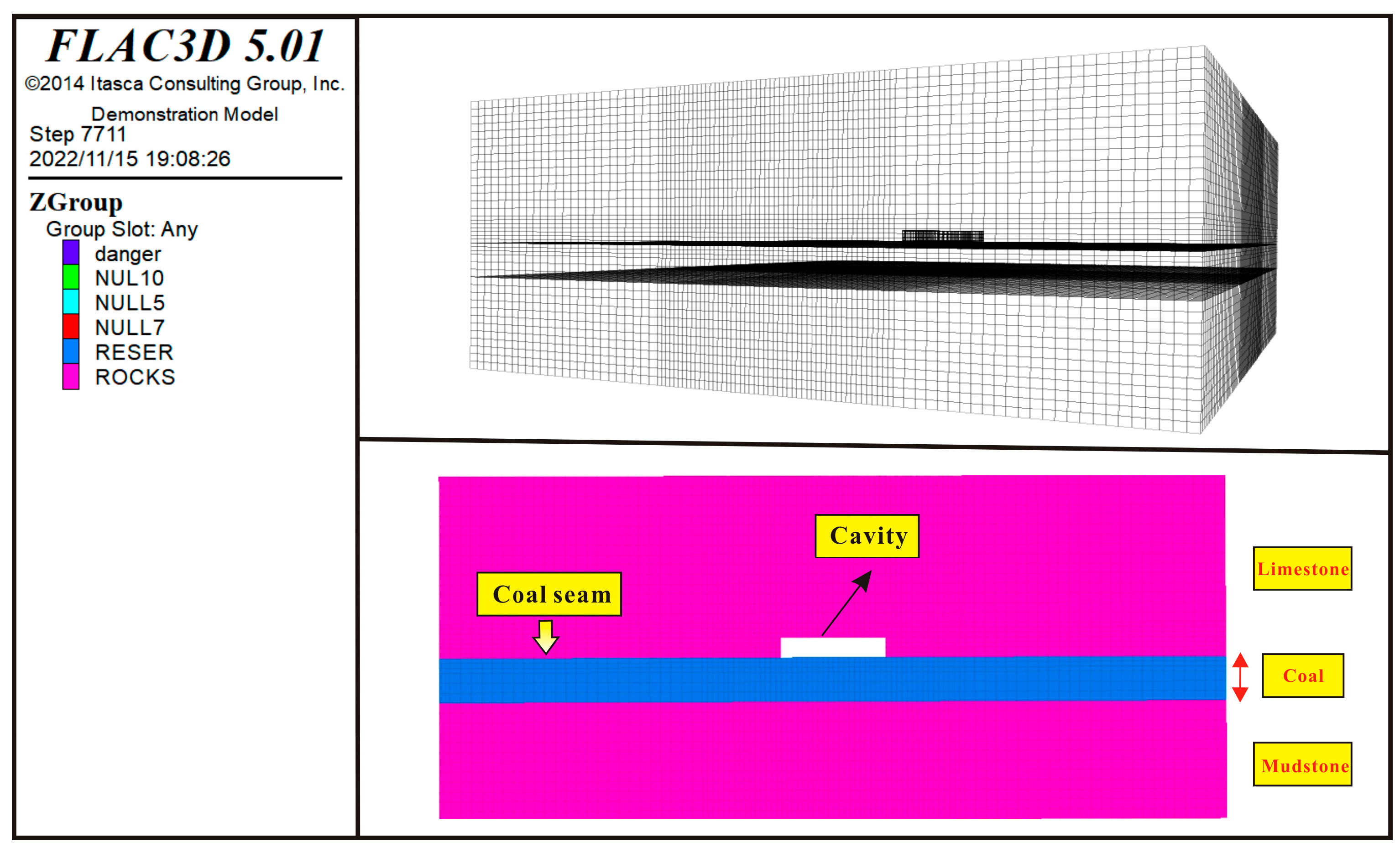
2.3.1. Modeling Geometric of Numerical Model

To analyze the stress impact on the eighth coal seam after the formation of the roof cave, a three-dimensional numerical simulation model was established using the FLAC3D software (version 5.01, Itasca Consulting Group, Inc., Minneapolis, MN, USA) by combining the geological conditions obtained from the pre-exploration of the deep CBM in the Daning-Jixian area. Since the undulation of the eighth coal seam in the Daning-Jixian area has a small variation with an average dip angle of 6°, it belongs to the near-horizontal coal seam, and most of its internal sections of coal seams are horizontally distributed, so the modeling was simplified to deal with horizontal coal seams [43].
Therefore, a numerical model of 200 m × 100 m × 100 m was established by combining the coal distribution in the comprehensive geological column map of the study area. The roof slab of the model is limestone, the floor slab is mudstone, and the thickness of the middle coal seam is 8 m. The model is drilled into the coal seam at the surface through a vertical well and a roof cave with a length of 20 m and a height of 2 m is formed by disturbing along the coal seam (Figure 1).

2.3.2. Boundary Conditions and Assignment Loading

The left, right, and lower boundaries of the model are the displacement fixed constraint boundaries and the upper boundary is the stress boundary; the uniform load is applied according to the thickness of the overlying rock layer. The material model parameters are assigned according to the lithology of different rock layers, and the rock mechanics parameters are obtained through the rock mechanics experiments conducted by the subject group on the area, as shown in Table 1.

3. Results and Analysis

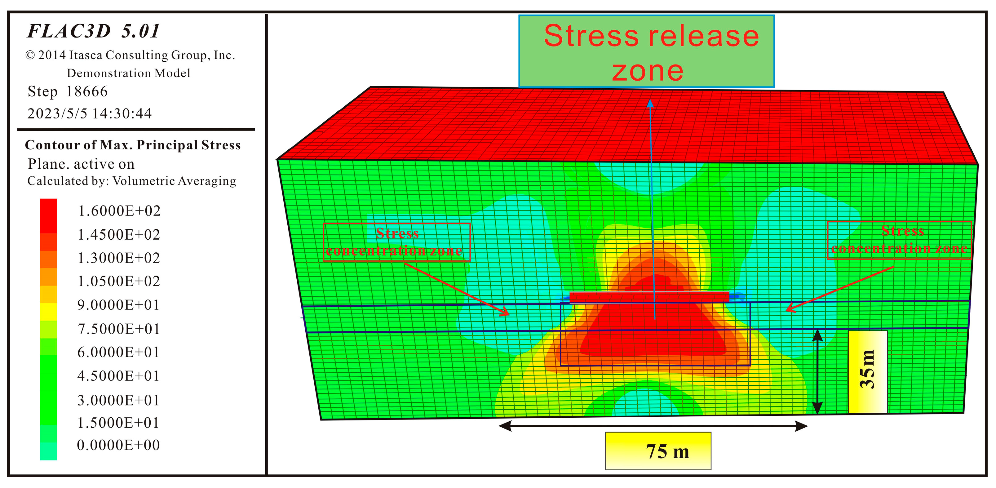
3.1. The Distribution of Reservoir Stress Under Cave Disturbance

In the Daning-Jixian area, the deep coalbed methane (CBM) reservoir exhibits specific geological characteristics, with limestone serving as the main roof rock of the eighth coal seam. Due to its high rock mechanical strength and underdeveloped cleats and fractures, the limestone maintains its structural integrity after cavity excavation. Consequently, the overall mechanical properties of the roof limestone do not degrade significantly, preventing phenomena such as delamination, subsidence, or collapse.
Following cavity excavation in the roof of the vertical well, intense ground engineering disturbance disrupts the in situ stress, leading to a redistribution of the stress field. Figure 2 presents a nephogram illustrating the vertical principal stress distribution in the reservoir after roof cavitation. The stress release zone (red) exhibits a rapid decline in vertical stress within the roof and floor strata, which is most pronounced within 0–50 m of the cavity walls (both vertically above and below), where stress reversal phenomena (reverse resistance) may occur. The in situ stress zone (green) maintains near-original in situ stress conditions, with principal stresses averaging 17.5 MPa. Consistent with energy conservation principles, stress redistribution generates two symmetrical stress concentration zones (blue) flanking the cavity laterally, where vertical principal stresses intensify to values exceedingly twice the in situ stress (up to 38 MPa).
Analysis of the stress nephogram reveals that, in cases where limestone forms the immediate roof, the cavern-induced stress release zone predominantly develops beneath the excavation. The coal seam and floor mudstone exhibit significantly lower maximum counter stress resistance compared to the roof limestone, resulting in an expanded stress release zone at the base of the cavity (Figure 2).
Figure 3 and Figure 4 present the vertical principal stress distribution nephograms for reservoir caverns with diameters of 40 m and 50 m, respectively. While the fundamental stress distribution pattern remains largely consistent across different cavern sizes (30 m to 50 m diameter), the stress release area exhibits significant expansion with increasing cavern diameter. Quantitative analysis reveals that the stress release zone volumes measure 11,520 m3, 15,232 m3, and 18,544 m3 for cavern diameters of 30 m, 40 m, and 50 m, respectively. Correspondingly, the stress concentration zone volumes are 9700 m3, 9840 m3, and 15,232 m3 for these diameters (Figure 5).

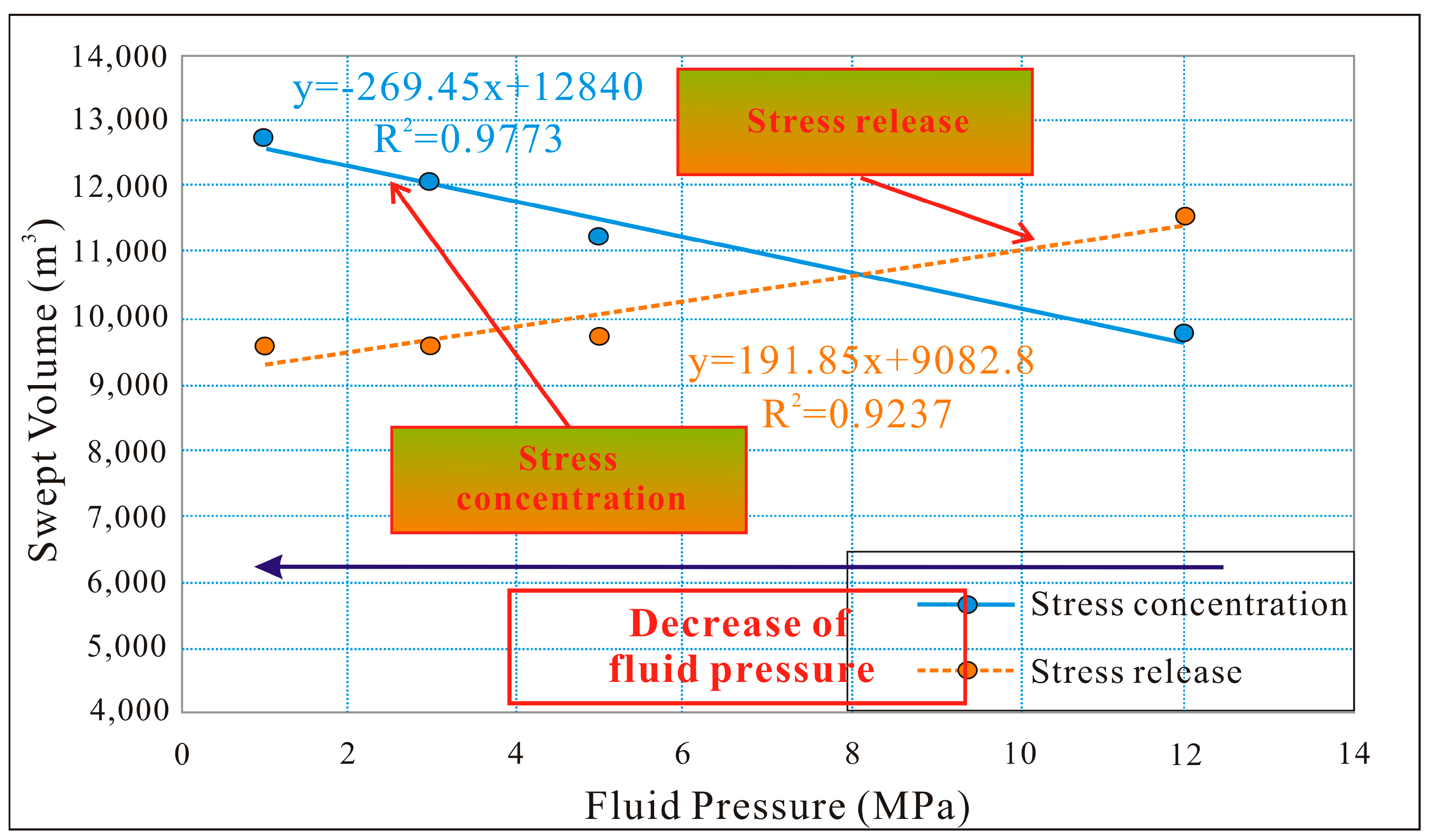
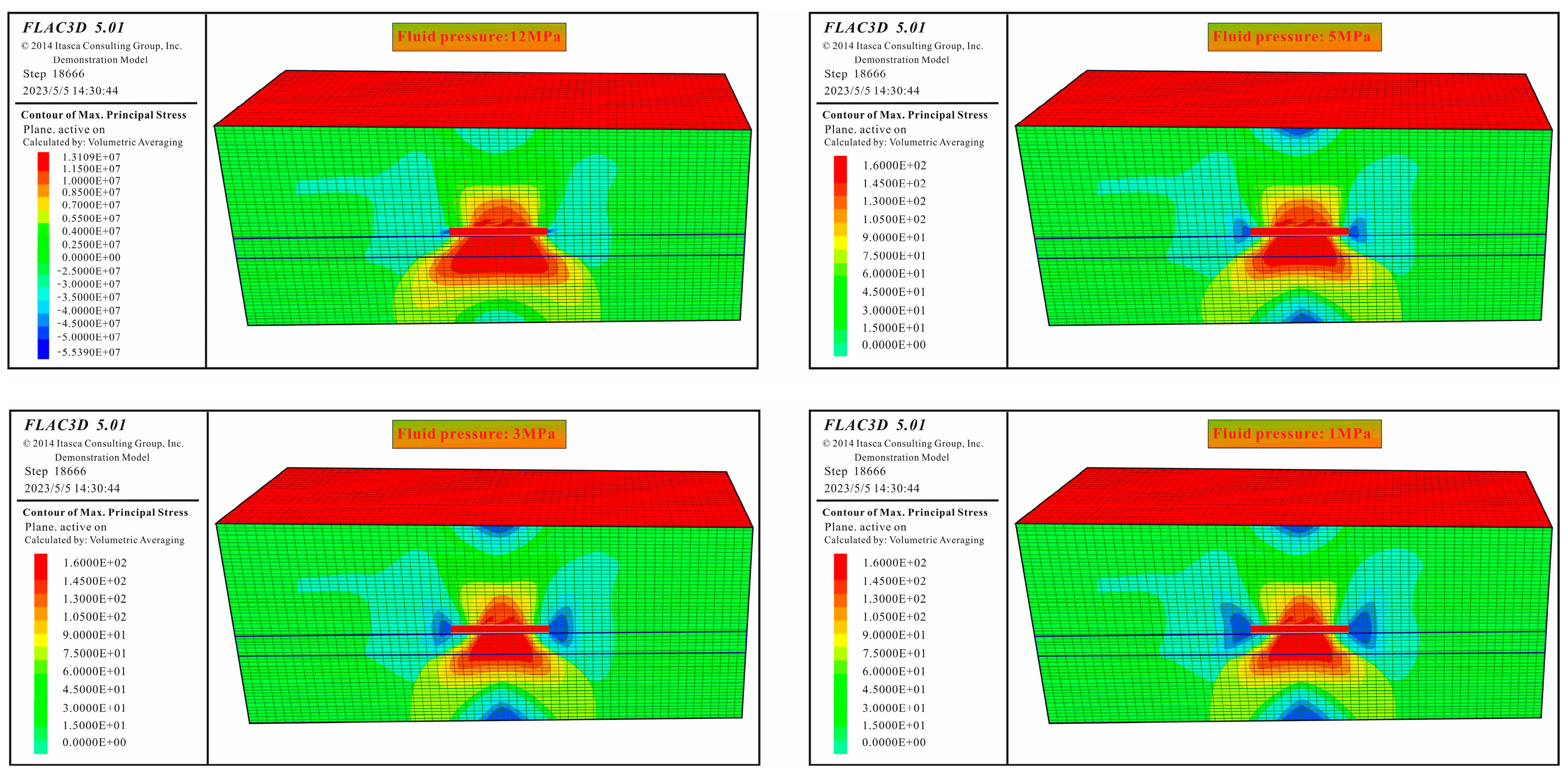
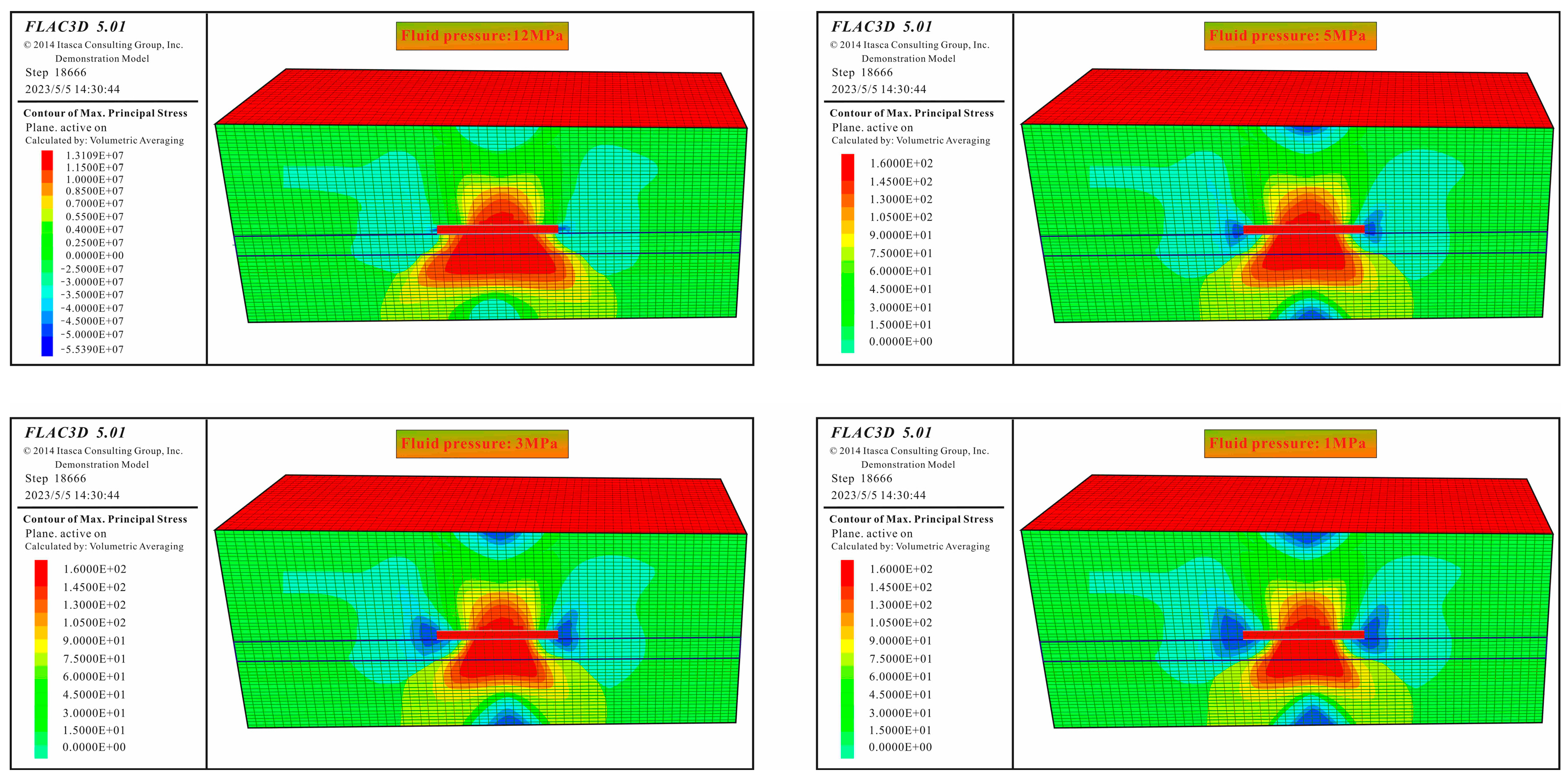
3.2. Reservoir Stress Release Under Different Fluid Pressures

During CBM extraction, the effective stress within reservoirs is governed by overburden stress, tectonic stress, and fluid pressure. Cavity completion drilling induces localized reductions in skeleton stress (potentially to zero), creating stress release zones. This stress reduction significantly decreases effective compressive stress and may even generate tensile stress. However, continuous fluid pressure depletion during dewatering production alters the effective stress distribution, thereby modifying the spatial extent of stress release and stress concentration zones. To elucidate stress evolution characteristics across production stages, the dynamic boundaries of these zones under varying fluid pressures were quantitatively evaluated in this study.
Figure 6 presents the vertical stress distribution patterns in the reservoir under varying fluid pressure conditions. The results demonstrate that the resistance at both the roof and floor boundaries progressively intensifies, causing increased stress concentration in these areas. This concentrated stress then propagates upward, leading to a corresponding decrease in the spatial extent of the stress-relieved zone within the reservoir’s central region. Furthermore, distinctive bilateral stress concentration features, exhibiting ear-shaped configurations (shown in blue), develop adjacent to the cavity, exerting compressive forces on the underlying coal reservoir.
The numerical simulations reveal a direct correlation between decreasing fluid pressure and the expansion/magnification of these peripheral stress concentration zones. This phenomenon stems from the continuous drainage process, where reduced near-wellbore fluid pressure creates a pressure gradient that drives fluid migration from distal coal seams toward the wellbore region. Consequently, this fluid displacement results in additional pressure depletion in remote coal sections, which, in turn, enhances both the spatial coverage and magnitude of the stress concentration surrounding the cavity.
The statistical analysis reveals distinct volumetric changes in stress distribution under varying fluid pressures. At an initial pressure of 12 MPa, the reservoir exhibits a stress release volume of 11,520 m3 alongside a stress concentration volume of 9700 m3. Following pressure depletion to 1 MPa, the stress release volume contracts significantly to 9540 m3 (17% reduction), while the stress concentration volume expands markedly to 12,700 m3 (31% increase). This inverse relationship between pressure reduction and stress redistribution demonstrates that prolonged drainage operations promote (1) the progressive expansion of stress concentration zones and (2) the corresponding shrinkage of stress release regions (Figure 7).
Upon increasing the cavity diameter to 40 m and 50 m, while the total volume of the stress release zone exhibits expansion, a progressive contraction of this zone is nevertheless observed with continued fluid pressure depletion (Figure 8 and Figure 9). Conversely, the stress concentration zone demonstrates a systematic expansion under the same conditions. This phenomenon can be attributed to drainage-induced pressure differentials that promote fluid migration from distal coal seams toward the proximal wellbore region. The resultant pressure depletion in distal formations subsequently enhances both the spatial extent and magnitude of stress concentration surrounding the cavity.

3.3. Permeability Evolution Under Stress Release Effect

Stress release has emerged as a viable production enhancement technique for efficient CBM extraction, with its feasibility and reliability having been theoretically verified. However, research on deep CBM permeability evolution under stress release conditions remains in its nascent stage, significantly impeding the practical application of stress-release-based production enhancement technologies. Consequently, this study establishes the stress release mechanisms under cavitation disturbance, quantitatively analyzes the correlation between cavitation-induced stress release and permeability, and determines the permeability evolution patterns in deep coal reservoirs under stress release effects.
The simulation results demonstrate a strong correlation between coal reservoir permeability distribution and vertical stress distribution (Figure 2 and Figure 10), where increased stress release corresponds to higher permeability. Within the coal seam’s stress release zone, permeability (initial value: 1.2 mD) can increase to 5.8 mD. Conversely, in stress concentration areas where compressive stresses dominate, permeability decreases by 50–70% compared to initial values. These findings confirm that cavitation-induced reservoir stress changes effectively regulate coal seam permeability variations.
The comparative analysis of reservoir permeability evolution under varying fluid pressures reveals two key trends: (1) The stress concentration zone progressively expands with decreasing fluid pressure, leading to a corresponding increase in permeability impairment range. (2) Concurrently, both the stress release area and associated permeability enhancement zone gradually diminish during the drainage process.

4. Sequential-Cavity-Induced Stress Release for Horizontal Wells

Roof cavity formation creates expansive stress release zones in coal reservoirs, enhancing permeability. However, based on the principle of energy conservation, energy is not eliminated, but rather redistributed to the cavity boundaries, forming large-scale stress concentration zones at both ends of the cavity, which adversely impacts reservoir development. Continued drainage reduces fluid pressure, causing stress concentration zones to expand into stress-relieved areas, progressively diminishing permeability enhancement. While cavity completion relieves local stress, its limited energy transfer fails to induce cyclic tensile–shear stresses in distal strata, yielding suboptimal stimulation. Thus, broader stress release strategies are imperative for effective reservoir modification.

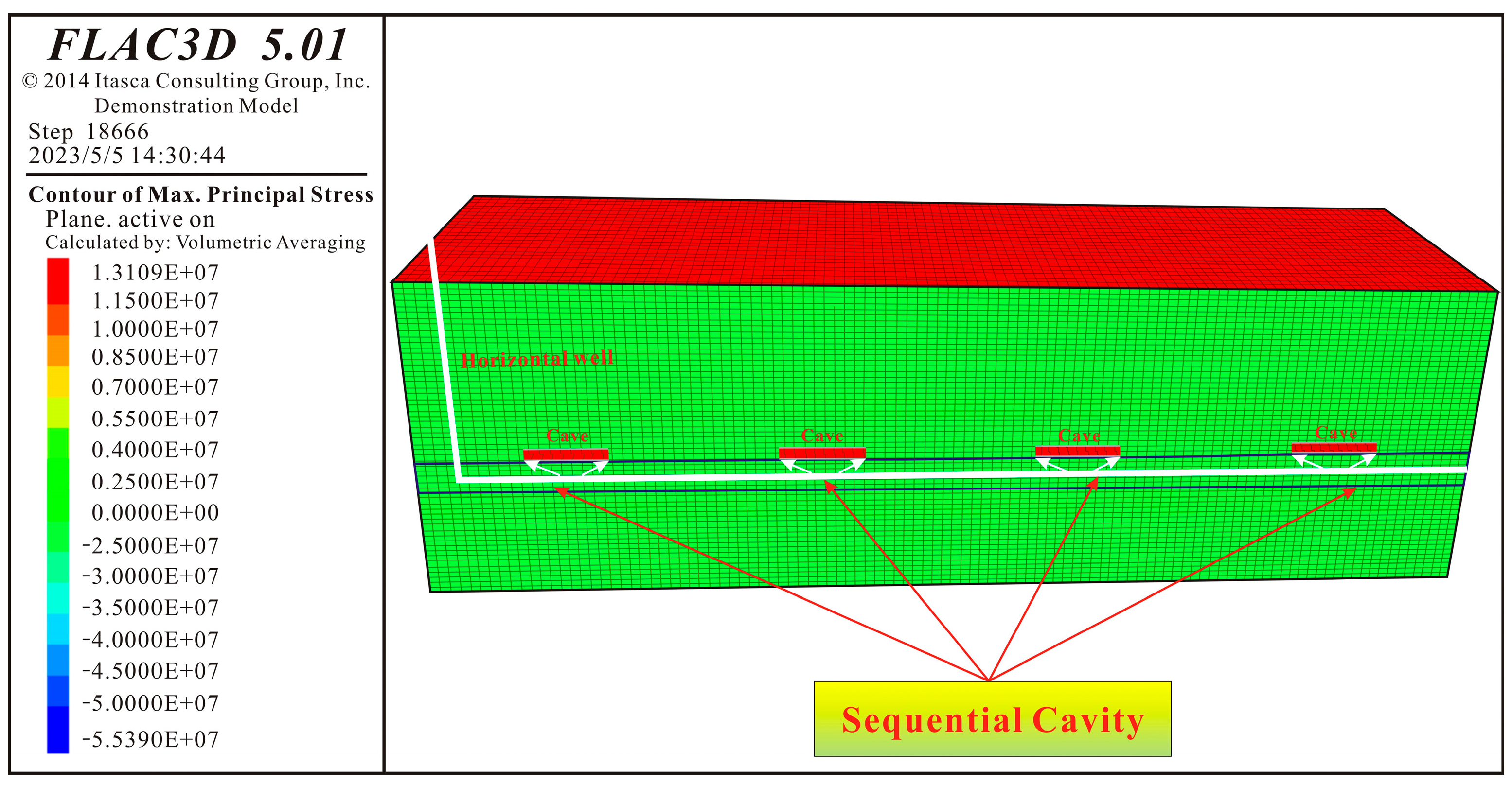
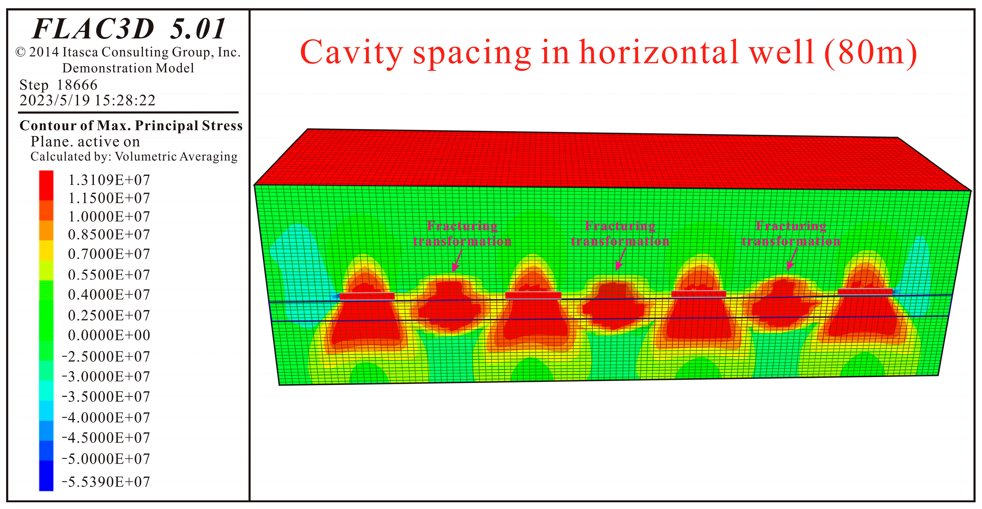
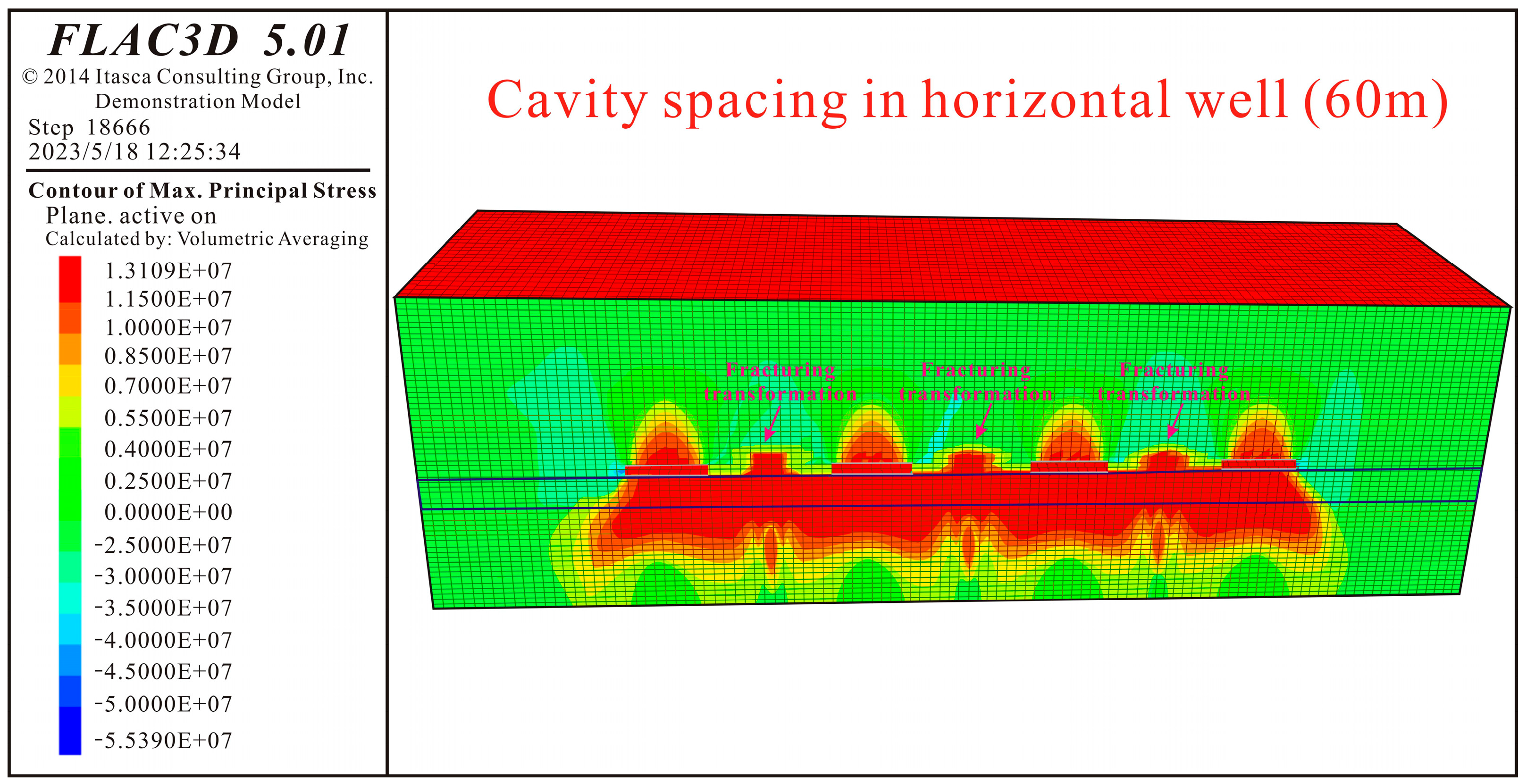
4.1. Stress Distribution of Sequential Cavity Completion for Horizontal Wells

Sequential cavity completion in large-diameter horizontal wells emerges as a strategic reserve technology for coalbed methane (CBM) production, addressing critical limitations in stress release scope while enhancing coal seam permeability. To overcome the constrained stress release range, optimize fracture networks, and amplify pressure release efficiency, we developed a 3D FLAC3D model simulating roof cavity completion in horizontal wells. This framework enables the systematic investigation of cavity-induced stress redistribution mechanisms for improved CBM stimulation technology (Figure 11).
Figure 12 presents the vertical stress distribution nephogram of a coal reservoir with 80 m cavity spacing in a horizontal well. The simulation results demonstrate that stress release zones predominantly develop beneath cavity completion points, enhancing reservoir permeability. Consistent with energy conservation principles, stress redistribution generates bilateral stress concentration zones at cavity peripheries, rather than dissipating.
Crucially, sequential cavity completion exhibits distinct stress superposition effects compared to single-cavity scenarios. While both configurations produce cavity edge stress concentrations, sequential operations induce overlapping stress fields between adjacent cavities. Larger inter-cavity spacing exacerbates this superposition, subjecting significant portions of the inter-cavity coal mass to compounded stress impacts (Figure 12).
Building upon previous findings, the cavity spacing in horizontal wells was reduced to 60 m (Figure 13). The results demonstrate that decreasing inter-cavity distance compresses the terminal stress concentration zones through stress release zone expansion, effectively mitigating stress superposition effects. Simulation analyses further reveal that closer cavity spacing not only reduces stress concentration overlap, but also induces the coalescence of sub-cavity stress release zones, forming continuous superimposed stress release regions (Figure 13). However, with larger spacing configurations, these superimposed stress release zones predominantly localize near the coal seam floor, providing limited enhancement to reservoir permeability.
Figure 14 presents the vertical stress distribution contour map of coal reservoirs under a horizontal well cavity spacing of 40 m. The simulation results reveal that, at this cavity spacing, the stress release zone beneath the horizontal well cavities significantly compresses the stress concentration superposition zone within the coal reservoirs. This interaction drives two critical outcomes: (1) the stress release zone in the coal seam undergoes continuous expansion and (2) the stress concentration superposition zone experiences further contraction. Notably, when the cavity spacing is reduced to 40 m, the stress release zone occupies approximately 50% of the original stress concentration superposition area near the cavity ends.
Furthermore, numerical modeling demonstrates that the stress release superposition zone within the coal seam floor exhibits both vertical expansion and upward migration, extending its influence to adjacent coal reservoir regions near the cavity ends. These observations highlight that a 40 m cavity spacing not only intensifies the compression of the stress concentration zone by the stress release region, but also activates floor-derived stress release effects (Figure 14). Specifically, the upward-propagating stress release superposition zone interacts with intermediate coal seams, enhancing permeability in the central coal reservoir.
After increasing the spacing between horizontal well cavities to 20 m, the stress distribution cloud map (Figure 15) shows that the stress release superposition zone gradually extends from the coal seam floor into the coal seam itself, nearly eliminating all stress concentrations.
The results indicate that reducing the spacing between cavities creates a superimposed stress release zone beneath the cavities, connecting pressure reduction areas in the coal seam. This minimizes stress concentration effects on coal reservoirs, thereby enhancing gas production capacity.

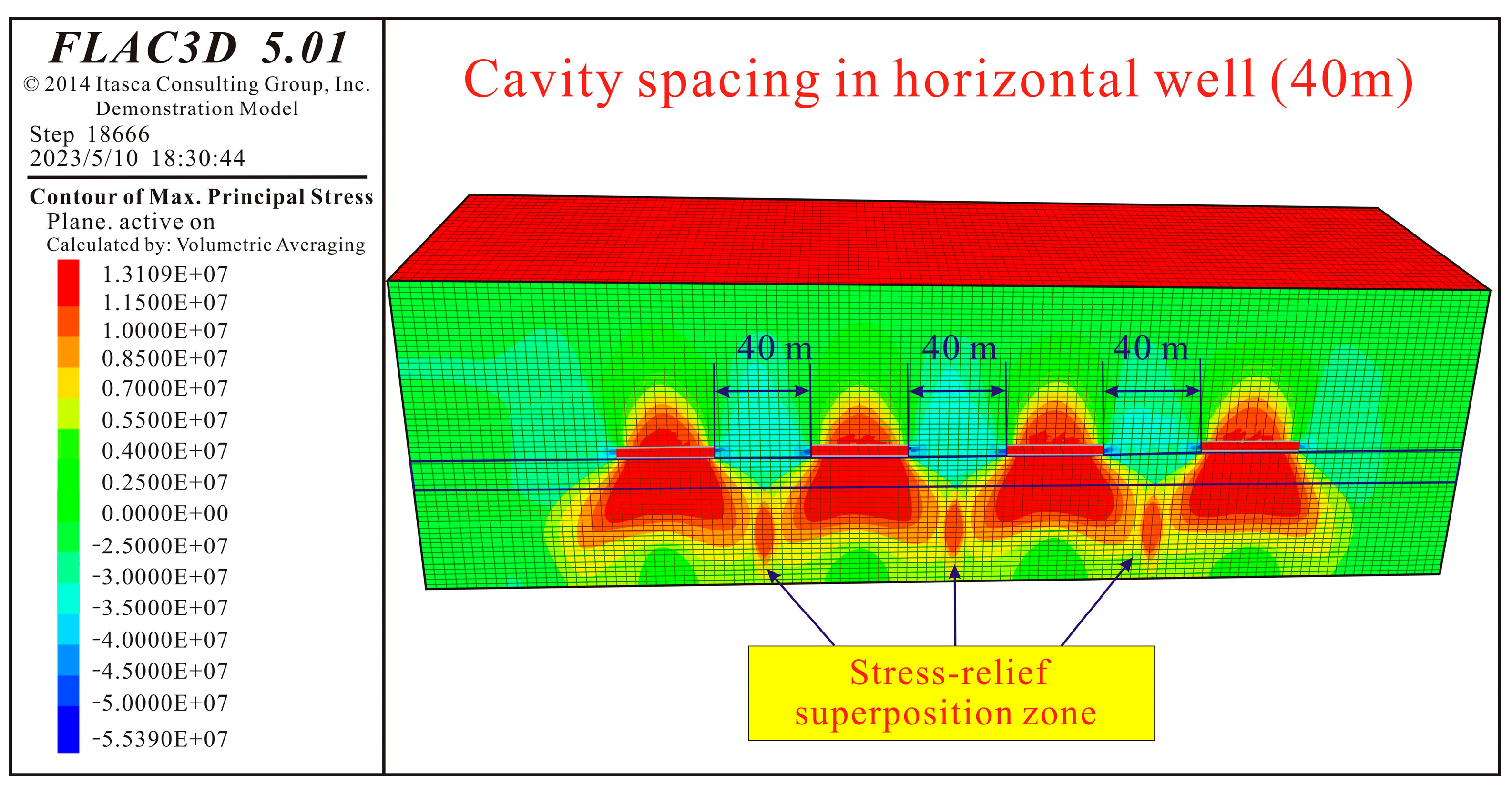
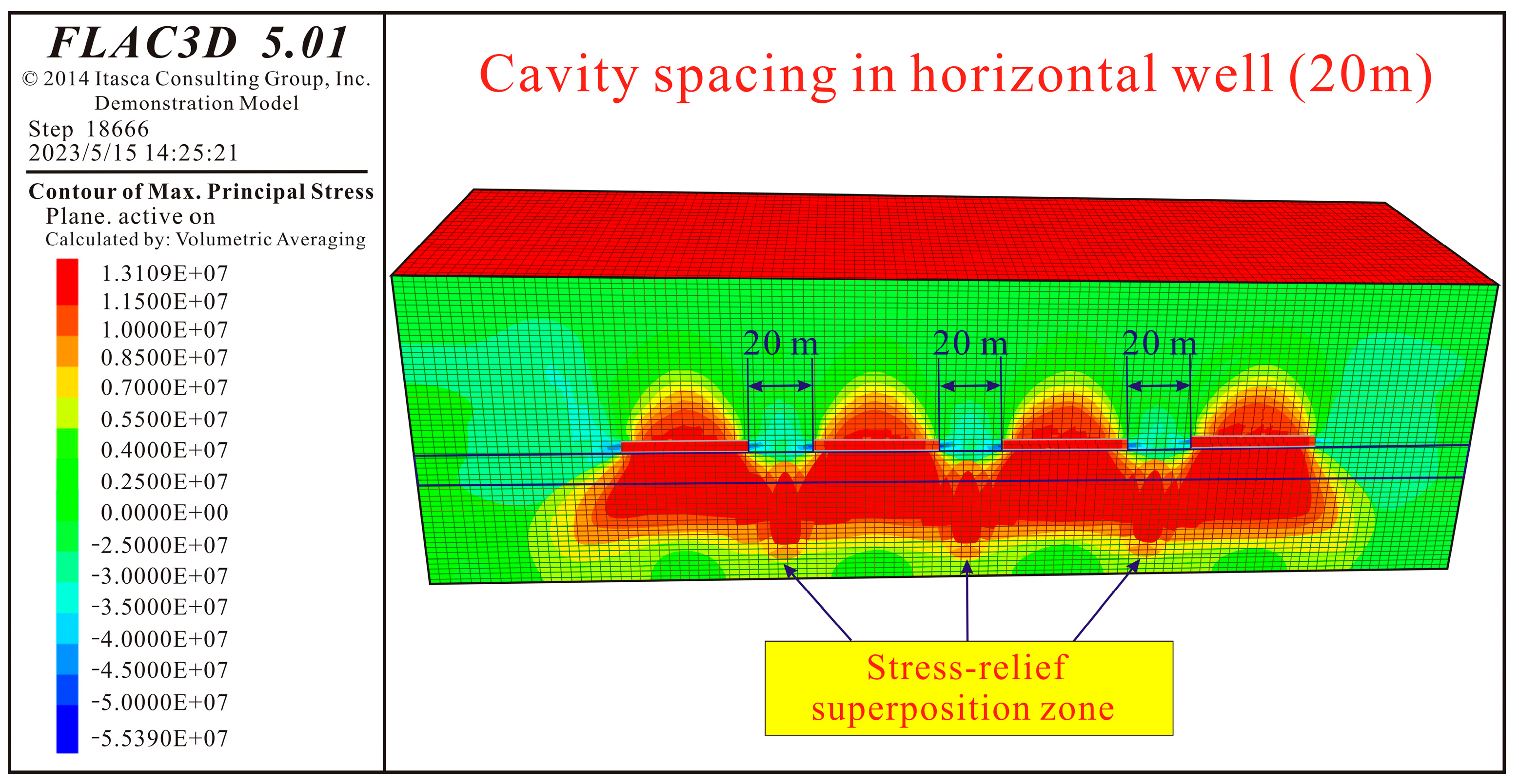
4.2. Sequential Cavity Completion for Stress Release in Horizontal Wells

The spatial dimensions, geometric configuration, quantity, cluster spacing, and placement of cavities in horizontal wells govern the extent of stress release propagation and reservoir permeability enhancement, thereby determining the effectiveness of cavity-induced stimulation. These cavity parameters require optimization based on specific geological and reservoir conditions to maximize pressure release and permeability improvement.
Simulation results reveal significant stress concentrations at both ends of individual cavities. The superposition of these stress concentrations subjects the coal seam between consecutive cavities to a compounded stress concentration effect. While reducing the spacing between cavities can effectively mitigate stress concentration zones at the coal seam boundaries, this approach inevitably escalates development costs. To address this challenge, a hybrid stimulation technology integrating continuous cavity completion with hydraulic fracturing is proposed for coalbed methane (CBM) horizontal wells.
When cavity spacing is excessive (80 m), stress release superposition cannot occur, and significant compounded stress concentration zones develop at cavity ends (Figure 16). To address this, targeted hydraulic fracturing is applied to stress-concentrated coal reservoirs, effectively neutralizing cavity-induced stress concentrations. Figure 16 presents the vertical stress distribution under the hybrid cavity-fracturing technology. Simulations demonstrate that hydraulic fracturing in stress-concentrated zones generates elevated fluid pressure, which mechanically supports the coal seam, counteracts compressive stress effects, and enhances permeability in deep coal reservoirs.
Figure 17 shows the vertical stress distribution cloud map of the hybrid cavity-fracturing stimulation technology with a cavity spacing of 60 m. Simulation results reveal that, when the spacing between continuous cavities in horizontal wells is 60 m, targeted hydraulic fracturing applied to stress-concentrated coal seams at cavity ends induces elevated fluid pressure in the compounded stress concentration zones. This effectively counteracts stress-induced compression and enhances reservoir stimulation effectiveness.
The simulations further demonstrate that larger cavity spacing leads to extensive stress concentration zones at cavity ends, which impair reservoir modification. Implementing targeted hydraulic fracturing in these stress-concentrated areas during continuous cavity completion generates high fluid pressure, mitigating compressive stress effects and optimizing coal reservoir permeability.

5. Conclusions

This study established a fully hydromechanically coupled 3D distinct element model using FLAC3D software to simulate and investigate stress variations and reservoir permeability evolution under stress release effects. Through the comparative analysis of stress release effects and permeability evolution at different fluid pressures, we developed an enhanced CBM extraction methodology that simultaneously expands stress release zones while mitigating stress concentration areas. The insights of the work are as follows:
(1)
Conventional discrete models for coalbed stress release are limited to shallow protective layer mining scenarios and neglect critical mechanisms governing deep coalbed methane (CBM) systems, including high in situ stresses, non-linear elastoplastic deformation, and cavitation-induced stress perturbations. To address this gap, a novel stress–seepage coupling framework is proposed by considering the elastoplastic transition mechanisms during stress release, fluid pressure dynamics, and rock–fluid interactions involving diffusion/adsorption-induced deformation. The model uniquely resolves permeability evolution during deep stress redistribution triggered by cavity formation, advancing fundamental insights into stress–seepage interdependencies.
(2)
Aiming at the complex conditions of high stress and non-linear deformation in deep coalbed methane reservoirs, the fully coupled fluid–solid mechanics 3D discrete element model (FLC3D) was established, quantitatively revealing the asymmetric impact of dynamic fluid pressure changes on permeability. This study found that, when fluid pressure decreases from 12 MPa to 1 MPa, the stress release zone volume shrinks by 17%, while the stress concentration zone expands by 31%. Permeability in the release zone can increase to 5.8 mD (a 483% enhancement), whereas it declines by 50–70% in the concentration zone. This dynamic evolution pattern provides critical theoretical guidance for optimizing drainage parameters in deep reservoirs.
(3)
This work proposes an innovative sequential cavity completion–hydraulic fracturing synergistic technology, overcoming the limitations of traditional single-method approaches. By actively injecting high-pressure fluid into stress concentration zones at the cavity ends through hydraulic fracturing, the compressive stress effect is directly counteracted (peak stress reaches 2.54 times the initial value), achieving the dynamic neutralization of stress concentration zones and permeability restoration. This combined technology not only expands the stress release range, but also addresses the energy transfer constraints caused by high stress in deep reservoirs, providing a new engineering paradigm for deep coalbed methane development.

Author Contributions

Conceptualization, K.W.; Data curation, Z.W.; Formal analysis, H.Z. (Huaibin Zhen) and G.C.; Investigation, Y.L., Z.W., C.W. and G.C.; Methodology, K.W. and S.L.; Project administration, H.Z. (Haifeng Zhao) and K.W.; Resources, Z.W.; Software, Y.L.; Supervision, S.L. and G.C.; Validation, S.L. and C.W.; Visualization, Y.L.; Writing—original draft, H.Z. (Huaibin Zhen) and H.Z. (Haifeng Zhao); Writing—review and editing, H.Z. (Haifeng Zhao), S.L. and C.W. All authors have read and agreed to the published version of the manuscript.

Funding

This study is jointly supported by the National Natural Science Foundation of China (NO: 52174017); Open fund of the Key Laboratory of geothermal resources of the Ministry of natural resources (NO: KLDGR2022G05); and Open Fund of Hubei Key Laboratory of Drilling and Production Engineering for Oil and Gas (Yangtze University) (NO: YQZC202104).

Data Availability Statement

The original contributions presented in this study are included in the article. Further inquiries can be directed to the corresponding author.

Conflicts of Interest

Authors Huaibin Zhen, Shuguang Li, Zhenji Wei and Chengwang Wang were employed by the Petro China Coalbed Methane Co., Ltd. and China United Coalbed Methane National Engineering Research Center Co., Ltd. The remaining authors declare that the research was conducted in the absence of any commercial or financial relationships that could be construed as a potential conflict of interest.

References

  1. Xu, H.; Tang, D.; Mathews, J.P.; Zhao, J.; Li, B.; Tao, S. Evaluation of coal macrolithotypes distribution by geophysical logging data in the Hancheng Block, Eastern Margin, Ordos Basin, China. Int. J. Coal Geol. 2016, 165, 265–277. [Google Scholar] [CrossRef]
  2. Li, S.; Qin, Y.; Tang, D.; Shen, J.; Wang, J.; Chen, S. A comprehensive review of deep coalbed methane and recent developments in China. Int. J. Coal Geol. 2023, 279, 104369. [Google Scholar] [CrossRef]
  3. Liu, Y.; Xu, H.; Tang, D.; Mathews, J.P.; Zhai, Y.; Hou, W. The impact of the coal macrolithotype on reservoir productivity, hydraulic fracture initiation and propagation. Fuel 2019, 239, 471–483. [Google Scholar] [CrossRef]
  4. Fan, T.; Zhang, G. Laboratory investigation of hydraulic fracture networks in formations with continuous orthogonal fractures. Energy 2014, 74, 164–173. [Google Scholar] [CrossRef]
  5. Meng, S.; Hou, B.; Zhang, J. Experimental research on hydraulic fracture propagation through mixed layers of shale, tight sand and coal seam. J. China Coal Soc. 2016, 41, 221–227. [Google Scholar]
  6. Li, Q.; Li, Q.C.; Wu, J.; Li, X.; Li, H.; Cheng, Y. Wellhead Stability During Development Process of Hydrate Reservoir in the Northern South China Sea: Evolution and Mechanism. Processes 2025, 13, 40. [Google Scholar] [CrossRef]
  7. Li, Q.; Li, Q.C.; Cao, H.; Wu, J.; Wang, F.; Wang, Y. Analysis of casing deformation failure mechanism based on fault slip. Processes 2025, 13, 159. [Google Scholar] [CrossRef]
  8. Shi, R.; Liu, J.; Wei, M.; Derek, E.; Wang, X. Mechanistic analysis of coal permeability evolution data under stress-controslled conditions. Int. J. Coal Geol. 2018, 110, 36–47. [Google Scholar]
  9. Souley, M.; Renaud, V.; AlHeib, M.; Bouffier, C.; Lahaie, F.; Nyström, A. Numerical investigation of the development of the excavation damaged zone around a deep polymetallic ore mine. Int. J. Rock Mech. Min. Sci. 2018, 106, 165–175. [Google Scholar] [CrossRef]
  10. Xie, H.; Zhao, X.; Liu, J.; Zhang, R. Influence of different mining layouts on the mechanical properties of coal. Int. J. Min. Sci. Technol. 2012, 22, 749–755. [Google Scholar] [CrossRef]
  11. Vazaios, I.; Vlachopoulos, N.; Diederichs, M. Assessing fracturing mechanisms and evolution of excavation damaged zone of tunnels in interlocked rock masses at high stresses using a finite-discrete element approach. J. Rock Mech. Geotech. Eng. 2019, 11, 701–722. [Google Scholar] [CrossRef]
  12. Sang, S.; Xu, H.; Fang, L.; Li, G.; Huang, H. Stress relief coalbed methane drainage by surface vertical wells in China. Int. J. Coal Geol. 2010, 82, 196–203. [Google Scholar] [CrossRef]
  13. Shi, J.; Durucan, S. Drawdown induced changes in permeability of coalbeds: A new interpretation of the reservoir response to primary recovery. Transp. Porous Media 2004, 56, 1–16. [Google Scholar] [CrossRef]
  14. Kong, X.; Wang, E.; Liu, Q.; Li, Z.; Li, D.; Cao, Z.; Niu, Y. Dynamic permeability and porosity evolution of coal seam rich in CBM based on the flow-solid coupling theory. J. Nat. Gas Sci. Eng. 2017, 40, 6–25. [Google Scholar] [CrossRef]
  15. Duan, M.; Jiang, C.; Xing, H.; Zhang, D.; Peng, K.; Zhang, W. Study on damage of coal based on permeability and load-unload response ratio under tiered cyclic loading. Arab. J. Geosci. 2020, 13, 250. [Google Scholar] [CrossRef]
  16. Zeng, K.; Xu, J.; He, P.; Wang, C. Experimental Study on Permeability of Coal Sample Subjected to Triaxial Stresses. Procedia Eng. 2011, 26, 1051–1057. [Google Scholar] [CrossRef]
  17. Ben, A.; Aubertin, M.; Simon, R. Numerical simulations of water flow and contaminants transport near mining wastes disposed in a fractured rock mass. Int. J. Min. Sci. Technol. 2015, 25, 37–45. [Google Scholar]
  18. Lisjak, A.; Figi, D.; Grasselli, G. Fracture development around deep underground excavations: Insights from FDEM modelling. J. Rock Mech. Geotech. Eng. 2014, 6, 493–505. [Google Scholar] [CrossRef]
  19. Vaziri, H.H.; Palmer, I.D. Evaluation of openhole cavity completion technique in coalbed methane reservoirs. Int. J. Rock Mech. Min. Sci. 1998, 35, 523–524. [Google Scholar] [CrossRef]
  20. Sang, S.; Zhou, X.; Liu, S. Research advances in theory and technology of the stress release applied extraction of coalbed methane from tectonically deformed coals. J. China Coal Soc. 2020, 45, 13–28. [Google Scholar]
  21. Yang, R.; Huang, Z.; Li, G.; Chen, J.; Wen, H.; Qin, X. Feasibility Investigation of Hydraulic jet multistage cavity completion in coalbed methane horizontal wells. J. China Coal Soc. 2022, 47, 3284–3298. [Google Scholar]
  22. Xie, H.; Xie, J.; Gao, M.; Zhang, R.; Zhou, H.; Gao, F. Theoretical and experimental validation of mining-enhanced permeability for simultaneous exploitation of coal and gas. Environ. Earth Sci. 2015, 73, 5951–5962. [Google Scholar] [CrossRef]
  23. Taheri, A.; Sereshki, F.; Doulati, A.; Mirzaghorbanali, A. Numerical modeling of gas flow in coal pores for methane drainage. J. Sustain. Min. 2016, 15, 95–99. [Google Scholar] [CrossRef]
  24. Xue, Y.; Ranjith, P.; Gao, F.; Zhang, D.; Cheng, H.; Chong, Z.; Hou, P. Mechanical behaviour and permeability evolution of gas-containing coal from unloading confining pressure tests. J. Nat. Gas Sci. Eng. 2017, 40, 336–346. [Google Scholar] [CrossRef]
  25. Wang, Z.; Sang, S.; Zhou, X.; Liu, S.; Wang, H.; Shu, Y. Response in coal reservoirs and in-situ stress control during horizontal well coal cavern completion and stress release. Gas Sci. Eng. 2023, 113, 204950. [Google Scholar] [CrossRef]
  26. Qian, M.; Xu, J. Study on the “O-shape” circle distribution characteristics of mining-induced fractures in the overlying strata. J. China Coal Soc. 1998, 23, 466–469. [Google Scholar]
  27. Qian, M. A Study of the Behaviour of Overlying Strata in Longwall Mining and its Application to Strata Control. Strat. Mech. 1982, 1, 13–17. [Google Scholar]
  28. Qian, M. Theory and Practice of Surrounding Rock Control in Stopes. J. Min. Saf. Eng. 1999, 29, 12–15. [Google Scholar]
  29. Du, X. Research on the Evolution and Its Application of Rock Pressure Arch in Coal Mining; China University of Mining and Technology: Xuzhou, China, 2011. [Google Scholar]
  30. Pan, Z.; Connell, L. Modelling of anisotropic coal swelling and its impact on permeability behaviour for primary and enhanced coalbed methane recovery. Int. J. Coal Geol. 2011, 85, 257–267. [Google Scholar] [CrossRef]
  31. Li, Q.; Deng, Y.; Li, J.; Shi, W. Roughness characterization and formation mechanism of abrasive air jet micromachining surface studied by power spectral density. J. Manuf. Process. 2020, 57, 737–747. [Google Scholar] [CrossRef]
  32. Yin, G.; Jiang, C.; Wang, J.; Jiang, X. Geomechanical and flow properties of coal from loading axial stress and unloading confining pressure tests. Int. J. Rock Mech. Min. Sci. 2015, 76, 155–161. [Google Scholar] [CrossRef]
  33. Cui, W.; Liu, Q.; Wu, Z.; Xu, X. Fracture development around wellbore excavation: Insights from a 2D thermo-mechanical FDEM analysis. Eng. Fract. Mech. 2024, 295, 109774. [Google Scholar] [CrossRef]
  34. Zhang, Z.; Zhang, R.; Xie, H.; Gao, M.; Zha, E.; Jia, Z. An anisotropic coal permeability model that considers mining-induced stress evolution, microfracture propagation and gas sorption-desorption effects. J. Nat. Gas Sci. Eng. 2017, 46, 664–679. [Google Scholar] [CrossRef]
  35. Liu, Y.; Wei, K.; Wang, A.; Fang, Q.; Wang, C. Dynamic Permeability Response and Pore-Fracture Structure Evolution of Deep Coal Reservoirs Under Stress Release. Nat. Resour. Res. 2025, 34, 953–982. [Google Scholar] [CrossRef]
  36. Lisjak, A.; Grasselli, G.; Vietor, T. Continuum-discontinuum analysis of failure mechanisms around unsupported circular excavations in anisotropic clay shales. Int. J. Rock Mech. Min. Sci. 2014, 65, 96–115. [Google Scholar] [CrossRef]
  37. Xue, Y.; Gao, F.; Gao, Y.; Cheng, H.; Liu, Y.; Hou, P. Quantitative evaluation of stress relief and permeability-increasing effects of overlying coal seams for coal mine methane drainage in Wulan coal mine. J. Nat. Gas Sci. Eng. 2016, 32, 122–137. [Google Scholar] [CrossRef]
  38. Robertson, E.; Christiansen, R. A Permeability model for coal and other fractured, sorptive-elastic media. SPE J. 2006, 13, 314–324. [Google Scholar] [CrossRef]
  39. Hong, C.; Yang, R.; Huang, Z.; Liu, W.; Cong, R. Experimental investigation on coal-breakage performances by abrasive nitrogen-gas jet with a conical nozzle. Int. J. Rock Mech. Min. Sci. 2021, 142, 104781. [Google Scholar] [CrossRef]
  40. Wang, C.; Yang, S.; Li, X. Comparison of the initial gas desorption and gas-release energy characteristics from tectonically-deformed and primary-undeformed coal. Fuel 2019, 238, 66–74. [Google Scholar] [CrossRef]
  41. Liu, Z.; Cheng, Y.; Liu, Q.; Jiang, J.; Li, W.; Zhang, K. Numerical assessment of CMM drainage in the remote unloaded coal body: Insights of geostress-relief gas migration and coal permeability. J. Nat. Gas Sci. Eng. 2017, 45, 487–501. [Google Scholar] [CrossRef]
  42. Liu, Q.; Cheng, Y.; Zhou, H.; Guo, P.; An, F.; Chen, H. A mathematical model of coupled gas flow and coal deformation with gas diffusion and klinkenberg effects. Rock Mech. Rock Eng. 2015, 48, 1163–1180. [Google Scholar] [CrossRef]
  43. Xu, F.; Nie, Z.; Sun, W. Theoretical and technological system for highly efficient development of deep coalbed methane in Daning-Jixian Block. J. Chin. Coal Soc. 2023, 1, 1–18. [Google Scholar]
Figure 1. Geological model for stress release in roof cavity creation.
Processes 13 01567 g001
Figure 2. Nephogram of reservoir vertical principal stress distribution after roof cavitation (30 m).
Processes 13 01567 g002
Figure 3. Nephogram of reservoir vertical principal stress distribution after roof cavitation (40 m).
Processes 13 01567 g003
Figure 4. Nephogram of reservoir vertical principal stress distribution after roof cavitation (50 m).
Processes 13 01567 g004
Figure 5. Stress release affected volume statistics at different cave diameters (in coal seam).
Processes 13 01567 g005
Figure 6. Nephogram of reservoir vertical principal stress distribution under different fluid pressures (30 m).
Processes 13 01567 g006
Figure 7. Stress release volume statistics at different fluid pressures.
Processes 13 01567 g007
Figure 8. Nephogram of reservoir vertical principal stress distribution under different fluid pressures (40 m).
Processes 13 01567 g008
Figure 9. Nephogram of reservoir vertical principal stress distribution under different fluid pressures (50 m).
Processes 13 01567 g009
Figure 10. Nephogram of reservoir permeability distribution under different fluid pressures.
Processes 13 01567 g010
Figure 11. 3D numerical model of sequential-cavity-induced stress release for horizontal well.
Processes 13 01567 g011
Figure 12. Nephogram of stress distribution during sequential cavity for horizontal wells (80 m).
Processes 13 01567 g012
Figure 13. Nephogram of stress distribution during sequential cavity for horizontal wells (60 m).
Processes 13 01567 g013
Figure 14. Nephogram of stress distribution during sequential cavity for horizontal wells (40 m).
Processes 13 01567 g014
Figure 15. Nephogram of stress distribution during sequential cavity for horizontal wells (20 m).
Processes 13 01567 g015
Figure 16. The application of the sequential cavity completion technique integrated with hydraulic fracturing (80 m).
Processes 13 01567 g016
Figure 17. The application of the sequential cavity completion technique integrated with hydraulic fracturing (60 m).
Processes 13 01567 g017
Table 1. Mechanical parameters of the rock formations of the stress release model (by rock mechanics experiments).
RockinessWeight Capacity (kg/m3)Bulk Modulus (GPa)Tensile Strength (MPa)Compressive Strength (MPa)Cohesive Force (MPa)Angle of Internal Friction (°)
Limestone2.60136.231.9427.5228.734°55′
Coal seam1.413.121.3418.321.6525°51′
Mudstone2.5382.311.5921.3219.731°39′
Disclaimer/Publisher’s Note: The statements, opinions and data contained in all publications are solely those of the individual author(s) and contributor(s) and not of MDPI and/or the editor(s). MDPI and/or the editor(s) disclaim responsibility for any injury to people or property resulting from any ideas, methods, instructions or products referred to in the content.

