Article

Numerical Simulation of Flow Characteristics in CO2 Long-Term Storage in Bedded Salt Cavern

1
Jiangsu Mineral Resources and Geological Design and Research Institute, China National Administration of Coal Geology, Xuzhou 221006, China
2
School of Resources and Geosciences, China University of Mining and Technology, Xuzhou 221116, China
3
School of Construction Management, Jiangsu Vocational Institute of Architectural Technology, Xuzhou 221116, China
*
Author to whom correspondence should be addressed.
Processes 2025, 13(5), 1563; https://doi.org/10.3390/pr13051563 (registering DOI)
Submission received: 8 April 2025 / Revised: 13 May 2025 / Accepted: 15 May 2025 / Published: 18 May 2025

Abstract

:
The salt layer, characterized by its low permeability and excellent damage self-healing properties, is an ideal geological body for CO2 geological storage. However, the relatively high permeability of mudstone interlayers may reduce the safety of CO2 long-term storage in bedded salt caverns. This study establishes a thermal–hydraulic–mechanical (THM) coupled physical and mathematical model for CO2 geological storage in the Huaian salt cavern, analyzes the factors affecting CO2 flow behavior, and proposes measures to enhance the safety of CO2 storage in salt caverns. The results indicate that the permeability of both salt layers and mudstone interlayers is influenced by stress-induced deformation within the salt cavern. From the salt cavern edge to the simulation boundary, the permeability and volume strain exhibit a trend of rapid decline, followed by a gradual increase, and an eventual stabilization or slight reduction. The seepage velocity, pore pressure, and flow distance of CO2 in the mudstone interlayer are significantly higher than those in the salt layer, leading to CO2 migration along the interfaces between the mudstone and salt layer. With the increase in storage time, the permeability of the mudstone interlayer gradually decreases, while the permeability of the salt layer shows a general tendency to increase. The elevated storage pressure reduces the permeability of the mudstone interlayer, while increasing the permeability of the salt layer, and enhances the seepage velocity in both the mudstone and salt layers. To enhance the safety of CO2 long-term storage in bedded salt caverns, it is recommended to minimize the presence of mudstone interlayers during site selection and cavern construction, optimize the storage pressure, and strengthen monitoring systems for potential CO2 leakage.

1. Introduction

The greenhouse effect triggered by CO2 emissions has become a severe global challenge [1,2]. CO2 geological storage, which involves injecting CO2 into deep geological bodies for long-term storage, is one of the most effective measures currently available to reduce CO2 emissions [3,4,5]. The primary geological bodies for CO2 storage include deep saline aquifers, depleted oil and gas reservoirs, coal seams, basalt, and salt caverns [6,7]. Due to the economic advantages of using salt caverns for energy storage, such as the rapid conversion of injection wells into production wells, over 2000 underground energy storage facilities (e.g., oil, natural gas, and hydrogen) have been constructed worldwide [8]. Notable examples include the Bryan Mound salt cavern oil storage site in the United States [9], the Manosque salt cavern oil store in France [10], the Heide oil storage facility in Germany [11], the Jintan salt cavern gas storage site in China [12], and Teesside salt cavern hydrogen storage site in England [13]. Because the economic benefit derived from CO2 storage in salt caverns is significantly lower than that obtained from energy storage, there are no reported pilot tests or field applications on CO2 geological storage in salt caverns [14,15]. Nevertheless, compared to other storage geological bodies, the salt cavern exhibits numerous advantages (Supplementary Table S1). For instance, the low permeability, excellent damage self-healing properties, and low solubility in CO2 lead to a lower risk of leakage and reductions in monitoring requirements [16]. Salt caverns with a large storage capacity can store a large quantity of gas in a very small volume [15]. Costa et al. [17] indicated that a single salt cavern with a height of 450 m and a diameter of 150 m in Brazil is capable of storing 7.2 × 10⁶ t of CO2. The gas storage capacity for the Jintan salt cavern in China was 4.4 × 10⁹ m3 in 2023, which enables it to store approximately 8.5 × 10⁵ t of CO2 [18], which is nearly three times the storage capacity of the saline aquifer in the Ordos Basin (3.0 × 10⁵ t) [19]. Additionally, central–eastern China, one of the major regions for energy consumption and CO2 emissions, is characterized by relatively abundant salt rock resources but a lack of depleted oil and gas reservoirs. As climate change intensifies and the era of carbon neutrality approaches, the consumption of oil and gas is gradually decreasing, while the demand for CO2 storage is progressively increasing. The salt layer emerges as one of the potentially promising options for CO2 storage in these regions [20,21].
The current research on CO2 storage in salt caverns is relatively limited, but previous studies on salt cavern gas storage have provided a substantial theoretical foundation and engineering expertise for CO2 storage. Research on salt cavern gas storage has focused on the mechanical properties of salt rock and the stability of the surrounding rock, primarily employing a combined approach of mechanical experiments and numerical simulations to investigate the creep behavior of salt rock [22,23,24,25]. Lacustrine bedded salt layers exhibit rhythmic sedimentary characteristics. The interlayers with varying mechanical properties may lead to instability in the surrounding rock during gas storage operations [26,27]. The geometry and dimensions of salt caverns are critical factors influencing the stability of gas storage [28]. Studies on the stress distribution, stability, and strain of various salt cavern shapes have shown that cylindrical caverns exhibit advantages in terms of stability and volume efficiency [29,30,31,32]. Mathematical models for salt cavern gas storage often assume single-phase flow in the salt layers and interlayers, primarily considering discontinuous cyclic loading [33], the fluid flow at the salt–interlayer interface [34], gas dissolution, diffusion, and fluid–solid coupling [6,22,35]. Compared to other geological bodies, such as depleted oil and gas fields, unmineable coal seams, and saline aquifers, salt rock offers advantages such as a widespread distribution, high storage efficiency, and low leakage risk [15]. As a result, salt caverns have gradually attracted the attention of geologists as potential CO2 storage spaces [21,32]. Soubeyran et al. [36] suggested that CO2 dissolution may lead to a decrease in the gas pressure within salt caverns, which should be distinguished from pressure drops caused by leakage. Zhang et al. [21] established a novel carbon cycle model based on CO2 storage in salt caverns, evaluating the stability and usability of long-term, medium-term, and short-term CO2 storage in salt caverns. Mwakipunda et al. [15] summarized the current state of the research on CO2 storage in salt caverns, including theory, application potentials, and CO2 leakage and monitoring.
The possible CO2 storage mechanisms in salt caverns include (1) structural storage, (2) solubility storage, (3) residual storage, and (4) mineral storage. Structural storage is the primary storage mechanism [15]. Unlike the extremely thick salt layers of marine sediments, the salt layers of lacustrine sediments in China generally exhibit a sedimentary rhythm characterized by alternating salt rock and clastic rock (e.g., mudstone, anhydrite, and glauberite) [37]. Therefore, the clastic rock interlayers cannot be easily overlooked during the site selection and cavern construction processes. The permeability of mudstone interlayers is generally higher than that of salt layers, making them the primary medium for CO2 migration and leakage [6]. The Klinkenberg effect, which refers to the slip flow phenomenon that occurs when the mean free path of gas molecules approaches the diameter of capillary tubes, has a significant impact on effective permeability [38]. When gas diffuses and flows through these porous media, the Klinkenberg effect cannot be ignored [38]. Therefore, the flow behavior of CO2 in salt caverns with mudstone interlayers under fluid–solid coupling conditions and the long-term safety of CO2 storage require further investigation.
There is relatively limited research on CO2 storage in salt caverns; particularly, there is a scarcity of studies focusing on the flow characteristics of CO2 within bedded salt caverns with a sedimentary rhythm. Based on the geological conditions and cavern morphology of the Huaian salt cavern in the Subei Basin, this study establishes a thermal–hydraulic–mechanical (THM) coupled mathematical model for CO2 storage and investigates the flow behavior of CO2 in the salt cavern under the influence of strain characteristics, mudstone interlayers, storage time, and pressure. Furthermore, it proposes measures to enhance the safety of CO2 storage in salt caverns, providing a theoretical basis for the construction and safety evaluation of CO2 storage in salt caverns.

2. Physical Model of Salt Cavern

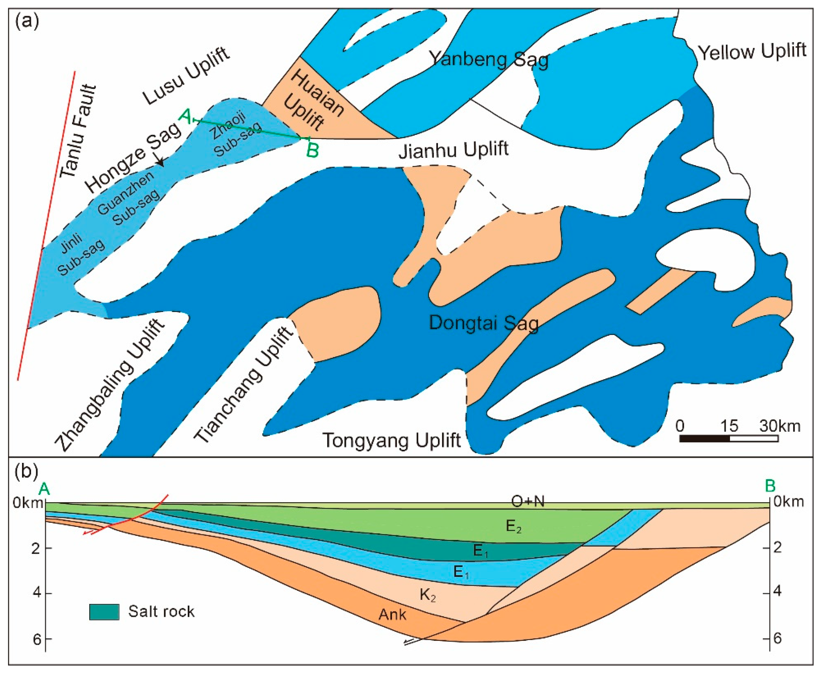
2.1. The Distribution of the Salt Rock

The Hongze Sag, located between the Sulu Uplift and the Jianhu Uplift, is bounded by the Tanlu Fault to the west and the Huaian Uplift to the east, and represents the westernmost sag in the Subei Basin [39]. The Hongze Sag extends along the northeast–southwest direction and is approximately 140 km in length and 20–25 km in width. From northeast to southwest, the Hongze Sag consists of the Zhaoji Sub-Sag, Guanzhen Sub-Sag, and Jinli Sub-Sag, with the depth of the sag gradually decreasing (Figure 1a) [40]. The Zhaoji Sub-Sag is a half-graben basin formed in the Mesozoic and Cenozoic. From north to south, it can be divided into three secondary tectonic units: the slope zone with thin and overlapping strata, the deep sag zone with the thickest strata, and the fault zone with steep and thick strata [41] (Figure 1b). The sag is primarily composed of the Upper Cretaceous Taizhou Formation, the Paleocene Funing Formation, the Eocene Dainan Formation, and the Sanduo Formation. The salt-bearing strata exist among the fourth member of the Funing Formation [42]. The fourth member of the Funing Formation in the Zhaoji Sub-Sag mainly consists of salt rock, thenardite, glauberite, anhydrite, calcite, dolomite interbedded with mudstone, calcareous mudstone, and gypsum mudstone. Among these, salt rock is the most widely distributed [43]. The Huaian gas storage site is located within the Zhaoji Sub-Sag. The salt rock is stably distributed in layers, with the burial depth and thickness gradually increasing from northeast to southwest. The salt layer is buried at a depth of 1000–2500 m, with a thickness of 37.5–169.5 m and an average thickness of 123.9 m [42]. The salt layer in the Huaian salt cavern gas storage area is mainly composed of salt rock, glauberite-bearing mudstone, and anhydrite-bearing mudstone [42,44].

2.2. The Shape of the Cavern
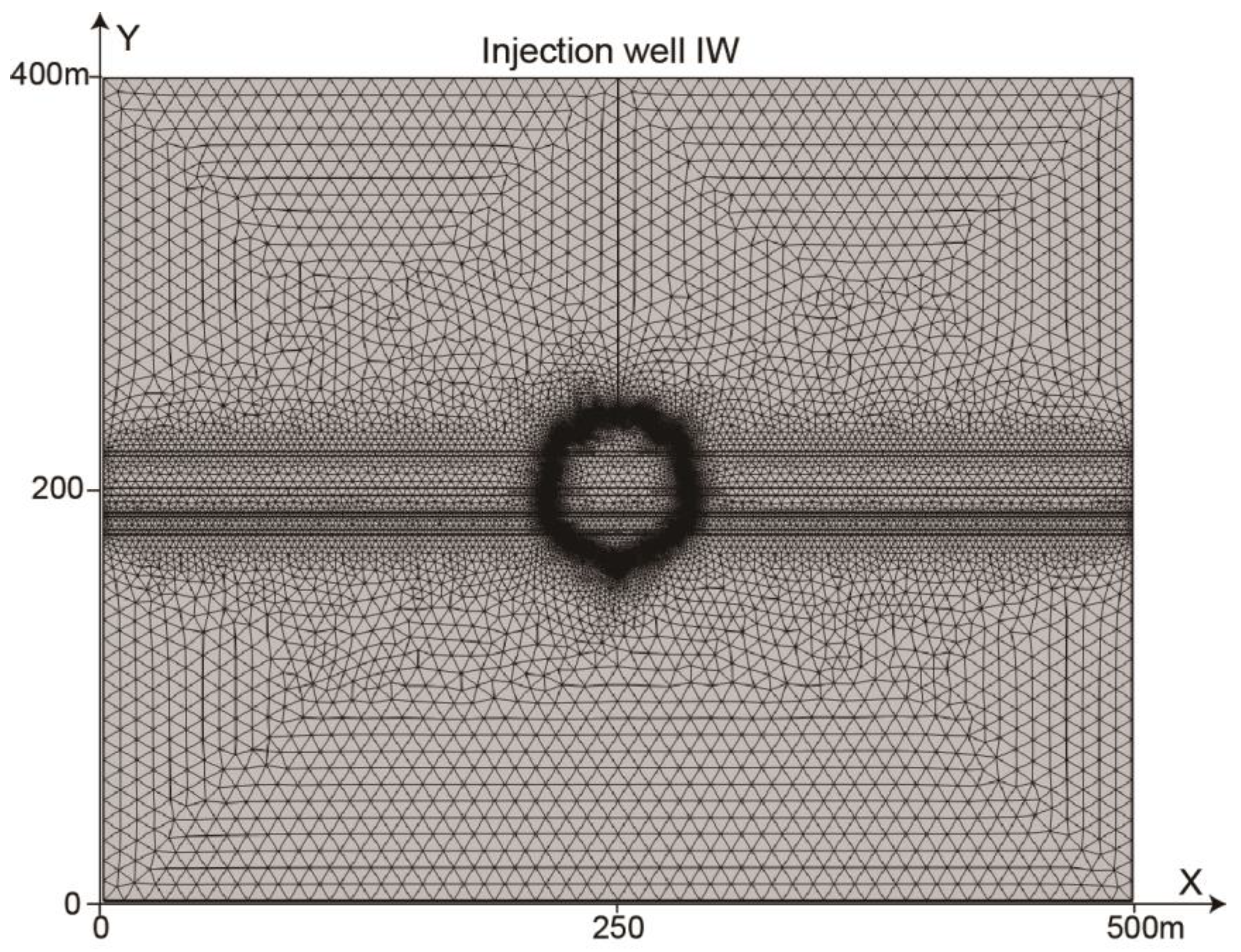
The shape of the salt cavern gas store is primarily influenced by the structural characteristics of salt layers, the distribution of salt layers, and the cavity-building techniques. Common shapes include ellipsoidal, spherical, pear-shaped, and egg-shaped caverns [45]. However, based on data from existing gas storage facilities, constructing regularly shaped salt caverns is highly challenging. The procedures for constructing salt caverns can be divided into five steps: site selection, drilling the well, solution mining, cavern enlargement, and casing and completion [15]. The Huaian salt cavern gas storage facility has been completed, and the actual shape of the salt cavern is a frustum shape with a conical bottom. The cavern has an absolute burial depth of 1493–1566 m, with a height of 73 m, and a maximum diameter of 80 m at a depth of 1537 m [44] (Figure 2a).

2.3. Physical Model

Based on the distribution characteristics of Huaian salt layers and the shape of the salt cavern, the salt layer with a roof burial depth of 1500 m is selected for this study. The simulation is conducted on a rectangular grid measuring 500 meters in the X direction and 400 meters in the Y direction. The salt cavern is modeled as a frustum shape with a conical bottom, with the bottom of the cavern located 163 m above the lower boundary of the model. Mudstone interlayers with thicknesses of 2.34 m, 1.91 m, 3.47 m, and 2.44 m exist at 177.74 m, 186.50 m, 196.90 m, and 215.89 m, respectively, above the lower boundary of the model (Figure 2b).

3. The Mathematical Model of CO2 Storage in Salt Caverns

3.1. Model Assumptions

The mathematical models should be based on the following basic assumptions: (1) The salt rock and mudstone interlayers are modeled as isotropic and continuous porous media. (2) CO2 exists only within the salt cavern in the supercritical phase. (3) The migration of CO2 in salt layers and mudstone interlayers follows Darcy’s law, with a consideration of the diffusion effect, the Klinkenberg effect, and gravity. (4) The deformation of the salt layers and mudstone interlayers complies with the small deformation assumption. (5) The temperature effects on CO2 transport and the deformation of salt layers and mudstone interlayers are considered.

3.2. Governing Model of Deformation

The deformation of the salt rock and mudstone is the sum of the strains induced by the gas pressure and reservoir temperature. The governing model of deformation is composed of three components: the constitutive equation, the equilibrium equations, and the geometric equations. Assuming the salt layers and mudstone interlayers are isotropic and the pores are fully saturated with gas, the elastoplastic constitutive equation considering the gas pressure and temperature is presented as follows [46,47]:
ε i j = 1 2 G σ i j 1 6 G 1 9 K σ h h δ i j + α p 3 K δ i j + α T T 3 δ i j
where ε i j is a component of the total strain tensor; G is the shear modulus, MPa; E is the elastic modulus, MPa; ν is the bulk Poisson ratio; σ 11 , σ 22 , and σ 33 denote the normal stresses along the three axial directions of the spatial coordinate system; K is the bulk volume modulus, MPa; K = E/(3 × (1 − 2ν)); δij is the Kronecker delta, which equals 1 for i = j and 0 for i ≠ j; α is the effective Biot coefficients; p is the gas pressure, MPa; and αT is the thermal expansion coefficient, K−1.
Under the assumption of small deformations, the equilibrium equations and the strain–displacement relations for salt or mudstone interlayers are, respectively, governed by the following two equations [48]:
σ i j , j + F i = 0
ε i j = 1 2 μ i , j + μ j , i
where μ i is the displacement along the i direction; σ i j is a component of the total stress tensor, MPa; and F i is the body force along the i direction, MPa, with i, j = x, y, z.
Combining Equations (1)–(3) yields the deformation equation for the gas-bearing salt rock and mudstone:
G μ i , j j + G 1 2 v μ j , j i K α T T , i α p , i + F i = 0

3.3. Gas Transport in Salt Rock and Mudstone Interlayer

Mudstone and salt rock are considered as porous media composed of pore and fracture systems, with consideration only given to the permeability of the fracture network. CO2 transport is treated as a continuous process combining diffusion and seepage, where CO2 diffuses from the salt cavern into the fractures and then exhibits seepage within them. The governing equation for CO2 transport in salt layers and mudstone interlayers considering the mass conservation law, Darcy’s law, the Klinkenberg effect, and the gravitational influence is as follows [49,50]:
Q g = m g t + ρ g v g D g m g
where m g is the mass storage of gas in salt layers and mudstone interlayers, kg/m3; ρ g is the gas density in salt layers and mudstone interlayers, kg/m3; v g is the gas seepage velocity vector, m/s; D g is the gas diffusion coefficient, m2/s; and Q g is the gas source item, kg/(m3 s).
The Peng–Robinson method is used to predict the density of supercritical CO2. The Peng–Robinson equation of state is represented as follows [51]:
p = R T m V m d a T m V m m V m + d + d ( m V m d )
where V m is the gas molar volume, m3/kg; R is the universal gas constant, 8.31 J/(mol K); and T is temperature, K.
d = 0.07780 R T c P c
a T = 0.45724 R 2 T c 2 α T P c
α T = 1 + m 1 T T c
where m is a function of the eccentric factor, m = 0.37464 + 1.54226 ω 0.26992 ω 2 . For CO2, ω = 0.225 , P c = 7.38 MPa, and T c = 304.1 K.
The mass storage of gas in salt layers and mudstone interlayers can be expressed as follows:
m g = φ ρ g = φ M g V m
where φ is the porosity of the salt rock and mudstone, %; M g is the molar mass of CO2, kg/mol.
The calculation formula for the seepage velocity of gas is
v g = k e μ p ρ g g h
where k e is the effective permeability, m2; μ is the dynamic viscosity coefficient, Pa s.

3.4. Governing Equation of Thermal Field

In the salt layers and mudstone interlayers, both the solid skeleton and the gas satisfy the energy conservation law. The energy conservation equations for the solid skeleton and the gas are derived as follows [52]:
t ρ c T S = λ s T + Q s
t ρ c T g + ν ρ c T g = λ g T + Q g
where ρ S is the density of the solid skeleton, kg/m3; c S and c g are the specific heat capacity of the solid skeleton and gas, respectively, J/(kg K); λ S and λ g are the heat conductivity of the solid skeleton and gas, respectively, W/(m K); and Q s and Q g are the heat source item of the solid skeleton and gas, respectively, W/m3.
Under the assumption of a thermal equilibrium between the solid skeleton and gas, and considering the deformation energy, the unified energy conservation equation is derived as follows [34]:
ρ c p e q T t λ e q T + ρ c p g μ T + 1 n T 0 γ ϵ v t = Q e q
where T 0 is the initial temperature, K; Q e q is the heat source item of porous media filled with gas, W/m3; Q e q = n Q s + 1 n Q g ; ρ c p e q and λ e q are the specific heat capacity and heat conductivity of porous media filled with gas, respectively, W/(m K); and ρ c p e q = n ρ c p s + 1 n ρ c p g and λ e q = n λ s + 1 n λ g .

3.5. Governing Equation of Porosity and Permeability

The relationship between the porosity and volume strain in the salt rock and mudstone can be derived as follows [53,54]:
φ = V P V = 1 1 φ 0 1 + ε 1 + V s V s 0
where φ 0 is the initial porosity of the salt rock and mudstone, %; ε is the volume strain of the salt rock and mudstone; ΔVs is the change in the solid skeleton volume, m3; and Vs0 is the initial volume of the solid skeleton, m3.
V s V s 0 = α K s p + α T T
where K s is the bulk modulus of the solid skeleton, MPa; ΔT is the change in temperature, K; and Δp is the change in pressure, MPa.
Considering the cubic law relating to permeability and porosity, the permeability of the salt rock and mudstone can be expressed as follows [55]:
k k 0 = φ φ 0 3
where k 0 is the initial permeability, m2.
The formula for the effective permeability of gas derived by L. J. Klinkenberg [54] is
k e = k 1 + b p
where b is the Klinkenberg factor, which is determined by the temperature, gas type, and the pore structure of the porous media, and can be expressed as follows [56]:
b = 16 c μ r π R T 2 M g
where c is a constant, typically taken as 0.9; r is the pore radius, r = k / φ , m.

3.6. The Coupling Model of the THM Fields

The coupling model of the THM fields during the process of CO2 storage in salt caverns is as follows:
(1)
The changes in the mechanical fields of the salt layers and mudstone interlayers affect their porosity and permeability, subsequently leading to the variations in the hydraulic field. Conversely, the alterations in the hydraulic field influence the CO2 seepage velocity, pore pressure, and effective stress within the salt layers and mudstone interlayers, thereby modifying the mechanical fields.
(2)
The variations in the thermal fields of the salt layers and mudstone interlayers induce changes in the thermal stress, which in turn cause the changes in the mechanical fields. Reciprocally, the changes in the mechanical fields impact the heat transfer and strain energy within the salt layers and mudstone interlayers, subsequently resulting in the variations in the thermal fields.
(3)
On the one hand, the changes in the hydraulic fields of the salt layers and mudstone interlayers affect the heat transfer and thermal conduction, thereby causing the variations in the thermal fields. On the other hand, the changes in the thermal fields influence the density of CO2, subsequently leading to the alterations in the hydraulic fields.

4. Numerical Parameter and Scheme

This study selects the Huaian salt cavern gas storage site as the research subject. CO2 is injected into the salt cavern through the IW injection well (with a wellbore diameter of 0.1 m) (Figure 3). After the CO2 pressure reaches the storage pressure, the injection well is sealed to simulate the CO2 flow behavior during the CO2 storage in the salt cavern. The COMSOL 6.2 multiphysics simulation software is employed to solve the mathematical model using the finite element method. Initially, the selected physical model of the salt cavern is divided into triangular meshes, and mesh refinement is applied to the boundaries of the salt cavern and the interfaces between the salt layers and mudstone interlayers (Figure 3). To quantify the changes in the CO2 pressure and the permeability around the salt cavern during the simulation period, four lines and two observation points are selected to obtain the CO2 pressure, permeability, and seepage velocity in the salt rock and mudstone interlayers. Among these, Line A and Line B represent mudstone interlayers, while Line C and Line D represent salt rock layers. Point a and b are located on Line A and Line C, respectively (Figure 2b).
The main parameters influencing the efficiency of the CO2 storage in salt caverns include the following: the volume of the salt cavern, the storage pressure, as well as the porosity, permeability, and mechanical properties (such as the elastic modulus, Poisson’s ratio, and compressive strength) of the salt rock and mudstone. Among these factors, the volume of the salt cavern and the storage pressure determine the CO2 storage capacity, while the permeability, porosity, and mechanical properties of the salt rock and mudstone affect the safety of the CO2 storage.
In this study, numerical simulations of the CO2 storage in the salt cavern are conducted under three different injection pressures: 20 MPa, 25 MPa, and 30 MPa. The simulation time intervals are set at 1, 5, 10, 20, 30, and 40 years. The initial condition is defined as the original pressure of the salt layer, while the inner boundary condition is set as the gas storage pressure of the salt cavern. Considering that the maximum radius of the salt cavern is significantly smaller than that of the salt layer, the outer boundary condition is treated as a constant pressure boundary. The key parameters used in the simulation (Table 1) are mainly sourced from relevant references [8,44,57].

5. The Results of Numerical Simulations

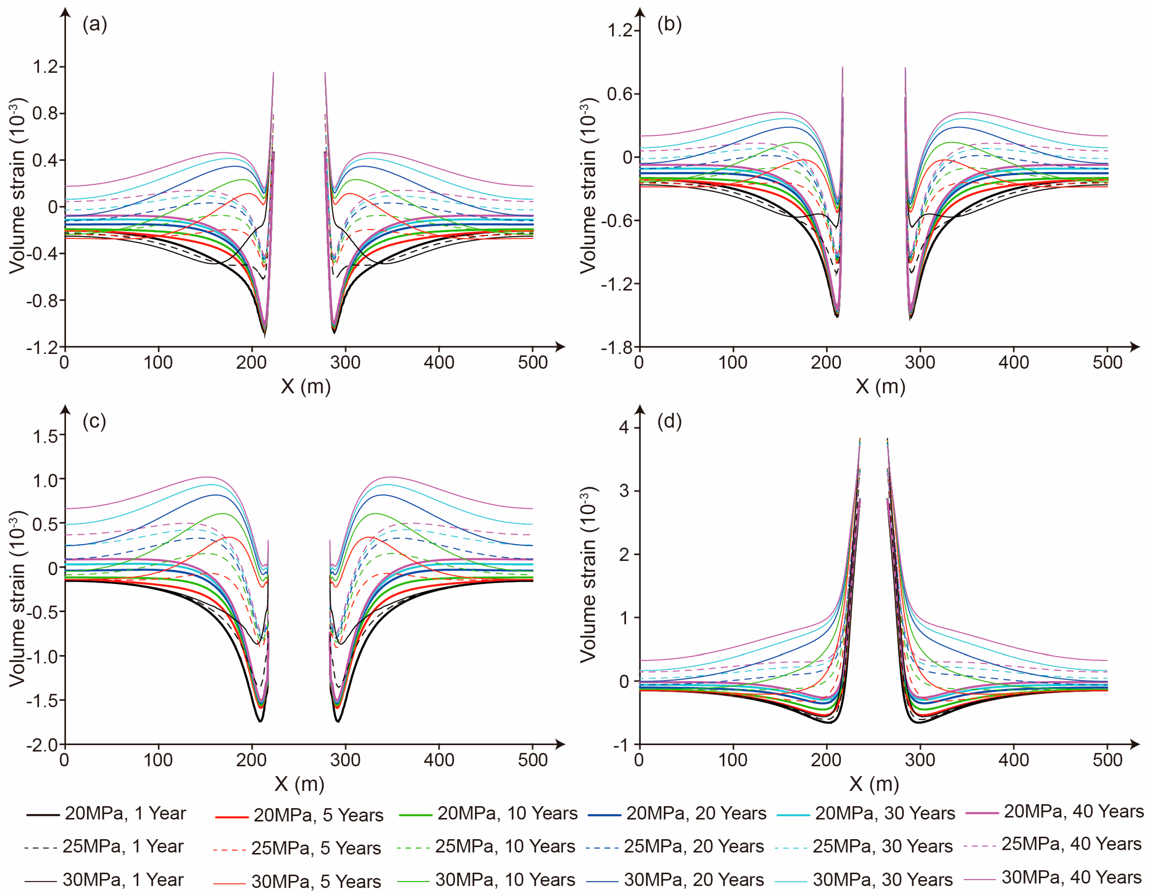
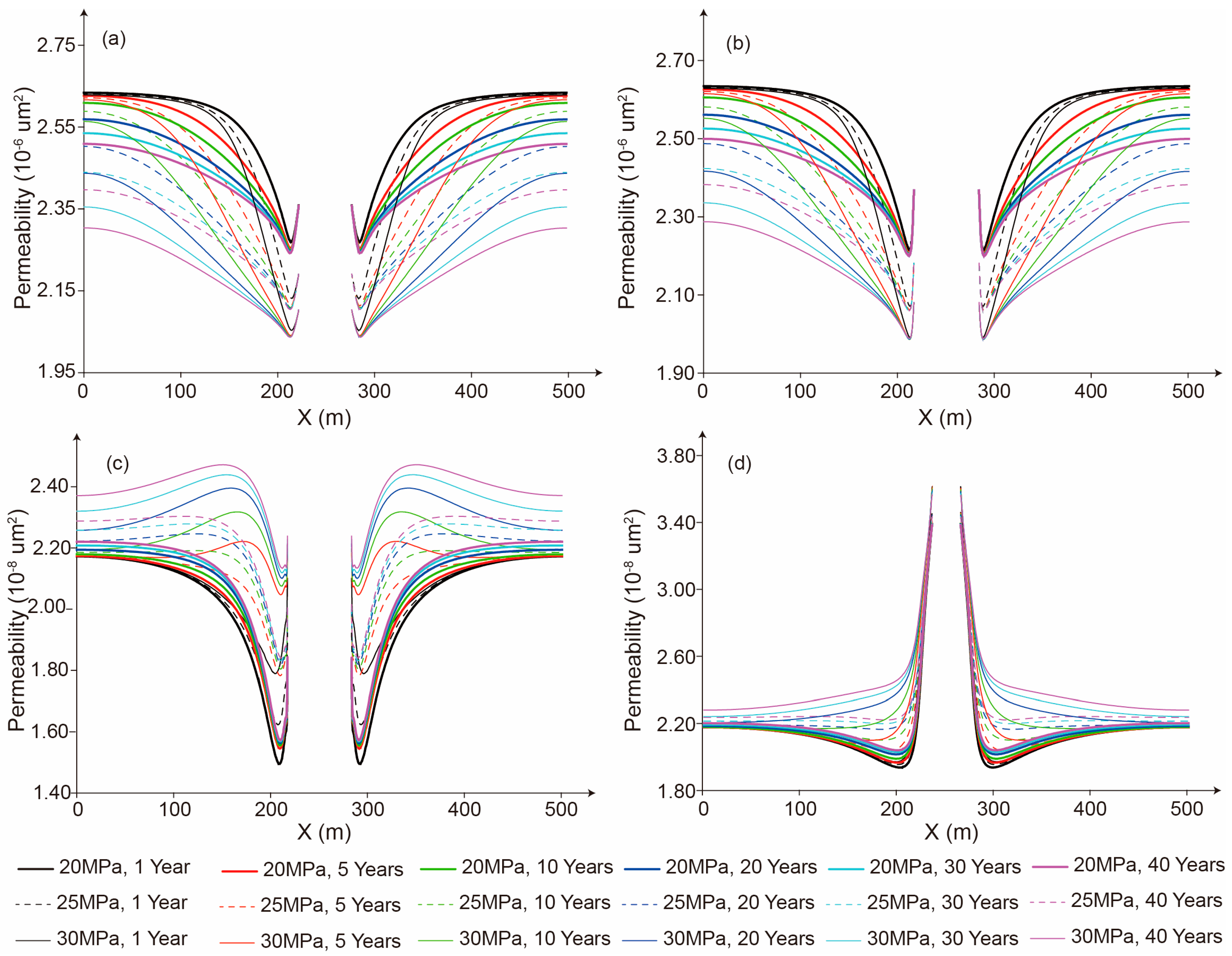
5.1. Strain Characteristics of the Salt Cavern and the Impact on Permeability

Effective stress is one of the primary factors influencing the permeability of porous media. During CO2 geological storage, the continuous pressure variations within the salt cavern induce the cavern deformation and effective stress changes. From the cavern edge to the simulation boundary, both the mudstone interlayers and salt layers exhibit similar deformation characteristics (Figure 4). The strain can be divided into three distinct segments: (1) Near the cavern edge, the compressive effect of the gas storage pressure results in a rapid reduction in the volume strain. (2) With the weakening of the gas storage pressure and the increase in the pore pressure, the volume strain gradually increases. (3) As both the compressive effect of the gas storage pressure and pore pressure diminish, the volume strain progressively decreases or stabilizes. For example, when the storage pressure is 30 MPa and the storage time is 40 years, the volume strains of Line A at 222 m (the cavern edge), 212 m, 170 m, and 0 m (the simulation boundary) are 1.2 × 10⁻³, 2 × 10⁻⁴, 5 × 10⁻⁴, and 2 × 10⁻⁴, respectively. The strain characteristics are governed by the storage pressure and time. With the increase in the storage time, the compression effect of the gas storage pressure gradually weakens, and the pore pressure gradually increases, which leads to the decrease in the volume strain near the salt cavern edge. For example, when the gas storage pressure is 25 MPa, volume strains of the mudstone at Point a and the salt rock at Point b increase from −4.48 × 10⁻⁴ and −4.44 × 10⁻⁴ at a storage time of 1a to −1.38 × 10⁻⁴ and 4.61 × 10⁻⁴ at a storage time of 40 years, respectively. With the increase in the storage pressure, the positive effect of the pore pressure outweighs the compression effect induced by the gas storage pressure, leading to a gradual elevation in the volume strain. For example, when the storage time is 20 years, the volume strains of the mudstone at Point a and the salt rock at Point b increase from −2.10 × 10⁻⁴ and −1.50 × 10⁻⁴ at a 20 MPa storage pressure to 2.86 × 10⁻⁴ and 7.88 × 10⁻⁴ at a 30 MPa storage pressure, respectively.
From the cavern edge to the simulation boundary, the permeability evolution in the salt layers and mudstone interlayers can also be divided into three segments: (1) Near the cavern edge, the increase in the effective stress induced by the gas storage pressure results in the closure of fractures/pores and a decrease in permeability. (2) With the elevation of the pore pressure, the reduced effective stress promotes fracture/pore dilation, gradually increasing permeability. (3) Approaching the simulation boundary, the declining pore pressure leads to a permeability reduction or stabilization. For instance, when the storage pressure is 30 MPa and the storage time is 5 years, the permeability of Line A at 222 m (the cavern edge), 212 m, 170 m, and 0 m (the simulation boundary) is 2.10 × 10⁻⁶ μm2, 2.04 × 10⁻⁶ μm2, 2.22 × 10⁻⁶ μm2, and 2.61 × 10⁻⁶ μm2, respectively. In addition to the effective stress, the storage time and pressure also affect the permeability of the salt rock and mudstone interlayers (Figure 5).

5.2. The Influence of the Mudstone Interlayer on Seepage Behavior

The pore pressures in both the salt layers and mudstone interlayers exhibit a gradual decline from the cavern edge to the simulation boundary (Figure 6 and Figure 7). However, due to the higher permeability of the mudstone interlayers compared to the salt layers, the pore pressure in the mudstone interlayers at an equivalent distance from the cavern edge is consistently greater than that in salt layers. Concurrently, the permeability of both the mudstone interlayers and salt layers initially decreases and subsequently increases with distance from the cavern edge. This is because the elastic modulus of the mudstone (10 GPa) is significantly larger than that of the salt rock (5.6 GPa), making the mudstone less susceptible to deformations under effective stress. Additionally, due to its relatively higher permeability, the impact of the pore pressure and gas storage pressure on the mudstone permeability is smaller. As a result, the permeability reduction near the salt cavern edge is less pronounced in mudstone interlayers compared to salt layers (Figure 5). The higher permeability and pore pressure in mudstone interlayers result in a significantly greater CO2 seepage velocity compared to the salt layers, showing orders of magnitude differences. For instance, at a storage pressure of 20 MPa and a storage time of 20 years, the CO2 seepage velocities reach 8.60 × 10⁻² m/year in the mudstone (Point a) and 1.10 × 10⁻³ m/year in salt rock (Point b). Notably, because CO2 migrates from mudstone interlayers into the salt layer, the flow distance of CO2 in salt layers near mudstone interlayers is greater than that in salt layers away from mudstone interlayers. For example, after 5 years of storage under 20 MPa, the pore pressure decreases from 20 MPa to 15.5 MPa over a distance of 128 m in Line C (near mudstone), compared to only 102 m in Line D (distant from mudstone). These observations indicate that mudstone interlayers serve as primary pathways for CO2 leakage and are detrimental to the long-term integrity of CO2 storage.

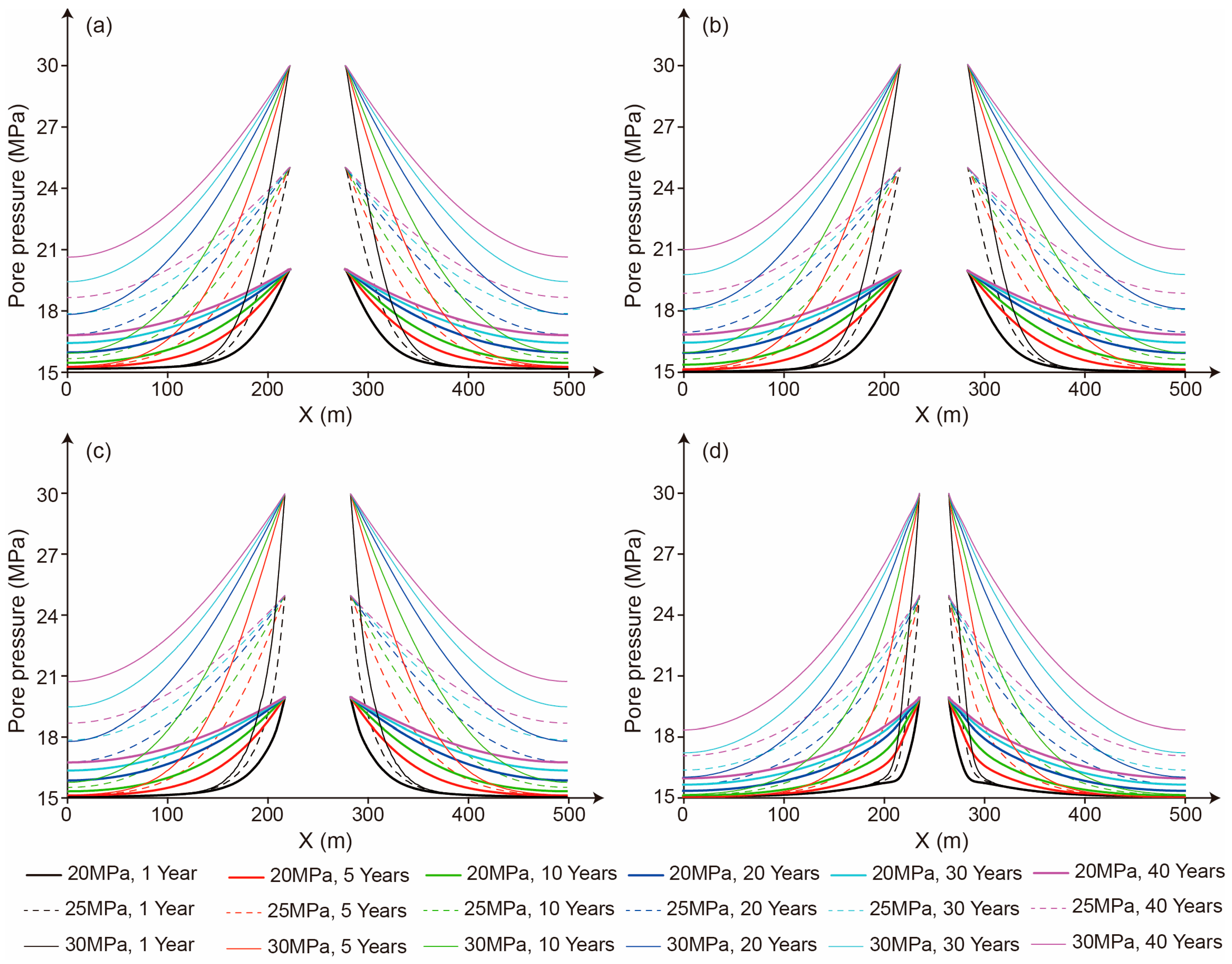
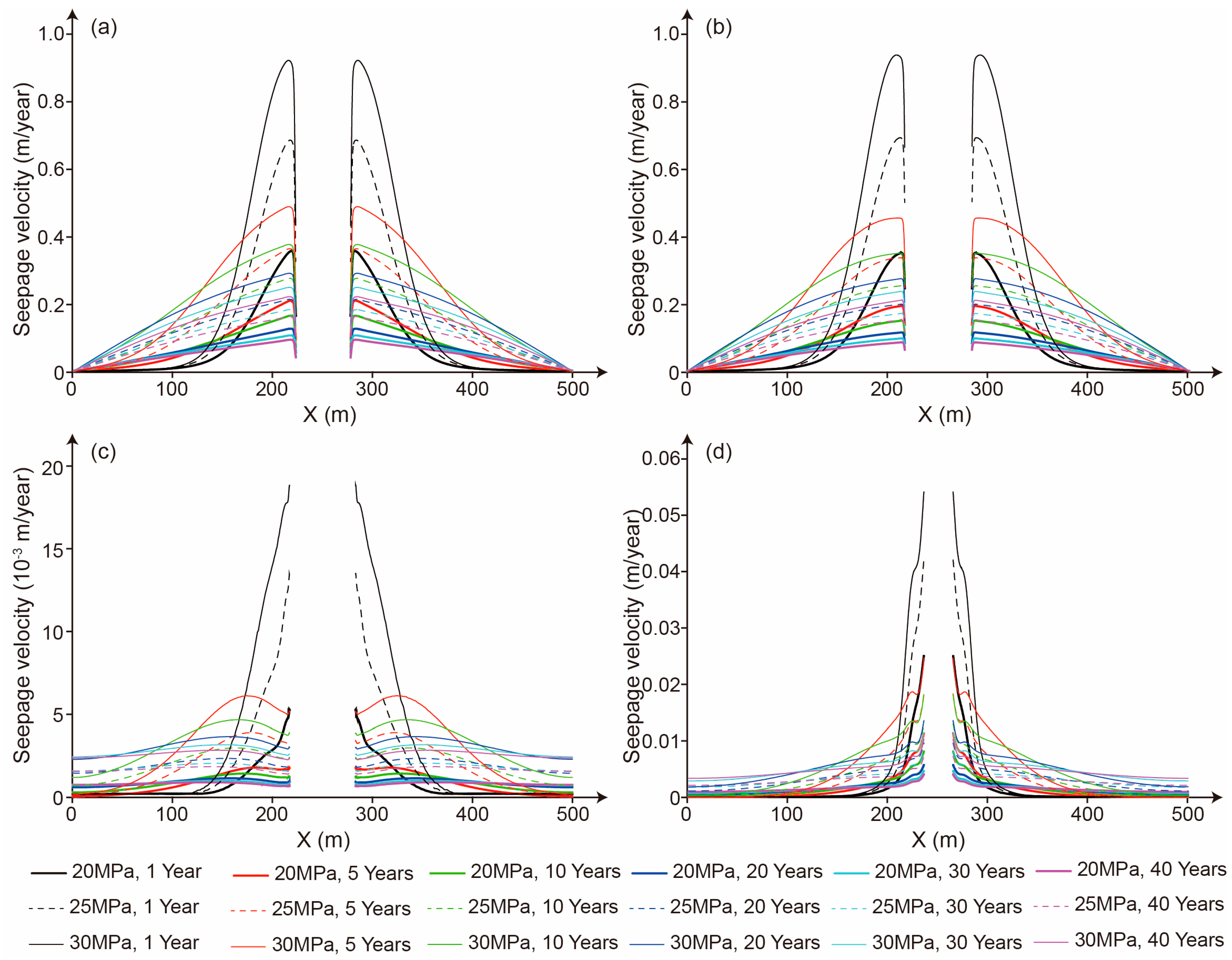
5.3. The Influence of Storage Time on the Seepage Character

The temporal variation in the pore pressure induces consequential changes in permeability. As the storage time increases, the pore pressure and permeability within the mudstone interlayer gradually decrease (Figure 5a,b). However, the variations in the permeability in salt layers are relatively complex. At the salt cavern edge, the magnitude of the permeability reduction caused by the compression from the storage gas pressure diminishes as the storage time increases. Near the simulation boundary, the impact of the storage time on salt permeability weakens, with permeability variations across different storage times becoming relatively minor and converging to similar values (Figure 5c,d). The pore pressures in the salt layer and mudstone interlayer both show a progressively increasing trend with extended storage time (Figure 7). Influenced by permeability and pore pressure, the CO2 seepage velocity changes differently over time. In the early stage of storage, the CO2 seepage velocity is higher at the salt cavern edge but rapidly decreases to zero due to the limited CO2-affected area. As the storage time increases, the permeability at the salt cavern edge decreases and the CO2 seepage velocity gradually declines. However, the seepage velocity decreases slowly due to the expansion of the CO2-affected area (Figure 8).

5.4. The Influence of Storage Pressure on Seepage Characteristics

As the storage pressure increases, the pore pressure in both the mudstone interlayers and salt layers exhibits a gradually consistent upward trend (Figure 7). However, the influence of the storage pressure on permeability differs significantly between the mudstone interlayers and salt rock. Specifically, the permeability in mudstone interlayers decreases with the increasing storage pressure (Figure 5a,b). For example, at a storage time of 20 years, the pore pressures of the mudstone at Point a are measured as 17.68 MPa, 20.59 MPa, and 23.61 MPa, with a corresponding permeability of 2.43 × 10⁻⁶ μm2, 2.29 × 10⁻⁶ μm2, and 2.19 × 10⁻⁶ μm2, respectively, under storage pressures of 20 MPa, 25 MPa, and 30 MPa. In contrast, the salt rock permeability shows an increasing trend with an elevated storage pressure (Figure 5c,d). For instance, when the storage time is 20 years and the storage pressures are 20 MPa, 25 MPa, and 30 MPa, the pore pressures of the salt rock at Point b are 17.82 MPa, 20.89 MPa, and 24.04 MPa, and the values of permeability are 2.10 × 10⁻⁸ μm2, 2.23 × 10⁻⁸ μm2, and 2.39 × 10⁻⁸ μm2, respectively. The seepage velocities in both mudstone interlayers and salt layers are jointly influenced by the permeability and pore pressure, exhibiting a gradual increase with the rise in storage pressure (Figure 8). This indicates that the positive effect of the increase in pore pressure in the mudstone interlayer outweighs the negative effect of the decrease in permeability. For example, when the storage time is 20 years and the storage pressures are 20 MPa, 25 MPa, and 30 MPa, the seepage velocities of the mudstone interlayer at Point a are 8.60 × 10⁻² m/year, 0.16 m/year, and 0.23 m/year, while the seepage velocities of the salt rock at Point b are 1.10 × 10⁻³ m/year, 2.31 × 10⁻³ m/year, and 3.62 × 10⁻³ m/year, respectively.

6. Study Limitations and Safety Suggestions

This study employs the numerical simulation method to investigate CO2 storage in salt caverns, and it presents three limitations: (1) There are bound to be differences in porosity and permeability among various mudstone interlayers. To facilitate the research, the same initial porosity and permeability were assigned to different mudstone interlayers. (2) This study focuses on the CO2 flow characteristics, neglecting the CO2 dissolved in pore water (solubility storage), the CO2 trapped by capillary forces (residual storage), and the CO2 that undergoes chemical reactions with minerals in mudstone (mineral storage). (3) This study does not consider the space occupied by the leaching residues piled up at the bottom of the salt caverns.
Unlike the cyclic injection–production operations employed in underground gas storage, CO2 injected into salt caverns is typically intended to be stored for decades or even permanently, imposing stricter requirements on cavern integrity. Based on the numerical simulation results of the CO2 migration characteristics in salt caverns, the following measures are proposed to improve CO2 storage safety:
(1)
The relatively high permeability of mudstone interlayers significantly increases the CO2 seepage velocity. Therefore, during the site selection and cavern construction processes for salt cavern storage reservoirs, mudstone interlayers should be avoided as much as possible. If it is unavoidable to encounter mudstone interlayers, locations with fewer mudstone interlayers and lower permeability should be selected. Meanwhile, an appropriate storage pressure and perfect monitoring methods can enhance the safety of CO2 storage in salt caverns with mudstone interlayers.
(2)
The CO2 seepage velocity is significantly influenced by the storage pressure. A higher storage pressure will notably expand the flow distance of CO2 around the salt cavern. Therefore, an appropriate storage pressure should be designed based on the number and thickness of mudstone interlayers, as well as the permeability and mechanical properties of both the mudstone interlayers and salt rock, to meet the requirements for the safety and economic viability of CO2 storage.
(3)
In contrast to the short-term cyclic injection–production approach employed in salt cavern gas storage, long-term CO2 storage within salt caverns results in a significant increase in the pore pressure within the salt and mudstone and an extended migration distance of CO2. Long-term or even permanent storage demands higher requirements on the safety of CO2 storage in salt caverns. Thereby, a comprehensive underground CO2 leakage monitoring system should be established to conduct the real-time monitoring of parameters such as the pore pressure, salt rock creep displacement, CO2 pressure, and temperature within the salt cavern to ensure the safety of CO2 storage in salt caverns.

7. Conclusions

This paper establishes and solves a THM coupled mathematical model for CO2 storage in Huaian salt caverns, aiming to analyze the flow characteristics of CO2 during its long-term storage in such caverns. The conclusions are as follows: (1) During the CO2 storage process, from the edge of the salt cavern to the simulation boundary, the volume strain and permeability exhibit a trend of rapid decline, followed by a gradual increase and an eventual stabilization or slight reduction. (2) The higher permeability of the mudstone interlayers results in a greater CO2 seepage velocity, pore pressure, and flow distance in the mudstone interlayers than those in the salt rock. (3) With the increase in the storage time, the permeability of the mudstone interlayers gradually decreases, while the permeability of salt layer shows a general tendency to increase. The CO2 seepage velocity at the cavern edge gradually decreases, but the rate of the decrease in the seepage velocity slows down when it is farther away from the cavern edge. (4) The increase in the storage pressure leads to a decrease in the permeability of mudstone interlayers and an increase in the permeability of salt layers. Simultaneously, as the storage pressure increases, the pore pressure and seepage velocity in both the salt layers and mudstone interlayers gradually rise. (5) It is advisable to avoid mudstone interlayers during site selection, select appropriate storage pressures, and enhance the development of underground CO2 leakage monitoring systems.

Supplementary Materials

The following supporting information can be downloaded at https://www.mdpi.com/article/10.3390/pr13051563/s1: Table S1: The comparison of various geological storage technology.

Author Contributions

Methodology, Y.Z.; formal analysis, J.K.; investigation, P.T.; writing—original draft preparation, B.C.; writing—review and editing, X.F.; funding acquisition, H.X. All authors have read and agreed to the published version of the manuscript.

Funding

This research was funded by the Science and Technology Project of Xuzhou (No. KC22345; No. KC23381), The General Research Project of Basic Science (Natural Science) Supported by Universities in Jiangsu Province (No. 23KJD560001), and the Major Scientific and Technological Innovation Projects in Jiangsu Province (No. BE2023855; No. BM2022037).

Data Availability Statement

The original contributions presented in this study are included in the article. Further inquiries can be directed to the corresponding author.

Conflicts of Interest

The authors declare no conflicts of interest.

References

  1. Yu, L.; Lu, B.; Sun, J.; Jiang, R.; Liu, Z.; Zhang, Z.; Naguib, H.M.; Hou, G. A novel approach to accelerate the carbonation of γ-C2S under atmospheric pressure: Increasing CO2 dissolution and promoting calcium ion leaching via triethanolamine. Constr. Build. Mater. 2024, 450, 138719. [Google Scholar] [CrossRef]
  2. Hou, G.; Yan, Z.; Sun, J.; Naguib, H.M.; Lu, B.; Zhang, Z. Microstructure and mechanical properties of CO2-cured steel slag brick in pilot-scale. Constr. Build. Mater. 2021, 271, 121581. [Google Scholar] [CrossRef]
  3. Cao, B.; Fu, X.; Kang, J.; Lu, J.; Tang, P.; Xu, H.; Huang, M. Mini-Review on Influence of CO2-Enhanced Coalbed Methane Recovery and CO2 Geological Storage on Physical Properties of Coal Reservoir. Energy Fuel 2024, 38, 23268–23280. [Google Scholar] [CrossRef]
  4. Jun, Y.S.; Zhang, L.; Min, Y.; Li, Q. Nanoscale chemical processes affecting storage capacities and seals during geologic CO2 sequestration. Acc. Chem. Res. 2017, 50, 1521–1529. [Google Scholar] [CrossRef]
  5. Lin, Z.; Kuang, Y.; Li, W.; Zheng, Y. Research status and prospects of CO2 geological sequestration technology from onshore to offshore: A review. Earth-Sci. Rev. 2024, 258, 104928. [Google Scholar] [CrossRef]
  6. Sampath, K.H.S.M.; Ranjith, P.G.; Perera, M.S.A. A Comprehensive Review of Structural Alterations in CO2-Interacted Coal: Insights into CO2 Sequestration in Coal. Energy Fuels 2020, 34, 13369–13383. [Google Scholar] [CrossRef]
  7. Yang, K.; Zhou, J.; Xian, X.; Zhang, C.; Gan, Q.; Dong, Z. Effect of supercritical CO2-water-shale interaction on mechanical properties of shale and its implication for carbon sequestration. Gas Sci. Eng. 2023, 111, 204930. [Google Scholar] [CrossRef]
  8. Zong, S.; Liu, S.Q.; Xu, H.; Wang, W.K.; Cao, B.; Huang, F.S. Numerical simulation of CO2 storage in bedded salt rock storage cavern in Subei basin. Coal Geol. Explor. 2023, 51, 27–36, (In Chinese with English abstract). [Google Scholar]
  9. Leiby, P.; Bowman, D. The Value of Expanding the U.S. Strategic Petroleum Reserve 1. ORNL/TM-2000/179; Oak Ridge National Laboratory: Oak Ridge, TN, USA, 2000. [Google Scholar]
  10. Davis, R.M. National Strategic Petroleum Reserve. Science 1981, 213, 618–622. [Google Scholar] [CrossRef]
  11. Langer, M. Use of solution-mined caverns in salt for oil and gas storage and toxic waste disposal in Germany. Eng. Geol. 1993, 35, 183–190. [Google Scholar] [CrossRef]
  12. Chen, J.S.; Li, J.J.; Jing, G.; Ao, H.B.; Liu, C.; Wang, Y.G.; Fu, Y.P. Research progress of geomechanical evaluation system used for Jintan salt cavern gas storage. Oil Gas Storage Transp. 2018, 37, 1088–1096, (In Chinese with English abstract). [Google Scholar]
  13. Yang, C.H.; Wang, G.B.; Shi, X.L.; Zhu, S.J.; Zheng, Z.Y.; Liu, W.; Fan, H.Y. Demands and challenges of large-scale salt cavern hydrogen storage in China. Rock Soil. Mech. 2024, 45, 1–19, (In Chinese with English abstract). [Google Scholar]
  14. Cheng, W.B.; Wang, K.F.; Fu, X.H.; He, P. Brief analysis of carbon dioxide storage in salt caverns. China Well Rock Salt 2023, 54, 16–18, (In Chinese with English abstract). [Google Scholar]
  15. Mwakipunda, G.C.; Mgimba, M.M.; Ngata, M.R.; Yu, L. Recent advances on carbon dioxide sequestration potentiality in salt caverns: A review. Int. J. Greenh. Gas Control 2024, 133, 104109. [Google Scholar] [CrossRef]
  16. Bachu, S.; Dusseault, M.B. Underground Injection of Carbon Dioxide in Salt Beds. In Developments in Water Science; Tsang, C., Apps, J.A., Eds.; Elsevier: Amsterdam, The Netherlands, 2005; Volume 52, pp. 637–648. [Google Scholar]
  17. Costa, Á.M.D.; Costa, P.; Miranda, A.C.O.; Goulart, M.B.R.; Bergsten, A.; Meneghini, J.R.; Nishimoto, K.; Assi, G.R.S.; Sampaio, C.M.P.; Ebecken, N.F.F. Well Design for the Construction and Operation of an Experimental Salt Cavern Built Offshore in Ultra-Deep Water for CCS in Brasil. In Proceedings of the 54th U.S. Rock Mechanics/Geomechanics Symposium, Golden, CO, USA, 28 June–1 July 2020. [Google Scholar]
  18. Zhou, B. The Jintan gas storage of the natural gas branch—Building an “underground granary” for the Yangtze river economic belt. Sinopec 2023, 11, 38. [Google Scholar]
  19. Ministry of Ecology and Environment. Annual Report on Carbon Dioxide Capture, Utilization and Storage (CCUS) in China (2024); Ministry of Ecology and Environment: Beijing, China, 2024. [Google Scholar]
  20. Ba, J.H.; Kang, Y.P.; Jiang, H.T.; Zhou, D.L.; Jiao, Y.J.; Li, R.M.; Ren, Z.X.; Qi, D.S.; Jing, G.; Yan, F.L. Present situation and prospect of the utilization of old cavity in domestic salt cavern gas storage. Petrochem. Ind. Appl. 2020, 39, 1–5, (In Chinese with English abstract). [Google Scholar]
  21. Zhang, X.; Liu, W.; Chen, J.; Jiang, D.; Fan, J.; Daemen, J.J.K.; Qiao, W. Large-scale CO2 disposal/storage in bedded rock salt caverns of China: An evaluation of safety and suitability. Energy 2022, 249, 123727. [Google Scholar] [CrossRef]
  22. Huang, X.; Xiong, J. Numerical simulation of gas leakage in bedded salt rock storage cavern. Procedia Eng. 2011, 12, 254–259. [Google Scholar] [CrossRef]
  23. Ge, X.; Huang, J.; Zhou, K.; Su, K.; Wang, W.; Li, Y.; Shi, X. Research of interlayer dip angle effect on stability of salt cavern energy and carbon storages in bedded salt rock. Geoenergy Sci. Eng. 2024, 243, 213291. [Google Scholar] [CrossRef]
  24. Chen, F.; Wang, Z.; Meng, X.; Shi, X.; Ma, H.; Yang, C.; Li, H. Inversion of creep parameters and their application in underground salt cavern energy storage systems for enhancing wind power integration. Int. J. Electr. Power 2024, 162, 110237. [Google Scholar] [CrossRef]
  25. Fourmeau, M.; Liu, W.; Li, Z.; Nelias, D.; Fan, J.; Tian, H.; Liu, W. Research status of creep–fatigue characteristics of salt rocks and stability of compressed air storage in salt caverns. Earth Energy Sci. 2025, 1, 98–116. [Google Scholar] [CrossRef]
  26. Zhang, G.; Li, Y.; Yang, C.; Daemen, J.J.K. Stability and tightness evaluation of bedded rock salt formations for underground gas/oil storage. Acta Geotech. 2014, 9, 161–179. [Google Scholar] [CrossRef]
  27. Zhang, G.; Liu, Y.; Wang, T.; Zhang, H.; Wang, Z.; Zhao, C.; Chen, X. Pillar stability of salt caverns used for gas storage considering sedimentary rhythm of the interlayers. J. Energy Storage 2021, 43, 103229. [Google Scholar] [CrossRef]
  28. Cyran, K. Insight into a shape of salt storage caverns. Arch. Min. Sci. 2020, 65, 363–398. [Google Scholar]
  29. Wang, T.; Yang, C.; Chen, J.; Daemen, J.J.K. Geomechanical investigation of roof failure of China’s first gas storage salt cavern. Eng. Geol. 2018, 243, 59–69. [Google Scholar] [CrossRef]
  30. Wang, T.; Yan, X.; Yang, H.; Yang, X.; Jiang, T.; Zhao, S. A new shape design method of salt cavern used as underground gas storage. Appl. Energ. 2013, 104, 50–61. [Google Scholar] [CrossRef]
  31. Liu, W.; Duan, X.; Li, Q.; Wan, J.; Zhang, X.; Fang, J.; Jiang, D.; Chen, J. Analysis of pressure interval/injection and production frequency on stability of large-scale supercritical CO2 storage in salt caverns. J. Clean. Prod. 2023, 433, 139731. [Google Scholar] [CrossRef]
  32. Pajonpai, N.; Bissen, R.; Pumjan, S.; Henk, A. Shape design and safety evaluation of salt caverns for CO2 storage in northeast Thailand. Int. J. Greenh. Gas Control 2022, 120, 103773. [Google Scholar] [CrossRef]
  33. Fan, J.; Chen, J.; Jiang, D.; Ren, S.; Wu, J. Fatigue properties of rock salt subjected to interval cyclic pressure. Int. J. Fatigue 2016, 90, 109–115. [Google Scholar] [CrossRef]
  34. Chen, W.Z.; Tan, X.J.; Wu, G.J.; Yang, J.P. Research in gas seepage law in laminated salt rock gas storage. Chin. J. Rock Mech. Eng. 2009, 28, 1297–1304, (In Chinese with English abstract). [Google Scholar]
  35. Xiong, J.; Huang, X.; Ma, H. Gas leakage mechanism in bedded salt rock storage cavern considering damaged interface. Petroleum 2015, 1, 366–372. [Google Scholar] [CrossRef]
  36. Soubeyran, A.; Rouabhi, A.; Coquelet, C. Thermodynamic analysis of carbon dioxide storage in salt caverns to improve the Power-to-Gas process. Appl. Energy 2019, 242, 1090–1107. [Google Scholar] [CrossRef]
  37. Liu, Y.F. Pillar Stability of Salt Caverns Used for Gas Storage Considering Sedimentary Rhythm of Interlayers. Master’s Thesis, China University of Mining and Technology, Xuzhou, China, 2022. (In Chinese with English abstract). [Google Scholar]
  38. Guria, C. Pressure- and temperature-dependent klinkenberg slippage effect in porous media to non-ideal gases. Geoenergy Sci. Eng. 2023, 224, 211629. [Google Scholar] [CrossRef]
  39. Zhang, T.; Zhang, S.Y. Oil and gas accumulation characteristics of nearshore subaqueous fan in Hongze Sag. Lithol. Reserv. 2011, 23, 56–59, (In Chinese with English abstract). [Google Scholar]
  40. Zhao, Y.P.; Zhang, P.; Zhu, B.; Wu, J.F.; Che, Z.G.; Feng, L.W.; Xu, Y.s. Water inrush cause and resource exploitation in a salt exploration well in the Zhaoji Sub-sag, Hongze Sag. J. Geol. 2024, 48, 100–106, (In Chinese with English abstract). [Google Scholar]
  41. Wang, W.F.; Zhang, M. Study on deep water resedimented origin of saline sediments of E1f4 in Zhaoji Sag, Hongze Depression, Northern Jiangsu basin. Acta Sedimentol. Sin. 2015, 33, 242–253, (In Chinese with English abstract). [Google Scholar]
  42. Qi, D.S.; Li, J.J.; Ba, J.H.; Wang, Y.G.; Ao, H.B.; Li, S.P.; Wang, W.Q. Design of solution mining technology for thick-interlayer salt beds in Huai’an salt cavern gas storage. Oil Gas Storage Transp. 2020, 39, 947–952, (In Chinese with English abstract). [Google Scholar]
  43. Zhang, M. Study on the Origin and Distribution of Saline Sediments of E1f4 in Zhaoji Sag, Hongze Depression, Northern Jiangsu Basin. Master’s Thesis, China University of Petroleum (East China), Qingdao, China, 2014. (In Chinese with English abstract). [Google Scholar]
  44. Zhao, Y.J.; Ma, J.W.; Zheng, Y.L.; Wang, Z.Y.; Zhang, H.B. Determination of operating pressure limit for injection-production cycle of salt-cavern gas storage in Huai’an City. Oil Gas Storage Transp. 2013, 32, 526–531, (In Chinese with English abstract). [Google Scholar]
  45. Wei, D.H. Engineering Technology of Cavity Making in Jintan Salt Caverns Underground Gas Storage. Master’s Thesis, China University of Petroleum (East China), Qingdao, China, 2008. (In Chinese with English abstract). [Google Scholar]
  46. Li, W.; Liu, J.; Zeng, J.; Leong, Y.; Elsworth, D.; Tian, J. A fully coupled multidomain and multiphysics model considering stimulation patterns and thermal effects for evaluation of coalbed methane (CBM) extraction. J. Petrol. Sci. Eng. 2022, 214, 110506. [Google Scholar] [CrossRef]
  47. Fang, H.; Sang, S.; Liu, S. Establishment of dynamic permeability model of coal reservoir and its numerical simulation during the CO2-ECBM process. J. Petrol. Sci. Eng. 2019, 179, 885–898. [Google Scholar] [CrossRef]
  48. Fan, Y.; Deng, C.; Zhang, X.; Li, F.; Wang, X.; Qiao, L. Numerical study of CO2-enhanced coalbed methane recovery. Int. J. Greenh. Gas Control 2018, 76, 12–23. [Google Scholar] [CrossRef]
  49. Gong, S.; Zhang, L.; Zhang, T.; He, W.; Hu, W.; Yin, H.; Ma, L.; Hong, X.; Zhang, W.; Zhang, B. Numerical simulation of CO2-ECBM for deep coal reservoir with strong stress sensitivity. Heliyon 2024, 10, e34818. [Google Scholar] [CrossRef] [PubMed]
  50. Wang, G.; Wang, K.; Jiang, Y.; Wang, S. Reservoir permeability evolution during the process of CO2 -enhanced coalbed methane recovery. Energies 2018, 11, 2996. [Google Scholar] [CrossRef]
  51. Peng, D.Y.; Robinson, D.B. New Two-Constant Equation of State. Ind. Eng. Chem. Fundam. 1976, 15, 3069–3078. [Google Scholar] [CrossRef]
  52. Tan, X.J.; Chen, W.J.; Yang, J.P.; Yang, C.H. Study of THM-damage coupling model of gas storage in salt rock with interlayer. Rock Soil. Mech. 2009, 30, 3633–3641, (In Chinese with English abstract). [Google Scholar]
  53. Kong, X.; Wang, E.; Liu, Q.; Li, Z.; Li, D.; Cao, Z.; Niu, Y. Dynamic permeability and porosity evolution of coal seam rich in CBM based on the flow-solid coupling theory. J. Nat. Gas Sci. Eng. 2017, 40, 61–71. [Google Scholar] [CrossRef]
  54. Liu, S.Q.; Fang, H.H.; Sang, S.X.; Wu, J.G.; Zhang, S.R.; Zhang, B. Numerical simulation study on coal seam CO2-ECBM based on multi-physics fields coupling solution. Coal Sci. Technol. 2019, 47, 51–59, (In Chinese with English abstract). [Google Scholar]
  55. Liu, Z.; Hu, Z.; Zhu, W.; Zhao, T.; Liu, S.; Guo, Z.; Sun, C.; Bai, G. Effect of coal permeability evolution on CO2 storage capacity under phase partial pressure in ScCO2-ECBM processes. Energy 2024, 297, 131298. [Google Scholar] [CrossRef]
  56. Klinkenberg, L. The Permeability of Porous Media To Liquids And Gases. Drill. Prod. Pract. 1941, 108, 200–213. [Google Scholar] [CrossRef]
  57. Yang, S.Y. Experimental Study on Isobaric Specific Heat Capacity and Density of Carbon Dioxide Under Supercritical and Subcritical Pressure. Master’s Thesis, Dalian University of Technology, Dalian, China, 2020. [Google Scholar]
Figure 1. (a) A simplified tectonic sketch map of the Subei Basin; (b) a geological cross-section across the Zhaoji Sub-Sag, modified from Zhang [43].
Processes 13 01563 g001
Figure 2. (a) The shape of the Huaian salt cavern gas storage facility. (b) The physical model of the salt cavern in this study.
Processes 13 01563 g002
Figure 3. Mesh geometry for salt cavern.
Processes 13 01563 g003
Figure 4. Volume strain of mudstone interlayers Line A (a) and Line B (b), and salt layers Line C (c) and Line D (d) under storage pressures of 20 MPa, 25 MPa, and 30 MPa.
Processes 13 01563 g004
Figure 5. Permeability of mudstone interlayers Line A (a) and Line B (b), and salt layers Line C (c) and Line D (d) under storage pressures of 20 MPa, 25 MPa, and 30 MPa.
Processes 13 01563 g005
Figure 6. The distribution of the pore pressure under storage pressures of 20 MPa.
Processes 13 01563 g006
Figure 7. Pore pressure of mudstone interlayers Line A (a) and Line B (b), and salt layers Line C (c) and Line D (d) under storage pressures of 20 MPa, 25 MPa, and 30 MPa.
Processes 13 01563 g007
Figure 8. Seepage velocities of mudstone interlayers Line A (a) and Line B (b), and salt layers Line C (c) and Line D (d) under storage pressures of 20 MPa, 25 MPa, and 30 MPa.
Processes 13 01563 g008
Table 1. Key parameters for numerical simulation.
Parameter (Unit)Value
Overburden pressure (MPa)15
Initial reservoir temperature (K)338.15
Initial reservoir pressure (MPa)12
Initial porosity of salt rock (%)1
Initial porosity of mudstone (%)6
Initial permeability of salt rock (10−6 μm2)1 × 10⁻³
Initial permeability of mudstone (10−6 μm2)1
CO2 diffusion coefficient of mudstone (10−12 m2/s)0.5
CO2 diffusion coefficient of salt rock (10−12 m2/s)0.2
Elastic modulus of salt rock (GPa)5.16
Elastic modulus of mudstone (GPa)10
Heat conductivity of salt rock (W/(m K))2.5
Heat conductivity of mudstone (W/(m K))2.7
Specific heat capacity of salt rock (J/(kg K))837
Specific heat capacity of mudstone (J/(kg K))850
Permeability of the interfaces between salt rock and mudstone (10−6 μm2)1 × 10⁻²
CO2 heat conductivity (W/(m K))0.1
CO2 specific heat capacity (J/(kg K))10,000
Temperature of injection gas (K)318.15
Disclaimer/Publisher’s Note: The statements, opinions and data contained in all publications are solely those of the individual author(s) and contributor(s) and not of MDPI and/or the editor(s). MDPI and/or the editor(s) disclaim responsibility for any injury to people or property resulting from any ideas, methods, instructions or products referred to in the content.

