Abstract
To address roof overhang hazards (e.g., rock bursts and gas accumulation) in high-gas coal mines, this study proposes a static stress intervention method for controlled directional roof collapse. Using the 150110 fully mechanized face at Yiyuan Coal Mine as a case study, we investigate the mechanical mechanism of static stress intervention-induced roof collapse through theoretical modeling and FLAC3D simulations in the absence of pre-cracks. The study reveals that advanced boreholes filled with static expansion agents generate stress concentration zones along the drilling array. When superimposed with mining-induced stresses, this configuration induces tensile failure preferentially at borehole locations, thereby achieving controlled directional roof collapse. Theoretical calculations indicate that roof fracturing occurs at predetermined locations when expansion pressure reaches ≥9.11 MPa. FLAC3D simulations analyzed stress redistribution and plastic zone evolution under combined static and mining-induced stresses, demonstrating the method’s efficacy in optimizing roadway stability. Field trials implement spaced boreholes (65 mm diameter, 16 m depth, 1 m spacing) with alternating expansion agent charging, achieving a 6 m reduction in roof collapse intervals, effectively mitigating overhang hazards. Results confirm that static stress intervention reshapes the roof stress field, inducing tensile failure along predetermined paths without relying on pre-cracks. The findings provide theoretical and technical insights for roof stability control in high-gas coal mines.
1. Introduction
In underground coal mines, the timing and spatial distribution of roof collapse in fully mechanized mining faces directly influence the stability of the mining site and overall mining efficiency. However, due to the influence of complex geological conditions, the roof often forms a large-span unsupported roof due to excessive exposure, further triggering disasters such as rock burst and gas accumulation, which severely affect coal mine safety production. To address this challenge, researchers have proposed techniques such as dense drilling roof cutting [1,2], blasting pre-cracking [3,4,5], hydraulic fracturing [6,7,8], and mechanical fracturing [9] for roof pressure relief. However, each of these techniques has limitations. Traditional drilling roof cutting requires densely spaced boreholes, which is expensive and leads to uncontrollable disturbance ranges. Explosive blasting, although effective in regulating roof pressure, poses significant safety risks in high-gas mines and is therefore limited in application. Hydraulic fracturing equipment is precise, but crack propagation is constrained by the continuity of the rock mass. Mechanical fracturing incurs high costs and poses potential air leakage risks [10].
In recent years, static stress intervention technology has gained attention due to its mild reaction characteristics and operational safety. Li et al. [11] determined the optimal composition ratio of the breaking agent through experimental analysis, providing strong support for roof cutting and pressure relief. Huang [12], Huang et al. [13], and others used the expansion pressure of static expansion agents to pre-crack the roof by adjusting the water-to-cement ratio. Researchers such as Hao et al. [14,15,16,17] further verified its engineering applicability. Compared to traditional methods, static expansion agents are ordinary building materials that do not require special approval. Additionally, the process is controllable, avoiding the risk of explosive blasting. However, existing research primarily focuses on pre-crack-guided collapse, with little research on the collaborative effect of static and mining-induced stresses in the roof cutting mechanism.
Numerical simulation, as an effective tool for simulating mining processes, has gradually become an effective means of solving coal mining problems. For example, Tien Trung Vu et al. [18] used UDEC software to simulate the mining process of the 11th coal seam in the Nuibao coal mine in Vietnam, analyzed the displacement zone of the surrounding rock, and determined the affected area on the terrain surface; Dmytro Babets et al. [19] used RS3 and RS2 FEM simulation software to establish a three-dimensional model to analyze the stress–strain distribution of surrounding rock and study the deformation of tunnels under different parameter combinations. Li et al. [20] used FLAC3D software to simulate different fracturing schemes for key layers and analyzed the stress distribution pattern. Li et al. [21] demonstrated through comparative analysis of strain and deflection values obtained from load tests on a PCB bridge that finite element analysis can be effectively employed to validate engineering applications.
To address the problem of difficult roof collapse at the end of the fully mechanized mining face, the 150110 working face at Yiyuan Coal Mine is used as the engineering background. We propose a novel method to collaboratively utilize static and mining-induced stresses for roof cutting. Through theoretical modeling, the reshaping effect of static stress intervention on the roof stress field is analyzed. Combined with numerical simulations and field tests, the mechanical mechanism of collaborative stress driving directional roof collapse without pre-cracks is revealed. This study breaks through the traditional reliance on pre-cracks in roof-cutting technology, providing a new theoretical foundation and technical pathway for precise control of the roof in mining areas.
2. Project Overview
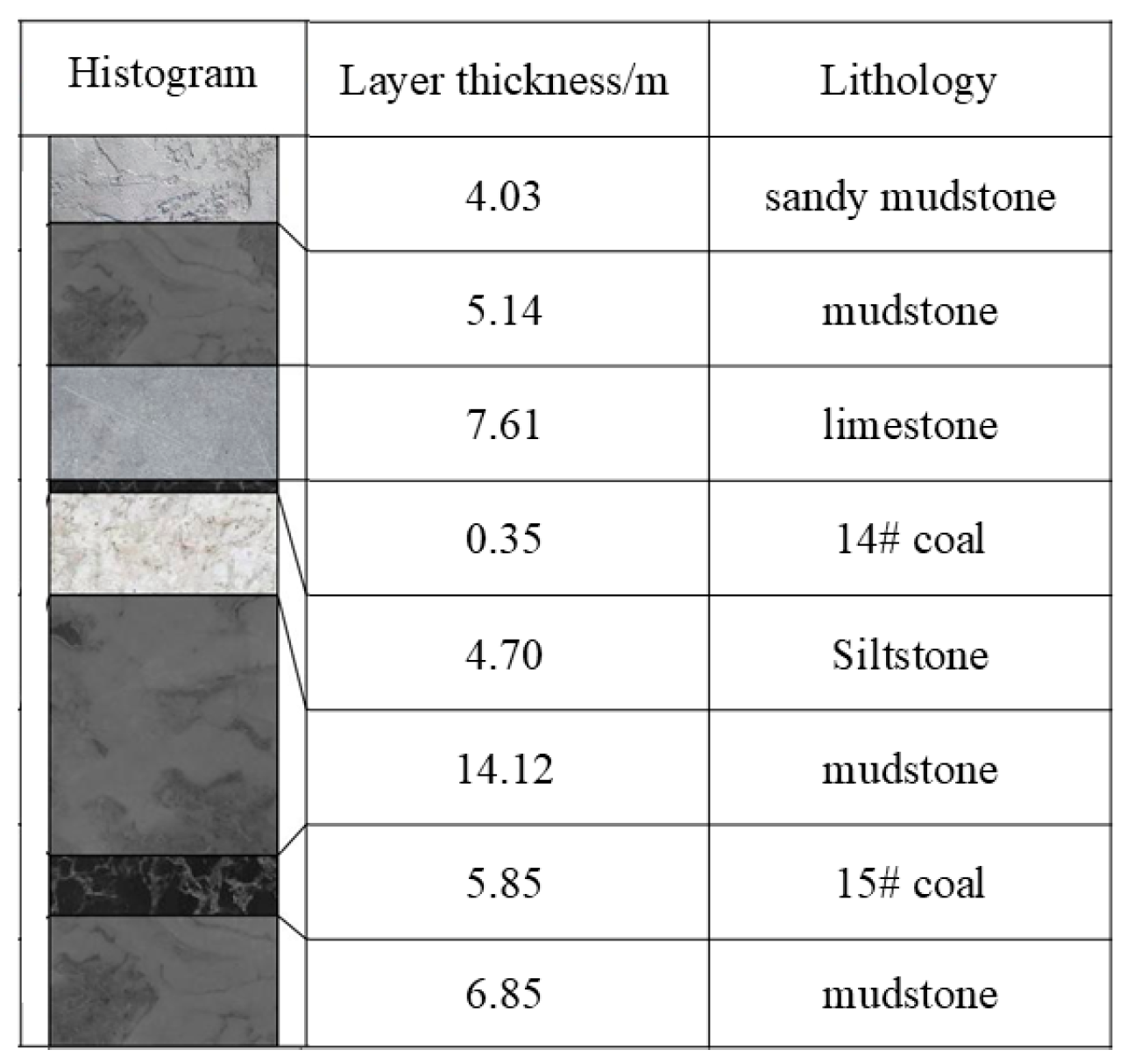
Jinneng Holding Group and Shun Yiyuan Coal Industry Co., Ltd. (referred to as “Yiyuan Coal Industry”) has a designed production capacity of 1.8 million tons per year. It is a high-gas mine, mining the No. 15 coal seam with an average seam thickness of 5.85 m, an average dip angle of 5°, and using the fully mechanized mining method for roof cutting and pressure relief. Based on the mining pressure data from the adjacent working faces, the initial collapse step distance for the immediate roof is 9.2 m, the first pressure step distance for the old roof is 32.2 m, and the periodic pressure step distance is 15 m. The roof and floor lithology mainly consist of mudstone, sandstone, and limestone. Figure 1 illustrates the stratigraphic column.
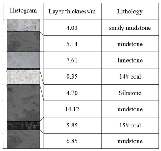
Figure 1.
Comprehensive stratigraphic histogram.
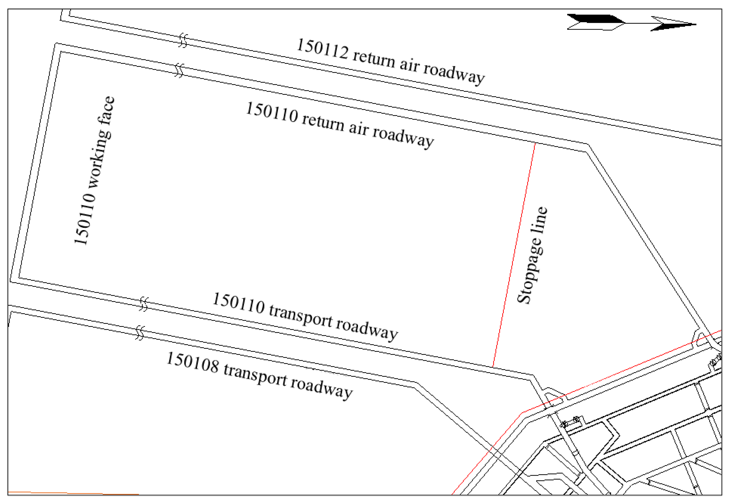
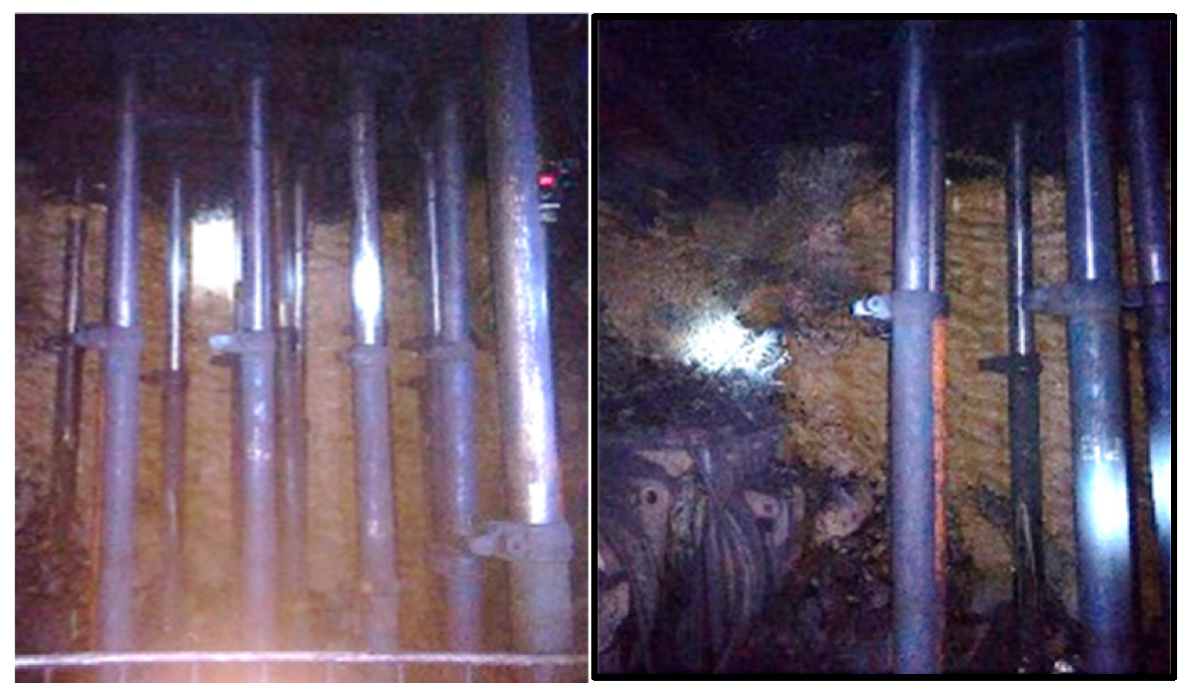
According to the mining sequence plan, the 150108 working face is the continuation of the 150110 working face, with a pillar width of 30 m. The relative position relationship is shown in Figure 2. Affected by the mining activities of the 150110 working face, the mining pressure in the transportation roadway of the 150108 working face is significant, and the significant surrounding rock deformation, requiring the expansion and repair of secondary support. At the same time, during the advancement of the 150110 working face, untimely roof collapse caused a large area of roof hanging at the end. To prevent the accumulation of corner gas and air leakage in the mined-out area, frequent construction of gob bag isolation walls at the working face end is necessary. The actual site conditions are shown in Figure 3. The large deformation of the surrounding rock and large-area roof hanging in the roadway pose certain safety risks to production operations, seriously affecting production progress and increasing labor and material input.
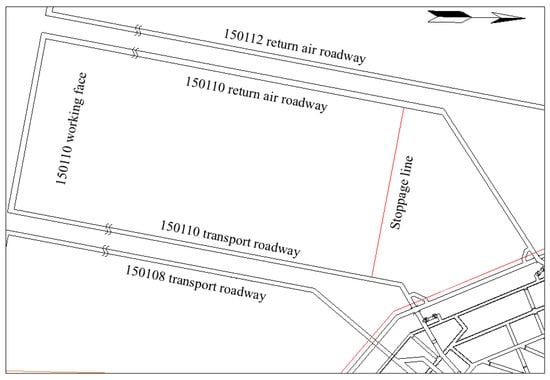
Figure 2.
150110 working face mining layout plan.

Figure 3.
Construction of gangue bag separation wall.
3. Mechanism of Static Stress Intervention in Roof Cutting
During the roof cutting and pressure relief process, if the roof rock mass has a free surface and the stress inside the hole reaches or exceeds its tensile strength, cracks will form; If the rock mass has no free surface and is under triaxial compression inside the hole, even if the expansion stress reaches the tensile strength of the rock, it will only change the stress state of the surrounding rock, thus achieving static stress intervention.
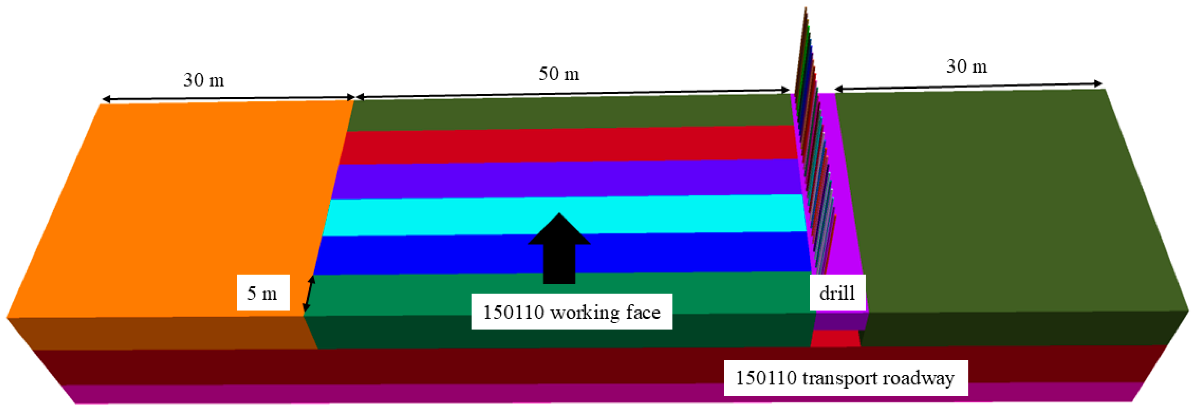
The principle of collaborative roof cutting between static stress and mining-induced stress is as follows: In the advanced working face, boreholes are drilled in the roof of the recovery roadway. Static expansion agents are filled into the holes, and the hydration reaction of the expansive agents generates expansion pressure that acts on the hole wall, creating a high-pressure state inside the hole and forming stress concentration zones along the borehole line. When the working face advances to the static stress intervention position, under the combined effect of mining-induced stress, the stress concentration zone is induced to become the location of roof fracture, causing the roof of the mining area to collapse along the borehole line in a timely manner. This achieves the engineering goal of roof cutting and pressure relief while optimizing the stress environment around the roadway. The 3D schematic diagram is shown in Figure 4.
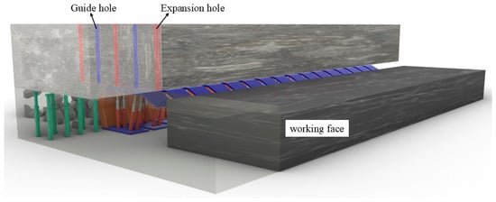
Figure 4.
Static stress intervention structure model diagram.
As the working face advances, the roof loses the support of the coal seam, and the collapsed gangue cannot provide timely support for the roof, causing the roof at the end of the working face to form a cantilever beam structure. Without manual control of the roof, the roof fractures and collapses when it reaches the critical bending moment. Due to the overhanging roof structure, the upper section is subjected to tensile stress, while the lower section experiences compressive stress. Since the tensile strength of the rock is much lower than its compressive strength, the failure first occurs on the upper surface of the roof. If pressure is applied through drilling, causing the stress at the borehole location to reach the ultimate tensile strength in advance, it is possible to intervene in the location of the roof collapse.
The constructed stress intervention mechanical model is shown in Figure 5.
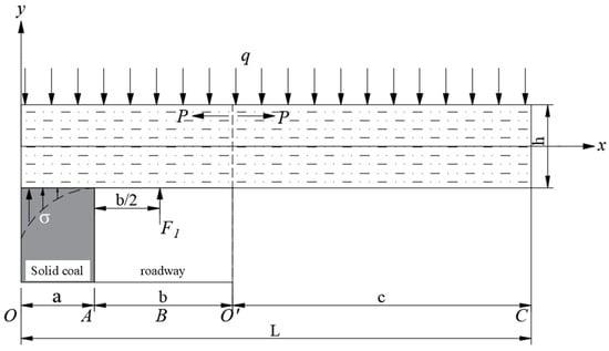
Figure 5.
Stress intervention mechanics model.
In the figure, σ represents the support force provided by the coal body in the plastic state of the solid coal pillar to the roof rock layers, in MPa; F1 represents the support force provided by the roadway support to the roof rock layers, in kN; q represents the average load of the immediate roof and the overlying rock layers, in kN/m; a represents the width at which the solid coal enters the plastic state, in meters; b represents the width of the roadway, in meters; L represents the overhang length of the immediate roof, in meters, i.e., the periodic pressure step distance of the immediate roof; h represents the thickness of the immediate roof, in meters.
When the roof fractures at point O, the width of the ultimate equilibrium zone inside the solid coal can be calculated using the following formula [22]:
In the equation, m represents the mining thickness of the coal seam, in meters; ξ is the triaxial stress coefficient, ξ = (1 + sin φ)/(1 − sin φ); φ is the internal friction angle of the coal body, in degrees; c is the cohesion of the coal body, in MPa; K is the stress concentration coefficient; γ is the average unit weight of the overlying rock layers, in kN/m3; H is the burial depth of the roadway, in meters; Px is the support resistance of the coal pillar, in MPa.
The support force of the coal body in the plastic state on the roof can be calculated using the following formula [23]:
According to the principles of material mechanics, without applying stress intervention (p), the cantilever beam will fracture at point O, and the ultimate bending moment at the point of fracture is
The maximum stress is
In the equation: σmax is the maximum stress, in KPa; Mmax is the maximum bending moment, in kN·m; Iz is the moment of inertia of the section, in m4.
If the unit width of the beam is taken, the moment of inertia of the section is
In the equation: h is the thickness of the immediate roof, in meters.
At the upper surface (z = h/2), the ultimate tensile stress at point O is:
The advanced working face drills a hole at position O′ in the roof and fills it with static expansion agents, forming continuous expansion pressure along a specific direction. The expansion force is symmetrically distributed within the hole, and the resulting bending moments cancel each other out. Stress is formed radially within the borehole, and the expansion pressure is assumed to be p.
When no expansion force is applied, the stress at point O′ is
After applying the expansion force, the total stress at point O′ is
When the total stress at point O′ reaches the ultimate tensile strength faster than at the fixed end, it causes the roof to collapse at the borehole location in advance. Therefore, the critical expansion force p must satisfy the following equation, i.e.:
Based on the actual geological conditions of the 150110 transportation roadway, the required parameters in the formula are assigned as follows: b = 5.5 m, Px = 0.153 MPa, φ = 30°, c = 1 MPa, m = 2.8 m, F1 = 200 kN, H = 300 m, K = 3, L = 15 m, γ = 25 kN/m3, and the basic roof load q = γH. Substituting into Equations (1), (2), and (9), the results are a = 6.78 m, σ = 2.77 MPa, and the force required to cause the roof rock layer to collapse at the specified location O′ is: p ≥ 9.11 MPa. The existing static expansion agent can meet the requirement of applying 9.11 MPa of expansion pressure inside the borehole.
In summary, by applying the expansion force, the roof is induced to reach the tensile strength limit at the borehole location first. After the working face recovers, under the combined effect of stress intervention and mining-induced stress, the roof is driven to initiate tensile failure along the borehole line, achieving the goal of roof cutting. Theoretical calculations show that, for the 150110 transportation roadway, when the expansion pressure exceeds 9.11 MPa, the roof will initiate tensile failure at the borehole location first, intentionally shifting the collapse location.
4. Analysis of Roof–Rock Pressure Under Static Stress Intervention
4.1. Numerical Simulation Model
Based on the actual geological conditions of the 150110 transportation roadway at Yiyuan Coal Industry, a FLAC3D numerical model is established to analyze the influence of static stress intervention on roof–rock pressure of the working face. The dimensions of the numerical model are 115 m × 30 m × 42 m (X × Y × Z), and the excavation size of the roadway is 5 m × 30 m × 3.3 m. The model’s perimeter and bottom are displacement-constrained, with fixed boundaries. The 150110 working face is buried at a depth of 300 m, and a vertical stress of 7.5 MPa is applied at the top of the model to simulate the pressure from the overlying rock layers, thirty-meter coal pillars are retained on both sides to mitigate boundary effects using the Mohr–Coulomb constitutive model. The model comprises 1,146,539 grids and 194,948 nodes. A gradient meshing strategy is adopted, where tetrahedral meshes are employed to locally refine critical research areas such as roadways and boreholes, achieving a continuous transition in mesh density from dense to sparse through a progressive gradient approach. The numerical model is shown in Figure 6, and the mechanical parameters of each rock layer are presented in Table 1.
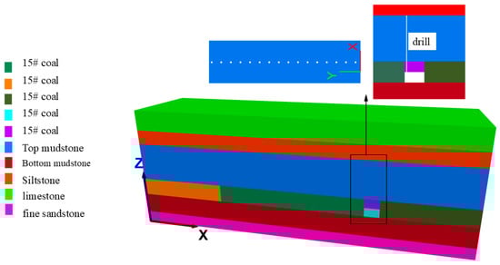
Figure 6.
Schematic diagram of the model.

Table 1.
Mechanical parameters of rock layer.
The borehole diameter is 65 mm, the height is 16 m, and the spacing is 1 m, arranged vertically to the roof. The radial expansion pressure inside the borehole is set to 30 MPa [12,13]. The borehole is located 800 mm from the coal pillar and arranged in a series along the tunnel direction, with expansion pressure applied to every other borehole. A stepwise excavation method is adopted, with an excavation step of 5 m. Excavation is carried out sixtimes, with a total excavation length of 30 m along the tunnel direction. The excavation plan is shown in Figure 7.
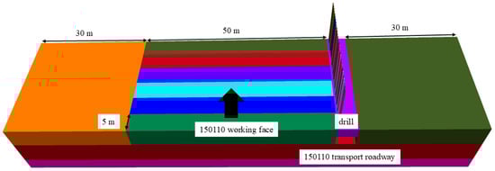
Figure 7.
Excavation plan.
4.2. Roof Mining Pressure Distribution Pattern
After the calculations, analyze the failure characteristics of the roadway roof on sections A-A and B-B during excavation advancement to verify the roof cutting effect under the combined effects of static stress and mining-induced dynamic stresses.
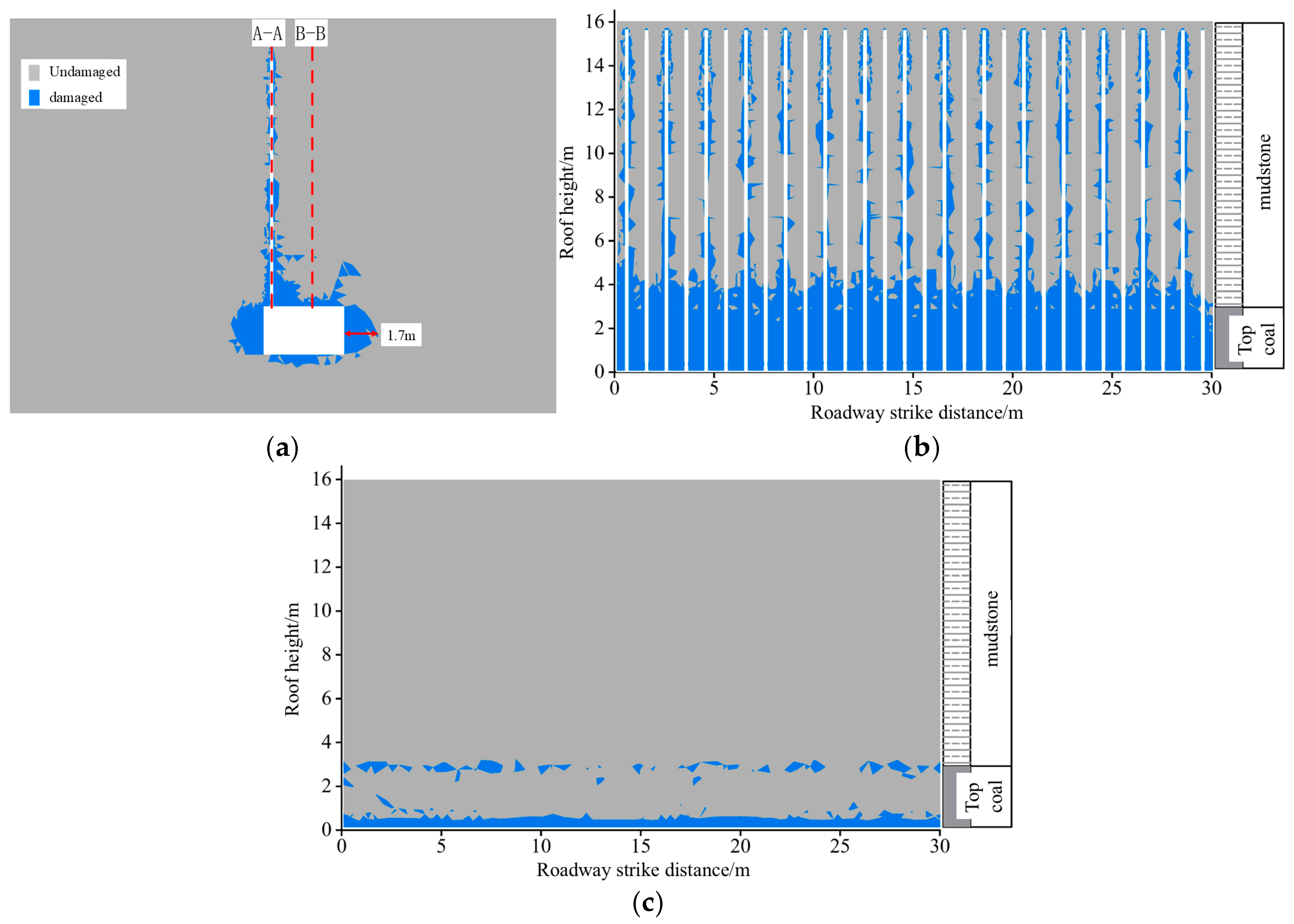
Figure 8 shows the plastic zone distribution in the roadway surrounding rock and the A-A and B-B cross-sections after static stress intervention in the advanced working face.

Figure 8.
(a) Plastic zone distribution of roadway surrounding rock; (b) Section A-A; (c) Section B-B.
From Figure 8, it can be seen that the coal body on both sides of the roadway has low strength, resulting in small-scale damage, with the maximum damage depth reaching 1.7 m. From the roof borehole profile A-A, it can be seen that, after static stress intervention, failure initially occurred within a 3 m zone of the roof coal with lower strength; the strength of the immediate roof is higher, and no continuous damage occurred, thus maintaining its integrity. From the tunnel roof profile B-B, it can be seen that the tunnel roof has not undergone significant damage.
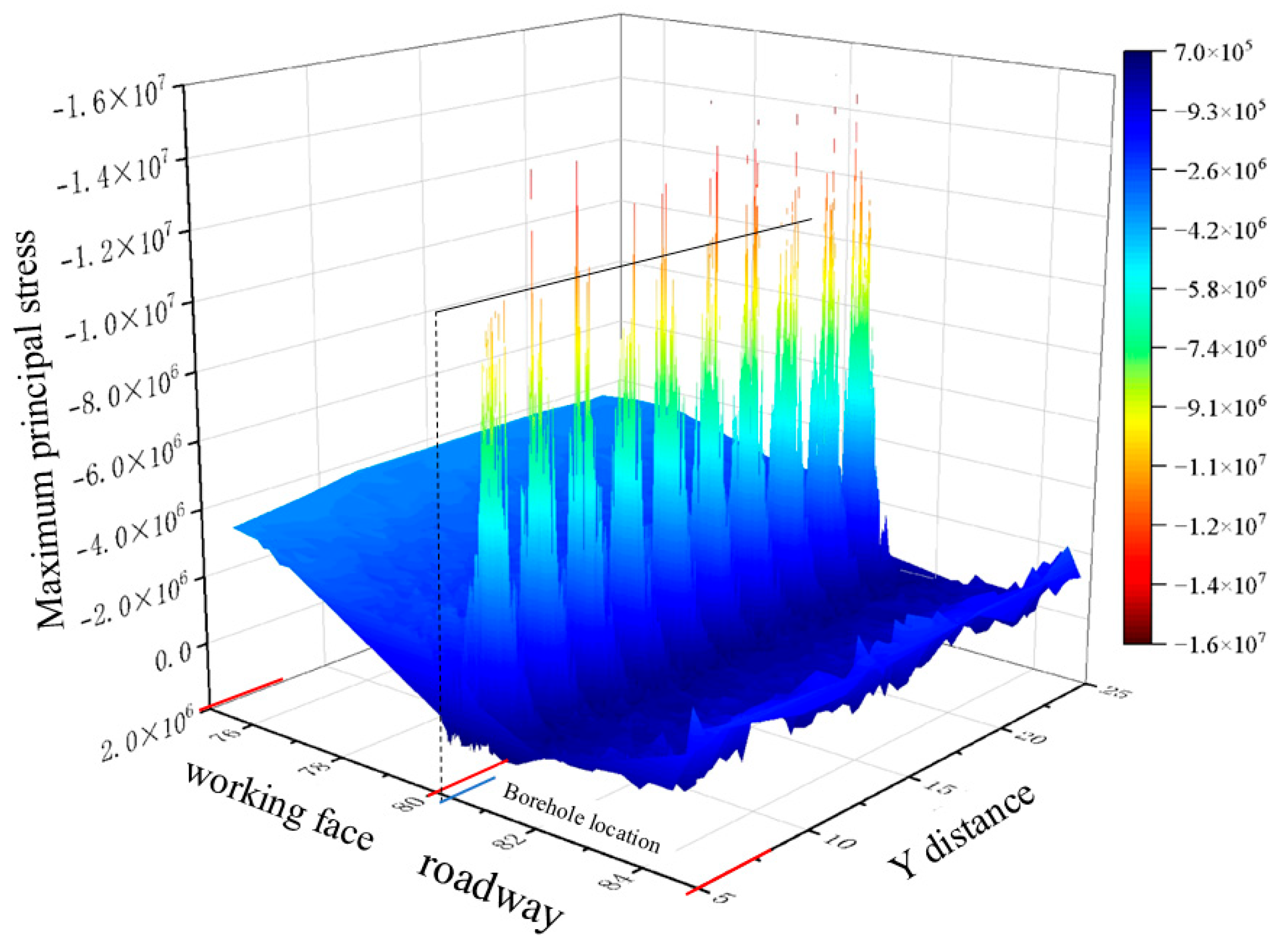
Figure 9 shows the distribution of stress in the tunnel roof after static stress intervention in the advanced working face.

Figure 9.
Stress distribution in the roof of the tunnel after drilling expansion.
Figure 9 reveals the three-dimensional stress field characteristics of the tunnel roof under static stress intervention. The tunnel roof on the right side shows a significant stress difference compared to the left side, where the working face has not yet been mined. The overall roof is in a low-stress pressure relief zone. However, a significant stress anomaly occurs at the position where static stress intervention is applied, with a peak stress of 15.5 MPa and a stress concentration coefficient of 2.01. The roof of the working face in the non-cutting region gradually returns to the original rock stress state at greater distances.
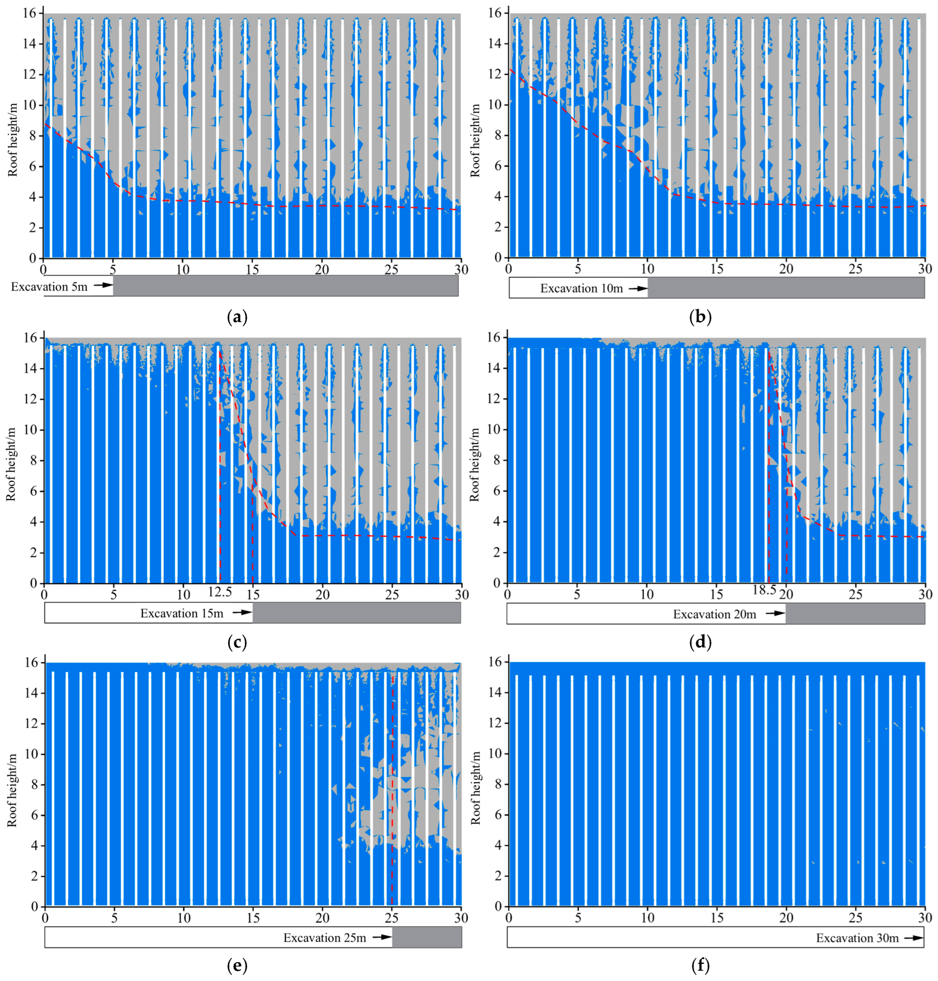
Figure 10 shows the distribution of plastic failure in the A-A cross-section of the roadway roof under varying advance distances.
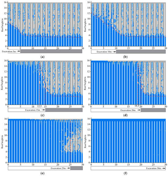
Figure 10.
Failure characteristics of section A-A at different excavation lengths: (a) excavation 5 m: (b) excavation 10 m; (c) excavation 15 m; (d) excavation 20 m; (e) excavation 25 m; (f) excavation 30 m.
From Figure 10, it can be seen that, after 5 m of excavation, the roof of the mined-out area begins to undergo plastic damage, with a maximum damage depth of 8.5 m. At this point, the area of the roof in the mined-out area that has undergone plastic damage accounts for 35.25%. After 10 m of excavation, the degree of plastic damage to the roof of the mined-out area increases further, with a maximum damage depth of 12.2 m. The area of the roof in the mined-out area that has undergone plastic damage accounts for 54.75%. After 15 m of excavation, the entire roof in the mined-out area within 12.5 m undergoes plastic damage, the periodic pressure step distance shortens, and the area of the roof in the mined-out area that has undergone plastic damage accounts for 84.2%. After 20 m of excavation, the entire roof in the mined-out area within 18.5 m undergoes plastic damage. After 25 m of excavation, nearly all of the roof in the mined-out area behind the excavation undergoes plastic damage. It can be seen that the roof drilling above the top coal is complete and no conduction crack is formed during the mining process.
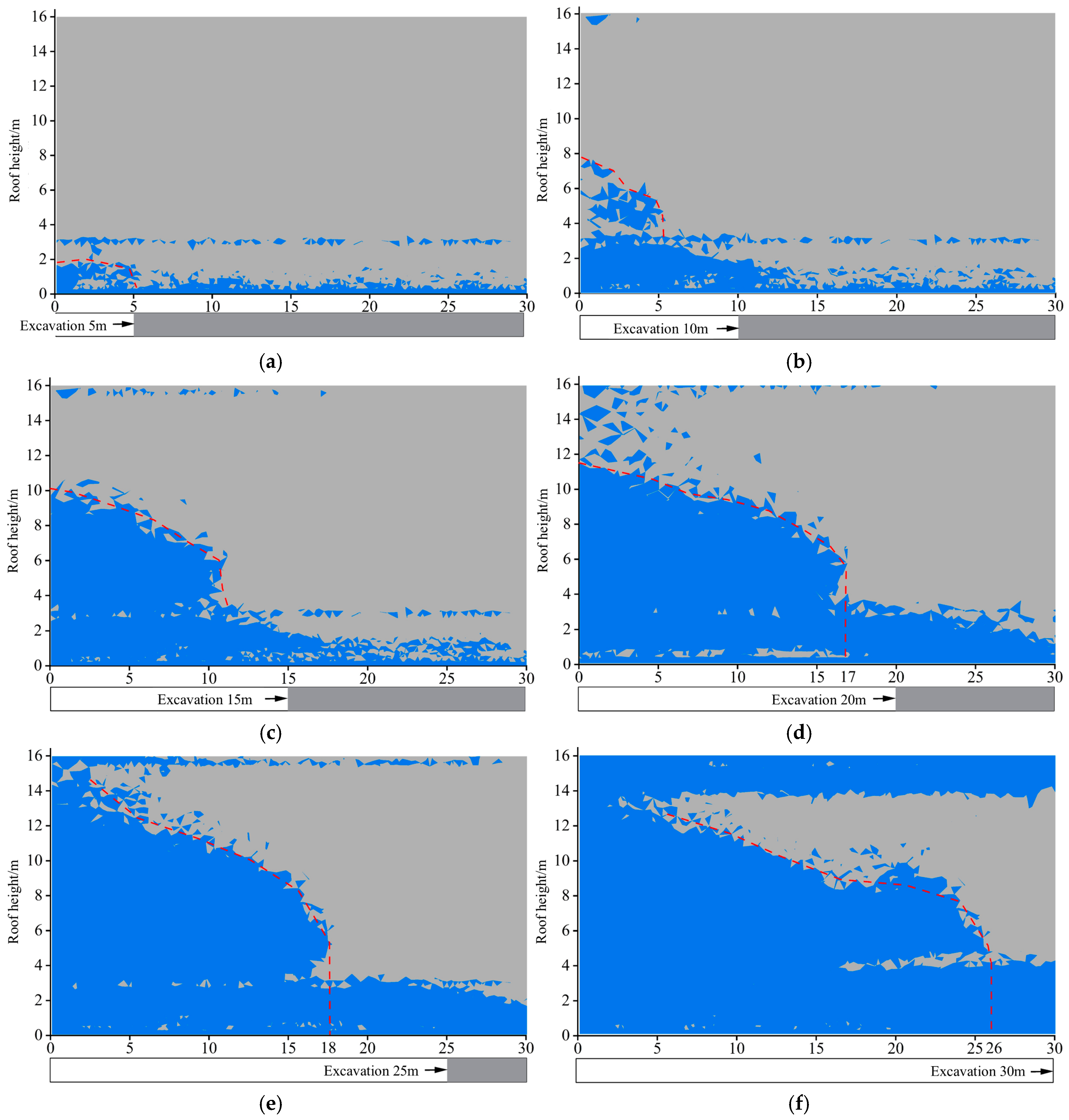
Figure 11 shows the distribution of plastic failure in the B-B cross-section of the roadway roof under varying advance distances.

Figure 11.
Failure characteristics of section B-B at different excavation lengths: (a) excavation 5 m; (b) excavation 10 m; (c) excavation 15 m; (d) excavation 20 m; (e) excavation 25 m; (f) excavation 30 m.
From Figure 11, it can be seen that, after 5 m of excavation, partial damage occurs in the roof coal, with a maximum damage depth of 2 m. The integrity of the upper roof remains relatively good. After 10 m of excavation, damage starts to occur in the tunnel roof within the 0–5 m range, with a maximum damage depth of 8 m. At this point, the roof damage lags behind the working face by 5 m. After 15 m of excavation, the roof in the 11 m range behind the tunnel experiences damage, with a maximum damage depth of 10.1 m. At this point, the roof damage lags behind the working face by 4 m. After 20 m of excavation, the roof in the 17 m range behind the tunnel experiences damage, with a maximum damage depth of 11.8 m. At this point, the roof damage lags behind the working face by 3 m. After 25 m of excavation, the roof in the 18 m range behind the tunnel experiences damage. At this point, the roof damage lags behind the working face by 7 m. After 30 m of excavation, the roof in the 26 m range behind the tunnel experiences damage. At this point, the roof damage lags behind the working face by 4 m. As the working face advances, the roof coal has relatively low strength and experiences plastic damage first. However, the strength of the immediate roof above is relatively high, causing it to lag behind the collapse of the mined-out area roof, which helps maintain the stability of the tunnel roof before the working face recovery.
The simulation results show that (1) the static stress intervention will form a high stress region near the borehole; (2) when the working face is pushed to the high stress area, the roof of the mined-out area is plastic damaged along the borehole layout face; (3) the roadway roof can remain stable before mining, which verifies the feasibility of static stress intervention in roof cutting.
5. On-Site Application and Effect Analysis
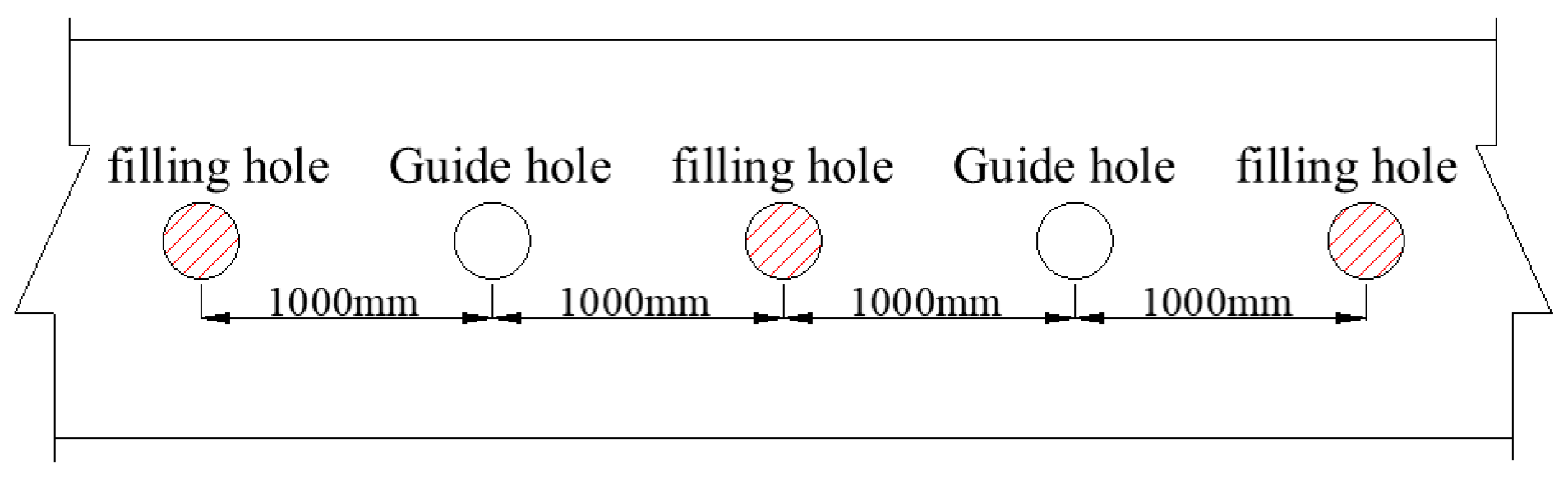
In actual engineering practice, continuous loading may lead to premature roof fractures. To provide a free surface and play a guiding role, a spaced loading method is used. Boreholes filled with static expansion agents are called charging holes, while boreholes without static expansion agents are called guiding holes. The spacing between charging holes and guiding holes is mainly determined by the performance of the static expansion agent and the strength of the roof rock. Based on previous engineering experience, three spacing options are available for the charging and guiding holes: 800 mm, 1000 mm, and 1200 mm. Through preliminary tests, a spacing of 1000 mm can effectively achieve roof cutting while maximizing material savings. The diagram of spaced loading is shown in Figure 12, and the scene of expansion borehole construction is shown in Figure 13.
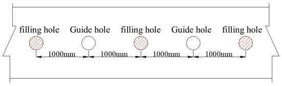
Figure 12.
Schematic diagram of spacer charging.
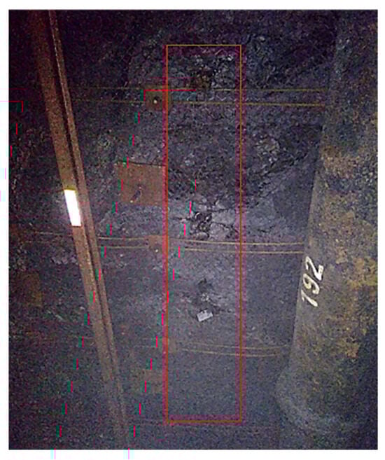
Figure 13.
Photographs of expansion holes in the field.
Based on the rock fragmentation theory [24], the borehole depth is determined to be 16 m. In the 150110 working face transportation roadway, a row of boreholes is drilled along the direction of the working face. Based on field tests and construction conditions, the borehole diameter is set to 65 mm, the borehole spacing is 1 m, the depth is 16 m, the distance from the coal pillar is 800 mm, and the boreholes are arranged vertically to the roof with expansion agents loaded into every other hole.
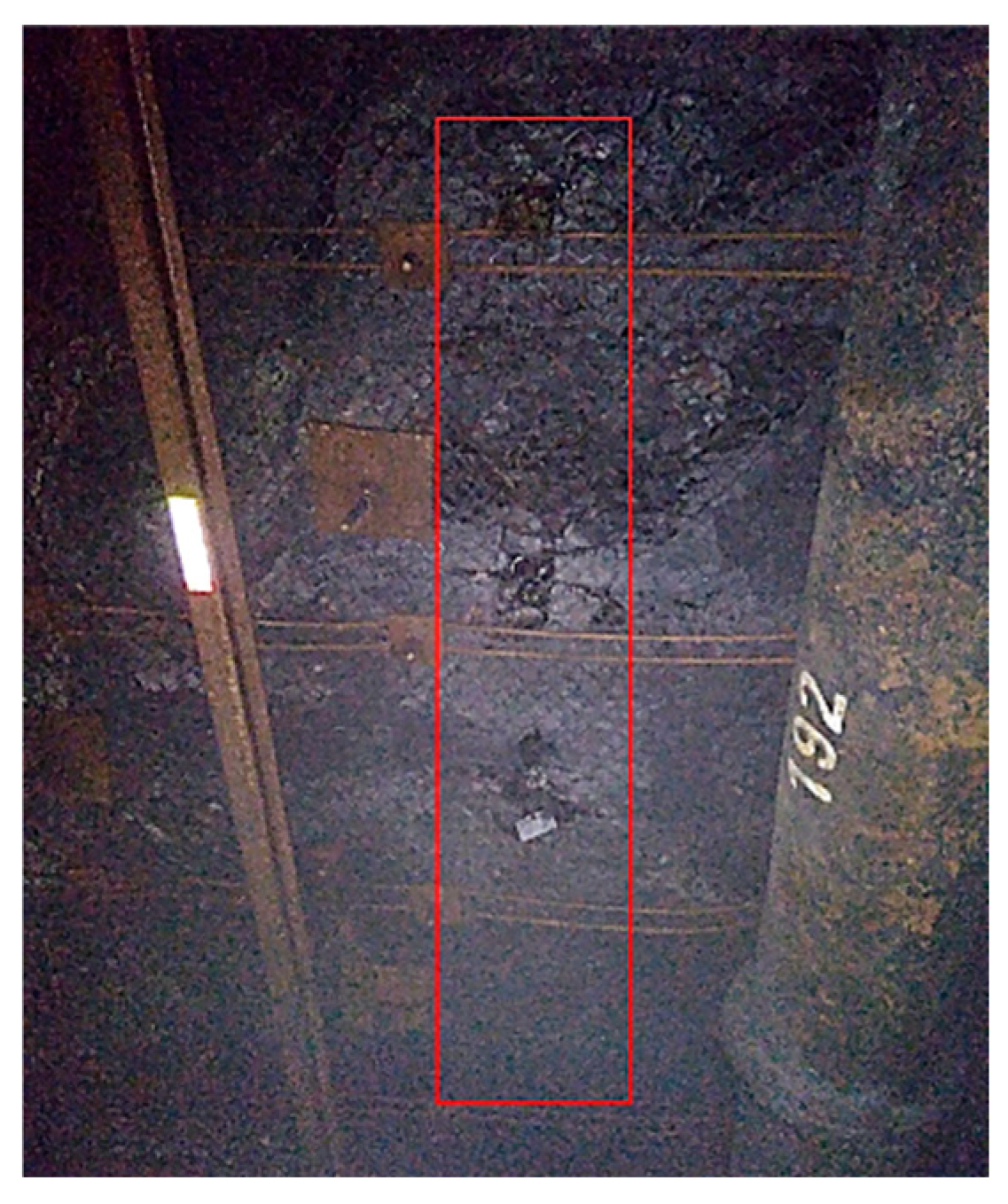
When the working face advances to the range of the roadway intervention, the working face continues to advance about 9 m, and the roof of the mined-out area collapses almost completely, with the collapse step distance reduced by about 6 m. As the temporary support with individual props and roof beams at the retreating end is removed, the roof of the side roadway in the mined-out area collapses in a timely manner. The roof collapse situation is shown in Figure 14.
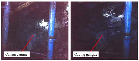
Figure 14.
Top slab collapse at the end of the roadway.
6. Conclusions
A method combining static expansion stress with mining-induced stress was proposed to achieve directional roof collapse in high-gas coal mines, addressing roof overhang hazards. Through theoretical modeling, FLAC3D numerical simulations, and field tests, the mechanical mechanism of static-mining stress synergy driving directional roof failure was revealed, and its engineering applicability was validated.
1. Mechanism Analysis: The expansion pressure (≥9.11 MPa) generated by static expansion agents within boreholes induces stress concentration zones at borehole locations. Superimposed with mining-induced stresses, tensile failure preferentially initiates along the borehole trajectory, achieving directional collapse. Theoretical calculations confirm that roof fracturing occurs at predetermined positions when the expansion pressure reaches the critical threshold.
2. Stress Redistribution: Static stress intervention significantly alters roof stress distribution, forming high-stress concentration zones around boreholes (peak stress: 15.5 MPa, stress concentration factor: 2.01) while maintaining borehole integrity. As the working face advances, plastic failure propagates along the borehole trajectory, validating the feasibility of stress synergy-driven collapse.
3. Field Application: Field implementation, employing a spaced charging configuration (1 m spacing, 65 mm borehole diameter, 16 m depth), reduced roof collapse intervals by 6 m, achieving effective mitigation of face-end overhang hazards.
4. Innovation and Significance: This study overcomes the limitations of conventional pre-cracking techniques by actively regulating the roof stress field through static stress intervention, enabling directional collapse without pre-existing fractures. The findings establish a novel theoretical and technical framework for roof stability control in high-gas coal mines.
Author Contributions
Conceptualization, B.H.; methodology, H.S. and X.R.; software, H.S. and J.Z.; validation, H.S., X.R. and J.Z.; writing—original draft preparation, H.S. and X.R.; writing—review and editing, B.H.; funding acquisition, B.H.; All authors have read and agreed to the published version of the manuscript.
Funding
This research received no external funding.
Data Availability Statement
The data presented in this study are available on request from the corresponding author.
Conflicts of Interest
The authors declare no conflicts of interest.
References
- Li, X.; Liu, S.; Fu, M.; Peng, B.; He, Y. Research and application of influencing factors of key parameters of roof cutting and pressure relief by dense drilling. Coal Sci. Technol. 2023, 51, 243–253. [Google Scholar]
- Ma, J.Q.; Li, X.H.; Yao, Q.L.; Xia, Z.; Xu, Q.; Shan, C.H.; Sidorenko, A.; Aparin, A. Numerical simulation on mechanisms of dense drilling for weakening roofs and its application in roof control. J. Cent. South Univ. 2023, 30, 1865–1886. [Google Scholar] [CrossRef]
- Zhang, B.; Wang, P.; Cui, S.; Fan, M.; Qiu, Y. Mechanism and surrounding rock control of roadway driving along gob in shallow-buried, large mining height and small coal pillars by roof cutting. J. China Coal Soc. 2021, 46, 2254–2267. [Google Scholar]
- Wang, M.; Zheng, H.; Ma, Z.; Mu, H.; Feng, X. Control Technology of Roof-Cutting and Pressure Relief for Roadway Excavation with Strong Mining Small Coal Pillar. Sustainability 2023, 15, 2046. [Google Scholar] [CrossRef]
- Zhang, K.; Liu, C.; Zhang, H.; Yue, X.; Liu, H. Research on Roof Cutting Pressure Relief of the Gob-Side Entry Retaining With Roadside Backfilling. Front. Earth Sci. 2022, 10, 835497. [Google Scholar] [CrossRef]
- Feng, G.; Fan, Y.; Wang, P.; Guo, J.; Gao, R.; Wen, X.; Zhang, P.; Zhu, L.; Qian, R.; Zhang, J. Fracture propagation law of hydraulic fracturing of rock-like materials based on discrete element method. J. China Coal Soc. 2024, 49, 2231–2246. [Google Scholar]
- Zhang, H.; Liu, C.; Chen, Z.; Yu, X.; Zhang, K.; Liu, H. Analysis and Application of Hydraulic Fracturing to Control Hard and Stable Roof in Initial Mining Stage. Sustainability 2023, 15, 10518. [Google Scholar] [CrossRef]
- Cheng, L.; Zhang, Z.; Jiang, P.; Yang, J. Research and application of stress field response mechanism based on roof hydraulic fracturing pressure relief. J. Min. Saf. Eng. 2023, 40, 722–729. [Google Scholar]
- Tai, Y.; Yu, B.; Xia, B.; Li, Z.; Xia, H. Research on stress release for the gob-side roadway using the roof-cutting technology with a chainsaw arm. R. Soc. Open Sci. 2020, 7, 191663. [Google Scholar] [CrossRef]
- Feng, S.; Chen, X.; Wang, L.; Li, L.; Li, X. Air Flow Movement Law in Working Face and Gob with Roof-Cutting and Pressure-Releasing Mining: A Numerical Simulation and Engineering Verification. ACS Omega 2023, 8, 25960–25971. [Google Scholar] [CrossRef]
- Li, S.; Li, Z.J.; Luo, M.K. Experimental Study on Reasonable Composition and Proportion of Coal and Rock Static Cracking Agent. Blasting 2018, 35, 137–141+153. [Google Scholar]
- Huang, H. Application and Research of Static Broken Used in High-Gas Coal Mine Roadway End Caving Roof Control; Taiyuan University of Technology: Taiyuan, China, 2014. [Google Scholar]
- Huang, X.P. Research on Optimization of Static Roof Cutting and Stress Releasing Parameters at the Side of Mining Roadway; Taiyuan University of Technology: Taiyuan, China, 2018. [Google Scholar]
- Wang, F.Q.; Li, Z.X.; Wu, J.; Gao, C.; Wang, J.N.; Ren, X.Y.; Ma, X.C.; Zhang, T. Study on Static Expansion and Roof Cutting Technology at End of Large Mining Height Working Face. Coal Technol. 2023, 42, 95–99. [Google Scholar]
- Hao, B.Y.; Li, Z.H.; Huang, H.; Zhao, G.L. Research and Application of Static Crushing Technology Handled Roadway Roof Overhang in High-gas Coal Mine. Blasting 2015, 32, 109–114. [Google Scholar]
- Xiang, H.T.; Yan, G.C.; Ding, H.Q.; Kou, K.B.; Li, G. Research and Application of Static Precrack Technology of Roof Before Initial Mining in High Gas Mine. Min. Res. Dev. 2022, 42, 14–19. [Google Scholar]
- Ding, H.; Yan, G.; Kou, K.; Dong, J.; Xiang, H. Study on the technology of roof cracking caused by static crushing agent inXiaochang Coal Industry. Min. Saf. Environ. Prot. 2023, 50, 100–104+110. [Google Scholar]
- Vu, T.T.; Do, S.A. Determination of the rock mass displacement zone by numerical modeling method when exploiting the longwall at the Nui Beo Coal Mine, Vietnam. Min. Miner. Depos. 2023, 17, 59–66. [Google Scholar] [CrossRef]
- Dmytro, B.; Olena, S.; Hapieiev, S.; Prykhodchenko, V. Multifactorial analysis of a gateroad stability at goaf interface during longwall coal mining—A case study. Min. Miner. Depos. 2023, 17, 9–19. [Google Scholar]
- Yang, X.; Yang, G.; Huang, R.; Wang, Y.; Liu, J.; Zhang, J.; Hou, S. Comprehensive study on surrounding rock failure characteristics of longwall roadway and control techniques. Appl. Sci. 2021, 11, 9795. [Google Scholar] [CrossRef]
- Li, P.; Yang, C.; Fu, X.; Li, J.; Jin, D. Reinforcement of Insufficient Transverse Connectivity in Prestressed Concrete Box Girder Bridges Using Concrete-Filled Steel Tube Trusses and Diaphragms: A Comparative Study. Buildings 2024, 14, 2466. [Google Scholar] [CrossRef]
- Hou, C.J.; Ma, N.J. Stress in in-seam roadway sides and limit equilibrium zone. J. China Coal Soc. 1989, 14, 21–29. [Google Scholar]
- Huang, W.P.; Gao, Y.B.; Wen, Z.J.; Gao, L. Technology of gob-side entry retaining using concrete-filled steel tubular column as roadside supporting. J. China Univ. Min. Technol. 2015, 44, 604–611. [Google Scholar]
- He, M.C.; Gao, Y.B.; Yang, J.; Guo, Z.B.; Wang, E.Y.; Wang, Y.J. The energy-gathered roof cutting technique in non-pillar mining and its impact on stress evolution of surrounding rocks. Chin. J. Rock Mech. Eng. 2017, 36, 1314–1325. [Google Scholar]


Disclaimer/Publisher’s Note: The statements, opinions and data contained in all publications are solely those of the individual author(s) and contributor(s) and not of MDPI and/or the editor(s). MDPI and/or the editor(s) disclaim responsibility for any injury to people or property resulting from any ideas, methods, instructions or products referred to in the content. |
© 2025 by the authors. Licensee MDPI, Basel, Switzerland. This article is an open access article distributed under the terms and conditions of the Creative Commons Attribution (CC BY) license (https://creativecommons.org/licenses/by/4.0/).