Article

Distribution Characteristics of Mining-Induced Stress Fields and Surrounding Rock Control Technology in Adjacent Working Faces Within Fold Structure Zones

1
Institute of Mining and Coal, Inner Mongolia University of Science and Technology, Baotou 014010, China
2
Inner Mongolia Key Laboratory of Mining Engineering, Baotou 014010, China
3
Inner Mongolia Research Center for Coal Safety Mining and Utilization Engineering and Technology, Baotou 014010, China
4
Inner Mongolia Cooperative Innovation Center for Coal Green Mining and Green Utilization, Baotou 014010, China
5
China Energy Trading Group Co., Ltd., Beijing 100089, China
6
Sunsangou Coal Mine of Inner Mongolia Hongyuan Coal Group Co., Ltd., Ordos 010300, China
*
Author to whom correspondence should be addressed.
Processes 2025, 13(5), 1534; https://doi.org/10.3390/pr13051534
Submission received: 12 April 2025 / Revised: 5 May 2025 / Accepted: 14 May 2025 / Published: 16 May 2025
(This article belongs to the Special Issue Advances in Coal Processing, Utilization, and Process Safety)

Abstract

:
Mining operations in fold structure zones are often subject to dynamic disasters due to the influence of tectonic topography. To explore the interaction between the tectonic stress field and the mining-induced stress field throughout the entire mining process of adjacent working faces in fold structure zones, this study adopts a comprehensive research methodology that integrates field investigations, theoretical analysis, numerical simulations, and industrial experiments. The stress distribution characteristics before and after mining in fold structure zones are systematically analyzed to elucidate the evolution laws of stress and displacement in coal seams, reveal the mechanisms of surrounding rock instability, identify high-risk locations for roof collapse, and propose targeted surrounding rock control strategies for practical application. The key findings of this research are as follows: (1) In fold structure zones, the horizontal stress is significantly influenced by tectonic factors, whereas the vertical stress is predominantly affected by mining activities. (2) The evolution of the mining-induced stress field in fold structure zones is jointly governed by the initial tectonic stress and the mining-induced stress. The advancing position of the working face determines the specific locations of stress concentration, while the tectonic stress regulates the intensity of stress concentration across different regions. (3) The mechanism of surrounding rock failure and instability in fold structure zones is irreversible, with the stress field being a superposition of tectonic and mining-induced stresses. The extent of failure depends on the combined stress concentration at specific locations, which is directly correlated with the distribution of the initial tectonic stress field. (4) Based on the failure patterns of surrounding rock in fold structure zones, a coordinated control strategy incorporating supplementary roof support was developed, along with detailed parameter specifications. The practical implementation of this strategy ensured the stability of surrounding rock during mining through fold structure zones, effectively preventing incidents of roof collapse or rib spalling.

1. Introduction

In the current global energy landscape, coal remains a crucial foundational energy resource in ever-increasing demand. However, we must confront the reality that as easily accessible shallow coal deposits gradually deplete, coal mining operations are inevitably extending to deeper strata and geologically complex regions. Fold structures, as common geological phenomena resulting from crustal movements, are widely distributed in coal-bearing strata. These fold structures significantly influence the occurrence state of coal seams, leading to frequent dynamic disaster incidents in such mining areas, including roof collapse, rib spalling, and floor heave [1,2]. The formation process of fold structures involves intense stress interactions, resulting in markedly heterogeneous and complex stress distributions within coal seams and surrounding rock masses. During the extraction of folded coal seams, the distribution characteristics of the stress field directly govern the stability of the working face surrounding rock [3,4]. Therefore, analyzing the impact of underground mining activities on stress environments in fold structure zones and implementing targeted prevention measures against mining-induced dynamic disasters under such geological conditions holds significant theoretical value for guiding safe and efficient coal mining operations in structurally complex terrains.
Scholars both domestically and internationally have conducted extensive research on the stress field distribution characteristics in fold structure zones through theoretical analysis, numerical simulation, and field measurement methods, yielding a series of significant research outcomes. Based on a large number of measured data, He Hu et al. [5] monitored seismic events during coal seam mining in folded structure zones and studied the evolution patterns of these events. They found that intense seismic events are more likely to occur in the syncline axis, with a higher probability of impact hazards compared to other areas. Wang Cunwen et al. [6] used a combination of mining pressure theory and numerical simulation to analyze the mechanism of rockburst caused by folded structures. They also provided case studies. The research concluded that folded structures can be divided into five zones based on stress conditions, with the syncline axis, anticline axis, and fold limbs being more prone to impact disasters. Wang Zhanling et al. [7] investigated the changes in roadway support under the influence of folded structure stress and explored methods to improve roadway support. They found that using high-prestress bolts for roadway support can ensure the integrity of the roof coal and rock and significantly reduce roadway deformation. Jing Guangcheng et al. [8] used theoretical analysis and numerical simulation methods combined with engineering examples to summarize the evolution of mining-induced stress and energy consumption patterns in folded structure working faces. Chen Guoxiang et al. [9] studied the relationship between horizontal stress in folded structure coal seams, stress changes due to mining disturbances, and rockburst. They also discussed the causes of rockburst hazards. Kang Hongpu et al. [2] conducted in situ measurements and numerical simulations to analyze the stress distribution around large-scale syncline structures. They found that syncline structures significantly affect the stress distribution underground, especially in the syncline axis, where horizontal stress increases sharply. In contrast, the syncline limbs have relatively lower horizontal stress, with the increase in horizontal stress being much higher than that of vertical stress. Wang Shengben et al. [10] theoretically analyzed the relationship between geological structure zones and the direction of stress. They used numerical simulation to establish a numerical model of folded structures and studied the characteristics and patterns of overburden movement and stress distribution in folded structure zones. Guo Changbao et al. [11] used ANSYS software for numerical simulation. They designed two excavation schemes with different excavation locations and directions, as well as two tunnel types: horseshoe-shaped and circular arch with straight walls. They studied the stress redistribution characteristics of surrounding rock in tunnels at different angles under the influence of folded structures and the probability of impact hazards occurring in tunnels at different angles. Shi Qiang et al. [12] investigated the stress distribution characteristics of coal seams in complex folded structures. They found that a large amount of energy is accumulated during the formation of folded structures, and this accumulated energy is an important factor leading to instability and failure in working faces. Zhou Ye et al. [13] used FLAC to conduct numerical simulation experiments on two-dimensional single-layer folds, mainly discussing the evolution patterns of maximum principal stress and horizontal strain during the deformation process of single-layer folds. Wang Jinsheng [14] studied the impact of folded structures on coal mine mining. He found that folded structures bring difficulties to roadway layout and roof management and that gas accidents are more likely to occur around the axes of anticlines and synclines. Cao Anye et al. [15] used in situ measurement data and numerical simulation to study the stress evolution patterns of the roof, floor, and coal seam during mining in folded structure zones. They found that the vertical and horizontal stress field characteristics vary in different folded zones, with horizontal stress playing a dominant role. Chen Ming [16] analyzed the causes of folds theoretically and studied their impact on coal seam mining. He found that the internal accumulated stress in folded structures creates numerous fractures, making the coal seam roof unstable. During mining, the release of structural stress increases the probability of roof collapse accidents. Wu Yun et al. [17] used the UDEC numerical software to analyze the destruction and deformation patterns of the overlying strata above the working face and the development characteristics of fractures in the overlying strata during coal mining, with different mining steps and stages. Bu Wankui et al. [18], based on the theory of curved beams and using geological data such as the folded structure of the working face, conducted research on the changes in overburden and stress distribution patterns in folded structures through theoretical analysis and numerical calculations. Liu Botao et al. [19] used numerical simulation to analyze the deformation and destruction characteristics of the overlying strata under different folded structures during mining. The results showed that different folded structures lead to different forms of overburden deformation and destruction. Anticlines inhibit the subsidence of the overlying strata, while synclines have the opposite effect. Tian Chen et al. [20] used three-dimensional similarity simulation to explore the patterns of overburden breakage and mining pressure manifestation during the mining process of large-height working faces in folded structure zones. Tang Long et al. [21] obtained the stress evolution laws and distribution characteristics of the surrounding rock of fold structures through numerical simulation and field measurement methods. Lu Cai et al. [22] studied the stress evolution during coal mining in fold areas and analyzed the stress distribution characteristics of coal and rock in different positions of working faces in fold areas.
While the aforementioned scholars have investigated the stress environment in fold structure zones, research on the interaction between the tectonic stress field and mining-induced stress field throughout the entire mining process of adjacent working faces in such zones remains limited and requires further elaboration. This study, based on the mining conditions of adjacent working faces in the 12# coal seam at the Bulianta Coal Mine in Shendong, addresses critical practical challenges, including intense strata pressure manifestations and frequent roof collapse incidents in fold structure working faces. By adopting an integrated research methodology that combines field investigations, theoretical analysis, numerical simulations, and industrial experiments, this study systematically analyzes the stress distribution characteristics before and after mining in fold structure zones. The objectives are to elucidate the stress and displacement evolution laws of coal seams in these zones, uncover the mechanisms of surrounding rock instability during mining, pinpoint risk-prone locations for roof collapse, and develop and implement targeted surrounding rock control strategies.

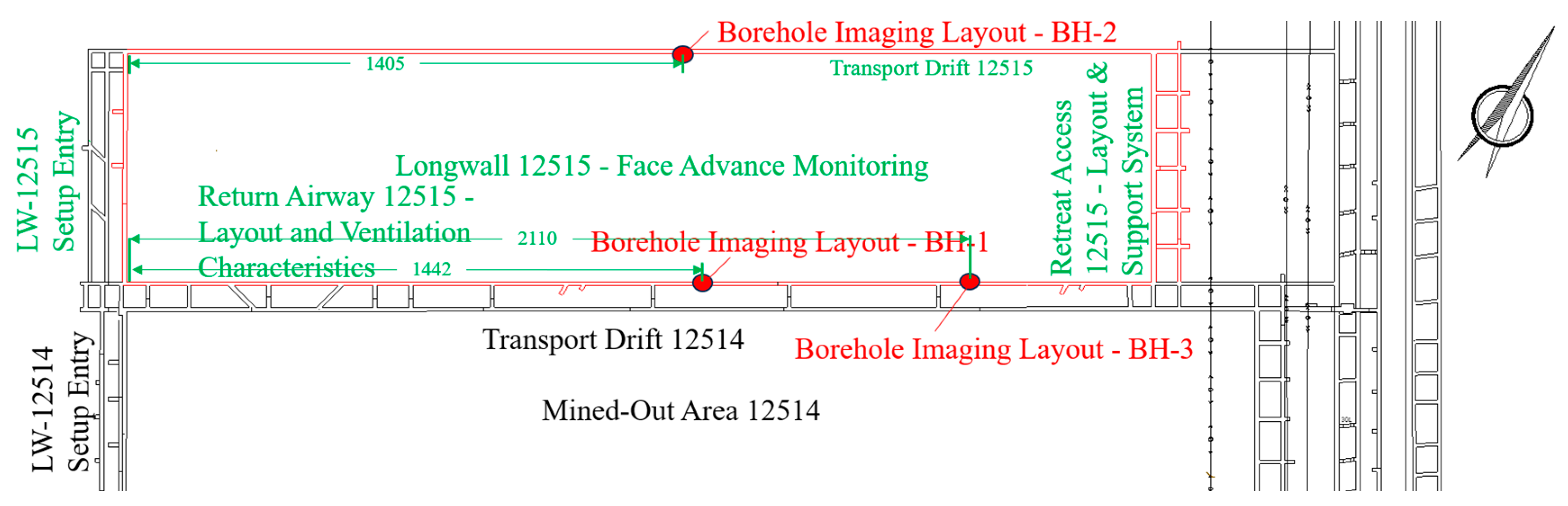
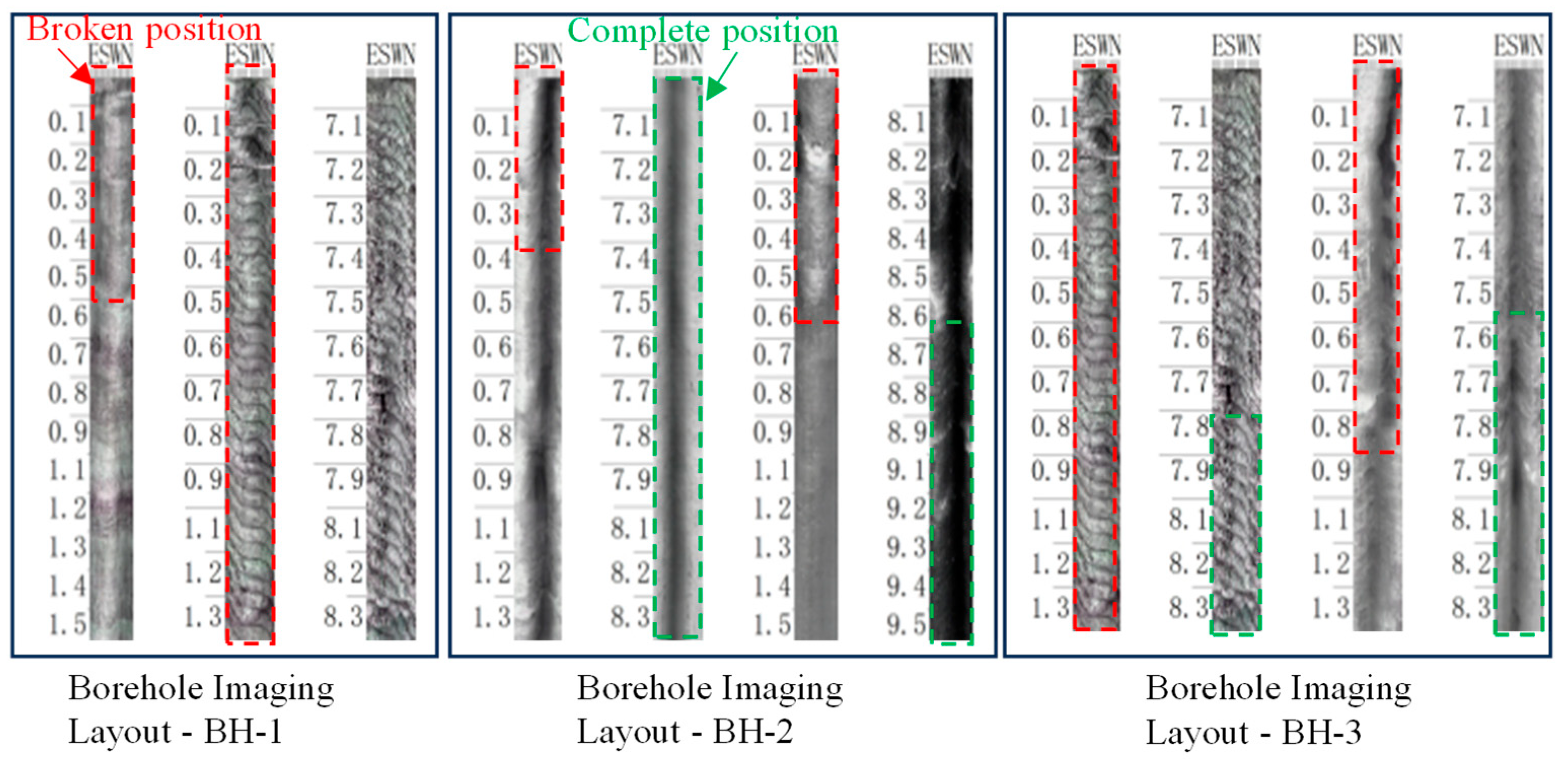
2. Case Study Overview

The Bulianta Coal Mine is located in the northeastern part of the Ordos Plateau, a typical loess highland region. The 12515 working face of the Bulianta Coal Mine has a total length of 327.7 m. The fully mechanized mining face is arranged along the strike of the coal seam, with a strike length of 2941.7 m and a burial depth ranging from approximately 270 to 290 m. The mining method employed is the fully mechanized longwall mining with a single-pass full-seam height extraction and the caving method for goaf management. A 30-m-wide protective coal pillar is left between the 12515 working face and the 12514 goaf. Both the tailgate and headgate of the 12515 working face are driven along the floor with a rectangular cross-section design (width × height = 5400 mm × 4300 mm). The fold structure zones are prominently distributed within the mining area of the 12515 working face. The geological overview of the 12515 working face is illustrated in Figure 1.
As shown in Figure 1a,d, the 12 coal working face is significantly distributed in the folded structure area. Among them, the 12515 working face is an unmined working face. It is affected by the folded structure and the mining of adjacent working faces at the same time, and there is a high risk of roof fall. Combined with the distribution of roof fall positions in other working faces, it can be known that the roof fall risk area is located in the position with large undulations of the folds. Therefore, the risk location is determined as shown in Figure 1b.
It can be known from the engineering data that the roof strata of the 12515 working face are mainly composed of sandstone, sandy mudstone, and siltstone. To investigate the surrounding rock structure in the easily caving zones of the roof at the Bulianta 12515 working face, one borehole each was drilled in three high-risk caving areas along the return airway and the belt roadway. The boreholes had a diameter of 75 mm and a depth of 15 m, with a 60-degree angle to the roof of the working face. The design of the borehole inspection scheme and the layout of the boreholes are illustrated in Figure 2, and the results of the borehole inspection are presented in Figure 3.
As shown in the figures, analysis of the borehole inspection video and the borehole unfolding diagram reveals the following observations: Within the range of 0–1.5 m from the roof, the fractures are densely interwoven, and the rock mass is severely fragmented. The coal body, after being cut, is broken into blocks of varying sizes, with a significant accumulation of coal fragments around the borehole wall. Partial collapse of the borehole is observed, showing a tendency to connect with the overlying goaf. In the range of approximately 7–8 m from the roof, the surrounding rock exhibits multiple horizontal, vertical, and inclined fractures. These fractures are large in scale and widely extended, containing a small amount of fine debris. Within the range of about 8–9.5 m from the roof, only a few small-scale fractures are locally present. The borehole wall is relatively smooth, and the surrounding rock maintains good integrity.
A one-month observation of mine pressure was conducted in the area where the 12514 working face passed through the fold structure. The pressure changes at different support positions under various advancement degrees were statistically analyzed. The mine pressure manifestation surface diagram of the 12514 working face passing through the fold area is shown in Figure 4. A total of 24 periodic pressure arrivals were statistically analyzed in the horizontal and fold areas. The monitoring data of the working face head, middle, and tail sections were respectively statistically analyzed. The average values of periodic pressure arrivals, dynamic load coefficients, and pressure duration at the three positions were plotted into curves, as shown in Figure 5.
As shown in Figure 4, within a certain range before and after the working face passes through the fold zone, the range of roof pressure increases, the pressure is obviously irregular, the pressure step distance decreases, and there is a significant continuous pressure, with the pressure distance increasing. According to the statistics of periodic pressure in Figure 5, the manifestation of mine pressure can be divided into two stages. The first stage is when the working face is being mined in the horizontal area, within which the maximum periodic pressure step distance is 11.2 m, the minimum is 4.9 m, and the average periodic pressure step distance is 7.4 m; during the pressure period, the maximum average dynamic load coefficient is 1.39, the average is 1.30, and the average pressure distance is 4.3 m. The pressure intensity is moderate, and the overall pressure change is not significant. The second stage is when the working face enters the fold influence area. Within this range, the maximum periodic pressure step distance is 14 m, the minimum is 5.5 m, and the average periodic pressure step distance is 8.9 m. During the pressure period, the maximum average dynamic load coefficient is 1.41, the maximum pressure distance is 17 m, the average pressure distance is 7.7 m, and the average dynamic load coefficient is 1.40. This stage is characterized by strong pressure intensity. Whether from the pressure distance or the pressure intensity, there is an increase to varying degrees after entering the fold influence area. The working face is in a long-term pressure state. Under the circumstances of increased mine pressure intensity and duration, the roof is prone to a roof fall accident.

3. Stress Distribution Characteristics and Dynamic Evolution Laws of Adjacent Working Faces in Fold Structure Zones

Due to the unique coal seam occurrence conditions in fold structures, the stress field distribution within the surrounding rock of the working face exhibits significant variability. Therefore, analyzing the in situ stress characteristics before mining in fold-affected working faces, as well as the dynamic stress evolution and distribution patterns of the surrounding rock during the entire mining process of adjacent working faces, is crucial for ensuring the efficient and safe extraction of fully mechanized working faces.

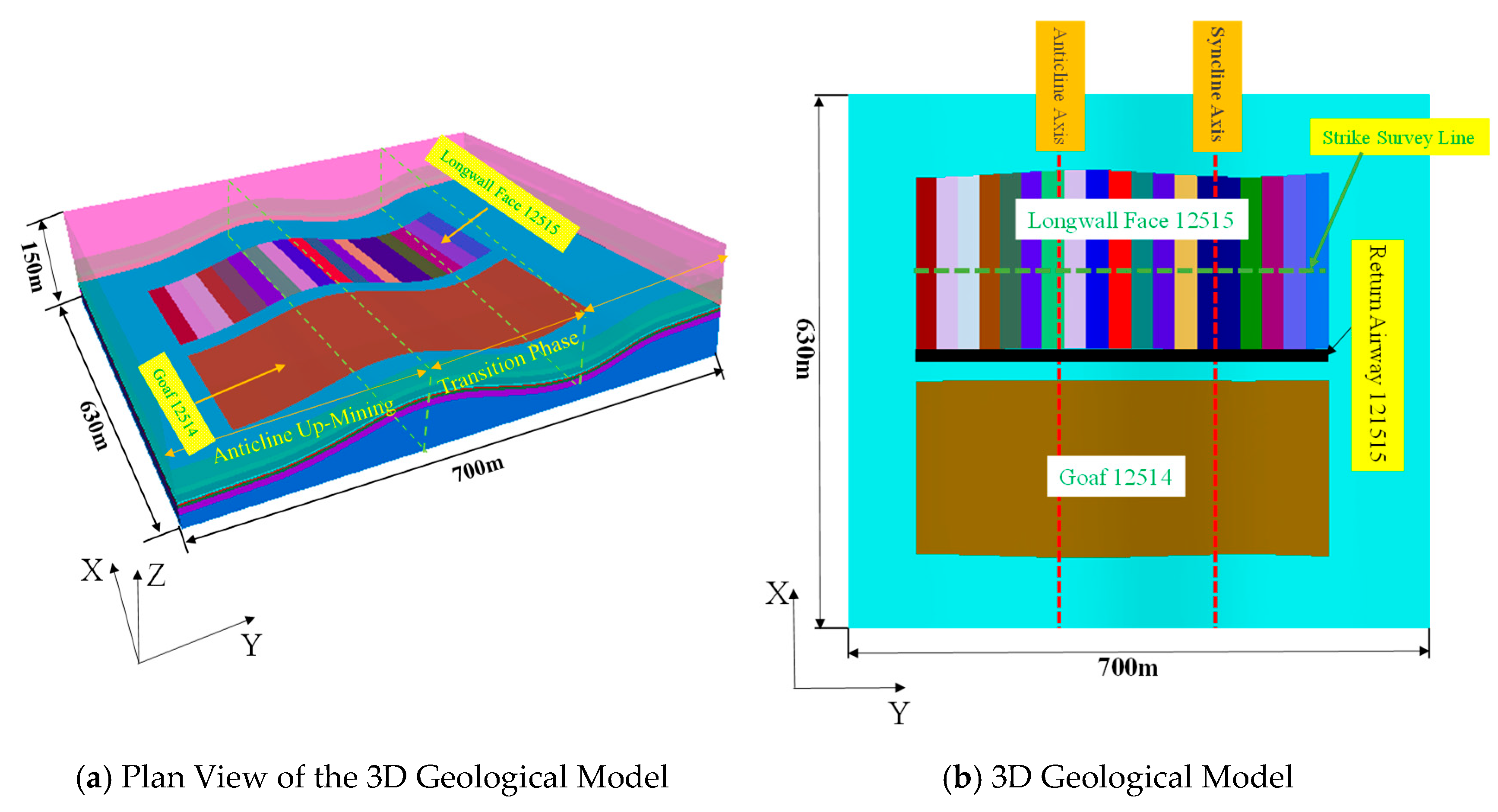
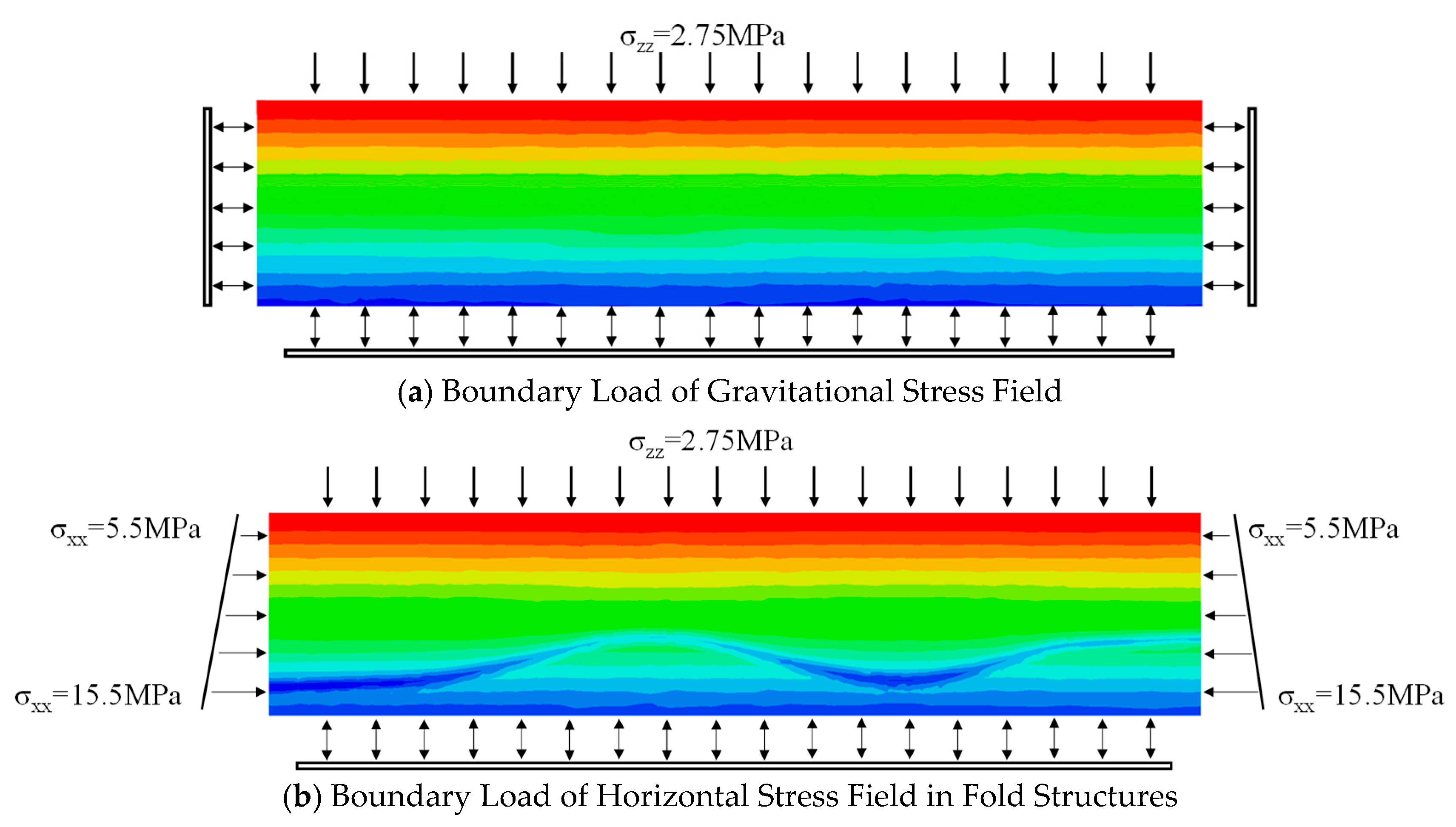
3.1. Establishment of Numerical Model

Based on the actual layout of adjacent working faces and the real distribution of folds, a FLAC3D numerical model was established using the Mohr-Coulomb criterion. The model dimensions are 700 m × 630 m × 150 m (length × width × height), with fold parameters set to a wavelength of 500 m, an amplitude of 40 m, and a limb angle of 150°. The coal seam thickness is 7.3 m, with a burial depth ranging from 270 m to 290 m, and the dip length of the two working faces is 330 m. There exists a 110-m-thick overlying rock stratum from the ground surface to the top of the model. According to geological data, this stratum has an average volume force of 25 kN/m3. Therefore, a vertical load of 2.75 MPa is applied to the upper part of the model to simulate the self-weight of the overlying loose rock mass. Fixed constraints are applied to the bottom and surrounding sides of the model. The numerical simulation model is illustrated in Figure 6. Based on the engineering geological data, the maximum horizontal principal stress of the surrounding rock at the working face of the 12514 fold structure was measured to range from 1.61 to 1.93 times the vertical stress. Given the complexity and risk associated with the structural stress environment of the 12515 fold structure, the lateral pressure coefficient was iteratively adjusted to ensure that the stress distribution in the fold model aligns with the actual conditions. Consequently, a maximum lateral pressure coefficient of 2.1 was established for the numerical simulation. The physical and mechanical parameters of the rock and coal are listed in Table 1.
The horizontal stress field in the fold-affected zone is composed of both the tectonic stress and the self-weight stress components. To establish a reliable numerical model that accurately reflects the initial in situ stress state of the coal and rock mass in the fold-affected zone, the horizontal displacement constraints on the x-direction sides of the model were removed, and horizontal stress boundary conditions were applied. A horizontal tectonic stress of 5.5 MPa was applied at the top of the model, and 15.5 MPa was applied at the bottom, creating a linear gradient characteristic of fold structures. The boundary load application method for the model is illustrated in Figure 7.

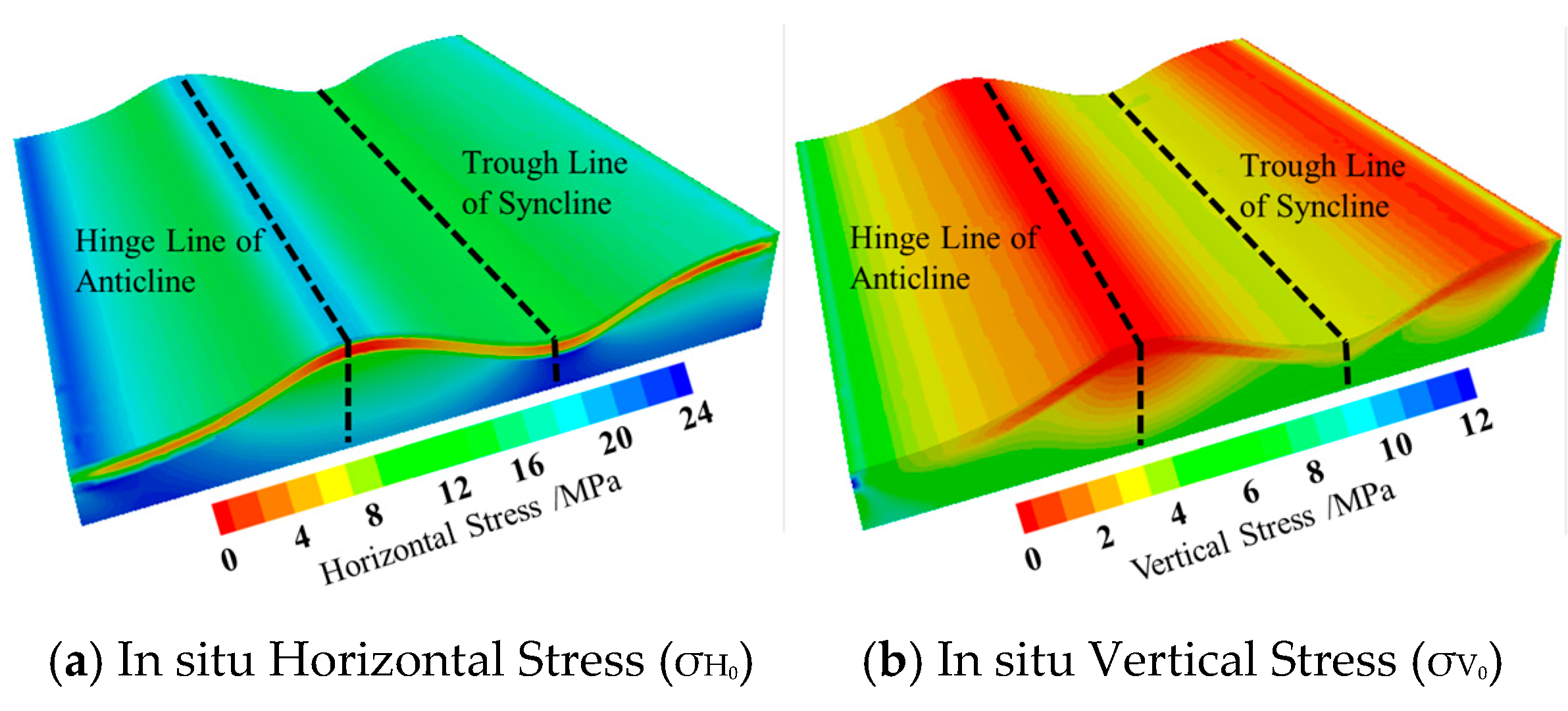
3.2. Initial In Situ Stress Distribution Characteristics in Fold Structure Zones

To analyze the stress distribution characteristics of surrounding rock during mining activities in fold structure areas, it is essential to first examine the initial stress distribution within these regions. The stress nephogram of the surrounding rock in the fold structure area, following the excavation of the working face, is depicted in Figure 8.
The initial horizontal stress in the fold structure area is generally greater than the vertical stress. As shown in Figure 8a, the horizontal stress of the surrounding rock in the fold structure area is concentrated at the top of the anticlinal axis coal seam and the bottom of the synclinal axis coal seam. The horizontal stress in the coal seam is generally relieved, while the horizontal stress in other areas is relatively uniform. As illustrated in Figure 8b, the vertical stress of the surrounding rock in the fold structure area exhibits gradient relief behind the anticlinal axis and beyond the synclinal axis. The stress relief zones on both flanks of the anticlinal axis display a relatively symmetrical arch-shaped distribution. Overall, the vertical stress of the surrounding rock in the uplifted terrain transfers to the downward concave terrain, with significant gradient changes in vertical stress on both flanks of the syncline, indicating poor stability of the coal-rock mass.

3.3. Stress Distribution Characteristics in Adjacent Gob Areas of Fold Structure Zones

Under the layout conditions of adjacent working faces in fold structure zones, the stress redistribution within the surrounding rock after the completion of mining in the upper working face and the formation of the gob area directly influences the stress field distribution in the current working face area. Therefore, based on the initial stress field, the post-mining state of the upper working face was simulated to further investigate the stress field distribution characteristics of the surrounding rock prior to mining in the current working face. The stress nephogram of the surrounding rock in the adjacent gob area of the fold structure zone is shown in Figure 9.
As illustrated, after the collapse of the upper working face, the horizontal stress in the fold structure is concentrated in the anticlinal axis region, while the horizontal stress in the synclinal flanks is released. The vertical stress in the fold structure, influenced by the superposition of lateral abutment pressure from the gob area, is concentrated laterally in the synclinal flanks of the gob area. At a lateral distance of 30 m from the gob area, which corresponds to the boundary of the 12515 working face, the horizontal stress distribution in the coal seam roof is not significantly affected by the gob area, whereas the vertical stress is notably influenced by the lateral stress concentration from the gob area.
In summary, the horizontal stress in the fold structure zone is significantly influenced by tectonic factors, with stress concentration locations remaining consistent before and after mining. Post-mining, the horizontal stress in the synclinal axis and its flanks is gradually released. Conversely, the vertical stress in the fold structure zone is more affected by mining activities. Upon completion of the working face, internal stress is released, and stress concentration becomes evident at the synclinal axis and its flanks outside the working face. The anticlinal axis, due to tectonic influences, experiences stress release, resulting in a lower stress concentration compared to the synclinal axis. Therefore, prior to mining in the current working face, the surrounding rock in the synclinal flanks near the coal pillar is subjected to stress concentration due to the combined effects of the fold structure and adjacent gob area, posing a threat to the stability of the surrounding rock. Further investigation into the stress field conditions during the mining of this working face is urgently needed.

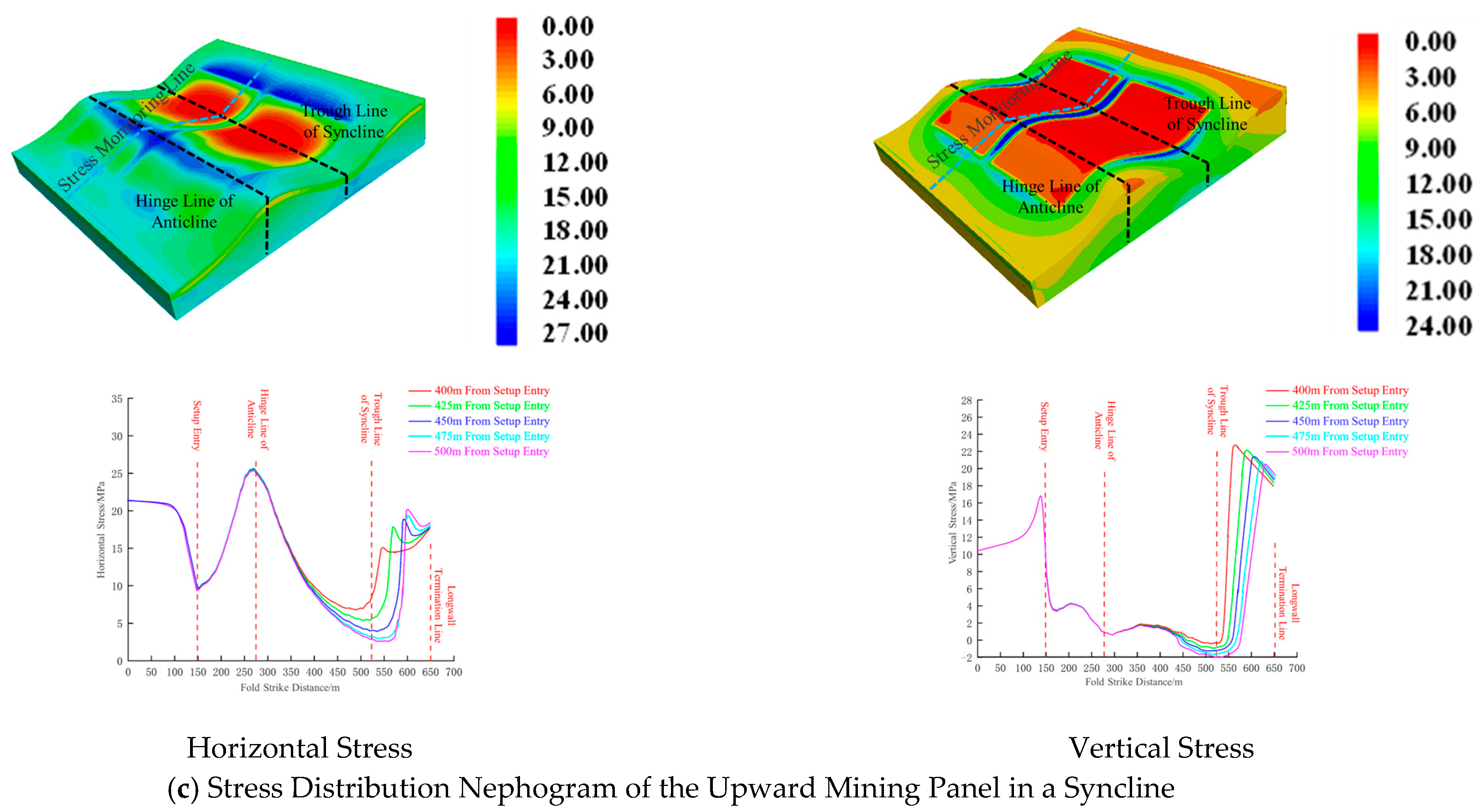
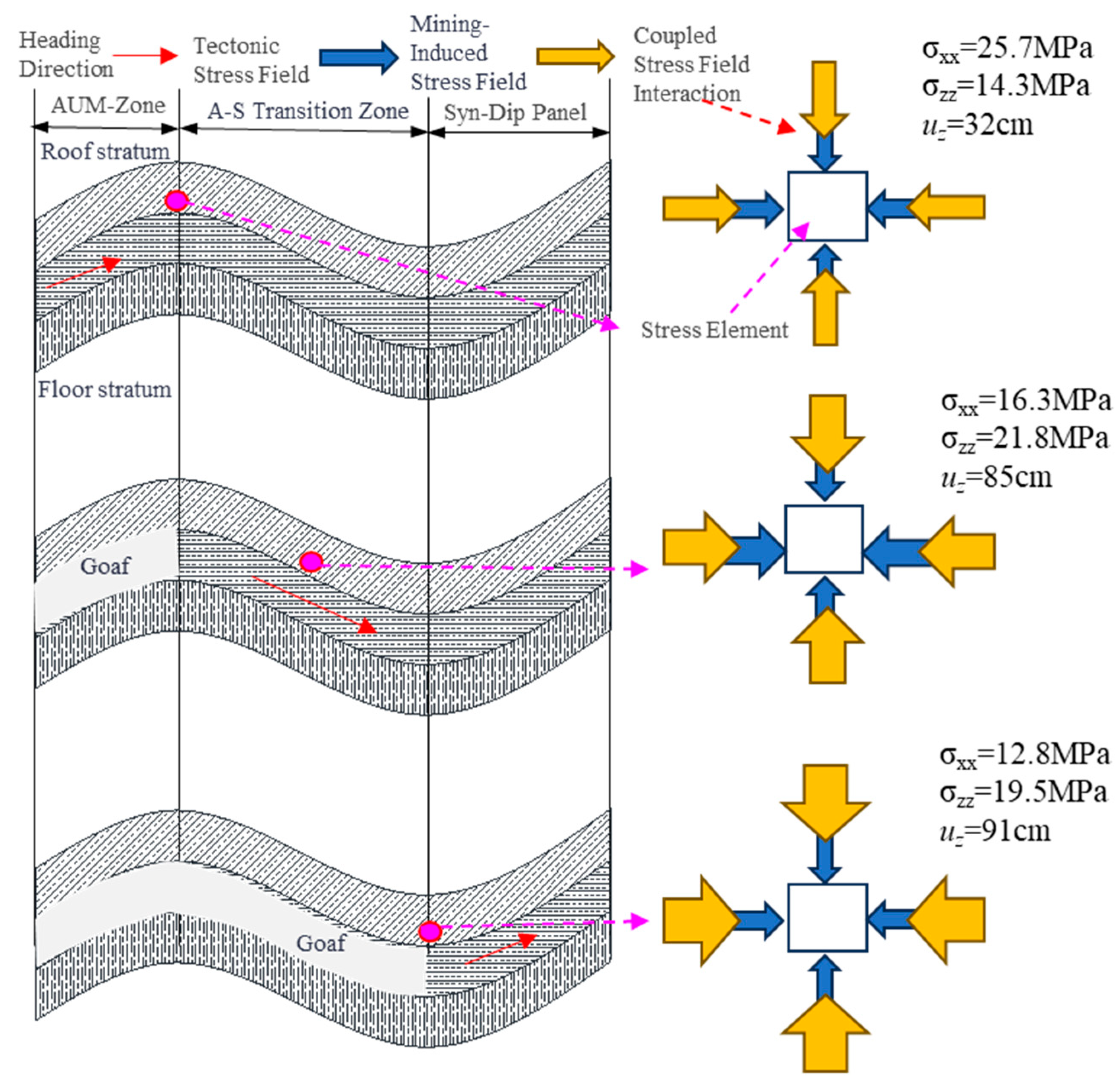
3.4. Stress Distribution Characteristics During Mining in the Current Working Face of Fold Structure Zones

The stress field during the mining of the current working face represents a further evolution based on the pre-mining stress field. Therefore, to investigate the dynamic evolution of the surrounding rock stress field during the mining process in the fold structure zone, the mining conditions of the current working face were simulated on the pre-mining model. A stress monitoring line was installed in the immediate roof of the coal seam at a position 20 m from the coal pillar. The stress distribution nephograms throughout the mining process and the dynamic evolution curves of stress at different advancing distances were extracted, as shown in Figure 10.
As illustrated, the mining process is divided into three distinct zones based on the distribution of fold structures and stress variations: the anticline mining zone, the anticline-syncline transition zone, and the syncline mining zone.
As shown in Figure 10a, in the anticline mining area, the horizontal stress ahead of the working face gradually increases as the face advances. Influenced by the superposition of fold structure-induced horizontal stress, the horizontal stress ahead of the working face reaches its peak value of 25.8 MPa when the face advances to the anticlinal axis. As the working face continues to advance and the gob area forms behind it, the vertical stress also peaks ahead of the working face. However, closer to the anticlinal axis, the vertical stress is released due to the fold structure, resulting in a reduced concentration of vertical stress in the roof ahead of the working face. When the face reaches the anticlinal axis, the peak vertical stress in the immediate roof ahead of the working face decreases to 14.3 MPa.
As shown in Figure 10b, in the anticline-syncline transition area, the horizontal stress ahead of the working face increases and then returns to the in situ stress state. Within the range from the anticlinal axis to the synclinal axis, the closer the working face is to the synclinal axis, the more pronounced the horizontal stress relief in the gob area due to the influence of the initial tectonic stress field. When the working face advances to 375 m from the setup entry, located at the synclinal axis, the horizontal stress ahead of the working face reaches its minimum value of 12.1 MPa in this region. As the gob area expands behind the working face, vertical stress concentration occurs ahead of the face, with the concentration increasing closer to the synclinal axis. When the working face advances to 300 m from the setup entry, the vertical stress reaches its peak value of 23.2 MPa.
As shown in Figure 10c, in the syncline mining area, the horizontal stress distribution trend is similar to that in the anticline mining area. The stress ahead of the working face initially increases and then decreases, with another increase in horizontal stress near the stopping line. The farther the working face is from the synclinal axis, the greater the horizontal stress concentration. When the working face advances to 500 m from the setup entry, the peak horizontal stress is 21.5 MPa. As the working face continues to advance, influenced by topographic conditions, the vertical stress in the surrounding rock gradually enters a relief zone. The farther the working face is from the syncline, the lower the vertical stress concentration ahead of the face. When the working face advances to 400 m from the setup entry, the maximum vertical stress is 22.6 MPa, and when it advances to 500 m, the vertical stress ahead of the face is 20.5 MPa.
In summary, the evolution of the mining-induced stress field in the current working face of the fold structure zone is jointly influenced by the initial fold structure stress and the mining-induced stress. The advancing position of the working face determines the location of stress concentration, while the fold structure stress controls the degree of stress concentration in different regions. Therefore, when the working face advances to the synclinal flanks, the stress in the roof of the gob area behind the face is released, and stress concentration ahead of the face increases significantly, leading to a higher risk of roof fracture and instability.

4. Evolution Patterns and Mechanism Analysis of Surrounding Rock Failure and Instability During Mining in Fold Structure Zones

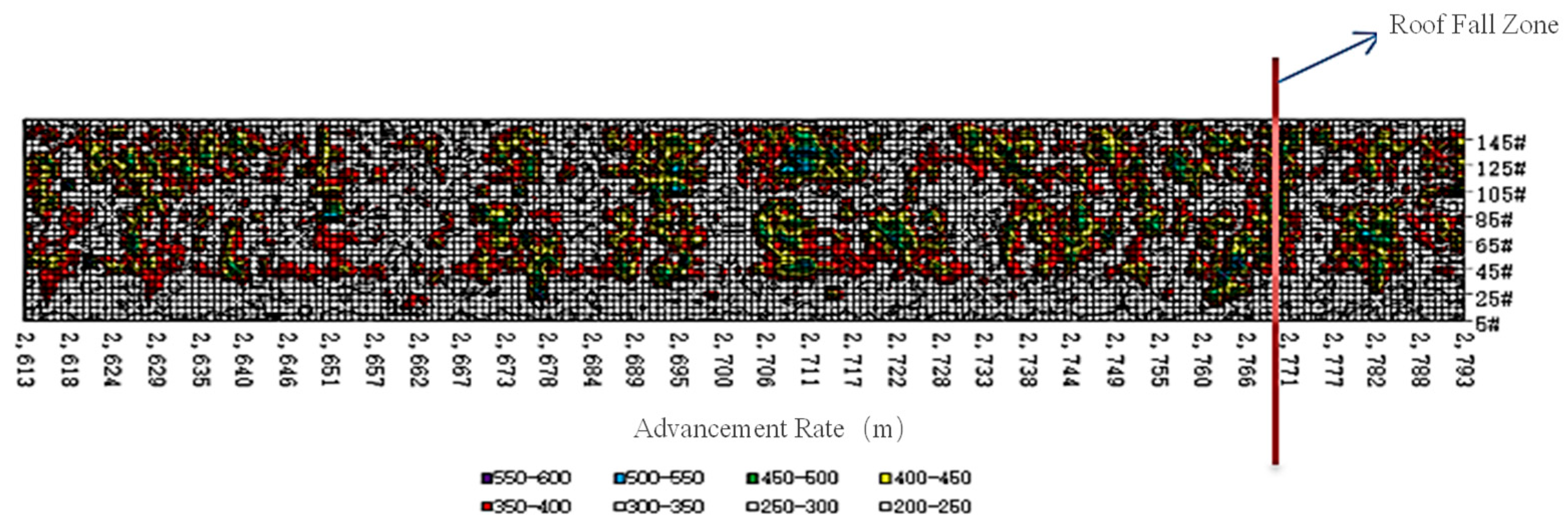
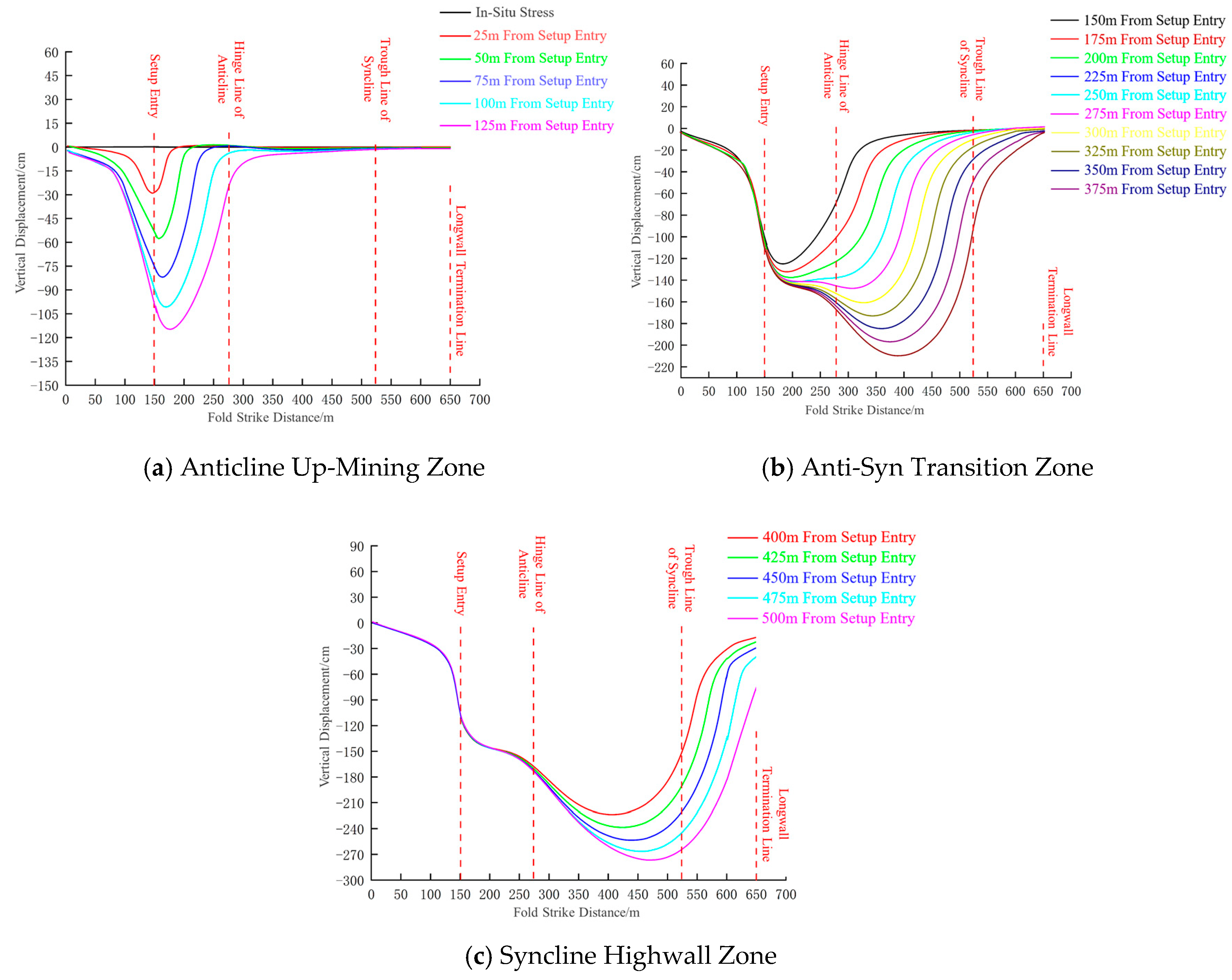
4.1. Evolution Patterns of Immediate Roof Displacement in Fold Structure Working Faces

Based on the stress distribution characteristics of the surrounding rock during mining in adjacent working faces within the fold structure zone, a displacement monitoring line was installed in the immediate roof of the coal seam at a position 20 m from the coal pillar. This setup was used to study the subsidence and instability process of the immediate roof in the current working face, revealing the evolution patterns of immediate roof displacement in the fold structure zone. The vertical displacement distribution curve is shown in Figure 11.
As shown in Figure 11a, in the anticline mining zone, the immediate roof of the working face remains stable with no displacement before excavation. As the working face advances and the gob area forms behind it, significant vertical displacement occurs in the immediate roof near the setup entry. The overall displacement curve exhibits an initial increase followed by a decrease between the setup entry and the advancing face, with no displacement occurring at the face itself. The closer the advancing distance is to the anticlinal axis, the more severe the subsidence of the immediate roof. When the working face advances to 125 m from the setup entry, the maximum vertical displacement in the gob area behind the face is 115 cm, while the maximum vertical displacement ahead of the face is 32 cm.
As shown in Figure 11b, when the working face advances into the anticline-syncline transition zone, the gob area behind the face continues to expand, and the immediate roof near the setup entry undergoes further subsidence. The farther the face advances, the greater the subsidence displacement in the gob area. After passing the anticlinal axis, influenced by the fold topography, the closer the face is to the synclinal axis, the greater the vertical stress, leading to further subsidence of the immediate roof in this region. The closer the face is to the synclinal axis, the more the overall displacement curve exhibits a bimodal distribution. When the working face advances to 375 m from the setup entry, the maximum vertical displacement in the roof of the gob area behind the face occurs near the synclinal axis, reaching 211 cm, while the vertical displacement ahead of the face is 118 cm.
As shown in Figure 11c, when the working face advances into the syncline mining zone, the overall displacement curve of the gob area follows a similar trend, exhibiting a bimodal distribution with peaks located ahead of the setup entry and behind the synclinal axis. The peak behind the synclinal axis is significantly larger than that near the setup entry. The farther the face advances, the greater the displacement peaks. When the working face advances to 500 m from the setup entry, the maximum vertical displacement in the gob area behind the face is 282 cm, while the vertical displacement ahead of the face decreases to 73 cm.
In summary, during the mining process of the current working face in the fold structure zone, the subsidence of the immediate roof in the gob area gradually increases as the working face advances. When the face is in the anticline mining zone, the influence of fold topography is minimal, and the maximum displacement of the immediate roof occurs ahead of the setup entry. After the face enters the anticline-syncline transition zone, the influence of fold topography becomes significant. The closer the face is to the synclinal axis, the subsidence of the immediate roof in the gob area exhibits a bimodal distribution, with the maximum subsidence occurring at the synclinal axis. Therefore, based on the evolution patterns of immediate roof displacement in the fold structure working face, the key areas for surrounding rock failure and instability during mining are the synclinal flanks of the fold structure zone.

4.2. Mechanism of Surrounding Rock Failure and Instability During Mining in Fold Structure Working Faces

The failure and instability of the working face during mining in the fold structure zone are directly related to the stress environment distribution characteristics under different mining conditions. Therefore, to further analyze the failure and instability characteristics at each mining stage, it is necessary to conduct an in-depth analysis of the relationship between the tectonic stress field and the mining-induced stress field. Figure 12 provides a schematic diagram illustrating the mechanism of surrounding rock failure and instability during mining in the fold structure working face.
As shown in Figure 12, the mining process in the fold structure zone exhibits zonal distribution, with the overall stress field being a superposition of the tectonic stress field and the mining-induced stress field. When the working face advances into the anticline mining zone, stress concentration occurs in the roof due to the generation of the advanced mining-induced stress field. However, influenced by the tectonic stress field, horizontal stress concentrates at the anticline, while vertical stress is in a relieved state, resulting in relatively small vertical displacement in this area. In this zone, the influence of the tectonic stress field outweighs that of the mining-induced stress field. When the working face advances into the anticline-syncline transition zone, the mining-induced stress gradually increases as the gob area behind the face expands. In this zone, the concentration of horizontal stress in the tectonic stress field intensifies, and vertical stress also increases with decreasing vertical distance, leading to a significant rise in vertical displacement. As the working face advances into the syncline zone, the gob area behind the face gradually collapses, and under the combined influence of the mining-induced and tectonic stress fields, vertical displacement further increases. Therefore, during the anticline-syncline transition and syncline mining stages, the mining end is significantly affected by the superposition of the tectonic and mining-induced stress fields, resulting in substantial roof displacement and an increased risk of roof collapse.
In summary, the mechanism of surrounding rock failure and instability during mining in the fold structure working face can be summarized as follows: the damage caused by mining is irreversible, and the stress field is influenced by the superposition of the tectonic and mining-induced stress fields. The extent of damage depends on the degree of stress concentration resulting from the superposition of these two fields at a given location. The degree of damage in different structural positions of the working face is directly related to the distribution of the fundamental tectonic stress field.

5. Surrounding Rock Control Technology for Mining in Fold Structure Zones

Based on the analysis of the surrounding rock stress field distribution characteristics during the entire mining process of adjacent working faces in fold structural zones, it is evident that the risk areas for roof fall accidents are primarily concentrated in regions of high fold structural stress, specifically at the transition phase of anticlines to synclines and the mining ends during the syncline uplift phase. Drawing from the engineering practices at the 12515 working face in the 5th panel of the Bulianta Coal Mine, this study proposes principles and strategies for controlling the surrounding rock to ensure the stability of the roof and roadway walls during the mining of fold structural zones, thereby facilitating efficient extraction in fully mechanized mining faces.

5.1. Principles of Surrounding Rock Control in Mining Faces Within Fold Structural Zones

In the high-stress-gradient fold flanks, the return air roadway of the 12515 working face is subjected to the combined effects of tectonic stress from the fold terrain, lateral stress from the goaf of the 12514 working face, and advanced mining-induced stress from the current working face, resulting in severe damage to the surrounding rock. To address this, a reinforcement support measure using anchor cables and steel straps was implemented for the roadway roof. The anchor cables were installed into the stable rock layer above the roof, allowing the cables and the anchored rock mass to jointly bear the load, thereby enhancing the support strength. Coupled with W-shaped steel straps, this approach effectively suppresses roof delamination, ensuring the integrity of the roadway roof, preventing roof collapse, and reducing mesh bagging phenomena.
Additionally, to improve the strength of the coal-rock mass, high-molecular chemical grout was uniformly injected into the weak structures of the coal-rock mass, such as pores, fractures, and joints, using hydraulic and pneumatic principles. The grout fills, penetrates, and compacts the coal-rock mass, binding it into a cohesive unit with high strength, excellent anti-seepage properties, and enhanced stability. This improves the physical and mechanical properties of the coal-rock mass, increasing its integrity and strength, thereby mitigating roof leakage, collapse, and coal wall spalling to a certain extent.
During mining through fold flanks, the roof pressure on the working face can be significant, especially when the roof rock beams fracture parallelly, leading to intense pressure that may trigger roof falls or even crush the supports. Hydraulic supports, as the primary equipment ensuring mining space height, divide the stope into the goaf and the controlled roof area. Increasing the working resistance of hydraulic supports can control roof subsidence in high-mining-intensity faces, but blindly increasing support resistance often yields limited results. Therefore, adopting pressure control technologies in both the controlled roof area and the goaf can effectively mitigate the impact of periodic weighting on the supports, ensuring the safety of the stope space and the stability of the surrounding rock structure.
In summary, to address the challenges of roof and surrounding rock control in working faces affected by intense mining in fold structures, a coordinated control scheme is proposed. This includes pressure control technologies in the controlled roof area and goaf, high-molecular chemical grouting reinforcement, and reinforced support for the roadway roof. This approach leverages the synergistic advantages of the “working face-support” and “roadway-support” structures to ensure the stability of the surrounding rock and the safe, efficient production of the working face during mining through fold structures.

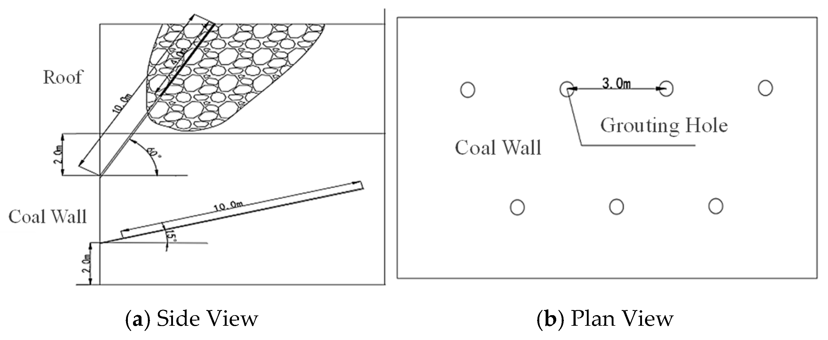
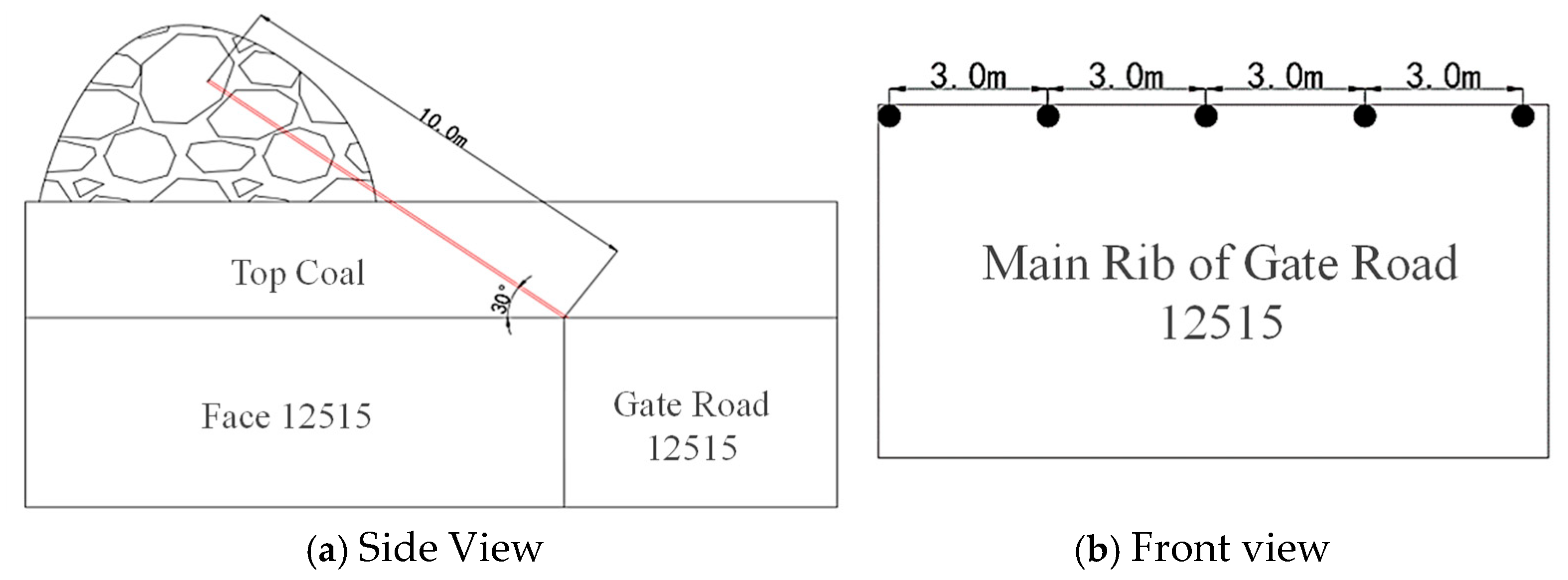
5.2. Surrounding Rock Control Strategy for Roadways in Fold Structural Zones

To ensure safe production in the working face, pre-grouting reinforcement should be implemented in the transition zone of the anticline and the flanks of the syncline, as well as within a 20-m range before and after these areas. This measure aims to further control roof falls and rib spalling. Specifically, when the working face advances beyond the anticlinal axis and reaches the flanks of the syncline, grouting reinforcement should be applied to both the roof and the coal wall side.
For areas severely affected by folding, where the roof is fractured and rib spalling is prominent, a combination of roof grouting, fiberglass bolt reinforcement, and coal wall grouting should be adopted. Two rows of grouting holes are arranged on the coal wall of the working face. The first row of grouting holes is positioned 2.0 m below the roof, with holes drilled at an angle of 60–70° upward from the horizontal direction. The depth of these holes should be no less than 10 m, with a spacing of 3 m between holes. After drilling, fiberglass bolts with a diameter of 18 mm and a length of 4 m are inserted into the grouting holes, followed by the injection of high-molecular materials for reinforcement. The second row of grouting holes is positioned 2.0 m above the floor, with holes drilled at a 15° upward angle from the horizontal direction. The depth of these holes should also be no less than 10 m, with a spacing of 3 m. Detailed parameters of the grouting hole arrangement are shown in Figure 13.
When the specific area is located at the headgate or tailgate region, high molecular materials are injected from the solid side of the roadway towards the roof side of the working face within one entry. Boreholes are drilled at the intersection of the roof and the solid side, inclined upwards at a 30° angle to the horizontal, with a depth of no less than 10 m and spaced 3 m apart. The construction plan, including borehole location, depth, and angle, can be adjusted based on field conditions. The layout of the grouting holes is illustrated in Figure 14.
Within the range from the open-off cut to the anticlinal axis, the stress gradient exhibits minimal variation, with low stress concentration and vertical displacement. In this region, the original roadway support scheme is maintained. In the transition zone between the anticline and syncline, where the stress gradient is significant, and within the syncline’s uplifted fold limb, additional reinforcement measures are implemented for the extraction roadway. Roof support is enhanced using Φ20.8 × 5150 mm anchor cables combined with steel straps. Solid wooden cribs are erected in the entry crosscuts to support the roof, and ventilation barriers are installed at the crosscut entrances. Within the fold limb area, one row of two Φ21.6 × 5150 mm anchor cables with 1500 × 300 × 12 mm PVC straps is installed at 3.0 m intervals to prevent rib spalling. Based on field conditions, if the roof-to-canopy distance at the working face is large (exceeding 1.0 m after extending the canopy) and the roof remains relatively intact, Φ20.8 × 5150 mm anchor cables are used to reinforce the roof in the gaps between supports and the unsupported areas ahead of the canopy. This prevents roof failure and collapse due to inadequate support in areas with large canopy-to-roof distances (the specific locations for anchor cable installation are determined based on actual conditions). The roadway support cross-section is illustrated in Figure 15.
Based on the aforementioned research findings and the practical production conditions of the 12515 working face, the proposed ground control strategy was implemented on-site. During the mining process through the fold structure zone, the surrounding rock of the 12515 working face remained stable and secure, with no incidents of roof collapse or rib spalling occurring.

6. Conclusions

(1) The pre-mining stress field in fold structure zones is characterized by significant horizontal stress influenced by the structure, with stress concentration locations remaining consistent before and after mining. Post mining, the horizontal stress in the syncline axis and its flanks is gradually released. Vertical stress is more affected by mining activities; after mining, internal stress is released, and stress concentration is evident at the syncline axis and its flanks. The stress concentration at the anticline axis is less pronounced due to structural influences.
(2) The evolution of the mining-induced stress field in fold structure zones is jointly influenced by the initial tectonic stress and mining-induced stress. The advancing position of the working face determines the stress concentration locations, while the tectonic stress controls the degree of stress concentration in different regions. As the working face advances into the syncline flanks, stress is released in the goaf behind the face, and stress concentration increases ahead of the face, significantly raising the risk of roof failure.
(3) The mechanism of surrounding rock failure and instability in fold structure zones is irreversible, with the stress field being a superposition of tectonic and mining-induced stresses. The degree of failure depends on the combined stress concentration at specific locations, directly related to the distribution of the initial tectonic stress field.
(4) For the control of roof and surrounding rock in roadways under strong mining influence, a coordinated control strategy was developed, incorporating roof pressure control, goaf pressure control, polymer chemical grouting reinforcement, and supplementary roof support in roadways. Application of this strategy in the 12515 working face ensured the stability of surrounding rock during mining through fold structure zones, with no incidents of roof collapse or rib spalling.

Author Contributions

Software, R.W. and H.Z.; Investigation, H.L.; Data curation, S.Y.; Writing—original draft, J.W. and G.L.; Writing—review and editing, W.W. All authors have read and agreed to the published version of the manuscript.

Funding

This research was supported by the National Natural Science Foundation of China (Grant No. U24A2085, 52264010), Natural Science Foundation of Inner Mongolia (Grant No. 2024LHMS05017), Inner Mongolia Autonomous Region First-class Discipline Scientific Research Special Program (Grant No. YLXKZX-NKD-036), Development Project of Young Scientific and technological talents in Inner Mongolia Autonomous region (Grant No. NJYT23065) and Inner Mongolia Autonomous Region Directly-Affiliated Universities Basic Scientific Research Operating Funds Program (Grant No. 2023CXPT003, 2023QNJS096).

Data Availability Statement

The original contributions presented in this study are included in the article. Further inquiries can be directed to the corresponding author.

Conflicts of Interest

The author Gao Li was employed by China Energy Trading Group Co., Ltd. The author Hu Liu was employed by Sunsangou Coal Mine of Inner Mongolia Hongyuan Coal Group Co., Ltd. The remaining authors declare that the research was conducted in the absence of any commercial or financial relationships that could be construed as a potential conflict of interest.

References

  1. Wang, L.; Cao, A.; Guo, W.; Dou, L.; Wen, Y.; Xue, C.; Hu, Y.; Lv, D. Rock burst mechanism and characteristics of roadway in “fault-fold” area. J. Min. Saf. Struct. Eng. 2023, 40, 69–81+90. [Google Scholar]
  2. Kang, H.; Wu, Z.; Gao, F.; Ju, W. Effect of geological structures on in-situ stress distribution in underground coal mines. Chin. J. Rock Mech. Eng. 2012, 31 (Suppl. S1), 2674–2680. [Google Scholar]
  3. Wang, H.; Deng, D.; Jang, C.; Shi, R.; Yan, X. Study on evolution characteristics of uneven stress field in mining induced fold tectonic area. Coal Sci. Technol. 2020, 48, 59–69. [Google Scholar]
  4. Hu, G.-D.; Cui, H.-Q.; Guan, J. Numerical simulation of stress distribution in small foldof coal seam. J. Saf. Environ. 2016, 16, 54–57. [Google Scholar]
  5. He, H.; Dou, L.; Gong, S.; Zhou, P.; Xue, Z.; Jiang, H. Research on Seismicity in High Tectonic Stress Zones. J. China Univ. Min. Technol. 2011, 40, 7–13. [Google Scholar]
  6. Wang, C.; Jiang, F.; Liu, J. The Controlling Effect of Structures on Rockburst and Case Analysis. J. China Coal Soc. 2012, 37 (Suppl. S2), 263–268. [Google Scholar]
  7. Wang, Z.; Kang, H.; Lin, J. Research on the Influence of Folded Structure Stress on Roadway Support. Coal Sci. Technol. 2011, 39, 25–28. [Google Scholar]
  8. Jing, G. Research on Stress Evolution and Rockburst Incubation in Thick Coal Seam Mining in Folded Structure Zones. Master’s Thesis, China University of Mining and Technology, Xuzhou, China, 2017. [Google Scholar]
  9. Chen, G. The Mechanism of the Effect of Maximum Horizontal Stress on Rockburst and Its Application. Ph.D. Thesis, China University of Mining and Technology, Xuzhou, China, 2009. [Google Scholar]
  10. Wang, S.; Zhang, X. The Relationship Between Geological Structures and Stress in Coal Mine Roadways. J. China Coal Soc. 2008, 33, 738–742. [Google Scholar]
  11. Guo, C.; Zhang YJiang, L.; Sun, D.; Xiong, T.; Du, Y.; Zheng, G. Rockburst Mechanism and Suitable Tunnel Section in Deep-Buried Tunnels in Folded Structures. Chin. J. Rock Mech. Eng. 2012, 31 (Suppl. S1), 2758–2766. [Google Scholar]
  12. Shi, Q.; Pan, Y.; Li, Y. Typical Cases of Rockburst in China and Analysis. Coal Min. 2005, 10, 13–17. [Google Scholar]
  13. Zhou, Y.; Lin, G.; Gong, F.; Liu, S.; Zhang, D. Changes in the Maximum Principal Stress and Horizontal Strain During the Deformation of a Single Fold and Influencing Factors. Geotecton. Metallog. 2007, 31, 37–43. [Google Scholar]
  14. Wang, J. The Impact of Folds and Flexures on Coal Seam Mining in Yangmei No. 5 Mine. Coal Min. 2015, 20, 20–22. [Google Scholar]
  15. Cao, A.; Xue, C.; Wu, Y.; Wang, S.; Guo, W. Mechanism and Prevention of Rockburst in Coal Mining in Folded Structure Zones. Coal Sci. Technol. 2021, 49, 82–87. [Google Scholar]
  16. Chen, M. The Impact of Folded Structures on Coal Seam Mining. Inn. Mong. Coal Econ. 2017, 10, 5–6. [Google Scholar]
  17. Wu, Y. Research on the Stress Field Distribution and Evolution of Overburden Spatial Structure in Folded Structure Zones. Master’s Thesis, China University of Mining and Technology, Xuzhou, China, 2018. [Google Scholar]
  18. Bu, W.; Xu, H.; Zhao, Y. Analysis of Overburden Deformation and Stress in Folded Structures Based on Curved Beam Theory. J. Min. Saf. Eng. 2019, 36, 827–833. [Google Scholar]
  19. Liu, B.; Li, X.; Xie, C. Numerical Experimental Analysis of Coal Mining Subsidence in Folded Structure Zones. Jiangxi Coal Sci. Technol. 2016, 3, 12–15. [Google Scholar]
  20. Tian, C.; Yang, Z.; Li, G. Three-Dimensional Similarity Simulation of Mining Pressure in Large-Height Working Faces in Folded Structure Zones. J. Heilongjiang Univ. Sci. Technol. 2023, 33, 861–868. [Google Scholar]
  21. Tang, L.; Tu, S.; Tu, H.; Zhang, L.; Li, W.; Miao, K.; Zhao, H.; Ma, J. Mining stress evolution law and control technology of surrounding rock in fold structure area. J. Min. Saf. Eng. 2024, 1–11. Available online: http://kns.cnki.net/kcms/detail/32.1760.TD.20240412.1751.002.html (accessed on 5 May 2025).
  22. Lu, C.; Zhang, X.; Xiao, Z.; Wang, C.; Wang, B.; Zhou, T.; Li, H.; He, Z. Study on controlling law of fold structure on evolution of mining stress in deep mines. Coal Sci. Technol. 2020, 48, 44–50. [Google Scholar]
Figure 1. Geological Overview of Face 12515.
Processes 13 01534 g001
Figure 2. Borehole Camera Observation Points.
Processes 13 01534 g002
Figure 3. Borehole Digital Imaging.
Processes 13 01534 g003
Figure 4. Strata Pressure Distribution Map Across Fold Zone in Face 12514.
Processes 13 01534 g004
Figure 5. Monitoring results of periodic weighting.
Processes 13 01534 g005
Figure 6. Numerical Computation Model.
Processes 13 01534 g006
Figure 7. Boundary Load Application Methods in Numerical Models.
Processes 13 01534 g007
Figure 8. Initial Stress Contour Map in Folded Zone.
Processes 13 01534 g008
Figure 9. Surrounding Rock Stress Contour Map Near Gob Areas in Folded Zones.
Processes 13 01534 g009
Figure 10. Characteristic Stress Distribution Diagrams During Full-Seam Mining in Folded Zones.
Processes 13 01534 g010aProcesses 13 01534 g010b
Figure 11. Roof Vertical Displacement in Fold Structure Zone (Face 12515).
Processes 13 01534 g011
Figure 12. Schematic Diagram of Surrounding Rock Failure Mechanisms in Longwall Mining Through Fold Structures. (AUM = Anticline Up-Mining, A-S = Anticlinal-Synclinal, Syn-Dip = Syncline + Dip).
Processes 13 01534 g012
Figure 13. Grouting Borehole Layout Schematic in the Working Face.
Processes 13 01534 g013
Figure 14. Schematic Layout of Grouting Holes in Stope Drift.
Processes 13 01534 g014
Figure 15. Cross-Sectional View of Roadway Support Structure.
Processes 13 01534 g015
Table 1. Rock mass mechanical properties.
Name of StratumThe Angle of Internal Friction/(°)Shear Modulus of Elasticity/GPaBulk Modulus/GPaCohesion/MPaTensile Strength/MPaDensity Kg/m−3
Siltstone388.110.83.53.202480
Fine Sandstone4213.518.015.33.502490
Sandy Mudstone291.72.32.01.302350
Gritstone342.94.25.01.902560
Coal261.51.81.31.221930
Disclaimer/Publisher’s Note: The statements, opinions and data contained in all publications are solely those of the individual author(s) and contributor(s) and not of MDPI and/or the editor(s). MDPI and/or the editor(s) disclaim responsibility for any injury to people or property resulting from any ideas, methods, instructions or products referred to in the content.

