Abstract
This paper proposes a design and control process for a dual-phase motors (DPM) aimed at independent drive. To achieve independent drive, different pole numbers are used for the inner rotor and outer rotor of the dual-rotor motors (DRM). Additionally, a special winding method is selected to allow the inner rotor and outer rotor to operate independently on a single stator. Through this winding method, only the rotor linked to the current is driven. The motor uses a combined current synthesized from 3-phase and 6-phase currents, and so the current ratio and period based on electrical frequency are determined. By selecting the current ratio, a current similar to the phase voltage waveform is formed to find the optimal output point, which is then formalized. Furthermore, by redefining the period, the inner rotor and outer rotor are analyzed separately within the complex waveform. Subsequently, the motor’s T-N curve characteristics are analyzed through voltage/current limit circles, and the control method is explained to present the overall process of the DPM.
1. Introduction
Recent efforts to tackle climate change and achieve carbon neutrality have involved setting greenhouse gas reduction targets. One of these efforts is accelerating the transition from internal combustion engine vehicles to zero-emission vehicles by promoting the adoption of electric vehicles. As interest in electric vehicle adoption grows, the development of traction motor technology, which is the driving system for electric vehicles, is also actively progressing. The traction motor must be designed by considering both the rated speed and high speed. Additionally, due to the characteristics of electric vehicles, a high power density is also an important factor. To achieve a high power density, permanent magnet synchronous motors (PMSM) are commonly used [1,2,3,4,5]. PMSM use permanent magnets to achieve a high air gap flux density. They have excellent high-power density characteristics. However, they are expensive because they require permanent magnets that are rare earth materials. PMSM can be categorized into radial flux motors (RFM) and axial flux motors (AFM). In RFM, the flux lines are formed in the radial direction, whereas in AFM, the flux lines are formed in the axial direction. Recently, research on AFM as PMSM for traction motor applications has become more active [6,7]. The reason for the increased research on AFM is that they can achieve a higher power density compared to the same volume [8,9]. This is because the output of RFM is proportional to the square of the diameter, while the output of AFM is proportional to the cube of the diameter, resulting in a difference in output for the same volume. However, AFM have disadvantages. Due to structural reasons, AFM require multiple poles. As the number of poles increases, the electrical frequency increases proportionally for the same speed, which results in increased losses. Various studies are being conducted to reduce this issue. For example, in [10], a quasi-3D calculation and an analytical approach using magnetic equivalent circuits were proposed to analyze iron losses in AFM. Additionally, the research in [11] analyzed eddy current loss based on AFM materials, concluding that electrical steel sheets are more advantageous than soft magnetic composite (SMC) cores. AFM are also at a disadvantage in mass production compared to RFM. The structure that involves rolling and laminating steel sheets is challenging to manufacture, and the structure that uses powder cores faces performance degradation due to magnetic saturation and manufacturing difficulties compared to structures using soft magnetic materials. On the other hand, RFM are advantageous for mass production due to their structural characteristics, which allow for the lamination of soft magnetic steel sheets of the same shape. Stability in motor operation is also one of the important factors. Recent research is being conducted on multiphase motors [12,13]. Among multiphase motors, those with phases that are multiples of three are gaining more attention for applications where safety is crucial (in the space, traction, and military sectors). This is because they can continue to operate safely even if one phase fails. Further research on high-power-density motors using RFM, which offer advantages in terms of losses and mass production, must be conducted. To increase the power density using RFM, the topology is examined using a dual-rotor RFM, which employs two rotors on a single stator. Conventional dual-rotor motors (DRM ) utilize a single stator and two rotors, enabling the use of more permanent magnets to achieve a high power density. In terms of the driving method, both the inner and outer rotors operate simultaneously. Through further research to enhance the power density in this configuration, the newly introduced dual-phase motors (DPM), which enables the independent operation of both the inner rotor and outer rotor in a DRM, requires careful consideration of its design process. In the case of a DPM, one rotor linked to the 3-phase current and the other rotor linked to the 6-phase current are shared on a single stator. As a result, the inner rotor and outer rotor of a single motor are independently driven. When using two phases for independent drive, analyzing the mutual interference and the ratio is necessary. Additionally, since the resulting data are expressed as a composite waveform, a method for data analysis is required. In the case of PMSM, there is a voltage limit imposed by the inverter [14,15]. When the speed increases beyond the base RPM, the voltage limit is exceeded, necessitating field weakening control, which reduces torque. Since the DPM allows for independent drive, it also enables independent control. Independent control increases the range of field weakening control options, thereby diversifying the operating range. In other words, if independent control is possible according to the current ratio and type of current, the range of torque options in the high-speed region increases. This paper selects the DPM among RFM structural configurations to achieve a high power density. It explains the geometric design methodology to obtain optimal torque in the DPM, analyzes complex simulation data arising from differing pole pairs in the inner and outer rotors, proposes control strategies, and outlines the comprehensive design process for the DPM. This paper’s structure is as follows: Section 2 explains the driving theory for independent drive of the DPM, describing the structural characteristics of the DPM and proposing a winding connection method for independent drive. Section 3 explains the characteristics that occur when applying a combination of the 3-phase current and 6-phase current. It defines the magnitude and period that appear in the synthesis of sinusoidal waves and selects the current ratio through FEA (Finite Element Analysis) data of the DPM. Subsequently, it proposes a formula for the period of sinusoidal waves with different frequencies to determine a more accurate current ratio and formalizes this. Section 4 modifies the rated speed and high speed due to the increased voltage margin resulting from period selection. It demonstrates the motor’s characteristics according to current ratios through voltage/current limit circles and presents the motor’s operating characteristics at different speeds using T-N curves. Additionally, it proposes a control topology for dual-current phase angle control.
2. Definition and Design Process of the DPM
2.1. Definition of a DPM
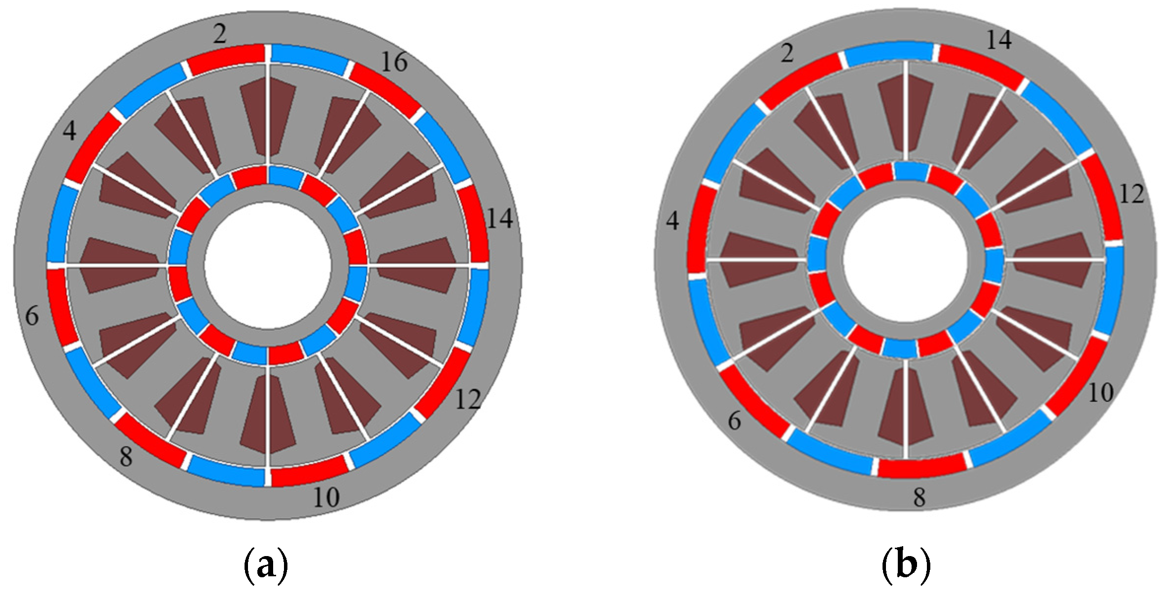
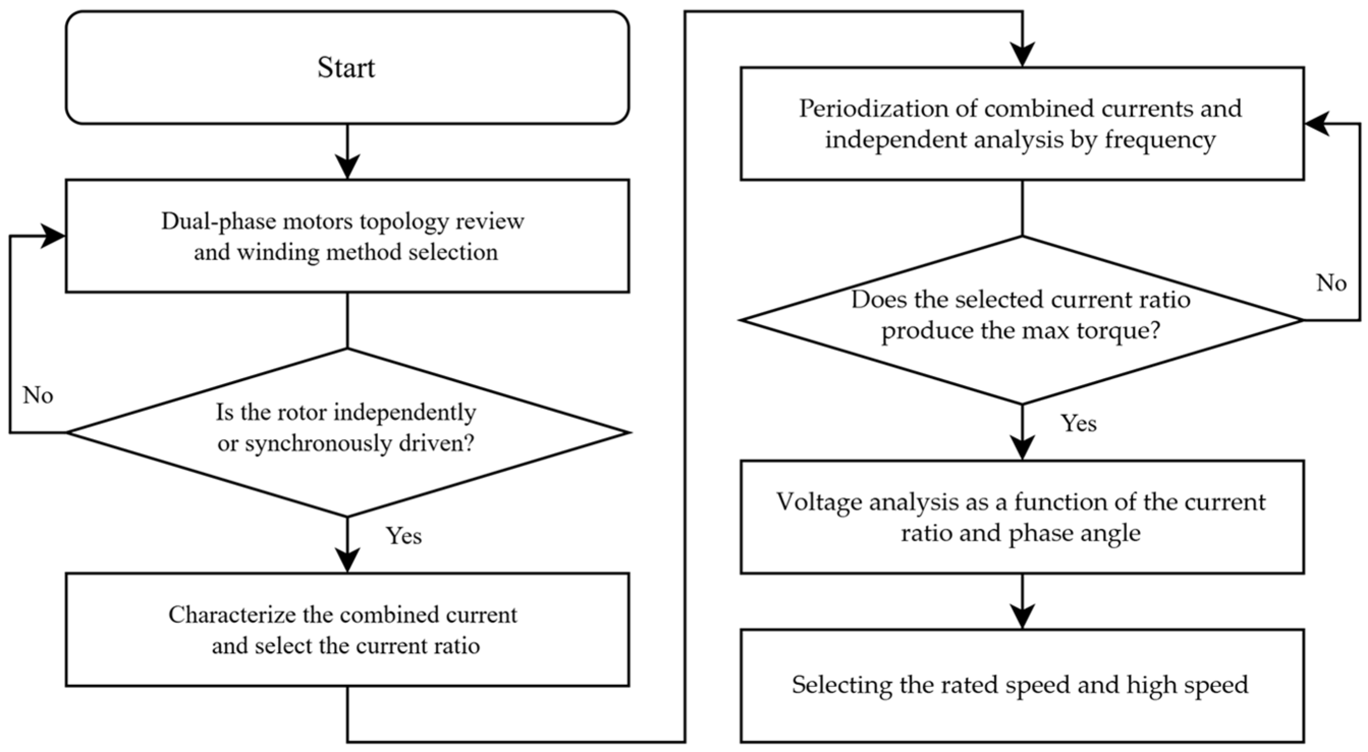
A DRM is a structure in which both an inner rotating motor and an outer rotating motor are incorporated into a single motor. In conventional DRM, when current is applied, the inner rotor and outer rotor drive simultaneously. While the proposed DPM has one rotor linked with a 3-phase current and another rotor linked with a 6-phase current. As a result, each rotor drives only when its linked phase is applied. To achieve independent drive, a special combination of poles and slots must be satisfied. As shown in Figure 1a, the DRM has the same number of poles for the inner rotor and outer rotor. This means that the inner rotor and outer rotor have the same winding factor at the stator. Therefore, only simultaneous drive is possible. However, as seen in Figure 1b, the DPM has different numbers of poles for the inner rotor and outer rotor. As a result, the two rotors have different winding factors, giving them the potential for independent drive. To enable independent operation of the motor, a different winding method from conventional approaches must be applied to find combinations that result in a winding factor of zero. More detailed information on the output strength according to the number of poles and slots is provided in Section 2.3. The DPM proposes independent drive by utilizing the characteristics of a 6-phase motor and the fact that inner rotor–stator and outer rotor–stator can have different winding factors. To design the DPM, we proceed as shown in Figure 2.
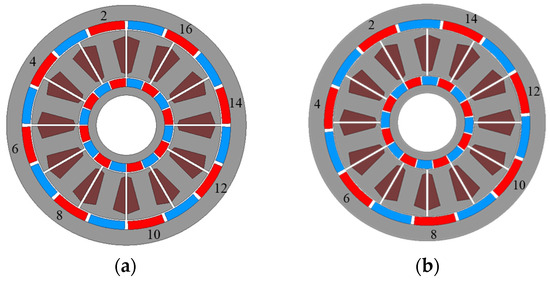
Figure 1.
Dual-rotor motors design based on the number of poles for the inner and outer rotors. (a) Inner-16-pole/12-slot/outer-16-pole motor design and (b) inner-16-pole/12-slot/outer-14-pole motor design.
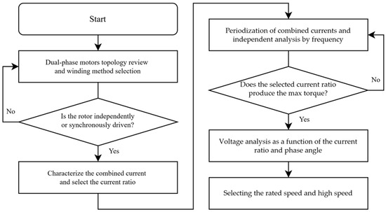
Figure 2.
DPM design process.
2.2. Phase Difference of the 6-Phase Current
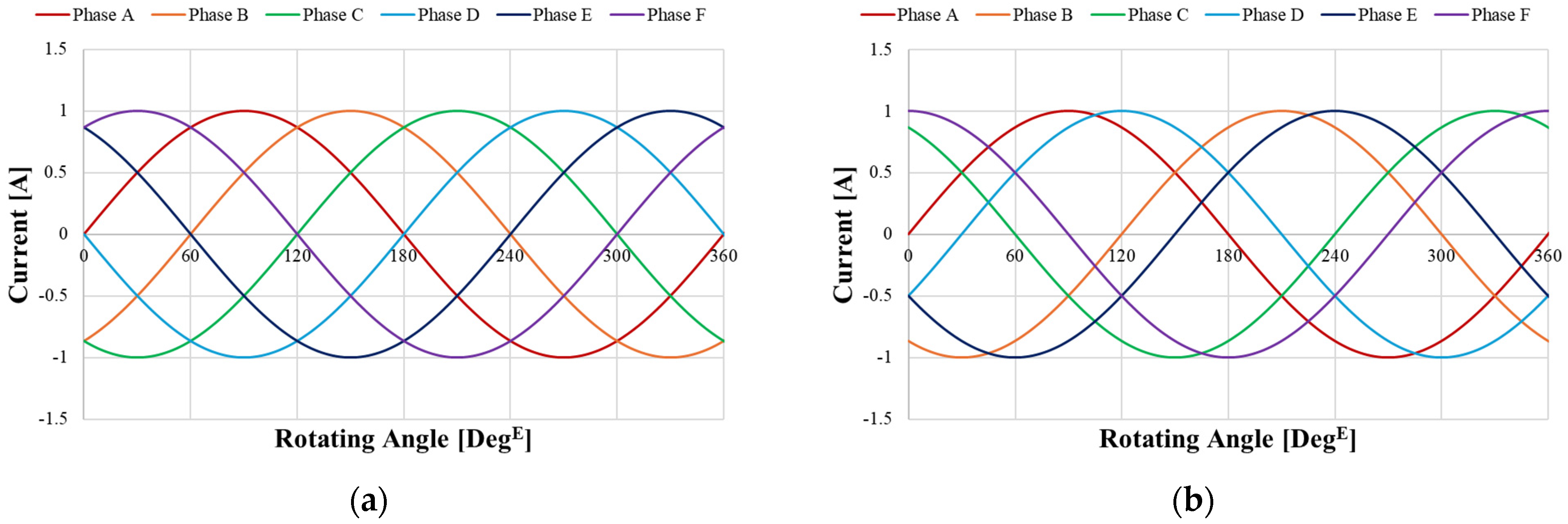
To achieve independent drive, the method of applying a 6-phase current must be determined. Figure 3 explains the 6-phase current. It is a peak current with a magnitude of one and a period of 360 degE (electrical degree). Figure 3a shows the case where each phase of the 6-phase current has a 60 degE difference. This case is called the symmetry phase difference. Like applying current to a conventional 3-phase motor, each phase has the same phase difference, maintaining equal intervals both spatially and temporally. Figure 3b, unlike Figure 3a, is called the asymmetry phase difference.
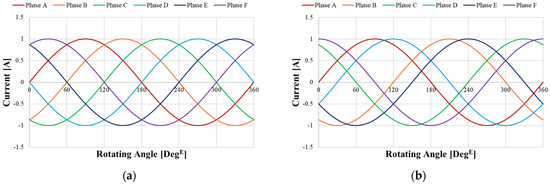
Figure 3.
Input current waveforms of phases A to F in a 6-phase motor. (a) 6-phase currents with a 60 electrical degree symmetry phase difference and (b) 6-phase currents with 30 and 120 electrical degree asymmetry phase differences.
A 6-phase motor driven with asymmetric currents, as shown in Figure 3b, operates like two 3-phase motors with a 30 degE phase difference. This allows the motor to continue stable operation even if one of the phases A–F fails. From the inverter’s perspective, there are also differences when comparing Figure 3a,b. A 3-phase inverter typically uses a combination of six switching elements to control the 3-phase of the motor. Each phase is connected to two switching elements, and the direction of the phase current is controlled depending on whether the top or bottom switching element is turned on. The switching functions S1, S2, and S3 apply square waves with a 120 degE phase difference to the switching elements. Following the same principle, a 6-phase system uses twelve switching elements. In Figure 3a, the switching functions S1, S2, S4, S5, and S6 apply square waves with a 60 degE phase difference to the switching elements. In Figure 3b, it is divided into Set 1 and Set 2. In Set 1, S1, S2, and S3 are designed to have a 120 degE phase difference, and in Set 2, S4, S5, and S6 also have a 120 degE phase difference. Then, Set 1 and Set 2 are arranged to have a 30 degE phase difference between them, resulting in the configuration shown in Figure 3b. This paper ultimately aims to use both the 3-phase and 6-phase configurations in a single motor. Therefore, a 6-phase motor driven with symmetric currents, as shown in Figure 3a, will be used. The reason for this is that all phases have a 60 degE phase difference. By simply applying reverse-direction currents to phases B, D, and F, they become identical to phases A, E, and C, respectively, effectively transforming the motor into a 3-phase motor. Based on the potentials discussed in Section 2.1 and Section 2.2, Section 2.3 will propose a special combination that enables independent drive.
2.3. Winding Connection Method That Enables Independent Drive
2.3.1. Basic Explanation of the Winding Factor
Before starting Section 2.3, this paper will henceforth express the number of poles as pole pairs; so 14-pole will be denoted as 7-pole, and 16-pole as 18-pole. To enable independent drive, finding the right combination of the inner pole, stator slot, and outer pole is necessary. The key point is that the same stator slot is used. Therefore, finding a related combination of the inner pole, stator slot, and outer pole is needed. For conventional PMSM, when determining the winding method through the combination of poles and slots, many researchers use established winding methods such as the Miller and Hanselman method. This paper uses the star of slot method. This method finds the combination that maximizes the winding factor, resulting in high torque. When using the star of slot method to determine the winding method for DPM, it needs two stators due to the different numbers of poles between the inner pole and outer pole. Moreover, when designing the motor and applying current using the selected winding method, independent drive is not achieved. Since independent operation is crucial for DPM, the winding method is not primarily focused on achieving a winding factor close to one for high torque, as is the case with conventional winding methods. In DPM, even if the winding factor is small, one of the two rotors should have a winding factor of zero in a single winding method. To achieve independent drive, the pole and current phases must be linked in a one by one. Also, the winding factor of the pole not linked to the current phase should be zero. The motor output is influenced by the MMF (Magnetomotive Force). The flux linkage is affected by the flux from the permanent magnet and the flux formed by passing alternating current through the armature winding. The flux linkage of the armature winding varies in MMF strength and sinusoidal degree, depending on the winding method. To compare this numerically, formulas are introduced. The first is the distribution factor. The distribution factor, Kd, can be defined as in Equation (1) according to Figure 4a. It is calculated using 15 slots as an example. The ratio of the scalar value obtained by adding only the magnitudes of the linked flux sum and the vector value obtained by adding the magnitudes and directions is shown in Equation (1). It is the ratio of the total length of the blue solid line to the total length of the red dotted line in Figure 4a. The second is the pitch factor. The pitch factor, Kp, indicates how much to turn of the coil winding occupy based on one pole of the permanent magnet. As shown in Figure 4b, when one pole of the permanent magnet is set to π, it represents the proportion of the winding occupying βπ. This can be expressed using Equation (2).
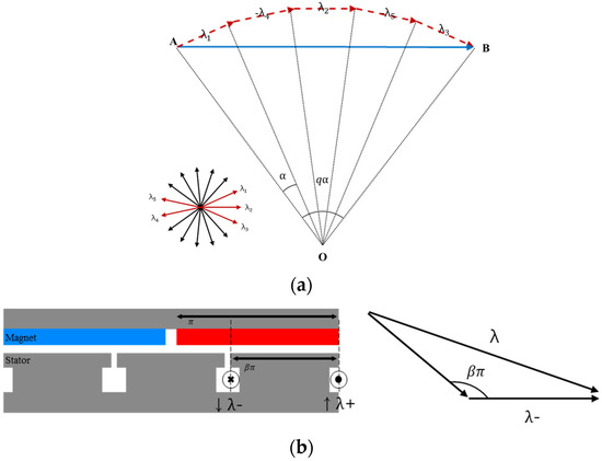
Figure 4.
Phasor concept diagram for explaining the winding factor. (a) Phasor diagram representing the distribution factor. (b) Phasor diagram and figure representing the pitch factor.
2.3.2. Selection of the Winding Method for the Independent Operation of the Inner Rotor and Outer Rotor
The winding factor is composed of the product of the distribution factor (Kd), pitch factor (Kp), and skew factor (Ks). Skew is not applied, and so Ks = 1. Therefore, the winding factor of the DPM is assumed to be as shown in Equation (3). To achieve a winding factor of zero, either the distribution factor or the pitch factor must be zero. However, it is impossible for the pitch factor to be zero when the coil span is one or greater in the relationship between pole and slot. Therefore, we need to find a combination where the distribution factor becomes zero. Table 1 shows the situations that satisfy this condition. The combination that can make the distribution factor zero is 8-pole, 7-pole, and 6-slot. In this case, the pitch factor is as shown in Figure 5. Since only even numbers are possible for poles, 16-pole, 14-pole, and 12 slots were selected. As shown in Table 1, when we find the point where the distribution factor becomes zero, the winding factor also becomes zero. This means that torque is not generated even when current is applied. Table 1 show that 7-pole are linked to 3-phase, and 8-pole are linked to 6-phase. The winding factor for the 7-pole–3-phase system is 0.94, while that for the 8-pole–6-phase system is 0.75.

Table 1.
Winding factor combinations capable of independent operation among the 6:7:8 pole–slot combinations.
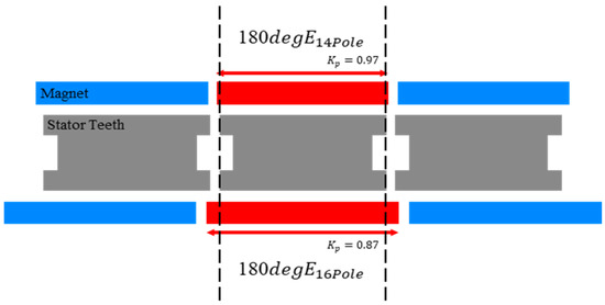
Figure 5.
Pitch factor of 6:7:8 pole–slot combinations.
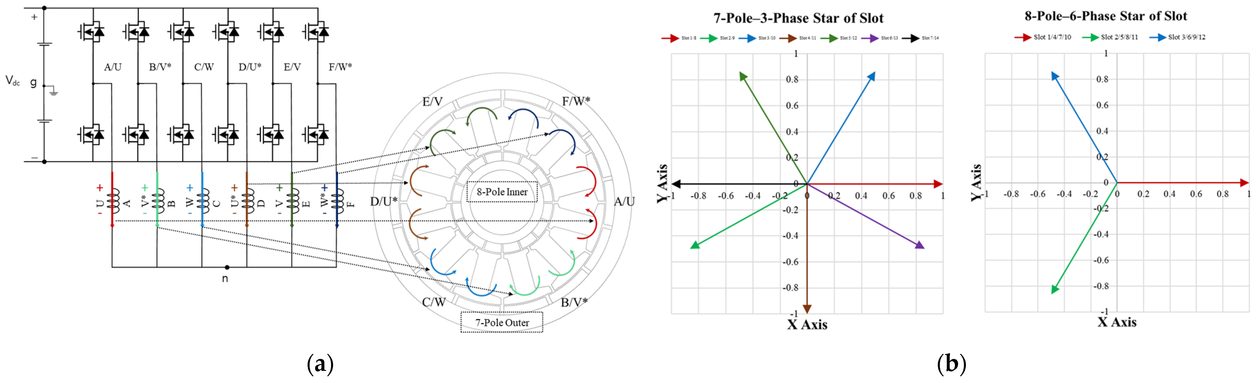
Using the 7-pole–3-phase configuration, which can create a larger MMF, on the outer rotor that uses more magnets allows for higher torque. Therefore, the DPM configuration is selected as 16-pole–6-phase inner rotor/14-pole–3-phase outer rotor/12-slot stator. When winding the coils on the motor to achieve Kw = 0.94 for the 14-pole–3-phase outer rotor and Kw = 0.75 for the 16-pole–6-phase inner rotor, the result is shown in Figure 6, with phases A to F and phases U to W appearing. For phase U*, phase V*, and phase W*, the asterisk (*) indicates the direction of the current when winding the coil using the star of slot method. Assuming that counterclockwise (CCW) is the positive direction, clockwise (CW) becomes the reverse direction. The areas where current flows CW are marked with an asterisk (*). In the 3-phase system, the direction of the vector is changed by reversing the in/out direction of the current flow. For example, phase U* has a 180 degE phase difference from phase U. However, if the in/out of the phase U* current is reversed, it will have the same phase as phase U. The symmetry phase difference of the 6-phase system cannot have phase* because the phase angle of phase A* and phase D overlaps at 180 degE. This cannot be used due to the simultaneous existence of other phases.
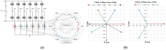
Figure 6.
Dual phase winding layout of the 7-pole–3-phase and 8-pole–6-phase configurations within a single motor (a) Mechanical winding layout diagram for the 7-pole–3-phase and 8-pole–6-phase configurations with a 6-phase inverter; (b) electrical winding layout diagram in the frequency domain for the 7-pole–3-phase and 8-pole–6-phase configurations.
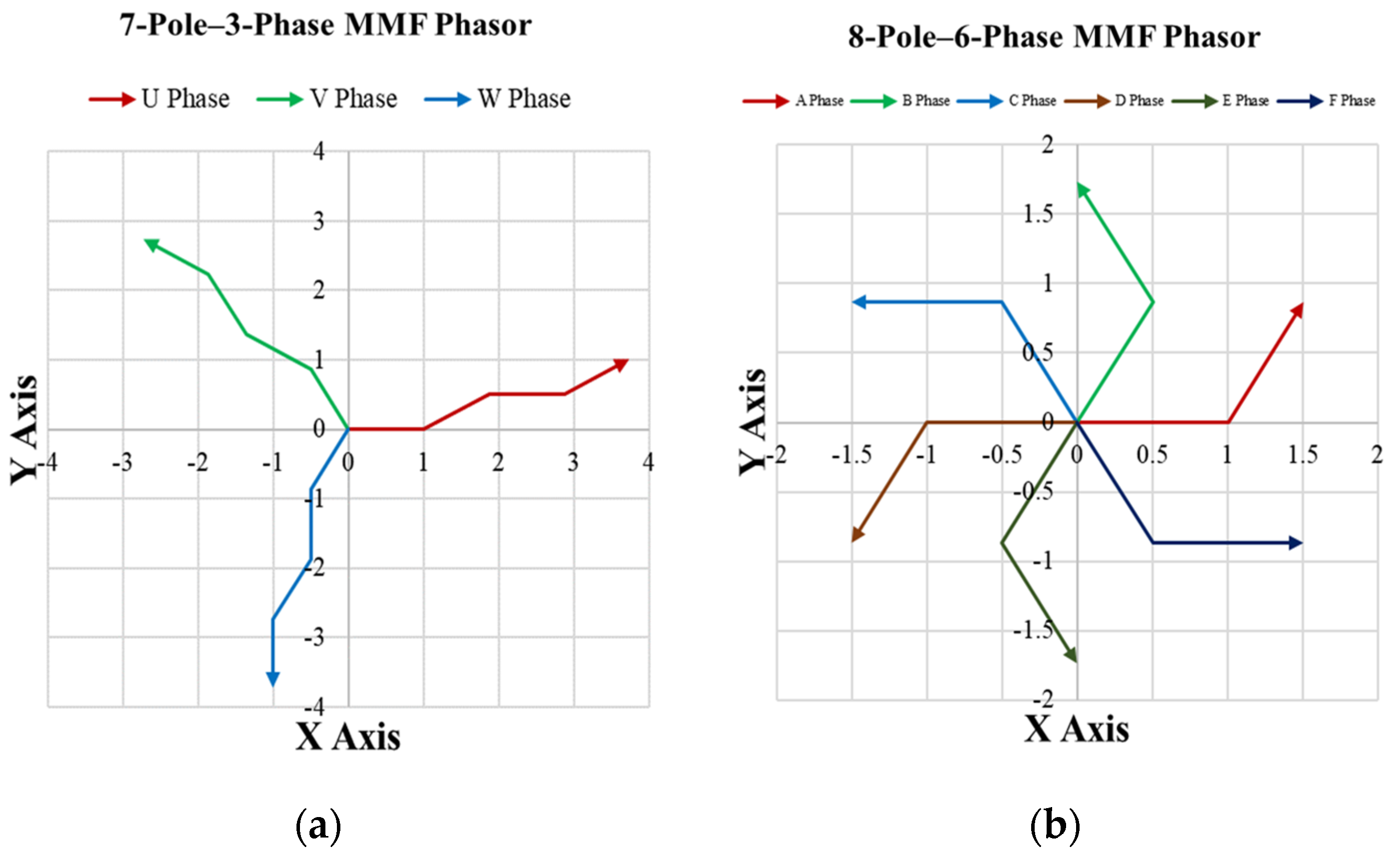
Figure 6a shows that the 3-phase is wound across two areas per phase, while the 6-phase exist in only one area. Figure 6b demonstrates that the electrical spacing between slots varies depending on the combination of poles and slots. After selecting the winding phasor optimized for the 3-phase with a high winding factor, Figure 6a can be completed by synchronizing the 6-phase phasor with the 3-phase phasor. To resolve the phase difference between the 3-phase current and 6-phase current when applying current through the same in/out, the inverter connects 3-phase in series and 6-phase in parallel. The winding method shown in Figure 6 can be verified for independent drive capability using MMF phasor and FEA data. Figure 7 shows each phasor normalized to a magnitude of one. There are two reasons for the differences between the two phasor sets. The first one is electrical angle difference. As shown in Figure 6, the 7-pole–3-phase and 8-pole–6-phase systems have different electrical angles. The 3-phase system is linked to 7- pole, while the 6-phase system is linked to 8-pole, resulting in different phasor angles. The 7-pole–3-phase system, with its smaller phasor angle, has a larger vector sum. The second one is different number of slots per phase. The vector sum magnitudes differ due to the different number of slots per phase. The vector sum of phases U, V, and W is larger because the 3-phase and 6-phase systems use the same stator. In the 6-phase system, phase U splits into phase A and phase D, phase V into phase B and phase E, and phase W into phase C and phase F. This division results in different vector magnitudes. Consequently, the overall vector sum is larger for the 7-pole–3-phase system. This characteristic is typical of the transition from a 3-phase to multiphase system. More detailed information on this topic is provided in Section 3.1.
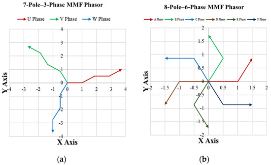
Figure 7.
MMF phasor diagram according to the number of poles and phases. (a) MMF phasor diagram for phases U, V, and W in the 7-pole–3-phase current frequency domain and (b) MMF phasor diagram for phases A, B, C, D, E, and F in the 8-pole–6-phase current frequency domain.
2.3.3. Analysis of Independent Operation in a DPM
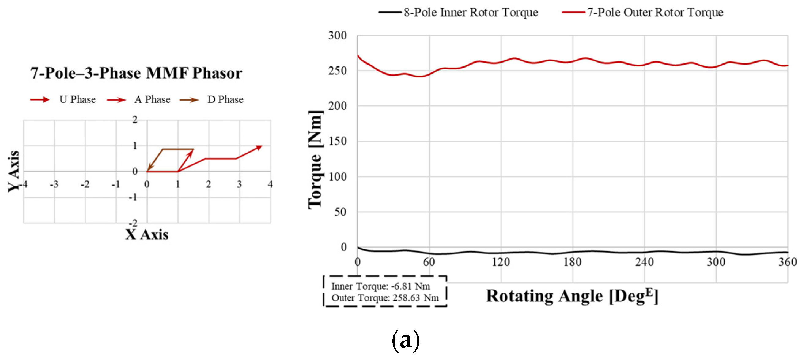
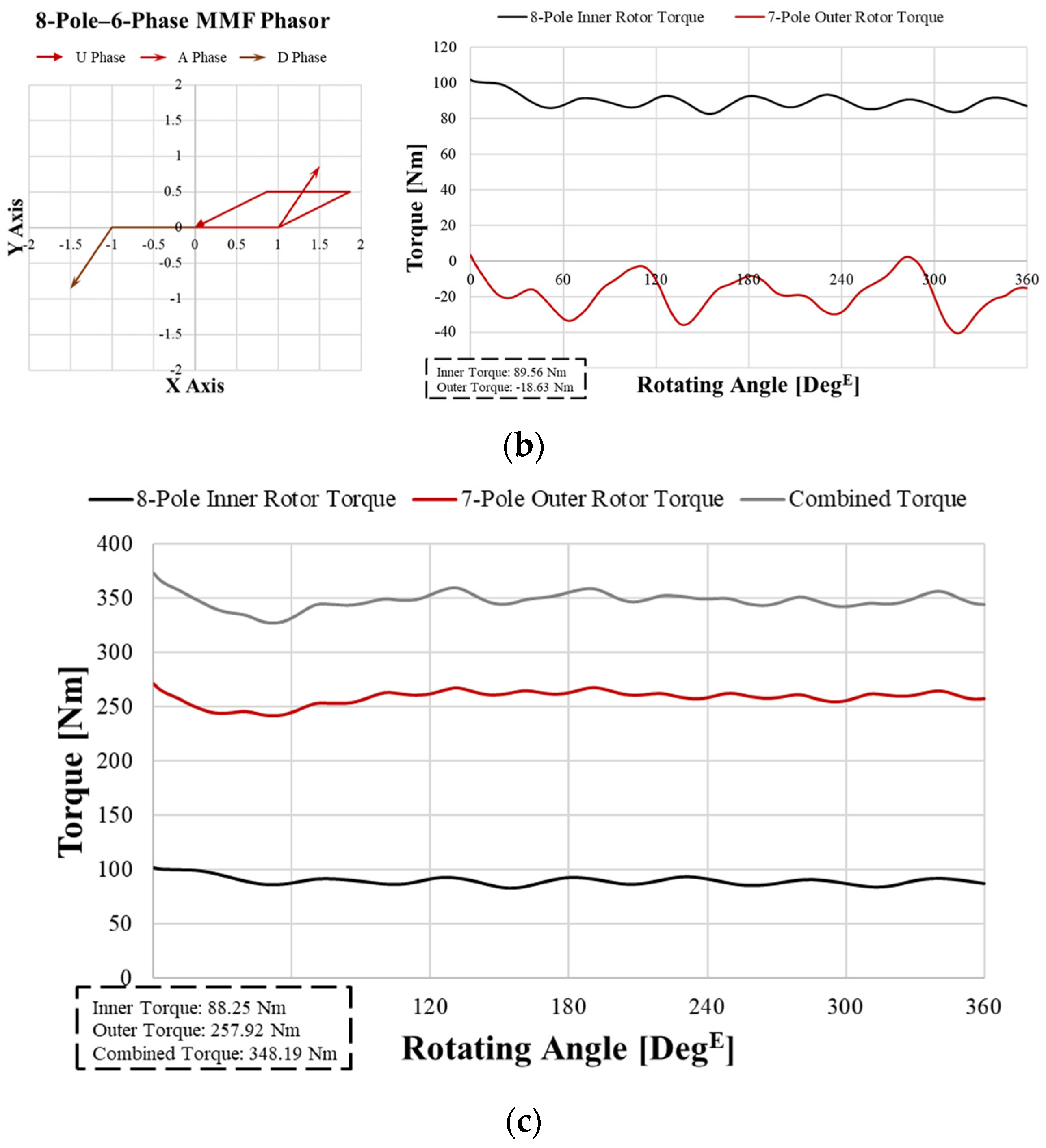
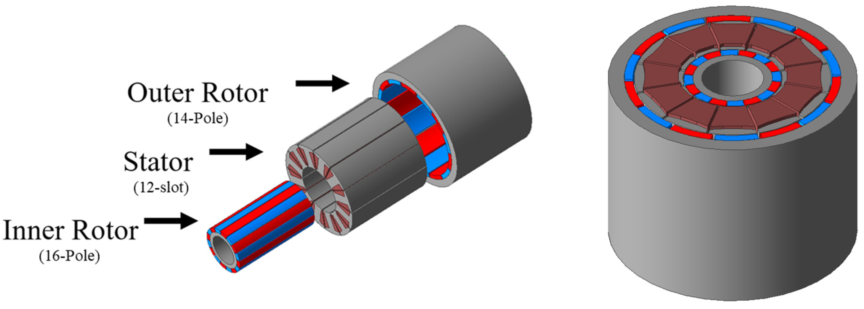
The 8-pole–6-phase configuration is represented in the MMF phasor of the 7-pole–3-phase current frequency domain, and the vectors cancel out, as shown in Figure 8a. Therefore, when a 212-Arms 3-phase current is applied, torque is generated only on the 7-pole outer rotor, as shown in Figure 8a. Conversely, when the 7-pole–3-phase configuration is represented in the MMF phasor of the 8-pole–6-phase current frequency domain, the vectors cancel out, as shown in Figure 8b. Thus, when a 212-Arms 6-phase current is applied, torque is generated only on the 8-pole inner rotor, as shown in Figure 8b. Although there is a slight error due to interference between the 8-pole and 7-pole, it can be confirmed that the average torque value is not generated, proving that the DPM achieves independent drive. Figure 8c shows that when 212 Arms are applied to both the 3-phase current and 6-phase current, torque is generated independently but simultaneously on the 8-pole inner rotor and 7-pole outer rotor, confirming that there is no issue with simultaneous drive. From now on, when both rotors are driven, the torque will be represented as combined torque, which is the sum of inner rotor torque and outer rotor torque. Using the 8:6:7 combination, the inner rotor is selected as 16-pole (6-phase motor), the stator as 12-slot, and the outer rotor as 14-pole (3-phase motor). The detailed 3D design and specifications of the DPM are shown in Figure 9 and Table 2.
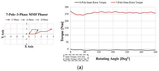
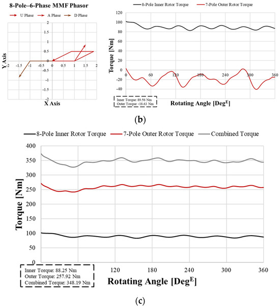
Figure 8.
Verification of independent operation through torque waveforms according to current injection: (a) 3-phase and 6-phase MMF in the 3-phase current frequency domain and FEA torque data for 3-phase current injection, (b) 3-phase and 6-phase MMF int he 6-phase current frequency domain and FEA torque data for 6-phase current injection, and (c) FEA torque data for the 3-phase and 6-phase combined current injection.

Figure 9.
3-dimensional design of the DPM.
Table 2.
DPM specifications.
3. Defining the Combined Current and Selecting the Best Ratio of Currents
3.1. Current Features in DPM Subsections
When transitioning from a 3-phase motor to a multiphase motor, the current has issues. Using the same motor design and Pin as a reference, when changing from a 3-phase motor to a 6-phase motor, phase U becomes phase A, and phase U* becomes phase D. To compare the results based on the same Pin, Equations (4)–(6) must be considered.
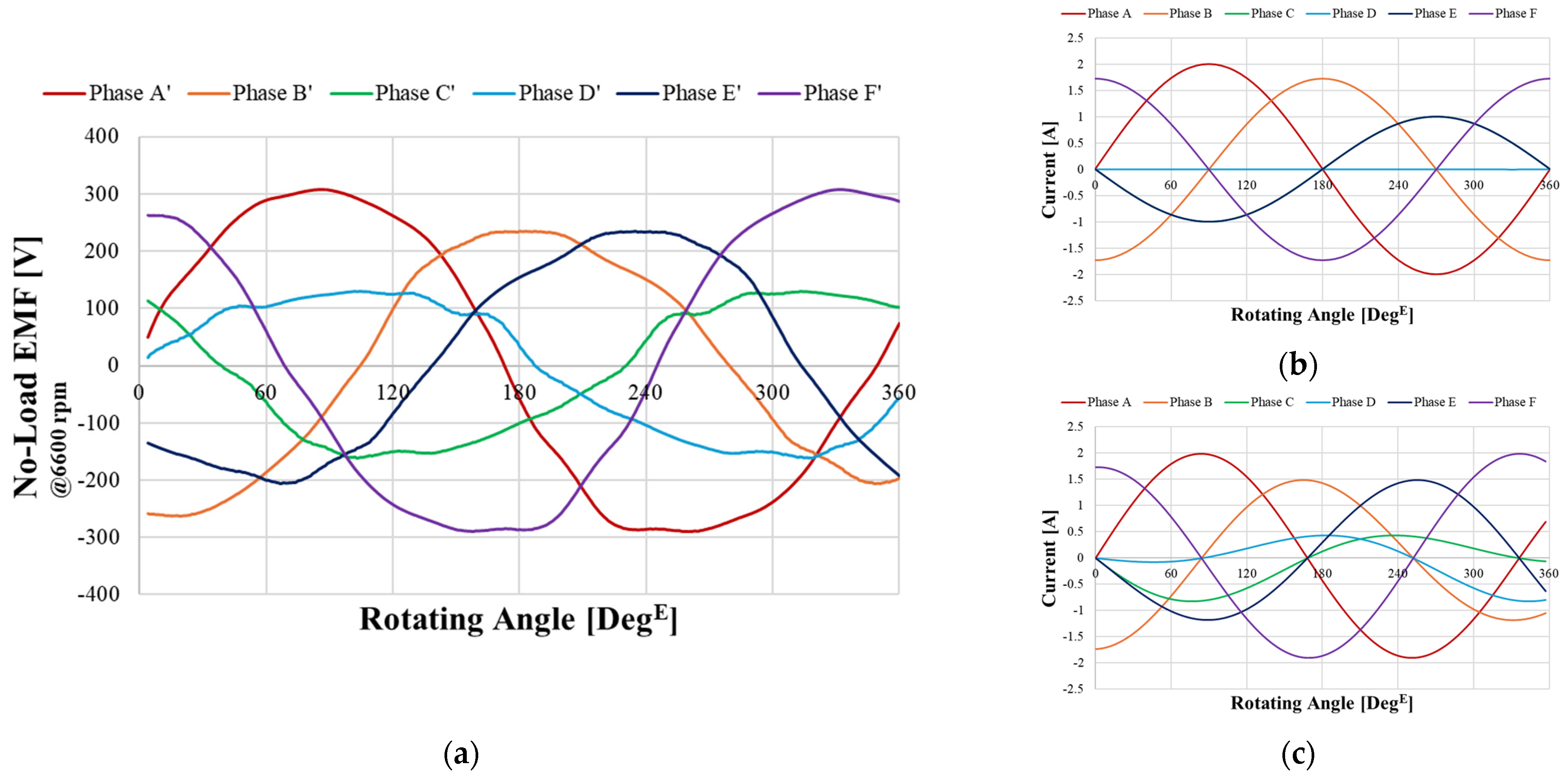
Case 1 is where the phase number of serial turns is the same. For this, NParallel_3Phase = 2NParallel_6Phase must be true. However, as Pin must remain constant, I3Phase= 2I6Phase. Case 2 is where the total number of serial turns is the same. For this, the phase number of serial turns for phase U is divided between phase A and phase D. As a result, V3Phase= 2V6Phase. Since Pin must remain constant, I3Phase= I6Phase. As a result, when transitioning from a 3-phase motor to a 6-phase motor, the current of Case 1 is I3Phase= 2I6Phase, while the current of Case 2 is I3Phase= I6Phase. This principle can be expanded to other multiphase systems, allowing for generalization through Equations (7)–(9). In Equations (7)–(9), N represents the number of phases in the motor, and XNPhase represents the value of X when there are N phases. For example, VNPhase signifies the value of V (voltage) when the motor has N phases. However, when the 3-phase current and 6-phase current are applied as a combined current to an independent drive motor, it differs from Equations (7)–(9). The first issue is related to the voltage. Figure 10a shows the no-load phase BEMF (Back Electromotive Force) of the DPM. The waveforms from phase A’ to phase F’ are not same and deviate significantly from a sinusoidal wave. This is because the inner rotor and outer rotor have different numbers of poles and are asymmetrical. So, the BEMF to be generated differently for each phase. Instead of using methods like Equations (7)–(9), we should choose an approach that inputs current like the waveform in Figure 10a. This is because matching the voltage and current waveforms results in high torque with less ripple. The second issue is the frequency difference due to the different numbers of poles. Figure 10b shows the combination of the 3-phase current and 6-phase current with the same period (frequency). When the periods are the same, phase D is canceled out, and phases C and E have no phase difference. This results in a meaningless current waveform. However, in a DPM where there is a frequency difference due to a difference in pole numbers, all phases have differences in magnitude and phase, as shown in Figure 10c. Sinusoidal waves have a constant magnitude and period. When synthesizing sinusoidal waves, both the magnitude and period must be considered. First of all, this study will consider the magnitude.
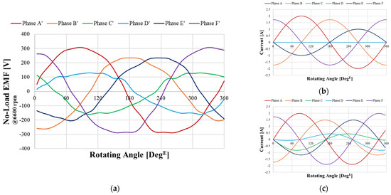
Figure 10.
Current waveform analysis according to frequency for the BEMF: (a) no-load phase BEMF of the DPM, (b) combined current (same frequency), and (c) combined current (not the same frequency).
3.2. Current Ratio
Waves have the characteristics of constructive interference and destructive interference. When waves are combined, wave distortion occurs because of constructive and destructive interference. Therefore, there are two things to check when creating a combined current. The first is the RMS (Root Mean Square) value. When selecting the current density of a motor, it is determined by Equation (10). When synthesizing a combined current from 212-Arms 3-phase current and 212-Arms 6-phase current, the result of the current RMS is 299.81 Arms. This means that the RMS value of complex currents changes. Irms, Irms1, and Irms2 are the RMS values of currents I, I1, and I2. Scoil represents the area of the coil. NParallel is the number of parallel circuits. ICrms is the RMS value of the combined current. Ratio refers to the ratio between Irms1 and Irms2, while Nratio is a constant used to determine the magnitude based on the ratio of Irms1 and Irms2 relative to the combined current.
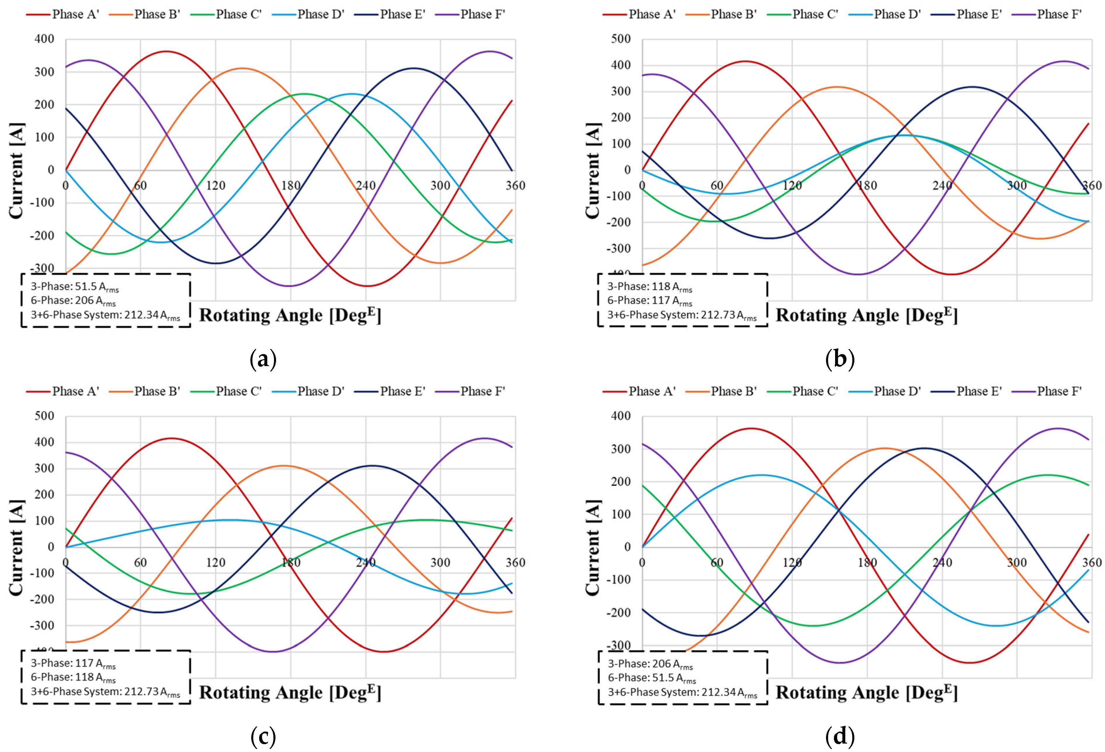
So, we need to define a new Irms required to select the current density. Since the actual current flowing through the coil is the combined current, we use the RMS of the combined current (Icrms) as the standard. Second, we need to check the ratio of currents. The current in a DPM is the combined current of 3-phase and 6-phase currents, and so we need to examine the current waveforms according to their ratios. The waveforms of currents A to F in the combined current change regularly depending on the ratio of 3-phase to 6-phase currents. As the proportion of the 3-phase current increases, the phases of phase A’ and phase D’, phase B’ and phase E’, phase C’ and phase F’ become more similar like a 3-phase current waveform. Conversely, as the proportion of the 6-phase current increases, the phase differences between phase A’ to phase F’ approach 60 degE. Through this ratio adjustment, we need to select a current waveform like that in Figure 10a. To find a current that satisfies these two conditions, we propose Equation (11), and Table 3 creates a compound current to reflect these results, as shown in Figure 11.
Table 3.
RMS conversion constant based on the ratio.
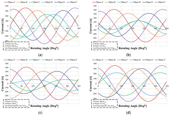
Figure 11.
Combined current ratios: (a) 2:8, (b) 4:6, (c) 6:4, and (d) 8:2.
3.3. Determining the Combined Current and Matching with BEMF
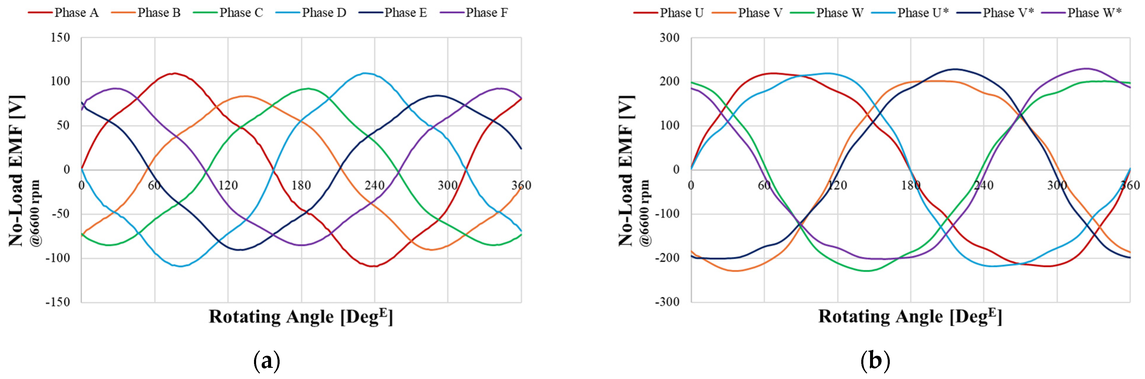
As described in Section 3.1, to apply a current with a ratio like the no-load BEMF, we independently drive the 8-pole inner rotor and 7-pole outer rotor, as shown in Figure 12. Figure 12 shows that depending on the pole and slot combination, when only the inner rotor is rotated, a BEMF corresponding to 6-phase is generated, and when only the outer rotor is rotated, a BEMF corresponding to 3-phase is produced. Figure 13a compares the waveforms of the 8-pole inner rotor phase A BEMF and the 7-pole outer rotor phase A BEMF. By analyzing the waveforms, we can see that the period corresponds to each linked pole. It is evident that the 8-pole system, with more poles, produces a shorter period.
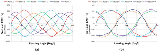
Figure 12.
Phase BEMF: (a) 8-pole inner rotor and (b) 7-pole outer rotor.
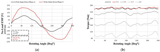
Figure 13.
Relationship between the BEMF ratio and input current. (a) Inner rotor and outer rotor BEMF comparison. (b) Torque comparison by current ratio.
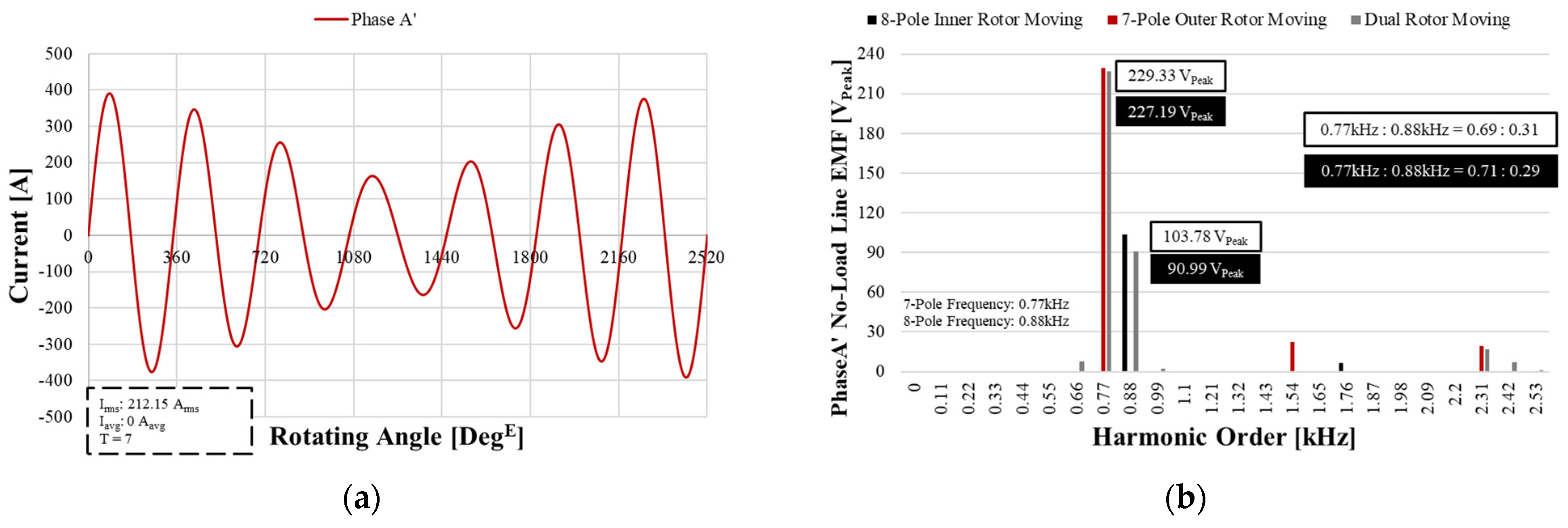
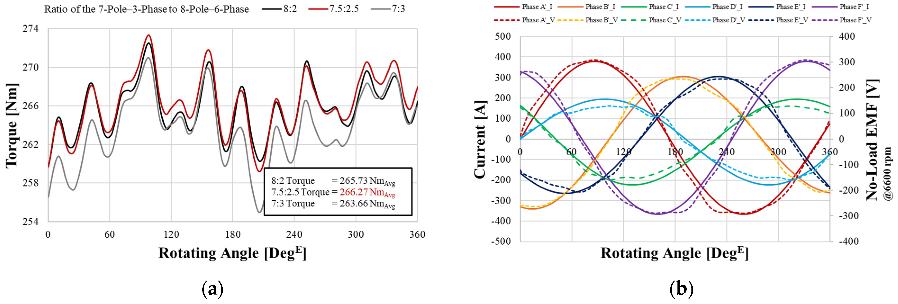
Regarding the waveform magnitude, the ratio of 7-pole–3-phase outer rotor to the 8-pole–6-phase inner rotor is 68.93:31.07, which is approximately 7:3. Therefore, the current is also set with a ratio of a 3-phase current to 6-phase current = 7:3. Figure 13b shows the result of applying the combined current to the DPM based on this current ratio, using 212 Arms as a reference. As analyzed in Figure 13a, we can confirm that applying the combined current with a 7:3 ratio produces the highest torque. However, Figure 11 shows that the phase A current does not become 0 A at 360 degE. The combined current, which is a synthesis of two waveforms with different periods, requires a new definition of one cycle. The period of the sinusoidal wave synthesis can be defined by the electrical frequencies of 8-pole and 7-pole, as shown in Equations (12) and (13). The reason for setting T1 as in Equation (12) is that when Poleouter > PoleInner, Touter < TInner. If we set TInner as T1, Touter would not complete one cycle. Since T = 1/f, TTotal is divided by the size of PoleInner, as shown in Equation (13). Figure 14 demonstrates that a complete cycle of current converging to zero is formed at TTotal = 7T1. This proves that the period of the DPM is 7T1, allowing for a more detailed analysis. At 6600 rpm, the frequency of 7-pole is 0.77 kHz, and the frequency of 8-pole is 0.88 kHz. When performing an FEA analysis of the DPM over 7T1 and applying FFT (fast Fourier transform), we can identify the frequency domains of the 7-pole and 8-pole systems. This means that even if the FEA results show an unbalanced waveform that is not sinusoidal, like in Figure 10a, we can still distinguish and analyze the 7-pole–3-phase outer rotor and 8-pole–6-phase inner rotor through FFT. Figure 14b shows the FFT of the phase A no-load line BEMF analyzed over 7T1. The FFT data for the no-load line BEMF in Figure 14b shows that the magnitudes and ratios of 0.77 kHz and 0.88 kHz obtained from individually driving the inner rotor and outer rotor are very similar to those obtained from driving the dual rotor. However, when driving the dual rotor, the proportion of 0.77 kHz is larger. Considering the armature reaction under load, we analyzed the results by increasing the current ratio of the 7-pole–3-phase system. As shown in Figure 15a, a better ratio than 7:3 was selected. This proves that analyzing the DPM over 7T1 yields more accurate results. In this paper, we selected I7Pole–3Phase:I8Pole–6Phase = 7.5:2.5. Figure 15b shows that the no-load phase EMF of the DPM and the 7.5:2.5 ratio combined current have similar waveforms. The reason for the specific ratio of phase voltage lies in the effective air gap surface and winding factor. Under the no-load condition, the magnitude of the phase BEMF is determined by the flux density of the effective air gap surface and the magnitude of the winding factor. The phase BEMF is determined by the interaction of these two factors. Therefore, as shown in Equation (14), the phase BEMF of the 8-pole inner rotor and 7-pole outer rotor can be predicted.
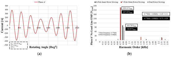
Figure 14.
Selection of the period for the combined current. (a) Phase A current (T = 7T1), (b) Phase A line BEMF FFT.
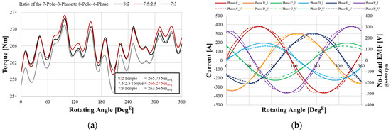
Figure 15.
Selection of the optimal current waveform based on output performance. (a) Torque compared to the current ratio, (b) comparison of the no-load phase BEMF and selected current.
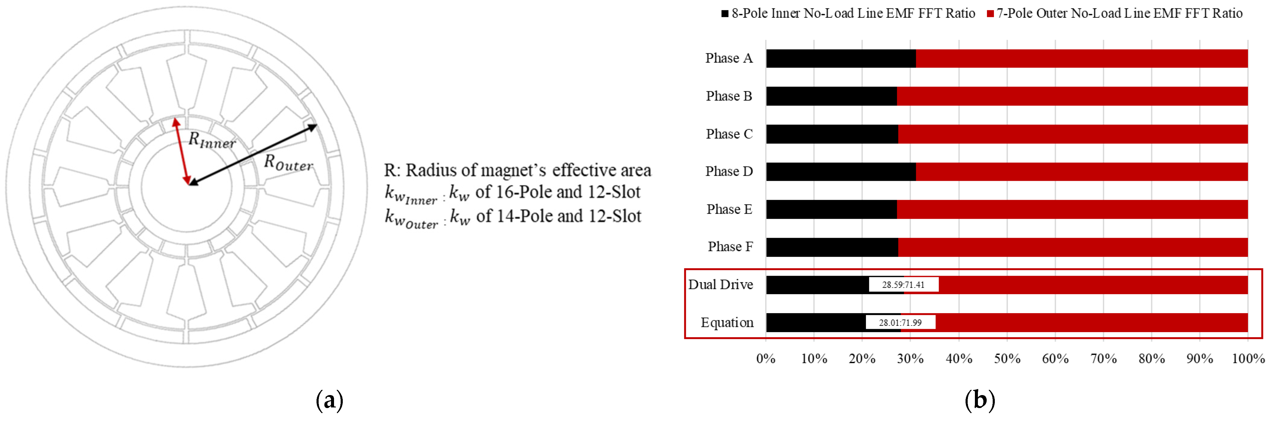
Since the calculation is based on the effective air gap surface, ROuter and RInner refer to the radii from the center of the motor to the middle point of the air gap for the outer/inner rotors, respectively. In terms of the motor output and magnetic field, the important factors are the grade of the magnet, the amount of magnet used, and the length of the effective air gap surface. However, in the case of the DPM, since the same magnet grade and thickness are used for both the inner rotor and outer rotor, only the effective air gap surface needs to be considered. The winding factor is explained in Section 2.3, and so it will be omitted here. Equation (14) presents the current ratio of each rotor based on these two factors. The geometry of Equation (14) is illustrated in Figure 16a. Figure 16b and Table 4 confirm the reliability of Equation (14). Simply comparing the phase BEMF of independently driven phases shows inconsistent ratios, leading to low reliability. However, when comparing the ratio obtained through FFT after simultaneous driving, which is relatively more reliable, with the equation, a very close match can be observed. This confirms the reliability of Equation (14). The DPM is designed to meet the voltage limit of 795 Vpeak at 6600 rpm at the rated point, considering the voltage margin. However, when the period is selected as 7T1, Figure 17 shows that the previously uneven voltage becomes uniform and lower. Therefore, Section 4 will focus on selecting a point considering the voltage margin and explain the driving method of the DPM in the high-speed region.
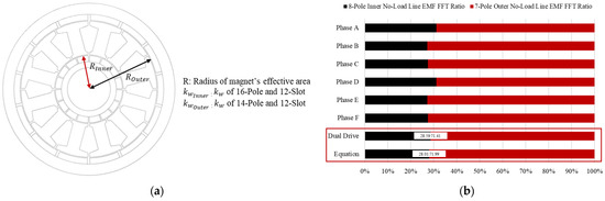
Figure 16.
Selection of the optimal current waveform based on output performance. (a) Illustration of the variables described in Equation (12) and (b) comparison of FEA data and Equation (12).
Table 4.
Comparison of FEA data and Equation (14).
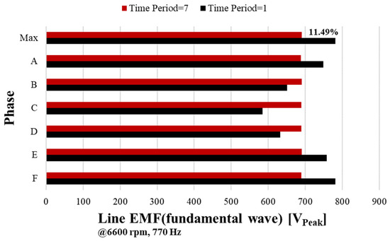
Figure 17.
Line voltage comparison of T1 and 7T1.
4. Drive and Control of the DPM
4.1. Rated Speed and High Speed of the DPM
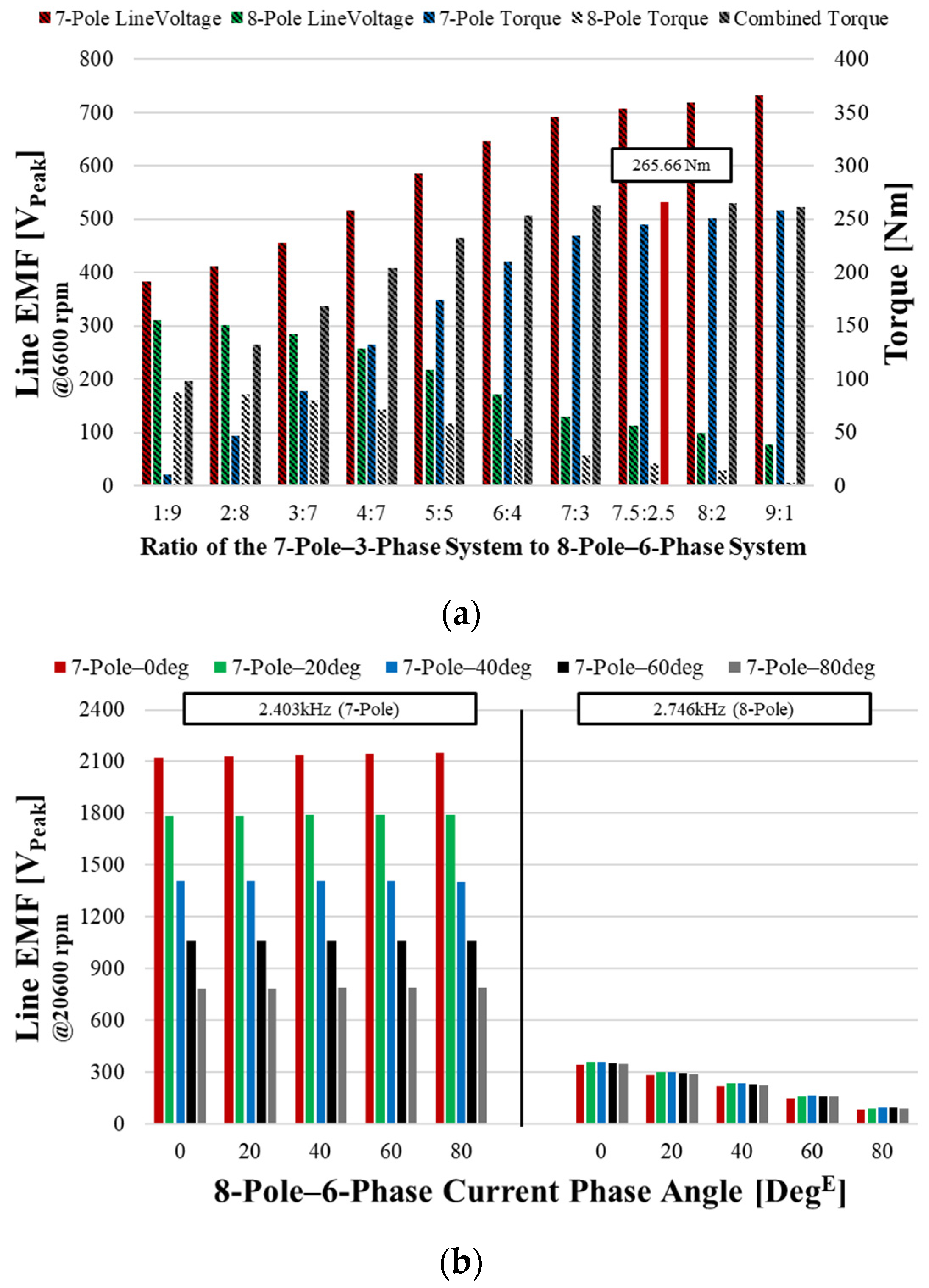
Now that the DPM design and combined current definition have been established, we need to find the rated speed point and high speed point instead of the previous 6600 rpm. The motor’s speed point is determined by the voltage limit. Voltage is determined by the magnetic flux and rotating speed. Therefore, an increase in rotating speed leads to an increase in voltage. Due to the characteristics of the DPM, its performance varies depending on the current ratio, and so it is necessary to examine the overall trends. To achieve speeds higher than the base speed, high-speed operation is achieved by reducing the magnetic flux of the voltage. To implement field weakening control, the phase angle of the current must be adjusted. In the case of the DPM, since combined currents with different frequencies are applied, it is necessary to synchronize the phase angle of the 3-phase current and 6-phase current. Using the frequency relationship, Equation (15) calculates degree of 8-pole–6-phase system correspondence to 1 degE of the 7-pole–3-phase system. In the case of a DPM, when Beta3Phase is 1 degE, Beta6Phase is 1.143 degE. Figure 18a shows the FEA results based on the current ratio with a 212-Arm combined current as the standard. In the case of the line EMF, it corresponds to the FFT values of 7-pole–0.77 kHz and 8-pole–0.88 kHz systems. Observing the changes in voltage according to the current ratio, we can confirm that as the current ratio increases, the line EMF also increases. As the ratio of the 7-pole–3-phase current increases, the magnitude of the 7-pole–line EMF increases, and as the ratio of the 8-pole–6-phase current increases, the magnitude of the 8-pole–line EMF increases. And, another characteristic is that the magnitude of the 7-pole–3-phase line EMF is larger. This is due to two reasons. First, the 7-pole–phase EMF is 7/3 times larger than the 8-pole–phase EMF according to Equation (14). Second, the phase EMF and line EMF magnitudes are the same at the 6-phase current. For the 3-phase current, the phase difference between adjacent phases is 120 degE, and so VLine = √3VPhase, but for the 6-phase current, the phase difference is 60 degE, and so VLine = VPhase. In other words, the 8-pole–6-phase line EMF is absolute smaller in terms of the MMF magnitude and scale. Figure 18b shows the results for the combinations of the 3-phase and 6-phase phase angles from 0 to 80 degE at a high speed of 20,600 rpm. The 7-pole–3-phase line EMF is only affected by the 3-phase phase angle, while the 8-pole–6-phase line EMF is only affected by the 6-phase phase angle.
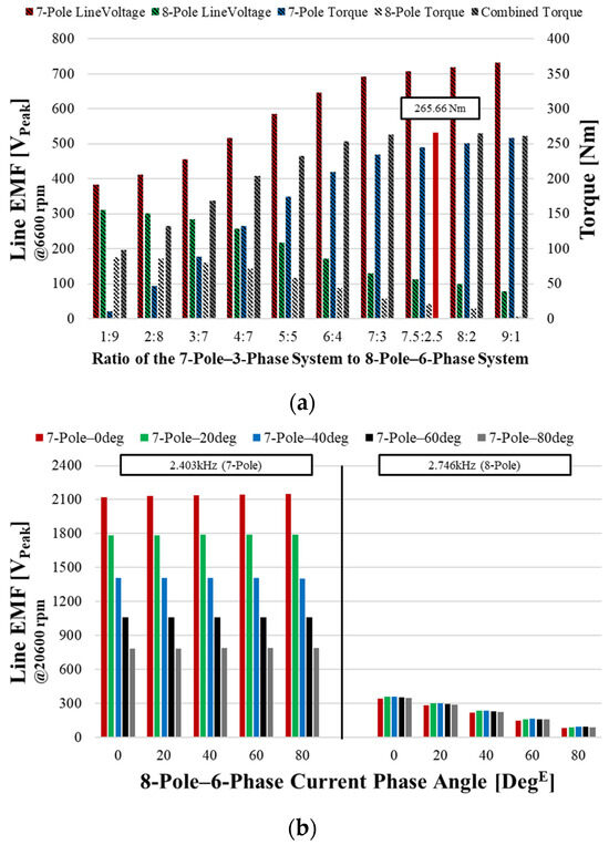
Figure 18.
Line voltage analysis at base and high speeds. (a) Voltage and torque according to the current ratio at 6600 rpm. (b) Voltage according to the phase angle at 20,600 rpm.
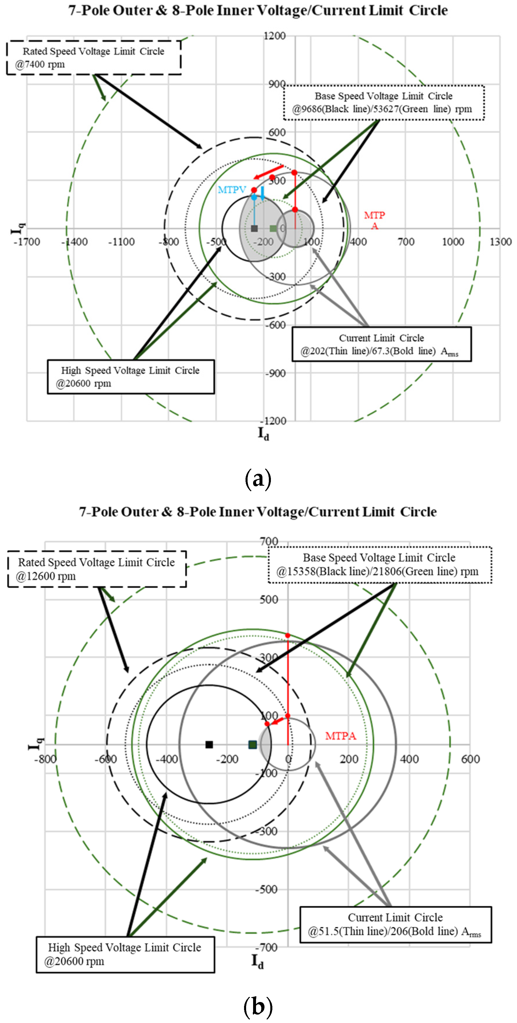
Based on the analysis in Figure 18, the operating characteristics of the DPM are represented through the voltage limit circle and current limit circle. Figure 19 shows cases where different current ratios are applied to the same DPM design. Figure 19a shows the voltage/current limit circle when applying the 7.5:2.5 ratio combined current selected in this paper, and Figure 19b shows the voltage/current limit circle when applying a 2:8 ratio combined current. In the same motor design, a 2:8 combined current was selected as a comparison group for comparing voltage/current limit circles because it can show extreme differences. As can be seen in Figure 18a, since the ratio of the current and the ratio of the voltage are linked, the 2:8 ratio was selected to see the case where the proportion of the 6-phase system is increased. The 1:9 ratio was excluded because operation was not possible at the high speed point of 20,600 rpm. The applied current, phase voltage from FEA results, and torque come out as complex waveforms at the DPM. It makes it difficult to understand the motor’s characteristics. However, it becomes possible to grasp the characteristics when dividing the 7-pole–3-phase region and the 8-pole–6-phase region. For the voltage, the data were interpreted by separating it like in Figure 14. In Figure 19, there are black and green lines, as well as solid and dashed lines.
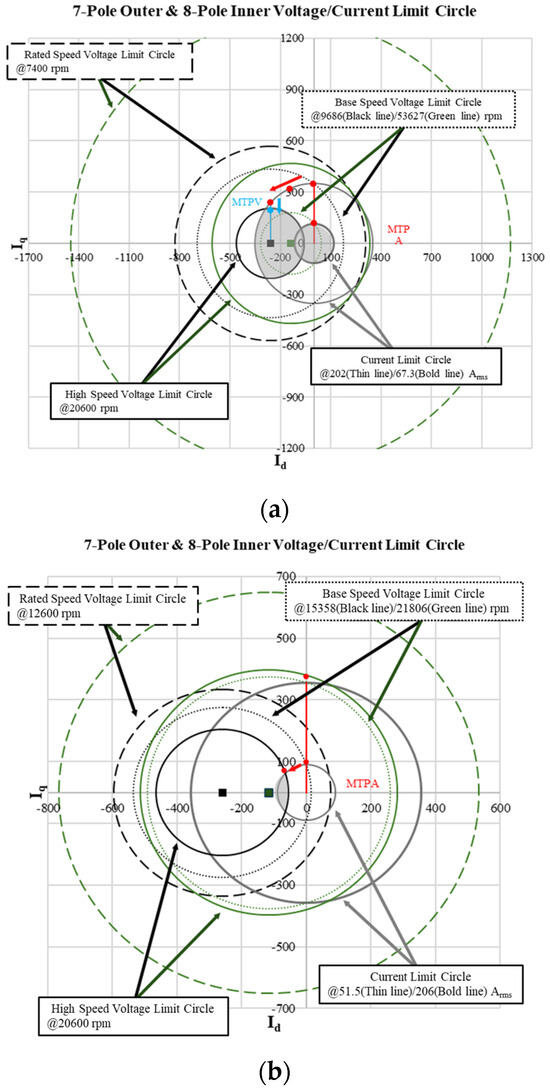
Figure 19.
Voltage/current limit circles: (a) 7.5:2.5 ratio and (b) 2:8 ratio.
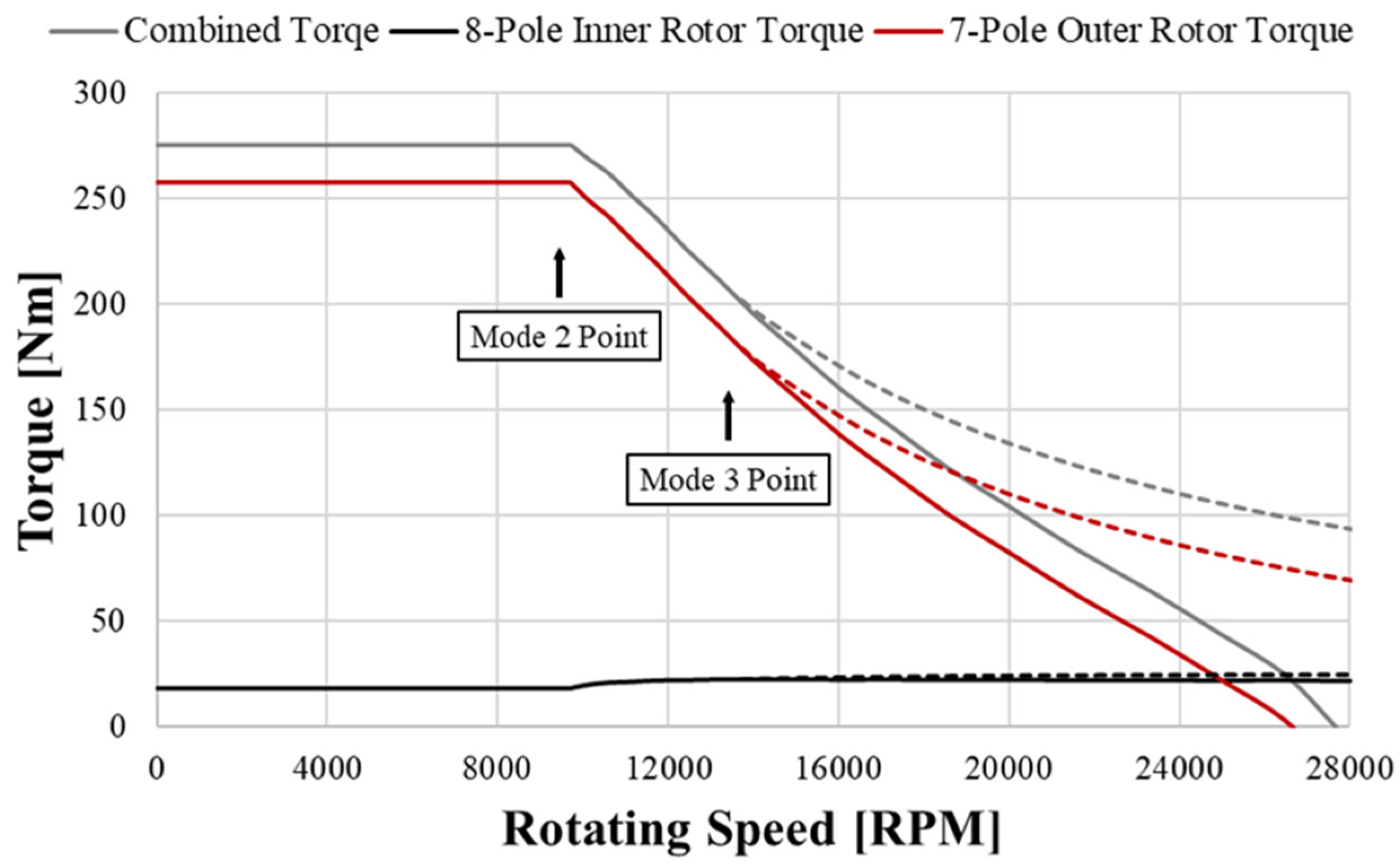
The black lines correspond to the 7-pole–3-phase system, and the green lines correspond to the 8-pole–6-phase system. Additionally, the solid lines represent the current limit circle, while the dashed lines represent the voltage limit circle. For the 8-pole–6-phase system, MTPA control is sufficient up to the high speed of 20,600 rpm at both the ratios of 2.5 and 8. In other words, the base speed when limiting to 970 Vpeak is larger than the high speed. However, the problem is the 7-pole–6-phase system. In Figure 19a, the origin of the 970 Vpeak voltage limit circle, point M, is inside the current limit circle. The rated speed has been adjusted to 7400 rpm with an 18% margin. Also, to reach 20,600 rpm, it reaches the MTPV control (Mode 3 control) point during field weakening control (Mode 2 control). Mode 3 control starts at the current phase angle of 38 degE. Mode 3 control can make high torque at high speeds and reduce copper loss due to current compared to Mode 2 control. Eventually, when applying a 7.5:2.5 current ratio, operation is possible in the shaded area of Figure 19a at 20,600 rpm. In Figure 19b, as the current magnitude of the 7-pole–3-phase system decreases from a ratio of 7.5 to 2, the voltage limit circle increases. But, the current limit circle decreases causing point M to move outside the current limit circle. The DPM exhibits different characteristics, depending on the current ratio, even when the same current RMS is applied. This is because the number of poles for the inner rotor and outer rotor are different and the ratio of 3-phase current to 6-phase current can be adjusted. Looking at the T-N curve in Figure 20, the inner rotor linked to 7-pole–3-phase can operate at 20,600 rpm in all cases. However, when using only Mode 2 control, operation ends near 27,000 rpm where the phase angle becomes 90 degE, as shown by the solid line. But, when using Mode 3 control, theoretically, it becomes possible to operate at even higher speeds, as indicated by the dashed line. The inner rotor linked to the 8-pole–6-phase system does not show significant changes, but there is a slight increase, as shown in Figure 20. As a result, operation becomes possible, like the combined torque.

Figure 20.
DPM (ratio of the 7-pole–3-phase current to the 8-pole–6-phase current = 7.5: 2.5) T-N curve.
4.2. Control Method for the DPM
A 3-phase motor is controlled by a 3-phase half-bridge inverter topology using two switches for each phase, in which case a maximum phase voltage of Vdc/√3 can be generated using six switching elements [16,17]. For a 3-phase and 6-phase combined drive motor, a 6-phase half-bridge inverter topology with two switches on each phase is used, consisting of 12 switching elements. When a 3-phase current is applied, torque is generated only in the 3-phase rotor, and when a 6-phase current is applied, torque is generated only in the 6-phase rotor.
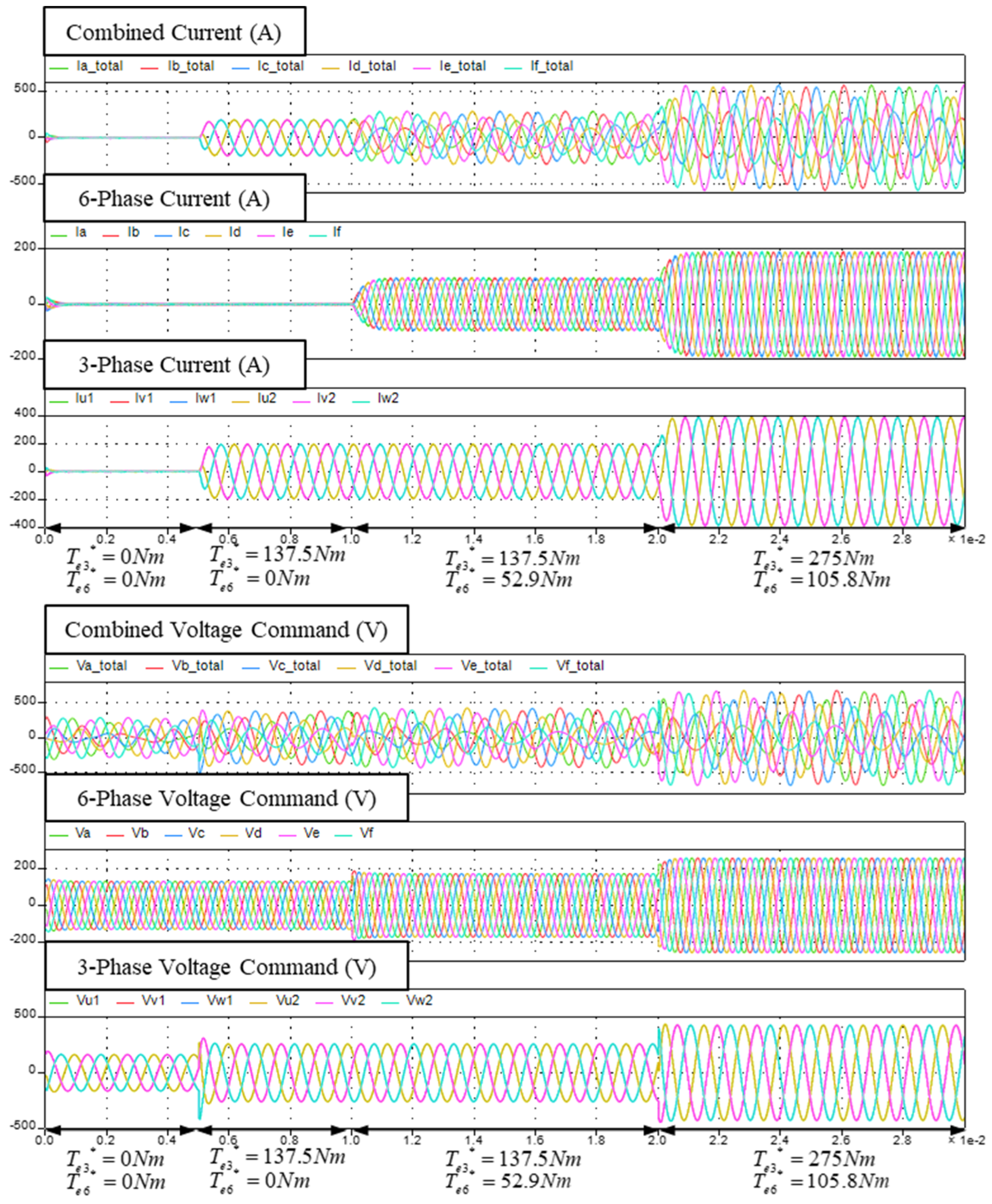
This provides an efficient 6-phase inverter topology that can control 3-phase and 6-phase motors with relatively few switching elements. A 3-phase rotor is modeled by (U1, U2), (V1, V2), and (W1, W2) parallel inductances, with an 120 degE phase difference between (U, V, W). On the other hand, a 6-phase rotor is modeled as an inductance with a 60 degE phase difference between (A, B, C, D, E, F). As shown in Equation (16), using two separate orthogonal coordinate systems (ds3-qs3 and ds6-qs6) to separate the space vectors, it is possible to independently control the 3-phase and 6-phase variables. And, it can implement a current controller without mutual interference between the two rotors. As shown in Figure 21, It can confirm that the voltage command is accurately generated according to the application of separated currents. This allows for the control of 3-phase and 6-phase rotor variables as DC values in the separated synchronous reference frames without mutual interference.
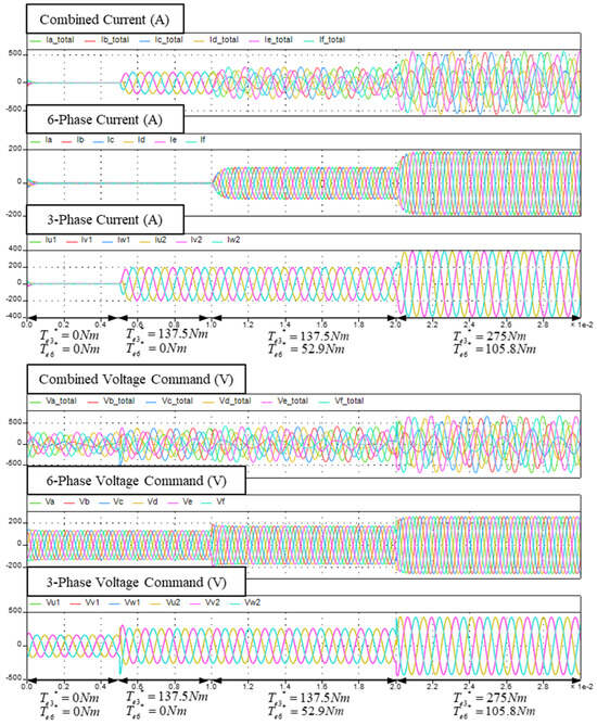
Figure 21.
DPM combined drive simulation for the simultaneous control of 3-phase and 6-phase rotors.
5. Conclusions
This paper presents the overall process for the design and operation of a DPM by demonstrating its operational characteristics according to speed and studying control methods, with the aim of proposing a design process for a DPM capable of independent operation as a method for achieving a high power density. To enable independent drive, a special combination of an inner rotor, outer rotor, and slots was selected, and a corresponding winding method was proposed. The winding method allows for an independent drive by applying two phases of current to a single stator. As the combined current using a 3-phase current and 6-phase current is used, a ratio of current that is like the voltage waveform is selected. Additionally, due to the different number of poles in the inner rotor and outer rotor resulting in different frequencies, a new period was selected. This period allows for the accurate selection of current ratios. And, it enables an independent analysis by decomposing the complex waveform FEA. The characteristics of the motor were studied by checking the voltage limit circles and the current limit circles according to the current ratios. The final model is a DPM with 8-pole–6-phase inner rotor and 7-pole–3-phase outer rotor configurations. The analysis of the different frequencies based on the different polarities of the inner rotor and outer rotor showed that the field weakening control for the high-speed region affects the phase angle control of the currents in each phase. The study found that the 8-pole–6-phase inner rotor configuration has a higher base speed than high speed. As a result, the field weakening control is only necessary for the 7-pole–3-phase outer rotor, which results in higher combined torque at high speed. This research verified the increase in the power density due to the high torque in the high-speed range of the DPM.
Author Contributions
Conceptualization, H.-S.H. and S.-W.S.; Methodology, H.-S.H., S.-W.S. and W.-H.K.; Validation, H.-S.H. and W.-H.K.; Formal analysis, H.-S.H., S.-W.S. and S.-B.J.; Investigation, H.-S.H., S.-W.S. and S.-H.L.; Resources, S.-H.L. and S.-B.J.; Data curation, S.-H.L. and S.-B.J.; Writing—original draft, H.-S.H. and S.-H.L.; Writing—review & editing, H.-S.H.; Supervision, S.-W.S. and W.-H.K.; Project administration, W.-H.K. All authors have read and agreed to the published version of the manuscript.
Funding
This work was supported by the Technology Innovation Program (No. 2410000834, Development of industrial DC servo motor technology of 750 W or less using anisotropic bonded magnets) funded by the Ministry of Trade Industry & Energy (MOTIE, Korea) and supported by the Korean Electric Power Corporation (Grant number: R22XO02-02).
Data Availability Statement
Data are contained within the article.
Conflicts of Interest
The authors declare no conflicts of interest.
References
- Du, G.; Hu, C.; Zhou, Q.; Gao, W.; Zhang, Q. Multi-Objective Optimization for Outer Rotor Low-Speed Permanent Magnet Motor. Appl. Sci. 2022, 12, 8113. [Google Scholar] [CrossRef]
- Sirimanna, S.; Balachandran, T.; Haran, K. A Review on Magnet Loss Analysis, Validation, Design Considerations, and Reduction Strategies in Permanent Magnet Synchronous Motors. Energies 2022, 15, 6116. [Google Scholar] [CrossRef]
- Shou, J.; Ma, J.; Zhang, Z.; Qiu, L.; Xu, B.; Luo, C.; Li, B.; Fang, Y. Vibration and Noise Optimization of Variable-Frequency-Driven SPMSM Used in Compressor Based on Electromagnetic Analysis and Modal Characteristics. Energies 2022, 15, 7474. [Google Scholar] [CrossRef]
- Hayashi, S.; Kubota, Y.; Soma, S.; Ohtani, M.; Igarashi, H. Topology Optimization of Permanent Magnet Synchronous Motor Considering the Control System. IEEE Trans. Magn. 2022, 58, 8205605. [Google Scholar]
- Liu, C.; Xu, Y.; Zou, J.; Yu, G.; Zhuo, L. Permanent magnet shape optimization method for PMSM air gap flux density harmonics reduction. CES Trans. Electr. Mach. Syst. 2021, 5, 284–290. [Google Scholar] [CrossRef]
- Cavagnino, A.; Lazzari, M.; Profumo, F.; Tenconi, A. A comparison between the axial flux and the radial flux structures for PM synchronous motors. IEEE Trans. Ind. Appl. 2002, 38, 1517–1524. [Google Scholar] [CrossRef]
- Wang, C.; Han, J.; Zhang, Z.; Hua, Y.; Gao, H. Design and Optimization Analysis of Coreless Stator Axial-Flux Permanent Magnet In-Wheel Motor for Unmanned Ground Vehicle. IEEE Trans. Transp. Electrif. 2022, 8, 1053–1062. [Google Scholar] [CrossRef]
- Zhang, Z.; Profumo, F.; Tenconi, A. Axial Flux Versus Radial Flux PM Motors; SPEEDAM: Capri, Italy, 1996; pp. A4-19–A4-25. [Google Scholar]
- Aydin, M.; Huang, S.; Lipo, T.A. Torque quality and comparison of internal and external rotor axial flux surface-magnet disc machines. IEEE Trans. Ind. Electron. 2006, 53, 822–830. [Google Scholar] [CrossRef]
- Haddad, R.Z. Iron Loss Analysis in Axial Flux Permanent Magnet Synchronous Motors with Soft Magnetic Composite Core Material. IEEE Trans. Energy Convers. 2022, 37, 295–303. [Google Scholar] [CrossRef]
- Syed, Q.A.S.; Solovieva, V.; Hahn, I. Magnetization Characteristics and Loss Measurements of the Axial Flux Permanent Magnet Motor’s Stator. In Proceedings of the 2019 IEEE International Electric Machines & Drives Conference (IEMDC), San Diego, CA, USA, 12–15 May 2019; pp. 1061–1066. [Google Scholar] [CrossRef]
- Demir, Y.; Aydin, M. A Novel Dual 3-Phase Permanent Magnet Synchronous Motor with Asymmetric Stator Winding. IEEE Trans. Magn. 2016, 52, 8105005. [Google Scholar] [CrossRef]
- Onsal, M.; Demir, Y.; Aydin, M. A New Nine-Phase Permanent Magnet Synchronous Motor with Consequent Pole Rotor for High-Power Traction Applications. IEEE Trans. Magn. 2017, 53, 8700606. [Google Scholar] [CrossRef]
- Li, K.; Wang, Y. Maximum Torque Per Ampere (MTPA) Control for IPMSM Drives Based on a Variable-Equivalent-Parameter MTPA Control Law. IEEE Trans. Power Electron. 2019, 34, 7092–7102. [Google Scholar] [CrossRef]
- Liu, T.-H.; Chen, Y.; Dai, B.-C. MTPA control for an IPMSM drive system using high frequency injection method. In Proceedings of the 2016 IEEE International Conference on Industrial Technology (ICIT), Taipei, Taiwan, 14–17 March 2016; pp. 181–186. [Google Scholar] [CrossRef]
- Bendjedia, M.; Tehrani, K.A.; Azzouz, Y. A new robust digital control of an induction motor supplied by a 3-level voltage inverter for electric vehicle applications. In Proceedings of the 2014 16th European Conference on Power Electronics and Applications, Lappeenranta, Finland, 26–28 August 2014; pp. 1–10. [Google Scholar] [CrossRef]
- Mondal, A.; Khan, J.; Prins, S.; Kumaravel, S. Control of Dual Motor Test Bench for Performance Testing of PMSM for Traction Application. In Proceedings of the 2023 IEEE Silchar Subsection Conference (SILCON), Silchar, India, 3–5 November 2023; pp. 1–6. [Google Scholar] [CrossRef]


Disclaimer/Publisher’s Note: The statements, opinions and data contained in all publications are solely those of the individual author(s) and contributor(s) and not of MDPI and/or the editor(s). MDPI and/or the editor(s) disclaim responsibility for any injury to people or property resulting from any ideas, methods, instructions or products referred to in the content. |
© 2025 by the authors. Licensee MDPI, Basel, Switzerland. This article is an open access article distributed under the terms and conditions of the Creative Commons Attribution (CC BY) license (https://creativecommons.org/licenses/by/4.0/).