Article

Comparison of Fixed Switching Frequency FCS-MPC Strategies Applied to a Multilevel Converter: A Case Study of a Hybrid Cascade Converter Based on 2L-VSI and H-Bridge Converters

by
Mauricio E. Arévalo
1,
Roberto O. Ramírez
2,*,
Carlos R. Baier
2,
Felipe A. Villarroel
3,
José R. Espinoza
4 and
Fernando P. Urra-González
2
1
Electrical Engineering Sciences Doctoral Program, Faculty of Engineering, University of Talca, Campus Curicó, Curicó 3344158, Chile
2
Department of Electrical Engineering, Faculty of Engineering, University of Talca, Campus Curicó, Curicó 3344158, Chile
3
Laboratorio de Aplicación en Sistemas Robóticos (LASiR), Department of Electrical Engineering, University of Talca, Curicó 3340000, Chile
4
Department of Electrical Engineering, Universidad de Concepción, Victor Lamas 1290, Concepción 4070386, Chile
*
Author to whom correspondence should be addressed.
Processes 2025, 13(4), 1214; https://doi.org/10.3390/pr13041214
Submission received: 12 March 2025 / Revised: 12 April 2025 / Accepted: 14 April 2025 / Published: 17 April 2025

Abstract

:
This paper evaluates the performance of strategies based on finite-control-set model predictive control (FCS-MPC) aimed at reducing or fixing the converter switching frequency or decreasing the spread of the harmonic spectrum in multilevel hybrid cascade converters (HCCs). These properties are desirable for medium- to high-voltage applications, where minimizing switching losses is crucial, as well as for applications employing passive filters, where resonance modes can be excited. The strategies evaluated are input restriction, notch filtering, period control, and PWM restriction. Key aspects considered in this work are (i) the evaluation of the steady-state and transient performance of FCS-MPC strategies proposed for two-level converters in a multilevel topology, and (ii) the evaluation of the computational cost associated with the implementation of these strategies on a multilevel converter with a high number of available inputs. As a typical application, the study is carried out employing a five-level HCC experimental prototype driving an induction motor through indirect vector control. To perform a fair comparison between the strategies, a control platform based on a cost-effective Zynq system on chip is proposed, which allows for achieving the hard timing constraints imposed by FCS-MPC strategies. The results show that the PWM restriction strategy achieves the best steady-state performance among the evaluated strategies, with an error 400 times smaller than that of the second-best strategy (input restriction), with an average switching frequency of 962.5 Hz, which differs from the desired average frequency by 3%, and a maximum difference in power distribution between modules of 0.8%. In addition, the system-on-chip hardware achieves a competitive execution time of 46 μs when the ARM Cortex solution is implemented and 20 μs when the ARM Cortex–FPGA solution is used instead, employing the 512 inputs available in the FCS-MPC algorithm. The studies, performed in steady-state and transient regimes, confirm (i) the feasibility of the evaluated algorithms in an HCC topology and (ii) the feasibility of the control platform for implementing high-computational-burden algorithms with a low sampling time.

1. Introduction

Multilevel power converters have made it possible to use low-voltage semiconductors in high-power applications. In comparison to traditional two-level topologies, these converters provide several advantages, including lower common-mode voltage, lower d v / d t stress, lower total harmonic distortion (THD), and a reduced switching frequency, among others. Nevertheless, these topologies come with their own challenges related to control, reliability, construction, scalability, and efficiency [1,2,3]. Among multilevel topologies, the hybrid cascade converter (HCC) based on isolated sources has the advantages of a lower component count [4,5], an extended negative sequence current compensation range when operating as a static compensator (STATCOM) [6], and high reconfigurability under fault conditions [6], in addition to other features.
Multiple control strategies use a modulation stage to generate gating signals for HCCs based on isolated power sources. However, to the best of the authors’ knowledge, the state of the art lacks sufficient proposals that employ finite-control-set model predictive control (FCS-MPC) as a viable alternative for current control. This could be due to the high number of available states in HCCs, along with the stringent power sharing requirements of the topology, both resulting in a high computational burden and a complex predictive algorithm [7,8]. This fact is discussed in [8], where a series of simplifications are required to successfully implement FCS-MPC in an HCC. However, these simplifications come at the cost of a suboptimal controller response with a high sampling time.
Strategies based on FCS-MPC have been favorably accepted as a viable alternative for controlling power converters due to their easy and intuitive digital implementation. This approach enables the control of nonlinear systems with multiple inputs and outputs while offering the possibility to include input constraints [9,10,11]. All of this has been made possible by the development of modern processors that enable the execution of high-computational-burden algorithms at high sampling frequencies [9].
In any power converter, the primary control objective is typically to minimize the tracking error; however, several secondary objectives can be incorporated, depending on the power converter topology, power quality constraints, or directly related to the use of an FCS-MPC strategy. Among these, common secondary control objectives include reducing the switching frequency [12,13], achieving a concentrated harmonic spectrum [14,15], ensuring even power sharing operation in multicell topologies [16,17], reducing the common-mode voltage, or minimizing output voltage jumps between non-adjacent levels [18], to name a few. Regarding HCCs operating with an FCS-MPC strategy, due to their similarities with the cascade H-bridge (CHB) converter, secondary objectives could focus on power distribution among cells and reducing or fixing the converter’s switching frequency to minimize switching losses and avoid possible resonant modes of the filter [19].
In the literature, several strategies have been proposed to improve the steady-state performance of conventional FCS-MPC. These strategies aim to reduce issues such as harmonic spectrum dispersion and high switching frequency. These proposals can be divided into two categories [20]: (i) utilizing the optimization stage of the predictive controller to calculate optimal duty cycles for a subsequent modulation stage [21,22,23,24], and (ii) incorporating a new control objective into the FCS-MPC cost function to reduce or mitigate switching transitions [13,14,25,26,27].
A different approach, though outside the scope of this work, involves predictive methods that inherently achieve a fixed switching frequency by including a modulation stage. Strategies that are part of this group, such as deadbeat predictive control (DB-MPC), continuous-control-set mpc (CCS-MPC), and modulated model predictive control (M2PC) have been successfully implemented despite the challenges they present. For instance, CCS-MPC involves a complex optimization problem formulation, particularly in multilevel inverter applications [28,29]. Meanwhile, DB-MPC schemes are highly sensitive to parameter variations, which can lead to oscillations and ringing [30,31]. In both cases, incorporating additional control objectives is not straightforward, requiring a reformulation of either the optimization problem or the modulation strategy [20,28,29,30,31]. Furthermore, the selection of the optimal state does not follow the standard formulation of a finite-state MPC controller [28,29,30,31]. On the other hand, M2PC follows a finite-state approach, where the duty cycles associated with standard space vector modulation are determined through cost function minimization [20,23,32]. In this case, this strategy poses challenges such as reduced dynamic response to disturbances and reference changes [20], and algorithm optimization to reduce the high computational burden associated with power converters that have a large number of available states [33,34].
To improve the switching characteristics of FCS-MPC schemes, Yaramasu et al. [13] propose including a control objective to penalize input changes between two consecutive sampling times, thereby reducing the average switching frequency in a two-level voltage source inverter (2L-VSI). Despite its simple implementation and successful results, the strategy retains the spread spectrum characteristic of the conventional FCS-MPC strategy. Cortes et al. [14] propose including a notch filter over the error signal in the cost function, allowing for the concentration of the current harmonic spectrum at the filter’s resonant frequency in a 2L-VSI. Unlike Yaramasu et al. [13], no weighting factor tuning is required, as the cost function remains unmodified. However, the strategy presents issues related to filter parameter design and does not ensure a switching pattern. Aguirre et al. [25] propose adding a control objective to fix the commutation period of each power converter semiconductor to achieve a fixed switching frequency in a 2L-VSI. The results show that the strategy is capable of achieving a concentrated and well-defined voltage harmonic spectrum; however, the results depend on the value of the weighting factor used. Moreover, the computational burden increases when the number of semiconductors increases, making the strategy infeasible for multilevel converters if high-performance hardware is not used. Finally, Ramirez et al. [15] propose including a control objective that penalizes the error between the current input and that proposed by a modulated output of a linear control scheme. This strategy allows the achievement of a reduced and fixed switching frequency with zero steady-state error and even power sharing among cells for a grid-connected single-phase CHB. Despite its promising results, the strategy has not been validated in three-phase converters or in other applications such as motor drives.
Previous work has focused on achieving a fixed or reduced switching frequency by modifying the cost function of the conventional FCS-MPC algorithm. This approach enables straightforward implementation in other power converters beyond the original proposal and facilitates the development of more advanced control strategies. For instance, Aguirre et al. [26,35] employed a notch filter and period control to improve switching frequency regulation in 2L-VSI and 5L-NPC topologies. Similarly, Baier et al. [36] implemented a similar concept to PWM-based restriction to reduce steady-state error through an integral term, while Aguirre et al. [37] applied period control to regulate the switching phase in interleaved DC-DC power converters. The state of the art shows that new strategies designed to enhance steady-state characteristics can be achieved by modifying or combining well-known approaches, such as input restriction, notch filtering, PWM restriction, or period control [13,14,15,25], among others. Thus, evaluating the behavior of these more straightforward strategies in a particular power converter is essential for developing more efficient control methods that improve switching frequency characteristics, reduce computational burden, and require less expensive hardware, while overcoming the control challenges inherent to the topology.
In this context, the HCC, which represents a promising topology for applications seeking to enhance power density, reduce the number of components [4,5], or that require improvements in fault tolerance characteristics [6], lacks sufficient studies that experimentally evaluate the performance of FCS-MPC strategies designed to fix or reduce the converter’s switching frequency.
In refs. [7,8], simulated and experimental results are presented to validate the application of predictive control in HCC. In these works, a series of admissible states are discarded prior to the optimization stage of the predictive algorithm to reduce the computational burden and make the implementation feasible. However, the results reveal typical predictive control issues related to steady-state performance, as it is not possible to apply the previously described strategies due to the insufficient number of available states in the optimization stage. The aforementioned issues can be mitigated using well-known and powerful hardware platforms such as OPAL-RT [38], dSPACE [39], or RTBox [40], which are capable of running algorithms with high computational burdens, allowing the evaluation of all available states of the power converter. However, these solutions are typically feasible only in laboratory environments and lack practicality for real-world implementations. In such cases, embedded solutions based on field-programmable gate arrays (FPGAs) or digital signal processors (DSPs) are the viable options. Nevertheless, implementing algorithms on FPGAs requires considerable development time, while relying on a specific DSP imposes hardware constraints that limit the possibility of future algorithm modifications.
For these reasons, this work proposes evaluating the performance of FCS-MPC strategies designed to reduce or fix the switching frequency in a 5-level HCC, based on isolated voltage sources, driving a three-phase induction motor. Unlike previous works [7,8], the comparison is conducted using the same topology and operating conditions, assessing performance in terms of harmonic spectrum, steady-state error, computational burden, power sharing among cells, and dynamic behavior under step reference changes. The strategies evaluated include input restriction [13], notch filtering [14], period control [25], and PWM restriction [15]. These strategies were selected for their well-documented implementation and successful results, although their application to the selected topology has not been reported in the literature. To address the computational burden associated with the high number of available states in the five-level HCC converter, the algorithms are implemented on a Zynq-7000 system-on-chip (SoC) [41,42], a cost-effective midpoint hardware solution between DSPs and FPGAs. As will be shown herein, the Zynq hardware allows for the evaluation of the 512 states of the converter in 20.6 μs, well within the sampling periods of typical FCS-MPC implementations. The key contribution of this paper lies in presenting and discussing the experimental behavior of FCS-MPC strategies with improved steady-state performance, along with their implementation challenges, when applied to an HCC under various operating conditions, thus providing a foundation for further research on the application of FCS-MPC strategies for this converter. The choice of the motor drive application as a case study is based on the high demand for motor drives, mainly driven by electro-mobility products, which require high standards of efficiency, power density, and reliability [43,44].
This paper is organized as follows: Section 2 describes the system proposed to compare the performance of the FCS-MPC strategies, which consists of a five-level HCC feeding an induction machine. Section 3 introduces the conventional FCS-MPC algorithm, and is followed by Section 4, which explains the predictive strategies with reduced or fixed switching frequency that are evaluated in this work. Section 5 applies the strategies to the experimental setup, comparing their performance in steady-state and transient regimes. Finally, the main conclusions of this work are presented in Section 6.

2. System Description

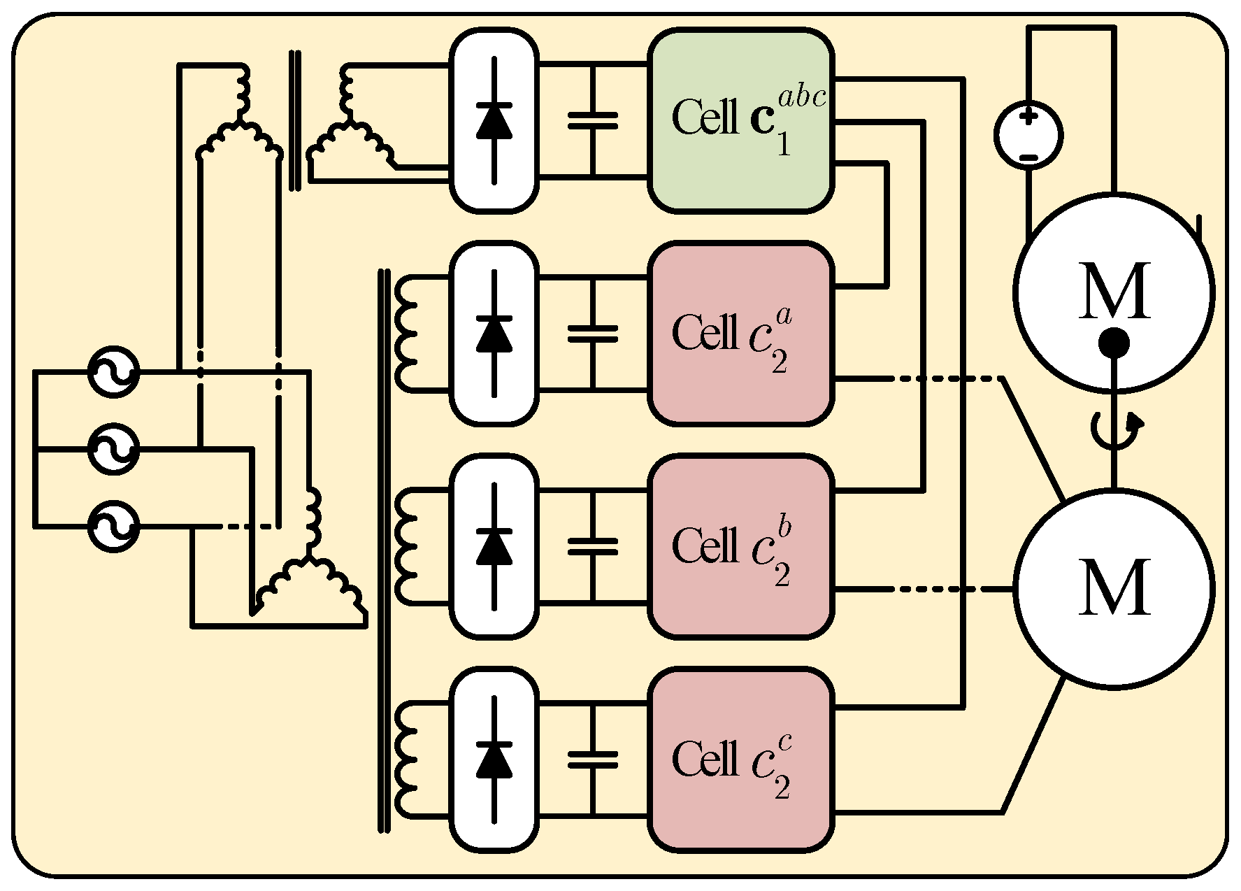
Figure 1 shows the system under study, composed of a 5-level HCC feeding a three-phase induction motor controlled by the well-known field-oriented control (FOC) method. The system employs a cascade control scheme, with a proportional–integral (PI) controller regulating the motor speed in the outer loop [24] and an FCS-MPC strategy controlling the phase currents in the inner loop. The performance of the current loop, a key aspect of the overall control system, is evaluated for each FCS-MPC strategy intended to fix or reduce the converter’s switching frequency, as detailed in Section 4.
Each component of the system is detailed below. The mathematical model of the 5-level HCC, FOC equations, and the conventional FCS-MPC algorithm are described to clearly define the prediction model and the system’s inputs and outputs. These equations provide a comprehensive understanding of the modifications introduced by the evaluated strategies into the conventional FCS-MPC scheme to achieve the desired control objectives and demonstrate how their performance is affected by the 5-level HCC.

2.1. Hybrid Cascade Inverter

The hybrid cascaded converter is a multilevel power topology built-up by connecting each phase of a 2-level voltage source inverter (2L-VSI) to an arrangement of series-connected H-bridge inverters. Compared to a traditional cascaded H-bridge (CHB) converter with the same number of cells, the HCC achieves an additional voltage level with fewer semiconductors and isolated voltage sources, resulting in a less bulky and more compact topology [4].
Figure 1 shows a 5-level HCC composed of a 2L-VSI and one cell per phase. For this converter, the load output voltage vector v f a b c = [ v f a v f b v f c ] T (see Figure 1) can be expressed as
v f a b c ( t ) = v v a b c ( t ) + v m a b c ( t ) v a b c 1 3 v o N ( t ) ,
where v a b c represents the phase voltage vector of HCC, composed of the 2L-VSI output voltage vector v v a b c and the vector associated with the cell arrangement voltage v m a b c , v o N (see Figure 1), the common mode voltage, and 1 3 is the 3-dimensional column vector of ones 1 3 = [ 1 1 1 ] T .
For control purposes, specifically for FCS-MPC strategies, it is useful to express the load voltage vector (1) as a function of the discrete gating signals of the power converter [9]. This can be achieved by initially analyzing the output voltage of the 2L-VSI and the H-bridge arrangement as functions of their respective gating signals, and then calculating the resulting load voltage vector according to (1).
The 2L-VSI voltage vector can be written as a function of its associated gating signals, as follows:
v v a b c ( t ) = v d c v ( t ) 2 ( 2 s 1 a b c ( t ) 1 3 ) ,
where v d c v stands for the dc-link voltage and s 1 a b c = [ s 1 a s 1 b s 1 c ] T for the switching function of the 2L-VSI. For the series-arrangement of H-bridges, the voltage vector as a function of their gating signals is given by
v m a b c ( t ) = v m a ( t ) v m b ( t ) v m c ( t ) = v d c m ( t ) s 2 a ( t ) s 3 a ( t ) s 2 b ( t ) s 3 b ( t ) s 2 c ( t ) s 3 c ( t ) = v d c m ( t ) ( s 2 a b c ( t ) s 3 a b c ( t ) ) ,
where the pair { s 2 x , s 3 x } for x { a , b , c } represents the gating signal of the H-bridges connected to the corresponding phase x, as shown in Figure 1 and v d c m is the DC-link voltage associated with each cell, for which, for analysis purposes, the same value is imposed across all cells. Finally, from the 2L-VSI voltage vector (2) and H-bridge voltage vector (3), the common-mode voltage v o N can be calculated as
v o N ( t ) = v a ( t ) + v b ( t ) + v c ( t ) 3 = i = a , b , c v d c v ( t ) 2 ( 2 s 1 i ( t ) 1 ) + v d c m ( t ) ( s 2 i ( t ) s 3 i ( t ) ) 3 ,
which allows the load voltage vector to be rewritten as a function of the gate signals as
v f a b c ( t ) = v d c v ( t ) 2 ( 2 s 1 a b c ( t ) 1 3 ) + v d c m ( t ) ( s 2 a b c ( t ) s 3 a b c ( t ) ) 1 3 v o N ( t ) .
From Equation (5), if the DC-link voltage of the 2L-VSI has the same value as the DC-link voltage of the H-bridge cells ( v d c m = v d c v ), the HCC operates similarly to the asymmetric cascaded H-bridge (CHB) inverter [4]. To avoid this operating condition, in this work the DC-link voltage of the 2L-VSI is defined as v d c v = 2 v d c m .

2.2. Motor Model Under the Field-Oriented Control Strategy

The 5L-HCC described above and shown in Figure 1 drives an asynchronous machine with the well-known field-oriented control strategy [45]. The stator equations in the dq reference frame, oriented with the rotor flux, can be written as
d i s d q ( t ) d t = R s i s d q ( t ) σ L s + 0 ω e ( t ) ω e ( t ) 0 i s d q ( t ) + 0 ω e ( t ) L o L r ψ r d ( t ) σ L s v s d q σ L s ,
where v s d q , i s d q , and ψ r d q are the vectors expressed in the dq reference frame associated with the motor voltage, current, and flux, respectively, and ω e represents the electrical stator frequency, which is related to the rotor frequency by the number of pole pairs: ω e = p · ω r [45] (see Figure 1). The parameters are defined in Table 1. The stator equations presented in (6) are utilized in the following subsection to derive the discrete prediction model required for the FCS-MPC strategy used to control the stator currents and regulate the motor speed.
With the described FOC strategy, it is possible to control the magnetic torque and magnetic field separately, provided that the Park transform is properly oriented with the machine [24]. In this way, the flux depends on the direct component ( i d ), while the torque depends on the quadrature component ( i q ).

3. Finite-Control-Set Model Predictive Control

FCS-MPC algorithms use the discrete system model to estimate its future behavior for a defined prediction horizon. At each sampling time, the controller selects and applies the input that minimizes a cost function composed for the desired control objectives. In particular, power converters have a finite and discrete number of inputs that allow the theoretical evaluation of all available inputs to the system [9]. The prediction model for the next sampling time k + 1 can be expressed as a function of the system state vector x ( k ) and the system input vector u ( k ) at the current sampling time k as
x ( k + 1 ) = f m ( x ( k ) , u ( k ) ) ,
with f m ( · ) representing the prediction model defined by the system. The prediction model (7) is evaluated at each sampling time for all valid input values for the system. Then, the optimal input u o p t is calculated according to
u o p t = min j = 1 , . . . , N g ( u ( j ) ) ,
where N corresponds to the number of available discrete inputs and g ( · ) the desired cost function. For instance, if the control objective is reducing the tracking error for a reference vector x r e f ( k + 1 ) , a quadratic cost function can be defined as
g = ( x r e f ( k + 1 ) x ( k + 1 ) ) T ( x r e f ( k + 1 ) x ( k + 1 ) ) .
In this case, u o p t is the input that minimizes the tracking error. Figure 2 presents the conventional FCS-MPC flowchart, where computational delay compensation has been included, as described in [46]. The flowchart includes all the previously described steps, which are organized into the following stages: (i) measurement, (ii) optimal state application, (iii) delay compensation, and (iv) optimization.
Considering the system under study, the predictive model for stator currents i s d q ( k + 1 ) , required for stator current control, is obtained from (6) using the forward Euler method [9], resulting in
i s d q ( k + 1 ) = A d i s d q ( k ) + B d v s d q ( k ) .
where
A d = 1 + T s R s σ L s 1 + T s ω e ( k ) + R s σ L s 1 + T s ω e ( k ) R s σ L s ω e ( k ) + L o 2 σ L s L r + 1 1 + T s R s σ L s , B d = T s σ L s
This predictive equation is evaluated for the 512 available inputs (switching states) of 5L-HCC, and the optimal state is the input that minimizes the following cost function:
g = ( i r e f d q ( k + 1 ) i s d q ( k + 1 ) ) T ( i r e f d q ( k + 1 ) i s d q ( k + 1 ) ) .
As explained in the following section, to achieve a fixed or reduced switching frequency, each FCS-MPC strategy proposed in the literature modifies at least one stage of the predictive algorithm flowchart. However, the tracking objective (12) remains common to all of them.

4. Proposals Under Evaluation

This section presents four alternatives, already discussed in the literature, which aim to fix or reduce the switching frequency in FCS-MPC. These strategies are implemented in an HCC for performance comparison in the next section. Although several works have validated these strategies in the literature for specific power converters, no one has yet implemented them in a multilevel converter like the HCC as far as the authors are aware. The strategies have the particularity that they do not include modulation stages, and the fixed switching frequency objective is achieved through either (i) a new control objective in the cost function or (ii) reference modification.

4.1. Input Restriction

In Yaramasu et al. [13], the authors propose reducing the switching frequency by constraining the system input change between adjacent sampling times. In this manner, the system is able to maintain the same state for multiple sampling times, thereby reducing the number of transitions. The following cost function is implemented to achieve this operation:
g = λ ( s ( j ) s o p t ) T ( s ( j ) s o p t ) ,
where s is the switching vector associated with each power converter state, s o p t the optimal vector applied in the previous sampling time, and λ the weighting factor associated with this control objective.

4.2. Notch Filter

Cortés et al. propose concentrating on the harmonic spectrum by modifying the tracking error expression instead of the cost function [14]. This strategy is implemented by applying a notch filter to the tracking error:
i e ( k + 2 ) = F ( z ) ( i r e f ( k + 2 ) i s ( j ) ) ,
where i r e f ( k + 2 ) , i s ( j ) , and i e ( k + 2 ) represent the current reference, the estimated current for each state, and the current tracking error after the notch filter application, respectively. The notch filter F ( z ) corresponds to
F ( z ) = z 0 + b 1 z 1 . . . b n z n a 0 z 0 + a 1 z 1 . . . a n z n ,
with n the filter order. Thus, the cost function can be defined as
g = i e ( k + 1 ) T i e ( k + 1 ) .
It is important to note that the frequency response of the notch filter must be designed to generate resonance at the frequency at which the concentration of the harmonic spectrum is to be imposed. Furthermore, the bandwidth determines how restrictive the filter is: a wide bandwidth improves spectrum concentration but increases the steady-state error, while a narrow bandwidth reduces the steady-state error but fails to effectively concentrate the harmonic spectrum.

4.3. Period Control

Aguirre et al. [25] propose a new control objective that aims to fix the time between two falling edges T d and two rising edges T u of the converter gating signals, which allows their period to be fixed. The objective period vector T r has the same dimension as the converter states, and its components are equal to the desired commutation period T r . Therefore, the control objective is defined as follows:
g = λ ( ( T u T r ) T ( T u T r ) + ( T d T r ) T ( T d T r ) ) ,
where T u and T d are vectors that contain the elapsed time between two consecutive falling edges and two consecutive rising edges for each semiconductor, respectively. The values T u and T d are obtained by expressions that detect the rising and falling flanks. In addition, expressions are defined that allow these to be predicted to find, through prediction, the state that generates the lowest current tracking error and achieves a fixed switching period.
This algorithm controls the period of each switch, so the number of comparisons and calculations required grows according to the number of switches in the topology. Hence, as demonstrated in Section 5.4, its application is difficult in multilevel topologies.

4.4. PWM Restriction

Ramirez et al. [15] propose the inclusion of a control objective that seeks to impose a PWM pattern on the converter output voltage during steady-state operation. The switching reference vector s p w m used to impose this pattern corresponds to the PWM signal achieved from a classic linear modulated control scheme. A proportional–resonant (PR) regulator provides the modulation signal which is modulated through SPWM or SVM [47,48], resulting in the gating signals reference, which achieves zero error in steady-state and a concentrated harmonic spectrum. The PWM restriction control objective is defined as follows:
g = λ ( ( s p w m ( k ) s ( j ) ) T ( s p w m ( k ) s ( j ) ) ) ,
where the value of λ is selected to ensure that in the dynamic regime, the tracking error control objective takes precedence over the PWM restriction control objective (18), while in steady-state, the PWM restriction defines the selected state.
In this work, a proportional–integral (PI) regulator is used to implement the linear controller, given the dq reference frame used to represent the system equations. The modulation stage utilizes phase-shifted PWM to achieve a multilevel output voltage [48,49]. Due to the features of the HCC topology, it is necessary for the 2L-VSI carrier signal to be equal to twice the carrier frequency of the H-bridge cell when unipolar modulation is used [49].

5. Experimental Results

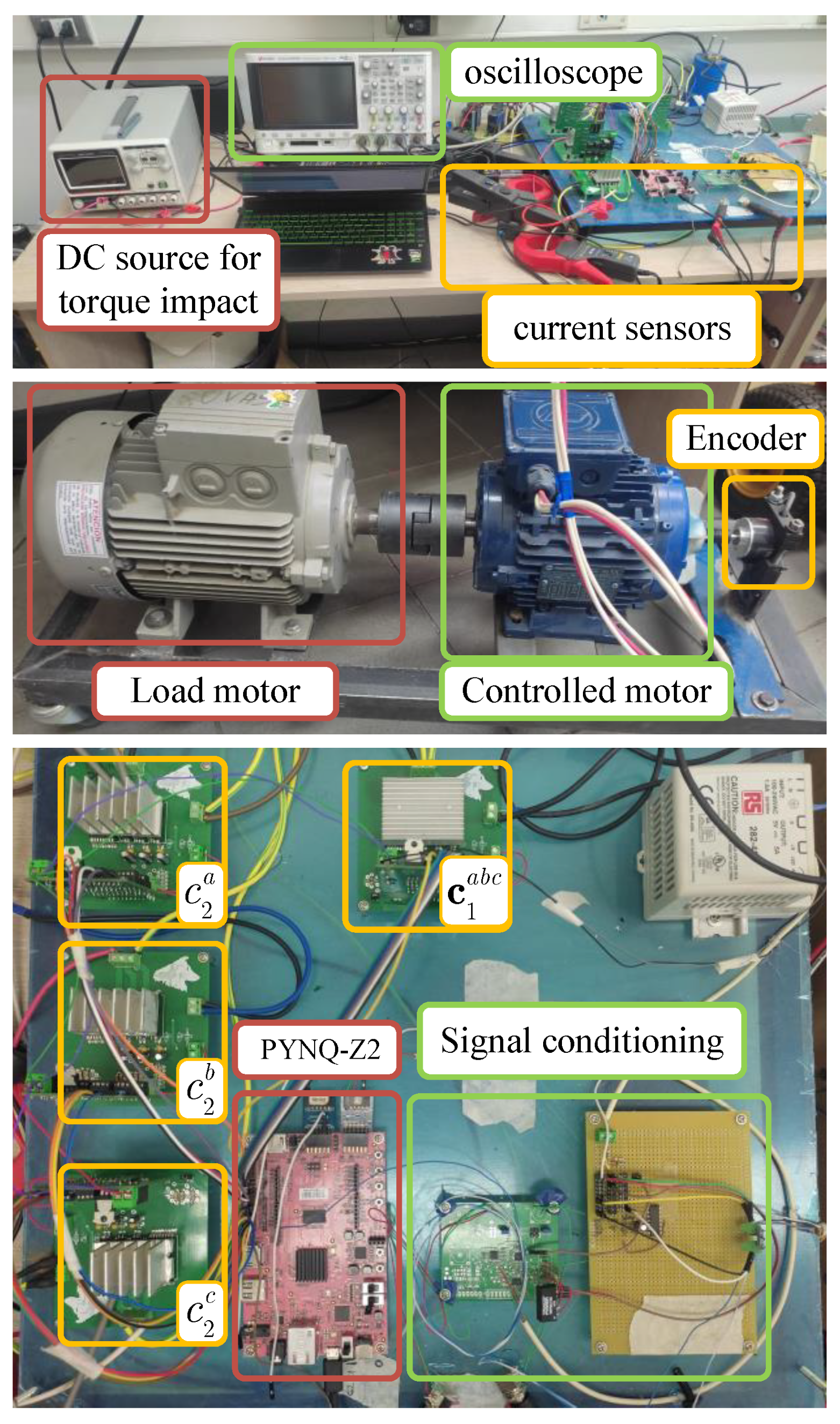
The control strategies described in the previous section are implemented in a five-level HCC feeding a three-phase induction motor (see Figure 3), with the parameters shown in Table 1. The experimental setup was built using the FSBB20CH60C module, which integrates IGBTs (600 V/20 A) with their respective gate driver, as shown in Figure 4. The DC-link voltages are 100 V and 50 V for the 2L-VSI and H-bridges, respectively, allowing for symmetric operation of the HCC.
The FCS-MPC strategies were implemented on an AMD PYNQ board based on the Zynq-7000 system-on-chip (SoC). This architecture integrates, in a single chip, a dual-core ARM Cortex-A9 processor with a Xilinx 7-series FPGA, enabling the implementation of the FCS-MPC strategies while considering all available states of the HCC, with a sampling time of 50 μs. Cheaper options like Texas Instruments LAUNCHXL-F28379D [50] do not have the required computing power, and more expensive options, like dSPACE MicroLabBox [39], meet the calculation requirements but its use is mainly restricted to a laboratory setting.
The strategies described in Section 4 are evaluated in both steady-state and dynamic regimes using the parameters provided in Table 2. The sampling time and target switching frequency are determined based on the previous literature [10,21,23,24], while the weighting factors are selected using the branch-and-bound method described in [51,52] to optimize algorithm performance. In the case of the notch filter, its parameters are calculated according to the recommendations of the original paper [14].
The performance of each strategy is assessed for current controller operation in an FOC scheme (see Figure 1), while the speed loop uses a PI regulator with K p = 0.11 , K i = 1.2 , a sampling frequency of 2 kHz, and a nominal speed reference (see Table 1).
The sampling frequency for all the evaluated strategies is 50 μs, equal to a sampling frequency of 20 kHz, except for conventional FCS-MPC. To achieve a fair comparison between strategies, these are tuned either to achieve a concentrated harmonic spectrum or an average switching frequency around 1 kHz depending on the features of each one; for instance, in the case of the PWM restriction strategy, the carrier frequency of the 2L-VSI and H-bridges that form the HCC topology are set to 1 kHz and 500 Hz, respectively. In the case of conventional FCS-MPC, the required switching frequency to achieve the same target average switching frequency is 5 kHz, which is four times less than that used in the other evaluated strategies.

5.1. Hardware Implementation

The five-level HCC topology has 512 available states (input values) that the FCS-MPC algorithm must evaluate to select the optimal input that minimizes the desired cost function. The high number of input values to be evaluated by the predictive algorithm results in a significant computational burden. To mitigate this issue, it is possible to either (i) employ simplifications in the predictive model or (ii) limit the number of states evaluated for successful controller implementation [7,8]. However, both solutions could potentially lead to a suboptimal solution for the optimization problem. To address this challenge and ensure a fair comparison of the algorithms under the same conditions, an AMD Zynq-7000 SoC is utilized [53]. This system allows for the utilization of all available states on the HCC with minimal timing constraints.
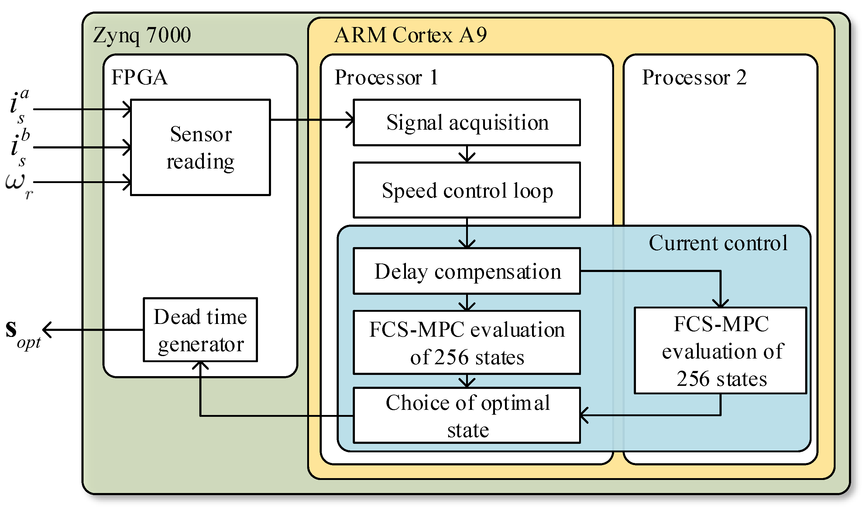
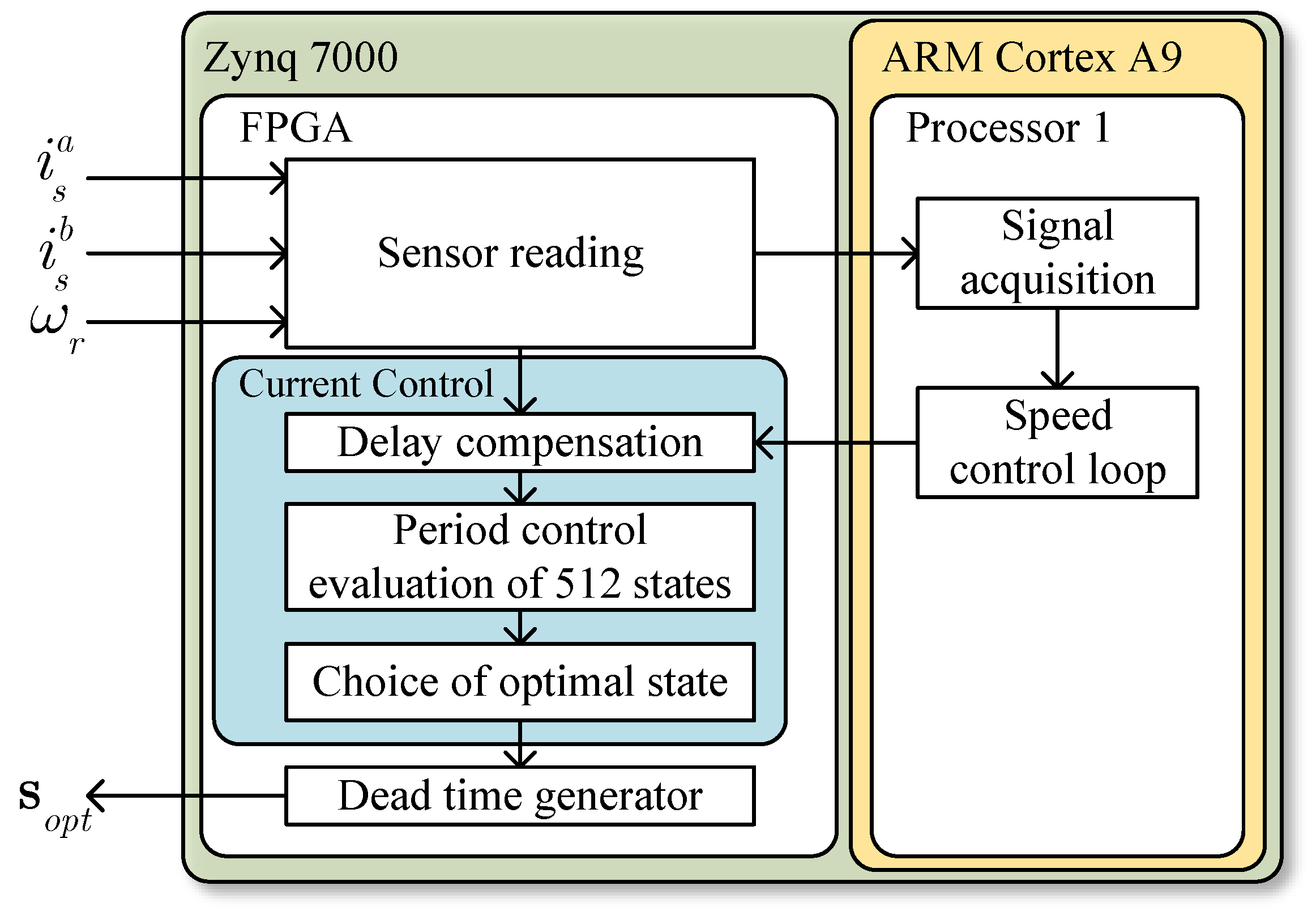
In this work, two approaches are proposed to implement high-computational-burden FCS-MPC algorithms on the Zynq-7000 SoC, utilizing both the FPGA and the embedded processor available on the chip. Figure 5 shows the first approach that uses dual-core ARM processors to solve the FCS-MPC algorithm. With this implementation, 256 states are evaluated in parallel on each processor, reducing the required time for half of the optimization problem. Input restriction, notch filter, and PWM restriction strategies use this approach. However, for the period control strategy, this hardware implementation does not meet the timing constraint required to achieve a sampling time of 50 μs, due to reasons that are discussed in Section 5.4 below. Therefore, the approach shown in Figure 6 is utilized. In this case, the period control algorithm is implemented directly on the Zynq-7000 FPGA using the High-Level Synthesis (HLS) tool of Vivado Xilinx, with a C language description [54]. In both approaches, AXI-Lite buses with a 32-bit register are used for data exchange between FPGA modules and ARM processors. Two AEMC Instruments SL261 current probes are used for motor current acquisition. Both current probes are connected to a signal conditioning board to match the measurements to the ADC’s input range. Signal acquisition uses the analog-to-digital converter AD7476A. The Zynq system on chip requires 1 μs to execute all measurements, while the converter’s gating signals are programmed with a dead time of 2 μs. An incremental encoder with a resolution of 1000 pulses per revolution performs rotor position measurement. This signal is acquired and processed in the FPGA to compute the motor speed ( ω r ). Figure 4 depicts the current probe, signal conditioning board, and encoder.

5.2. Steady-State Performance

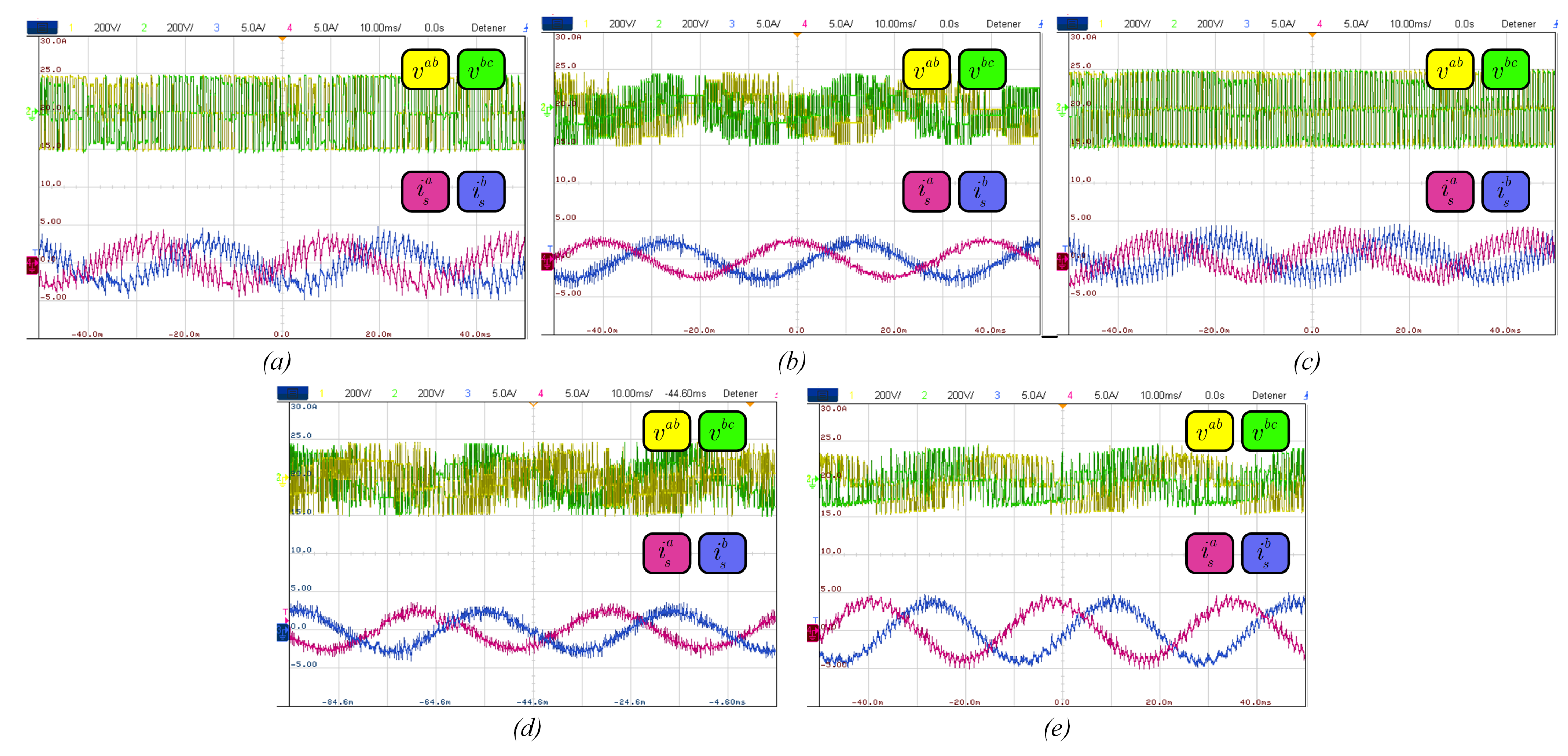
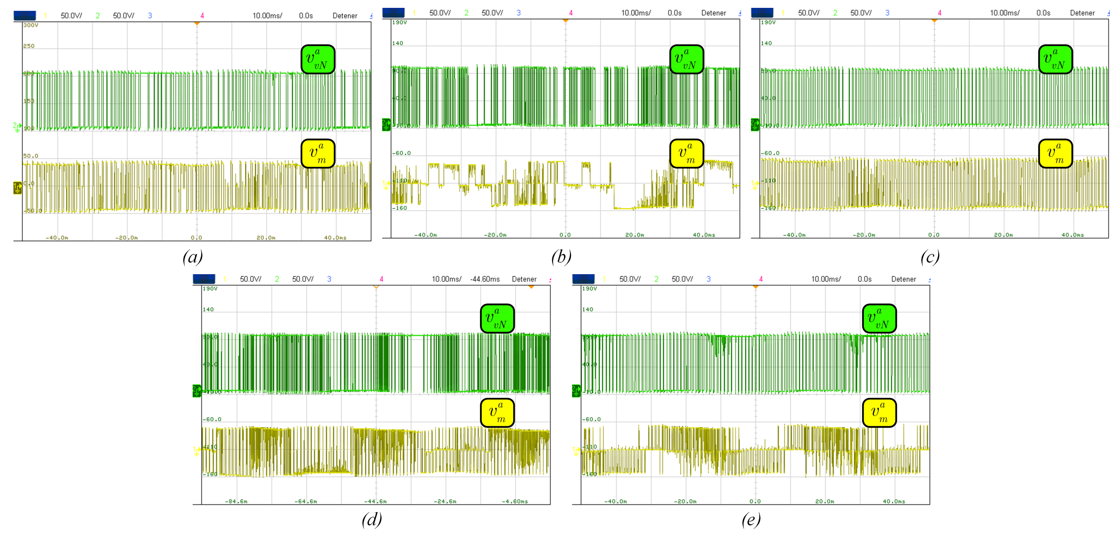
To verify the performance of the selected strategies for fixing or reducing the switching frequency, a steady-state regime analysis is performed. The strategies are implemented considering a nominal load torque of 1.338 Nm and a speed reference of 74.874 rad/s, except for the notch filter, whose load torque is 70 % of the nominal value, for reasons which will become apparent from the results.
Figure 7, Figure 8 and Figure 9 present the steady-state behavior of the evaluated strategies. All controllers, except for the notch filter-based strategy, maintain a steady-state error of less than 20 % . The notch filter strategy requires a wide bandwidth to concentrate the harmonic spectrum, which leads to an increase in the steady-state error. In this case, the error is equivalent to 67 % of the current reference for a load torque of T l = 0.7 T n o m . A lower load torque was used for the notch filter, as higher torque levels would compromise the machine’s orientation due to the increased error compared to the other strategies.
Table 3 presents a summary of the standard error mean (SEM) and mean square error (MSE) associated with each strategy. These indicators quantify the performance of the current reference tracking. While the SEM is related to the analysis of permanent error, the MSE allows for the quantification of the signal ripple in steady state. The results show that PWM restriction achieves an SEM 400 times less for i s d and 100 times less for i s q compared with the input restriction strategy, which is the second-best performing strategy. For MSE, the best performance is achieved for the input restriction with values 1.5 times less for i s d and 2.5 times less for i s q compared to the PWM restriction strategy, which is the second-best performing strategy. The input restriction control scheme exhibits lower MSE in contrast to PWM restriction because there is no imposition of a switching pattern in the converter inputs by the PWM stage. Instead, the optimal state is chosen considering the previously applied state, resulting in a signal with low ripple but with steady-state error. In contrast, PWM restriction introduces a higher ripple than input restriction due to the pattern imposition, but it leads to less steady-state error, resulting in a reduced SEM value.
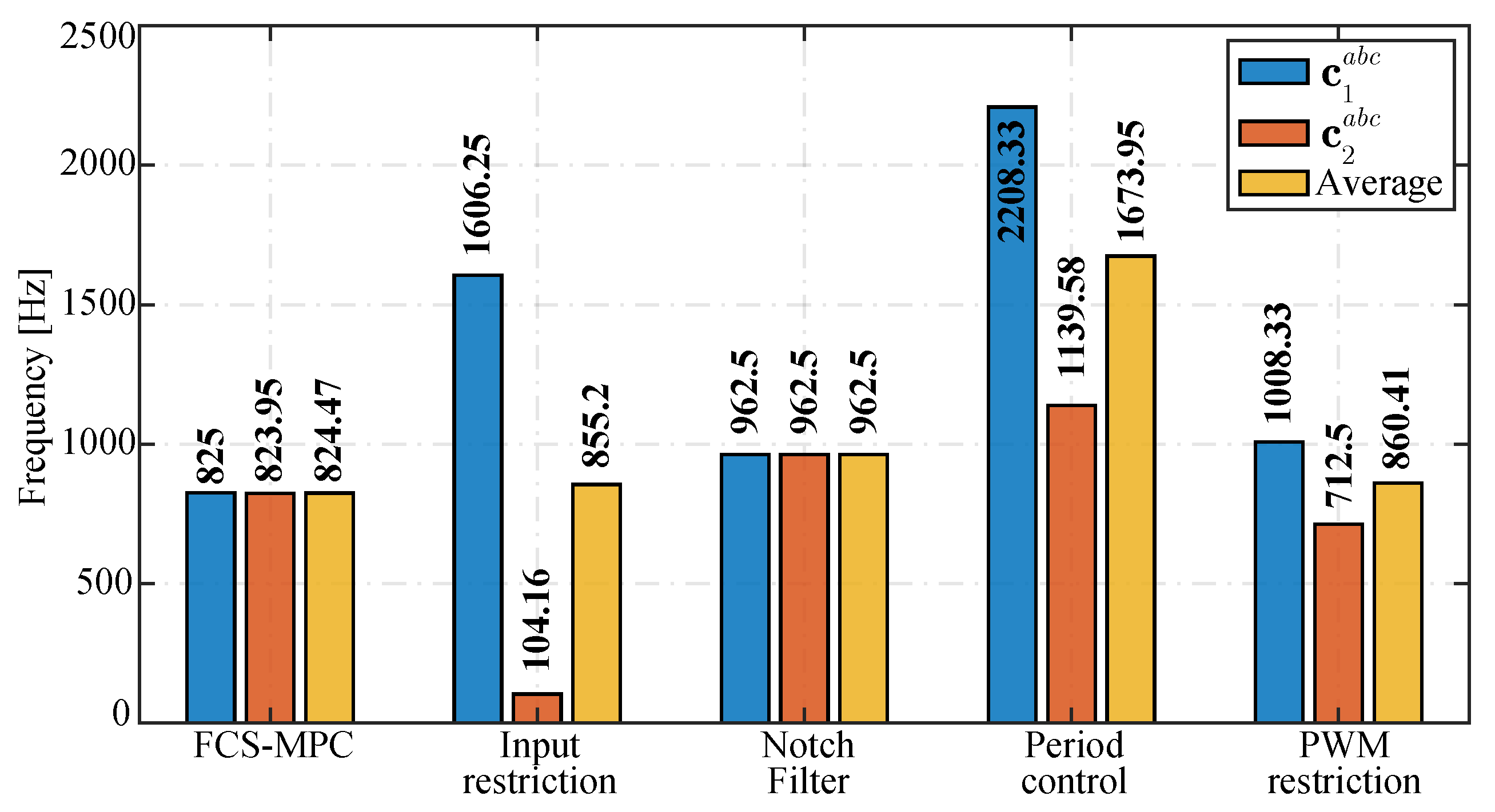
Figure 10 shows the harmonic spectra associated with the key waveforms of the system for the compared strategies. As previously mentioned, the control strategies are tuned to achieve an average switching frequency around 1 kHz. The results show that the best performance corresponds to notch filter and PWM restriction strategies, with average switching frequencies of 962.5 Hz and 860.4 Hz, respectively. Both strategies show a harmonic spectrum concentrated around the desired frequency of 1 kHz. Figure 11 summarizes the average switching frequency per semiconductor (ASFS) of each HCC module for each strategy. As can be seen, PWM restriction has a lower ASFS for H-bridge modules than the other strategies studied. This results from the unipolar modulation imposed by the control objective, which aims to follow the PWM pattern from phase-shift modulation. Therefore, the H-bridge semiconductors must commutate at half of the desired frequency to achieve the objective frequency.
The total harmonic distortion (THD) of key waveforms is presented in Table 4. The conventional FCS-MPC and notch filter strategies produce values 2 and 4 times higher than the other strategies for the i s a and v a b signals, respectively. For conventional FCS-MPC, this result is a consequence of the switching frequency reduction, which produces a harmonic spectrum displacement to low frequencies, increasing the THD value. In the case of the notch filter strategy, the same analysis can be made, where a large part of the harmonic components are concentrated around 1 kHz, resulting in a high THD, i.e., 486 % for v a b .
Concerning the power balance among the modules that constitute the HCC (see Table 4), the notch filter strategy achieves a balanced operation, with a difference equal to zero. The second-best result is achieved by the PWM restriction strategy, with a maximum difference between modules of 0.8 % . The advantage of this strategy is that power distribution among cells is ensured by the PWM stage when the DC link of each HCC module is equal. In contrast, for the input restriction strategy the results depend on the system operating point and are not guaranteed by the strategy itself.

5.3. Dynamic Performance

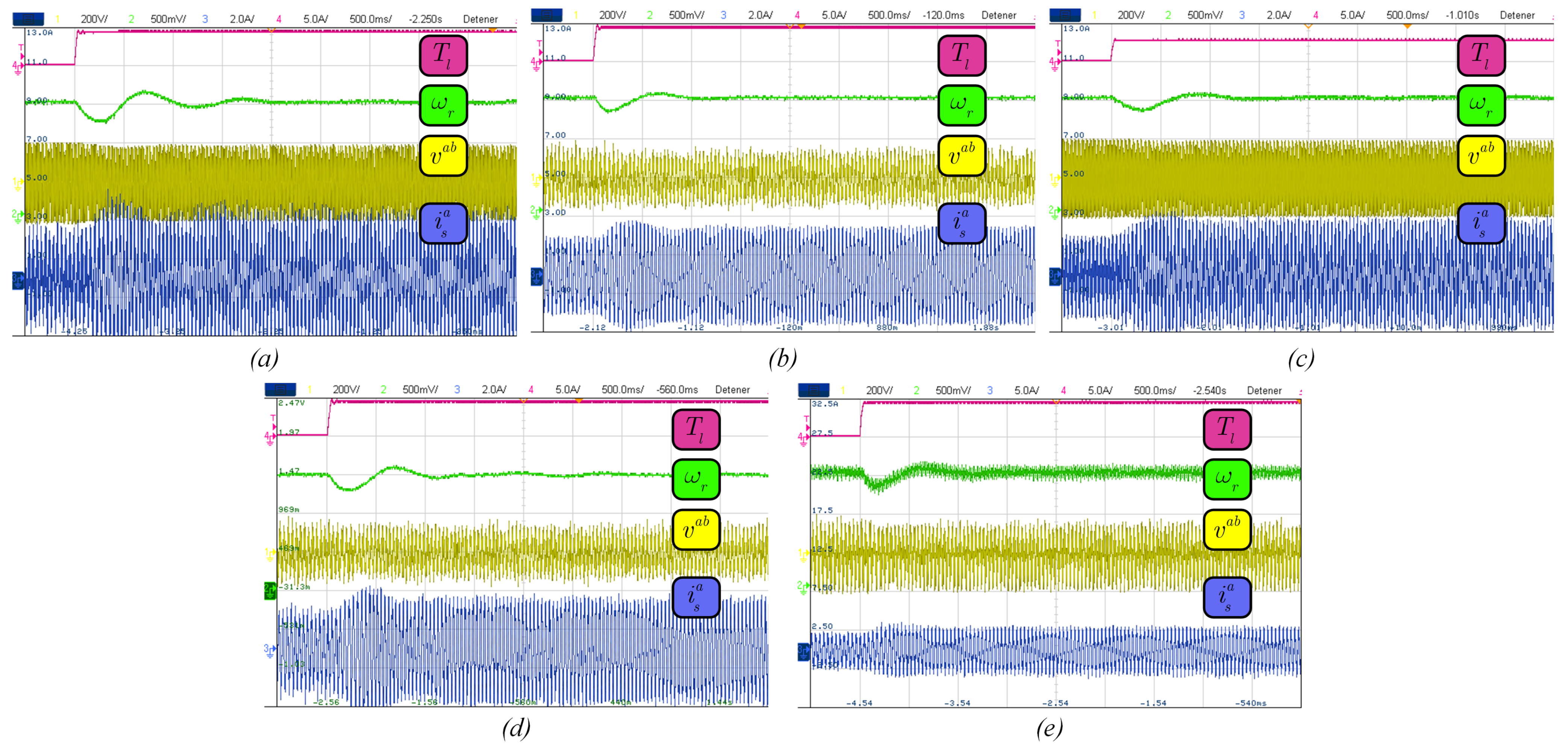
To evaluate the dynamic performance of the FCS-MPC strategies under study, a load torque change from T l = 0 to T l = 0.7 T nom is applied to all strategies, except for the notch filter one. In the notch filter strategy, the change applied is from T l = 0 to T l = 0.5 T nom to prevent the loss of rotor flux orientation (see Figure 12) due to the high steady-state error that results with this strategy, as described in Section 5.2.
Figure 13 shows that all the evaluated strategies can maintain the motor speed with a steady-state error of less than 1 % after the load torque step, a result that is attributed to the PI controller used in the speed loop. Input restriction, period control, and PWM restriction reach the reference speed in approximately 0.5 s, while conventional FCS-MPC takes about 1 s. Despite using the same parameters for the speed-loop PI controller, the conventional FCS-MPC exhibits the slowest dynamic performance due to the higher sampling time (Ts = 200 μs) used to reduce the average switching frequency of the converter. However, the rest of the evaluated strategies, implemented with the same sampling time of Ts = 50 μs, achieve similar dynamic performance.

5.4. Computational Cost

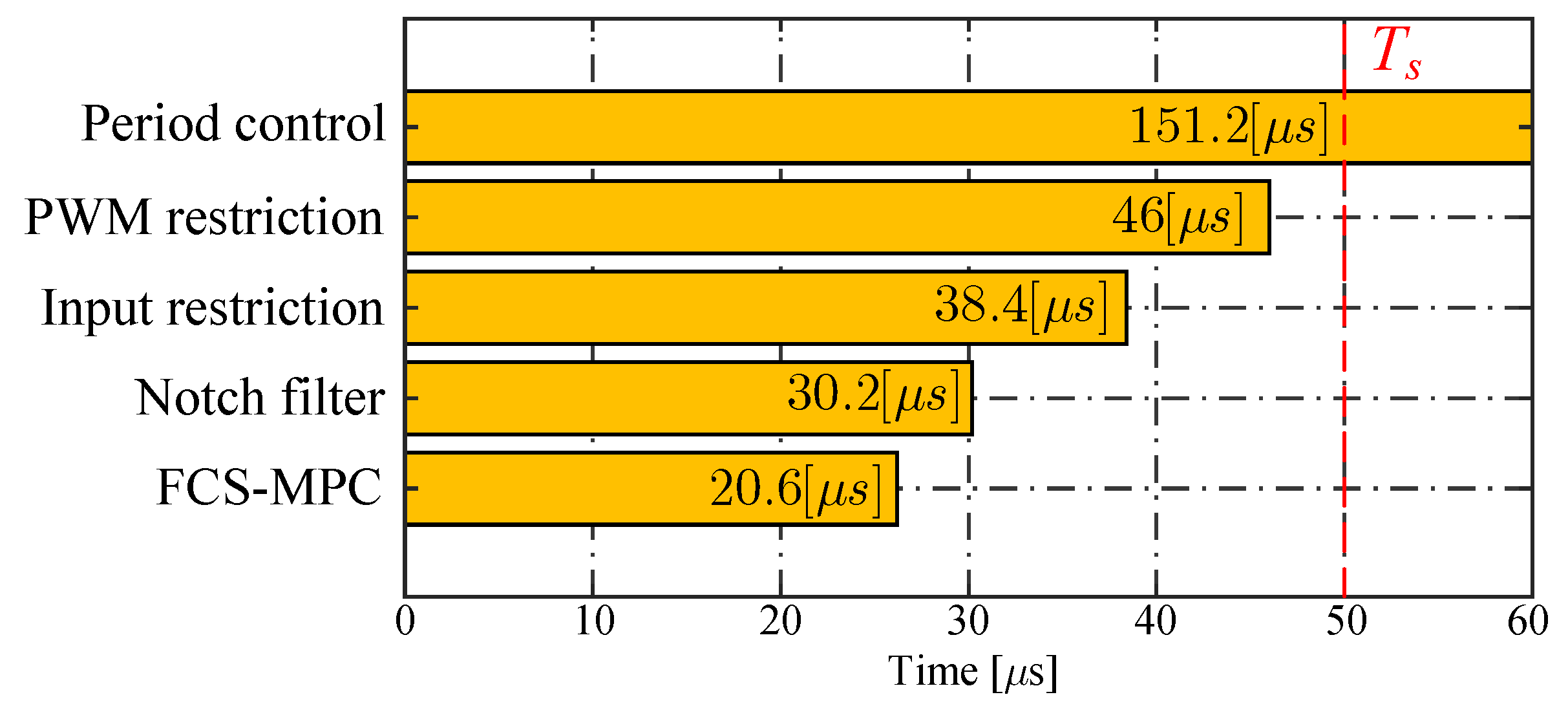
Figure 14 shows the execution time for each strategy using the proposed control framework based on the Zynq-7000, as illustrated in Figure 5. Compared with the conventional strategy, the PWM restriction and period control strategies present 72 % and 468 % higher computational costs, respectively. The period control strategy exhibits an execution time that exceeds the required sampling time by 300 % , rendering its implementation unfeasible using the control architecture depicted in Figure 5. The high computational burden of the period control strategy arises from the need to evaluate both the falling- and rising-edge transitions of each semiconductor for every valid state of the converter (see Table 5). Therefore, for a five-level HCC converter, it is necessary to evaluate nine switches for each of the 512 valid converter states. To be able to perform a dynamic and steady-state regime comparison with the other strategies, the period control strategy is implemented using the FPGA of Zynq-7000, as shown in Figure 6, resulting in an execution time of 20 μs. This result is 86.7 % lower than using only the ARM processor, demonstrating that it is possible to implement high-computational-burden algorithms through the well-known C language using available off-the-shelf HDL design tools. Table 6 summarizes the results obtained from the experimental evaluation of the selected strategies.

6. Conclusions

This work has presented a comprehensive comparison among strategies that reduce or fix the switching frequency in FCS-MPC by modifying the cost function of the predictive scheme. In contrast to previous works, which usually rely on the well-known two-level converter topology and a simple resistive–inductive load to present the strategies, the study has been carried out using a multilevel HCC converter feeding an induction motor, providing a more complex and realistic scenario. For a fair comparison, all available states of the HCC were used in the FCS-MPC optimization stage of each strategy. This has higher computational requirements than previous works, and to overcome this problem, a cost-effective control implementation solution based on Zynq-7000 SoC with high computational capacity has been proposed. The results show the feasibility of using the aforementioned solution for this application, allowing the implementation of the strategies using the 512 available inputs without hitting hard timing constraints.
Regarding the study of the different strategies, the results show that the strategies proposed to improve the steady-state behavior of FCS-MPC in two-level converters can be successfully implemented in multilevel topologies. However, strategies that include the topology structure in their formulation, such as PWM restriction, allow for taking advantage of the features of the multilevel topology, such as reduced switching frequency, less semiconductor stress, and a lower d v / d t , among others. In particular, from the results it can be concluded that the PWM restriction strategy presents the best performance at steady state considering features such as steady-state error, switching frequency, harmonic dispersion, and power sharing among the converter cells. The other strategies evaluated, with the exception of input restriction, encounter issues concerning the trade-off between steady-state error and harmonic concentration that require elaborate tuning of weighing factors to prevent loss of machine orientation for the FOC strategy, a notable drawback in this application.
Based on the results of this work, it is expected that new control strategies based on period control, notch filter, and PWM restriction can be developed to enable their implementation in more complex multilevel topologies. These strategies should be designed to have an affordable computational burden while offering superior performance in both steady-state and transient regimes. Furthermore, it is expected that future research could evaluate these strategies alongside others that do not necessarily operate under the same principles, particularly modulated schemes such as OSV-MPC, M2PC, and CCS-MPC, each of which presents its own advantages and challenges.

Author Contributions

Conceptualization, M.E.A. and R.O.R.; methodology, M.E.A.; software, M.E.A. and R.O.R.; validation, R.O.R. and C.R.B.; formal analysis, M.E.A.; investigation, M.E.A.; resources, R.O.R.; data curation, M.E.A. and F.P.U.-G.; writing—original draft preparation, M.E.A.; writing—review and editing, R.O.R., F.A.V. and J.R.E.; visualization, C.R.B. and F.A.V.; supervision, R.O.R.; project administration, R.O.R.; funding acquisition, R.O.R. All authors have read and agreed to the published version of the manuscript.

Funding

This research was funded by the ANID-FONDECYT Initiation Project grant number 11241077 (ANID/FONDECYT Iniciación/11241077).

Data Availability Statement

Data are contained within the article.

Acknowledgments

The support of the Energy Conversion Technology Center of the University of Talca is gratefully acknowledged.

Conflicts of Interest

The authors declare no conflicts of interest.

References

  1. Abu-Rub, H.; Holtz, J.; Rodriguez, J.; Baoming, G. Medium-voltage multilevel converters State of the art, challenges, and requirements in Industrial applications. IEEE Trans. Ind. Electron. 2010, 57, 2581–2596. [Google Scholar] [CrossRef]
  2. Kouro, S.; Malinowski, M.; Gopakumar, K.; Pou, J.; Franquelo, L.G.; Wu, B.; Rodriguez, J.; Pérez, M.A.; Leon, J.I. Recent Advances and Industrial Applications of Multilevel Converters. IEEE Trans. Ind. Electron. 2010, 57, 2553–2580. [Google Scholar] [CrossRef]
  3. Rodriguez, J.; Bernet, S.; Wu, B.; Pontt, J.o.; Kouro, S. Multilevel Voltage-Source-Converter Topologies for Industrial Medium-Voltage Drives. IEEE Trans. Ind. Electron. 2007, 54, 2930–2945. [Google Scholar] [CrossRef]
  4. Du, Z.; Ozpineci, B.; Tolbert, L.M.; Chiasson, J.N. Inductorless DC-AC cascaded H-bridge multilevel boost inverter for electric/hybrid electric vehicle applications. In Proceedings of the IEEE Industry Applications Society, New Orleans, LA, USA, 23–27 September 2007; pp. 603–608. [Google Scholar] [CrossRef]
  5. Su, Y.C.; Wu, P.H.; Cheng, P.T. Design and Evaluation of a Control Scheme for the Hybrid Cascaded Converter in Grid Applications. IEEE Trans. Power Electron. 2020, 35, 3139–3147. [Google Scholar] [CrossRef]
  6. Bisht, N.; Das, A. A Circuit Topology of Cascaded H-Bridge STATCOM to Operate with Multiple Faulty Bypassed Cells. IEEE Trans. Ind. Appl. 2021, 57, 5345–5355. [Google Scholar] [CrossRef]
  7. Wiatr, P.; Kazmierkowski, M.P. Hybrid 5-level cascaded H-Bridge converter with model predictive controller. In Proceedings of the 2016 IEEE International Power Electronics and Motion Control Conference (PEMC), Varna, Bulgaria, 25–28 September 2016; pp. 128–132. [Google Scholar] [CrossRef]
  8. Wiatr, P.; Kryński, A. Model predictive control of multilevel cascaded converter with boosting capability—Experimental results. Bull. Pol. Acad. Sci. Tech. Sci. 2017, 65, 589–599. [Google Scholar] [CrossRef]
  9. Kouro, S.; Cortés, P.; Vargas, R.; Ammann, U.; Rodriguez, J. Model predictive control—A simple and powerful method to control power converters. IEEE Trans. Ind. Electron. 2009, 56, 1826–1838. [Google Scholar] [CrossRef]
  10. Vazquez, S.; Rodriguez, J.; Rivera, M.; Franquelo, L.G.; Norambuena, M. Model Predictive Control for Power Converters and Drives: Advances and Trends. IEEE Trans. Ind. Electron. 2017, 64, 935–947. [Google Scholar] [CrossRef]
  11. Cortés, P.; Kazmierkowski, M.P.; Kennel, R.M.; Quevedo, D.E.; Rodriguez, J. Predictive control in power electronics and drives. IEEE Trans. Ind. Electron. 2008, 55, 4312–4324. [Google Scholar] [CrossRef]
  12. Geyer, T.; Papafotiou, G.; Morari, M. Model predictive direct torque control—Part I: Concept, algorithm, and analysis. IEEE Trans. Ind. Electron. 2009, 56, 1894–1905. [Google Scholar] [CrossRef]
  13. Yaramasu, V.; Rivera, M.; Wu, B.; Rodriguez, J. Model predictive current control of two-level four-leg inverters—Part i: Concept, algorithm, and simulation analysis. IEEE Trans. Power Electron. 2013, 28, 3459–3468. [Google Scholar] [CrossRef]
  14. Cortés, P.; Rodríguez, J.; Quevedo, D.E.; Silva, C. Predictive Current Control Strategy with Imposed Load Current Spectrum. IEEE Trans. Power Electron. 2008, 23, 612–618. [Google Scholar] [CrossRef]
  15. Ramirez, R.O.; Baier, C.R.; Villarroel, F.; Espinoza, J.R.; Pou, J.; Rodriguez, J. A Hybrid FCS-MPC with Low and Fixed Switching Frequency without Steady-State Error Applied to a Grid-Connected CHB Inverter. IEEE Access 2020, 8, 223637–223651. [Google Scholar] [CrossRef]
  16. Moosavi, M.; Farivar, G.; Iman-Eini, H.; Shekarabi, S.M. A voltage balancing strategy with extended operating region for cascaded H-bridge converters. IEEE Trans. Power Electron. 2014, 29, 5044–5053. [Google Scholar] [CrossRef]
  17. Yu, Y.; Konstantinou, G.; Hredzak, B.; Agelidis, V.G. Power Balance Optimization of Cascaded H-Bridge Multilevel Converters for Large-Scale Photovoltaic Integration. IEEE Trans. Power Electron. 2016, 31, 1108–1120. [Google Scholar] [CrossRef]
  18. Zhang, Y.; Yuan, X.; Wu, X.; Yuan, Y.; Zhou, J. Parallel Implementation of Model Predictive Control for Multilevel Cascaded H-Bridge STATCOM With Linear Complexity. IEEE Trans. Ind. Electron. 2020, 67, 832–841. [Google Scholar] [CrossRef]
  19. Holtz, J. Advanced PWM and Predictive Control-An Overview. IEEE Trans. Ind. Electron. 2016, 63, 3837–3844. [Google Scholar] [CrossRef]
  20. Harbi, I.; Rodriguez, J.; Liegmann, E.; Makhamreh, H.; Heldwein, M.L.; Novak, M.; Rossi, M.; Abdelrahem, M.; Trabelsi, M.; Ahmed, M.; et al. Model-Predictive Control of Multilevel Inverters: Challenges, Recent Advances, and Trends. IEEE Trans. Power Electron. 2023, 38, 10845–10868. [Google Scholar] [CrossRef]
  21. Tarisciotti, L.; Zanchetta, P.; Watson, A.; Clare, J.C.; Degano, M.; Bifaretti, S. Modulated Model Predictive Control for a Three-Phase Active Rectifier. IEEE Trans. Ind. Appl. 2015, 51, 1610–1620. [Google Scholar] [CrossRef]
  22. Rivera, M.; Perez, M.; Baier, C.; Munoz, J.; Yaramasu, V.; Wu, B.; Tarisciotti, L.; Zanchetta, P.; Wheeler, P. Predictive Current Control with fixed switching frequency for an NPC converter. In Proceedings of the IEEE International Symposium on Industrial Electronics, Buzios, Brazil, 3–5 June 2015; pp. 1034–1039. [Google Scholar] [CrossRef]
  23. Donoso, F.; Mora, A.; Cardenas, R.; Angulo, A.; Saez, D.; Rivera, M. Finite-Set Model-Predictive Control Strategies for a 3L-NPC Inverter Operating with Fixed Switching Frequency. IEEE Trans. Ind. Electron. 2018, 65, 3954–3965. [Google Scholar] [CrossRef]
  24. Alexandrou, A.D.; Adamopoulos, N.K.; Kladas, A.G. Development of a Constant Switching Frequency Deadbeat Predictive Control Technique for Field-Oriented Synchronous Permanent-Magnet Motor Drive. IEEE Trans. Ind. Electron. 2016, 63, 5167–5175. [Google Scholar] [CrossRef]
  25. Aguirre, M.; Kouro, S.; Rojas, C.A.; Rodriguez, J.; Leon, J.I. Switching Frequency Regulation for FCS-MPC Based on a Period Control Approach. IEEE Trans. Ind. Electron. 2018, 65, 5764–5773. [Google Scholar] [CrossRef]
  26. Aguirre, M.; Kouro, S.; Rojas, C.A.; Vazquez, S. Enhanced Switching Frequency Control in FCS-MPC for Power Converters. IEEE Trans. Ind. Electron. 2021, 68, 2470–2479. [Google Scholar] [CrossRef]
  27. Tomlinson, M.; Mouton, H.D.T.; Kennel, R.; Stolze, P. A Fixed Switching Frequency Scheme for Finite-Control-Set Model Predictive Control-Concept and Algorithm. IEEE Trans. Ind. Electron. 2016, 63, 7662–7670. [Google Scholar] [CrossRef]
  28. Urrutia, M.; Cárdenas, R.; Clare, J.C.; Watson, A. Circulating Current Control for the Modular Multilevel Matrix Converter Based on Model Predictive Control. IEEE J. Emerg. Sel. Top. Power Electron. 2021, 9, 6069–6085. [Google Scholar] [CrossRef]
  29. Urrutia, M.; Cárdenas, R.; Clare, J.C.; Díaz, M.; Watson, A. Continuous Set Model Predictive Control for Energy Management of Modular Multilevel Matrix Converters. IEEE Trans. Power Electron. 2022, 37, 5731–5748. [Google Scholar] [CrossRef]
  30. Zhang, B.; Wu, W.; Chen, Y.; Gao, N.; Chen, J.; Koutroulis, E.; Chung, H.S.H.; Liserre, M.; Blaabjerg, F. Enhanced Deadbeat Control-Model Predictive Control Strategy of Grid-Connected Power Converters With LCL Filter. IEEE Trans. Ind. Electron. 2024, 71, 15826–15834. [Google Scholar] [CrossRef]
  31. Gong, Z.; Zhang, L.; Liu, C.; Yang, Z.; Wu, X. Deadbeat Model Predictive Control for Modular Multilevel Matrix Converter Under Unbalanced Grid Conditions. IEEE Trans. Power Electron. 2025, 40, 1258–1271. [Google Scholar] [CrossRef]
  32. Wang, Q.; Yu, H.; Li, C.; Lang, X.; Yeoh, S.S.; Yang, T.; Rivera, M.; Bozhko, S.; Wheeler, P. A Low-Complexity Optimal Switching Time-Modulated Model-Predictive Control for PMSM With Three-Level NPC Converter. IEEE Trans. Transp. Electrif. 2020, 6, 1188–1198. [Google Scholar] [CrossRef]
  33. Harbi, I.; Ahmed, M.; Hackl, C.M.; Rodriguez, J.; Kennel, R.; Abdelrahem, M. Low-Complexity Dual-Vector Model Predictive Control for Single-Phase Nine-Level ANPC-Based Converter. IEEE Trans. Power Electron. 2023, 38, 2956–2971. [Google Scholar] [CrossRef]
  34. Schuetz, D.; Osório, C.R.D.; Maccari, L.A.; Lima, D.M.; Carnielutti, F.d.M.; Montagner, V.F.; Pinheiro, H. Space Vector Modulated Model Predictive Control for Grid-Tied Converters. IEEE Trans. Ind. Inform. 2023, 19, 414–425. [Google Scholar] [CrossRef]
  35. Matias, M.A.; Vazquez, S.; Wilson-Veas, A.H.; Kouro, S.; Rojas, C.A.; Leon, J.I.; Franquelo, L.G. Extended Period Control Approach FCS-MPC for Three Phase NPC Power Converters. IEEE Trans. Power Electron. 2025, 40, 4927–4937. [Google Scholar] [CrossRef]
  36. Baier, C.R.; Ramirez, R.O.; Marciel, E.I.; Hernández, J.C.; Melín, P.E.; Espinosa, E.E. FCS-MPC Without Steady-State Error Applied to a Grid-Connected Cascaded H-Bridge Multilevel Inverter. IEEE Trans. Power Electron. 2021, 36, 11785–11799. [Google Scholar] [CrossRef]
  37. Aguirre, M.; Vazquez, S.; Alcaide, A.M.; Portillo, R.; Kouro, S.; Leon, J.I.; Franquelo, L.G. Period Control Approach Finite Control Set Model Predictive Control Switching Phase Control for Interleaved DC/DC Converters. IEEE Trans. Ind. Electron. 2024, 71, 8304–8312. [Google Scholar] [CrossRef]
  38. OPAL-RT. OP4512 SIMULATOR. 2024. Available online: https://www.opal-rt.com/simulator-platform-op4512/ (accessed on 3 January 2025).
  39. dSPACE. MicroLabBox. 2024. Available online: https://www.dspace.com/en/pub/home/products/hw/microlabbox.cfm (accessed on 3 January 2025).
  40. Plexim. RT Box 1. 2024. Available online: https://www.plexim.com/products/rt_box/rt_box_1 (accessed on 3 January 2025).
  41. Abughalieh, K.M.; Alawneh, S.G. A Survey of Parallel Implementations for Model Predictive Control. IEEE Access 2019, 7, 34348–34360. [Google Scholar] [CrossRef]
  42. Xu, F.; Guo, Z.; Chen, H.; Ji, D.; Qu, T. A Custom Parallel Hardware Architecture of Nonlinear Model-Predictive Control on FPGA. IEEE Trans. Ind. Electron. 2022, 69, 11569–11579. [Google Scholar] [CrossRef]
  43. MarketsandMarkets. Electric Motor Market Report. Latest Industry Trends 2026. 2025. Available online: https://www.marketsandmarkets.com/Market-Reports/electric-motor-market-alternative-fuel-vehicles-717.html (accessed on 3 January 2025).
  44. Williamson, S.S.; Rathore, A.K.; Musavi, F. Industrial Electronics for Electric Transportation: Current State-of-the-Art and Future Challenges. IEEE Trans. Ind. Electron. 2015, 62, 3021–3032. [Google Scholar] [CrossRef]
  45. Rodriguez, J.; Cortes, P. Predictive Control of Power Converters and Electrical Drives; John Wiley & Sons: Hoboken, NJ, USA, 2012. [Google Scholar]
  46. Cortes, P.; Rodriguez, J.; Silva, C.; Flores, A. Delay compensation in model predictive current control of a three-phase inverter. IEEE Trans. Ind. Electron. 2012, 59, 1323–1325. [Google Scholar] [CrossRef]
  47. Wang, G.; Zhou, H.; Zhao, N.; Li, C.; Xu, D. Sensorless Control of IPMSM Drives Using a Pseudo-Random Phase-Switching Fixed-Frequency Signal Injection Scheme. IEEE Trans. Ind. Electron. 2018, 65, 7660–7671. [Google Scholar] [CrossRef]
  48. Leon, J.I.; Vazquez, S.; Franquelo, L.G. Multilevel Converters: Control and Modulation Techniques for Their Operation and Industrial Applications. Proc. IEEE 2017, 105, 2066–2081. [Google Scholar] [CrossRef]
  49. Holmes, D.G.; Lipo, T.A. Pulse Width Modulation for Power Converters; IEEE: Piscataway, NJ, USA, 2003; p. 744. [Google Scholar] [CrossRef]
  50. Instruments, T. F28379D LaunchPad development kit for C2000 Delfino MCU. 2024. Available online: https://www.ti.com/tool/LAUNCHXL-F28379D (accessed on 3 January 2025).
  51. Cortés, P.; Kouro, S.; Rocca, B.L.; Vargas, R.; Rodríguez, J.; León, J.I.; Vazquez, S.; Franquelo, L.G. Guidelines for weighting factors design in model predictive control of power converters and drives. In Proceedings of the IEEE International Conference on Industrial Technology, Churchill, VIC, Australia, 10–13 February 2009. [Google Scholar] [CrossRef]
  52. Karamanakos, P.; Geyer, T. Guidelines for the Design of Finite Control Set Model Predictive Controllers. IEEE Trans. Power Electron. 2019, 8993, 7434–7450. [Google Scholar] [CrossRef]
  53. Xilinx, A. XUP PYNQ-Z2. 2024. Available online: https://www.amd.com/es/corporate/university-program/aup-boards/pynq-z2.html (accessed on 3 January 2025).
  54. Xilinx, A. High Level Design Features. 2024. Available online: https://www.xilinx.com/products/design-tools/vivado/high-level-design.html (accessed on 3 January 2025).
Figure 1. General scheme of the system.
Processes 13 01214 g001
Figure 2. Scheme of FCS-MPC.
Processes 13 01214 g002
Figure 3. Setup scheme.
Processes 13 01214 g003
Figure 4. Experimental setup.
Processes 13 01214 g004
Figure 5. Control implementation in PYNQ-Z2.
Processes 13 01214 g005
Figure 6. Control implementation in PYNQ-Z2 for period control.
Processes 13 01214 g006
Figure 7. Steady-state behavior for a sampling frequency of 20 kHz: (a) Conventional FCS-MPC ( f s = 5 kHz); (b) input restriction; (c) notch filter; (d) period control; (e) PWM restriction.
Processes 13 01214 g007
Figure 8. Steady-state behavior in d q axes for a sampling frequency of 20 kHz: (a) Conventional FCS-MPC ( f s = 5 kHz); (b) input restriction; (c) notch filter; (d) period control; (e) PWM restriction.
Processes 13 01214 g008
Figure 9. Steady-state behavior of each module at a sampling frequency of 20 kHz: (a) Conventional FCS-MPC ( f s = 5 kHz); (b) input restriction; (c) notch filter; (d) period control; (e) PWM restriction.
Processes 13 01214 g009
Figure 10. Harmonic spectrum for a sampling frequency of 20 kHz: (a) Conventional FCS-MPC ( f s = 5 kHz); (b) input restriction; (c) notch filter; (d) period control; (e) PWM restriction.
Processes 13 01214 g010
Figure 11. Average switching frequency (calculated in two periods).
Processes 13 01214 g011
Figure 12. Torque impact for notch filter strategy for a sampling frequency of 20 kHz.
Processes 13 01214 g012
Figure 13. Behavior under torque impact for a sampling frequency of 20 kHz: (a) Conventional FCS-MPC ( f s = 5 kHz); (b) input restriction; (c) notch filter; (d) period control; (e) PWM restriction.
Processes 13 01214 g013
Figure 14. Execution time of each strategy.
Processes 13 01214 g014
Table 1. Motor parameters.
ParameterDescriptionValues of Controlled MotorValues of Load Motor
R s Stator resistance 1.817 Ω 6.2 Ω
R r Rotor resistance 1.4723 Ω 5.04 Ω
L s Stator inductance 0.1413  H 0.0328  H
L r Rotor inductance 0.1413  H 0.0328  H
L o Magnetizing inductance0.1175 H 0.538  H
JMoment of inertia0.05 kg·m20.1 kg·m2
BInertia coefficient0.005 Nm/s0.005 Nm/s
pNumber of pole pairs22
Nominal values
V n o m Voltage190 V400 V
f n o m Frequency25 Hz50 Hz
ω n o m Speed74.874 rad/s148.7 rad/s
i n o m a b c Current4 A 6.4  A
i n o m d Current d 3.065  A 5.838  A
i n o m q Current q 4.288  A 9.131  A
T n o m Torque1.338 Nm13.312 Nm
Table 2. Control strategy parameters.
ParameterDescriptionValue
Conventional FCS-MPC
T s Sampling time200 μs *
Input restriction
T s Sampling time50 μs
λ Weighting factor 0.06
Notch filter
T s Sampling time50 μs
b 1 Filter coefficient 1.442
b 2 Filter coefficient 0.5265
a 0 Filter coefficient 1.0633
a 1 Filter coefficient 1.442
a 2 Filter coefficient 1.0633
Period control
T s Sampling time50 μs
λ Weighting factor 0.077
T r Period reference1 ms (40 p.u.)
PWM restriction
T s Sampling time50 μs
λ Weighting factor2
K p Proportional gain 58.6325
K i Integral gain 4.5132 · 10 5
f p H Carrier frequency of H-bridge500 Hz (20 p.u.) **
f p v Carrier frequency of 2L-VSI1000 Hz (40 p.u.) **
* For equivalent average switching frequency of 1 kHz. ** Both required for total switching frequency of 1 kHz.
Table 3. SEM and MSE summary.
Standard Error MeanMean Square Error
i s d i s q i s a ω r i s d i s q i s a ω r
FCS-MPC 0.1965 1.0464 0.3269 0.214 1.8573 3.1541 1.1528 0.203
Input restriction 0.0898 0.1085 0.04317 0.043 0.2266 0.1925 0.0699 0.125
Notch filter 1.3123 2.2697 0.8534 0.135 3.5729 6.8215 2.4387 0.08
Period control 0.0255 0.367 0.148 0.141 0.2736 0.4671 0.01292 0.08
PWM restriction 2.1651 · 10 4 0.0012 0.0104 0.132 0.3295 0.4434 0.1723 0.24
Table 4. THD and amplitude at fundamental frequency (25 Hz): summary.
i s a v ab v vN a v m a
THD (%)Amp.THD (%)Amp.THD (%)Amp.THD (%)Amp.
FCS-MPC 47.83 2.941 229.38 91.52 247.42 26.46 236.54 27.07
Input restriction 14.39 2.627 85.39 107.3 196.53 31.82 89.27 32.06
Notch filter 99.36 1.298 486.82 43.25 536.35 12.96 536.35 12.96
Period control 16.65 2.669 101.45 113.7 167.84 36.01 140.99 37.61
PWM restriction 19.22 3.923 101.22 112.7 176.48 33.78 103.38 34.07
Table 5. Summary of number of calculations per strategy.
Before OptimizationDuring Optimization
SumMult.Comp.SumMult.Comp.Total
FCS-MPC8140340 22 + 7 · 2 N
Input restriction8140 4 + ( N 1 ) 5N 22 + 2 N ( 8 + 2 N )
Notch filter14220560 36 + 11 · 2 N
Period control 8 + 2 N 14 + 2 N 2 N 3 + 4 N 5 + 2 N 2 N 22 + 6 N + 2 N ( 8 + 8 N )
PWM restriction1722N44N 39 + N + 2 N ( 8 + N )
Where N is the number of evaluated switches.
Table 6. Discussion summary.
FCS-MPCInput RestrictionNotch FilterPeriod ControlPWM Restriction
Switching frequencyDependent on T s * Dependent on weight factorDependent on the filter parametersDependent on weight factorDependent on carrier frequency ✓
Harmonic spectrumSpreadSpreadConcentrated ✓Concentrated ✓Concentrated ✓
Power distributionNoNoNoNoYes ✓
Computational costLow ✓MediumLow ✓Very highMedium
Standard mean errorMediumLow ✓HighMediumVery low ✓
Mean square errorHighLow ✓Very highLow ✓Low ✓
Parameters to tune01Dependent on order filter13
* Maintaining a fixed T s .
Disclaimer/Publisher’s Note: The statements, opinions and data contained in all publications are solely those of the individual author(s) and contributor(s) and not of MDPI and/or the editor(s). MDPI and/or the editor(s) disclaim responsibility for any injury to people or property resulting from any ideas, methods, instructions or products referred to in the content.