Article

Experimental Study on Combustion Characteristics of Methane Vertical Jet Flame

1
CNPC Engineering Technology R&D Company Limited, Beijing 102206, China
2
School of Petroleum Engineering in China University of Petroleum (East China), Qingdao 266580, China
*
Author to whom correspondence should be addressed.
Processes 2025, 13(4), 1207; https://doi.org/10.3390/pr13041207
Submission received: 2 March 2025 / Revised: 8 April 2025 / Accepted: 11 April 2025 / Published: 16 April 2025
(This article belongs to the Special Issue Advanced Research on Marine and Deep Oil & Gas Development)

Abstract

:
A jet flame is a common type of flame in fires in the oil and gas industries. At present, research on jet flames is still not comprehensive enough. To systematically investigate the combustion characteristics of vertical methane jet flames, experiments were conducted on vertical methane jet flames, supplementing the existing experimental data on jet fires. The study reveals variations in the flame shape, center temperature, and thermal radiation with different flow rates and nozzle diameters, and the mechanisms of change in the flame center temperature and thermal radiation are discussed. The results show that increasing the gas flow rates and nozzle diameters led to a greater flame height and width. Along the flame axis, the temperature initially rose and then decreased with an increasing vertical distance from the nozzle. For smaller nozzle diameters, the flame temperature increased with the flow rate beyond the peak temperature point. Additionally, higher flow rates and larger nozzle diameters raised the height at which the maximum thermal radiation occurred. The thermal radiation near the flame’s top exceeded that in the middle, while minimal changes were observed near the base. The jet flame’s lift-off height and shape significantly influenced the distribution of the centerline temperature and thermal radiation. These findings provide valuable insights for the effective management and control of gas jet fires.

1. Introduction

Fires caused by the jet flame combustion of flammable gases are a typical type of fires, commonly seen in scenarios such as blowouts and uncontrolled ignitions during gas well operations in oil and gas fields [1], high-pressure flammable gas tank leaks, and high-pressure gas pipeline leaks that result in jet fires [2,3]. Uncontrolled gas jet fires pose serious hazards, often leading to significant property damage, the loss of life, and severe social impacts. For example, the 2010 Deepwater Horizon blowout explosion in the Gulf of Mexico caused 11 fatalities, 17 injuries, and economic losses amounting to billions of dollars [4]. Similarly, the 2018 Myanmar–China natural gas pipeline leak and explosion resulted in one death, 23 injuries, and direct economic losses of CNY 21.45 million [5]. The high-temperature flames produced by gas jet combustion and the intense thermal radiation emitted by these flames can cause severe harm to personnel and equipment on site. Therefore, researching the characteristics of gas jet flames, including their shape, temperature distribution, and thermal radiation, is crucial for safeguarding personnel and equipment and for informing effective fire suppression and emergency response strategies.
Extensive studies on gaseous jet flames have been conducted worldwide, with primary investigations focusing on fundamental combustion characteristics, including the flame structure, thermal radiation, and temperature field distribution. The methods employed in these studies include experimental techniques, numerical simulations, and theoretical modeling. For example, Li et al. [6] developed a comprehensive process for calculating thermal radiation from gas leaks resulting in combustion, validating their results through experimental verification. Chen et al. [7] created a CFD (Computational Fluid Dynamics) model using Fluent software to study natural gas jet flames, analyzing the patterns of thermal radiation and the temperature distribution. Similarly, Hossein et al. [8,9] and Palacios et al. [10,11] conducted experimental and numerical simulations of propane jet flames, investigating the thermal radiation and morphological features of vertically oriented propane jet flames. Gore et al. [12] performed experiments on vertical natural gas jet flames, examining the variations in the flame temperature and thermal radiation under different operating conditions. Lowesmith [13] and Chen et al. [14] carried out experimental studies on horizontal natural gas jet flames, analyzing the distribution of thermal radiation, the flame morphology, and the temperature distribution at the flame core. Zhou et al. [15] developed a CFD-based model for calculating the thermal radiation of blowout fires, investigating the radiation variation across different blowout scenarios and comparing existing radiation models. Zhou et al. [16] utilized both experimental and simulation techniques to explore the formation process and morphological characteristics of horizontal jet flames caused by leaks in buried pipelines. Li et al. [17] experimentally studied the impact of various obstacle shapes on the morphology of methane jet flames. Wu et al. [18] combined experimental data with numerical simulations to analyze the influence of jet angles on the flame morphology when constrained by tank walls. Additionally, Hajidavalloo et al. [19,20] developed a CFD model of blowout flames, incorporating the effect of igniter tubes and examining how they alter the flow and temperature fields of jet flames. In summary, extensive research on jet flames has advanced our understanding through experimental, numerical, and theoretical approaches. While significant progress has been made in characterizing the flame structure, thermal radiation, and temperature fields, critical experimental parameters—such as fuel flow rates, flame scaling dynamics, and the fuel composition—remain insufficiently explored across the full operational envelope. A more systematic investigation of these factors is essential to establish robust predictive models and generalize flame behavior under diverse conditions.
Methane serves as the dominant gaseous fuel in fire incidents involving gas well blowouts and pipeline leaks. This study focused on methane jet flames, employing a custom-designed experimental system to investigate vertical flames. A high-precision thermocouple, thermal radiometer, and camera were used, and the axial temperature, thermal radiation, and flame shape of the jet flame were comprehensively measured. A stereo measurement network was used to measure the thermal radiation variation in the jet flame; at the same time, dense thermocouples were used to finely capture temperature changes along the jet flame axis. In addition, the shape of the jet flame was determined using a corresponding flame shape extraction method and a HD camera. A series of 44 experiments were performed, systematically analyzing the flame geometry, axial temperature profiles, and thermal radiation distribution. Meaningful experimental data were obtained, and the observed trends in these combustion characteristics were evaluated, and the underlying mechanisms governing the flame temperature and radiative heat flux distributions were elucidated. This research could provide a more complete experimental data basis and valuable reference for the further exploration of jet flame dynamics and combustion behavior.

2. Methane Vertical Jet Flame Experiment

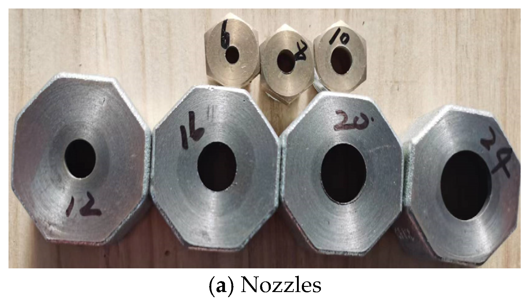
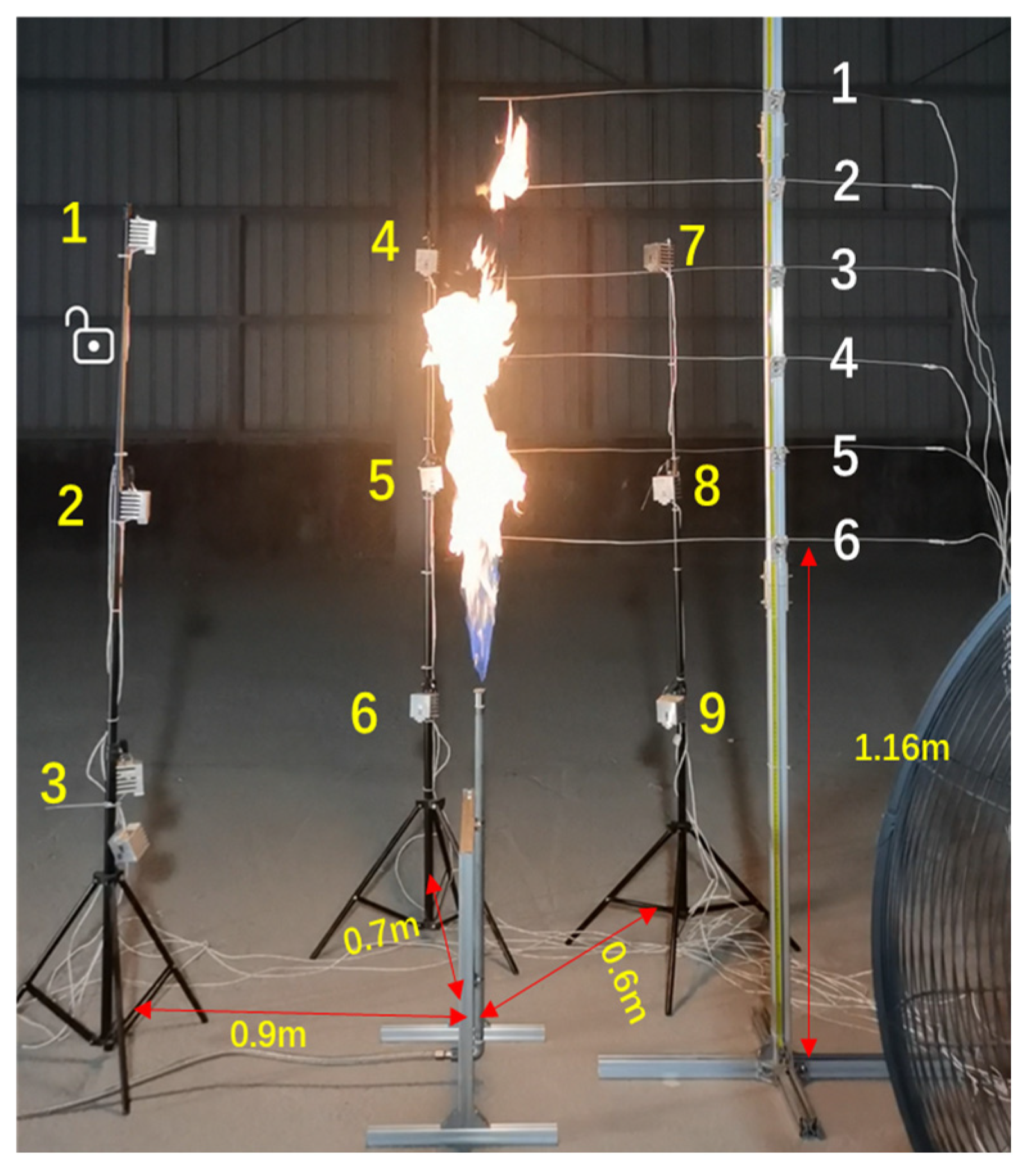
2.1. Experimental Setup

The experimental setup and measurement system for vertical methane jet flames are shown in Figure 1. The apparatus included a gas supply system, a float flowmeter, a thermometer, a series of nozzles, thermocouples for measuring the flame temperature, a radiometer for recording thermal radiation, a paperless recorder, and a camera. Pure methane gas was used for all experiments. The nozzle diameters used were 6 mm, 8 mm, 10 mm, 12 mm, 16 mm, 20 mm, and 24 mm, as shown in Figure 2a. The nozzles were connected to the gas pipe via threaded joints. For nozzles with diameters greater than 10 mm, a combustion chamber (with a diameter larger than that of the gas pipe) was installed above the vertical gas pipe [21], as shown in Figure 2b. This chamber was connected to a large-diameter nozzle to facilitate experiments involving larger nozzle diameters. When the nozzle diameter was less than 10 mm, the nozzle was positioned 830 mm above the ground. For nozzle diameters greater than 10 mm, the nozzle height was set to 1020 mm above the ground. The control variable method was applied to compare the thermal radiation and center flame temperature of jet flames at different flow rates under the same nozzle diameter (nozzle height above ground was consistent). In addition, the height of the spray chamber was considered when determining the flame height. The diameter of the gas pipe used in the experiments was 26.8 mm.
Nine TS-10C thermal radiation sensors, each with a measurement range of −200 to 200 kW/m2 and an accuracy of 3%, were evenly distributed across three thermal radiation measurement towers. These towers were positioned at horizontal distances of 600 mm, 700 mm, and 900 mm from the nozzle. On each tower, the sensors were mounted at heights of 620 mm, 1240 mm, and 1840 mm above ground level, establishing a spatially distributed system for capturing the thermal radiation from the jet flame, as shown in Figure 3. Additionally, 6 K-type thermocouples were installed above the nozzle, as shown in Figure 3, to measure the central temperature of the jet flame. The lowest thermocouple was positioned 1160 mm from the ground, with subsequent thermocouples placed at 200 mm intervals. These thermocouples had a measurement range of 0 to 1300 °C and an accuracy of 0.75%. A float flowmeter, with a range of 0.4 to 4 m3/h, was employed to measure the volumetric flow rate of the gas. A SIN-R6000C paperless China data recorder, with a measurement accuracy of 0.2% FS ± 1d, was used to log real-time data from both the thermal radiation sensors and the thermocouples. The temperature of the methane in the pipeline was monitored using a temperature sensor. A high-definition camera was utilized to capture the jet flame’s shape under various operating conditions and at different time intervals.

2.2. Data Processing

Images of the jet flame were extracted using video editing software. When the flame was stable enough to determine its height and width, as illustrated in Figure 4. The flame images were first converted into grayscale and then processed into binary images. Using the proportional relationship between the known length of the experimental apparatus and the flame height, the visible flame’s length and width were calculated. The flame width was defined as the maximum width of the flame. Thermal radiation and temperature data recorded by the paperless recorder were converted into actual thermal radiation and temperature values using signal channel coefficients. The time-dependent variations in the thermal radiation and temperature of the jet flame are shown in Figure 5a and Figure 5b, respectively. The average values of the thermal radiation and temperature during the stable data period were taken as the thermal radiation and temperature values.

3. Experiment Results and Analysis

Based on the methane vertical jet flame experimental setup, 44 sets of methane vertical jet flame experiments were conducted. A systematic analysis was performed to investigate the effects of the methane flow rate and nozzle diameter on the flame height, width, center temperature, and thermal radiation. The selected experimental parameters are presented in Table 1.

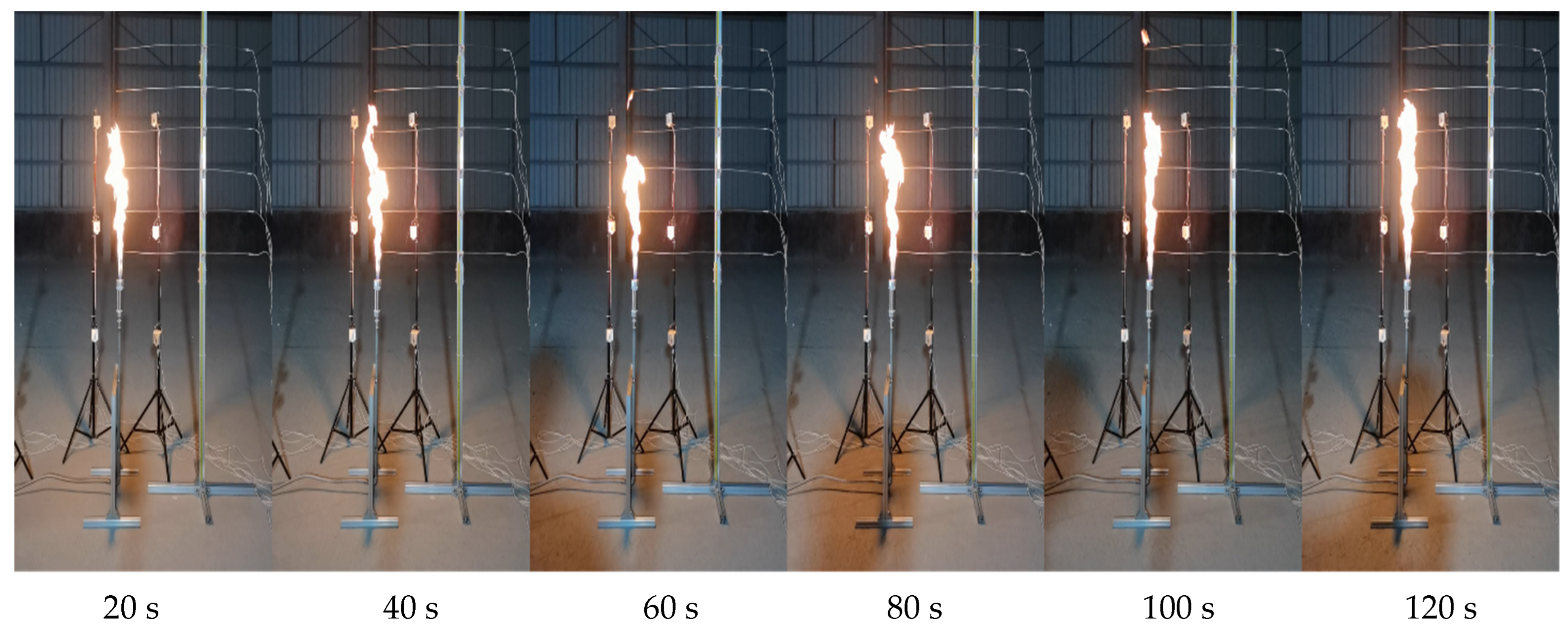
3.1. Effect of Methane Flow Rate and Nozzle Diameter on Jet Flame Height and Width

The effects of the methane flow rate and nozzle diameter on the height and width of the jet flame are shown in Figure 6, with the specific values of the methane flow rate and nozzle diameter provided in Table 1. The dimensionless flame height and width were defined as the ratios of the flame height to the nozzle height and the flame width to the nozzle diameter, respectively. As shown in Figure 6a,b, with a constant nozzle diameter, the flame height and width increased progressively as the methane flow rate increased. With a constant methane flow rate, an increase in the nozzle diameter led to a gradual increase in the flame height and width.

3.2. Effect of Methane Flow Rate and Nozzle Diameter on Jet Flame Temperature

The effects of the methane flow rate and nozzle diameter on the temperature along the central axis of the jet flame are shown in Figure 7. As shown in Figure 7, the temperature trends along the central axis of the jet flame were similar under different operating conditions. The temperature increased initially and then decreased with the distance from the nozzle along the central axis. However, the temperature distribution along the central axis varied with different conditions; the primary cause was the lift-off region at the base of the jet flame, where methane and oxygen did not fully mix, resulting in incomplete combustion and thus lower temperatures compared to the fully combusting region in the middle of the flame. Additionally, as the nozzle diameter and flow rate increased, both the flame height and lift-off height increased accordingly, altering the position of the high-temperature zone within the flame.
Figure 7a shows that at a constant distance from the nozzle outlet, the temperature along the central axis increased with higher flow rates. A significant temperature increase occurred as the flow rate was raised from 0.4 m3/h to 0.8 m3/h, while the temperature change was less pronounced when the flow rate increased from 2.4 m3/h to 2.8 m3/h. With the same flow rate, the temperature along the flame’s central axis increased initially and then decreased as the distance from the nozzle outlet increased.
Across all the tested flow conditions, the peak flame temperature was consistently observed at an axial position of 53 cm downstream from the nozzle exit, reaching a maximum recorded value of 1051 °C.
Figure 7b shows that the flame temperature fluctuated with an increasing flow rate, rather than rising continuously, when the distance along the central axis was ≤53 cm. For flow rates between 1.6 m3/h and 2.8 m3/h, the temperature 53 cm from the nozzle outlet remained consistent. A similar pattern was observed for flow rates between 0.8 m3/h and 1.2 m3/h, although there was a notable difference in the temperature compared to the higher flow rate conditions. When the distance along the central axis exceeded 53 cm, the flame temperature increased with the flow rate at the same location. At a constant flow rate, the flame temperature first rose and then fell with an increasing distance from the nozzle. With a nozzle diameter = 6 mm, the position of the maximum temperature along the central axis shifted. For flow rates between 1.6 m3/h and 2.4 m3/h, the maximum temperature was found at 53 cm, while at a flow rate of 2.8 m3/h, the maximum temperature occurred at 93 cm. The highest flame temperature measured was 896 °C.
From Figure 7c, it can be seen that with an increasing distance along the central axis, the flame temperature at the same location first rose and then fell. However, with a nozzle diameter = 8 mm, the position of the maximum temperature along the central axis shifted. With flow rates between 1.6 m3/h and 3.0 m3/h, the maximum temperature was observed at a distance of 73 cm from the nozzle outlet. When the distance along the central axis exceeded 73 cm, the temperature at the same location increased with the flow rate. The highest recorded flame temperature was 889 °C.
In Figure 7d, it can be seen that a spray chamber was added, with the thermocouple closer to the nozzle. As shown in Figure 7d, the flame temperature along the central axis of the jet flame initially increased and then decreased as the distance from the nozzle outlet increased. When the distance along the central axis was less than 34 cm, the flame temperature at the same location decreased as the flow rate increased. In contrast, when the distance exceeded 54 cm, the trend was reversed. At distances of 34 cm and 54 cm from the nozzle, the flame temperature remained relatively constant as the flow rate increased. At a methane flow rate of between 2 m3/h and 2.2 m3/h, the maximum flame temperature was observed at a distance of 34 cm along the central axis. When the flow rate increased to between 2.4 m3/h and 3.2 m3/h, the maximum flame temperature occurred at a distance of 74 cm. The highest recorded flame temperature under these conditions was 898 °C.
Figure 7e indicates an initial increase followed by a subsequent decrease in the axial flame temperature with an increasing downstream distance from the nozzle. Notably, the position of the peak temperature differed from that observed in the 12 mm nozzle condition. For methane flow rates of 2.0–2.2 m3/h, 2.4–2.6 m3/h, and 2.8–3.2 m3/h, the maximum flame temperatures occurred at axial positions of 34 cm, 54 cm, and 74 cm, respectively, with the highest recorded temperature reaching 818 °C.
Figure 7f,g reveal distinct temperature distribution patterns under different flow conditions. At an axial position of 13 cm from the nozzle exit, the flame temperature exhibited an inverse relationship with the flow rate. However, beyond 54 cm along the flame axis, the temperature profile demonstrated flow-rate-dependent fluctuations rather than the monotonic increase observed in other configurations. The peak temperatures, recorded in Figure 7f,g, reached 775 °C and 737 °C, respectively.

3.3. The Effect of the Methane Flow Rate and Nozzle Diameter on the Thermal Radiation of Jet Flames

Figure 8 illustrates the effects of the methane flow rate and nozzle diameter on the thermal radiation characteristics of the jet flame. The experimental setup adopted nine radiometers distributed across three vertical arrays, creating a three-dimensional measurement system. However, due to an operational failure of radiometer 6, only data from the remaining eight radiometers are reported. As shown in Figure 8a–g, the measured radiative heat flux exhibited a positive correlation with an increasing methane flow rate. Notably, radiometers positioned in the lower sections of the arrays (e.g., radiometers 3 and 9) recorded comparatively lower radiative fluxes with a more gradual rate of increase. In contrast, radiometers located in the middle and upper sections (radiometers 1–2, 4–5, and 7–8) showed more pronounced increases in the radiative flux. These spatial variations in the thermal radiation distribution could be explained by two primary factors: the presence of a flame lift-off region near the base, which generated significantly lower radiative emissions compared to the more fully developed middle and upper flame regions, and the geometric effect of wider viewing angles for the lower-positioned radiometers, which reduced the measured radiant flux density. Furthermore, increasing either the flow rate or nozzle diameter resulted in greater flame heights and an upward shift in the position of the peak radiation.
Figure 8a demonstrates a distinct vertical stratification in the measured radiation, with the highest values observed at medium heights, intermediate values at the top, and the lowest values at the base of the measurement arrays. Furthermore, at equivalent elevation levels, the recorded flux varied inversely with the radial distance from the flame center. Specifically, radiometer 8 (closest to the flame axis) registered the highest flux, followed sequentially by radiometers 5 and 2 at progressively greater radial offsets. This trend was similarly evident in the comparison between radiometers 7, 4, and 1. An exception to this pattern occurred at the base level, where radiometer 9 recorded lower values than radiometer 3, likely attributable to differences in the view factor geometry. Notably, the absolute maximum radiation was consistently recorded by radiometer 8 across all experimental conditions.
In Figure 8b, it can be seen that the trend of the thermal radiation values across the radiometers was similar to that in Figure 8a. However, with an increase in the flow rate, the values recorded by the radiometers in the middle of the radiation tree gradually became smaller than those at the top. For example, radiometers 7 and 1 at the top progressively recorded higher values than radiometers 8 and 2 in the middle. Moreover, as the flow rate increased, radiometer 7 consistently recorded higher values than the other radiometers.
The trend observed in Figure 8c is consistent with that in Figure 8b, though with a notable distinction: as the flow rate increased, the thermal radiation measured by radiometer 4 (top position) progressively exceeded that of radiometer 5 (middle position), approaching the peak value recorded by radiometer 8. Nevertheless, radiometer 7 consistently registered the highest radiation across all conditions.
As is evident from Figure 8d, radiometer 7 demonstrated markedly elevated radiation values compared to the other sensors, while radiometer 4 exhibited the second-highest measurements. Radiometers 5 and 8 displayed comparable radiation intensities. Furthermore, the data revealed a consistent vertical stratification, with the uppermost radiometers registering higher radiation than their mid-level counterparts. The radiation distribution patterns in Figure 8e–g exhibit qualitatively similar behavior to those in Figure 8d, and a discussion of them is thus omitted for brevity.
Figure 8e clearly shows that radiometer 7 measured substantially greater radiation than all other sensors, with radiometer 4 recording the second-highest intensity. Radiometers 5 and 8 exhibited comparable radiation levels. The data further revealed a consistent vertical gradient, with the uppermost sensors detecting significantly stronger radiation than those at a medium height. The observed flow rate dependence of the radiation distribution in Figure 8e–g follows the same characteristic pattern as that shown in Figure 8d, and thus its discussion is not repeated here.

4. Conclusions

(1)
As the distance along the jet flame’s central axis from the nozzle increased, the temperature initially rose and then decreased. With an increase in the nozzle diameter, the position of the highest temperature along the axis fluctuated. For nozzle diameters below 16 mm, the post-peak axial temperatures displayed a positive correlation with the flow rate. In contrast, for diameters exceeding 12 mm at an axial distance of 130 mm, the local flame temperature was inversely correlated with the flow rate.
(2)
Both an increasing gas flow rate or nozzle diameter resulted in an upward shift in the peak thermal radiation position along the flame height. The radiation measurements revealed a distinct vertical stratification, with the upper flame region exhibiting significantly higher radiation intensities compared to the middle section. Meanwhile, the base region maintained relatively stable radiation levels and consistently recorded the lowest values among all the measured positions.
(3)
As the flow rate and nozzle diameter increased, the height and width of the jet flame increased. The flame’s lift-off height and shape were key factors influencing the central temperature and the distribution of the jet fire’s thermal radiation.

Author Contributions

Methodology, B.S.; Resources, C.H.; Data curation, J.Y.; Writing—original draft, Y.P.; Writing—review & editing, Y.P.; Visualization, G.F.; Supervision, W.C.; Project administration, J.Z. All authors have read and agreed to the published version of the manuscript.

Funding

This work was supported by the National Natural Science Foundation of China [5228810005] and the Youth Fund of the CNPC Engineering Technology R&D Company Limited [CPETQ202405].

Data Availability Statement

The original contributions presented in this study are included in the article. Further inquiries data can be directed to the corresponding author.

Conflicts of Interest

Authors Yudan Peng, Jing Yu, Weifeng Chen, Chen Hao, Jiawei Zhang were employed by the company CNPC Engineering Technology R&D Company Limited. The remaining authors declare that the research was conducted in the absence of any commercial or financial relationships that could be construed as a potential conflict of interest. The company had no role in the design of the study; in the collection, analyses, or interpretation of data; in the writing of the manuscript, or in the decision to publish the results.

References

  1. Engineering Technology and Marketing Department of China National Petroleum Corporation. Compilation of Blowout Accident Cases of China National Petroleum Corporation; Petroleum Industry Press: Beijing, China, 2006. [Google Scholar]
  2. Yang, J.; Xu, N.; Zhou, X. Analysis on influence dimension of jet flame hazard in natural gas pipeline. Chem. Eng. Oil Gas 2022, 51, 121–126. [Google Scholar]
  3. Zeng, C.; Shan, Y.G. Modelling of the evolution of jet fire caused by continuous discharge of propane from a LPG Tank. J. Univ. Shanghai Sci. Technol. 2015, 37, 473–478. [Google Scholar]
  4. Tian, H. The lifting of the ban on deepwater oil and gas exploration in the United States has led to a surge in exploration and development in the Gulf of Mexico. Int. Pet. Econ. 2012, 1, 3. [Google Scholar]
  5. Yi, M. Analysis of the “6.10” Leakage and Explosion Accident in the Qinglong Section of the PetroChina China Myanmar Natural Gas Pipeline in Qianxinan Prefecture. Jilin Labour Prot. 2021, 9, 2. [Google Scholar]
  6. Li, Y. Research on Heat Radiation in Gas Jet Fire. China Saf. Sci. J. 2011, 21, 68–71. [Google Scholar]
  7. Chen, G.; Zhou, Z.; Huang, T. A validation study of the fire dynamics simulator Fluent for modeling large-scale impinging gas jet fires. Nat. Gas Ind. 2014, 34, 134–140. [Google Scholar]
  8. Mashhadimoslem, H.; Ghaemi, A.; Behroozi, A.H.; Palacios, A. A New simplified calculation model of geometric thermal features of a vertical propane jet fire based on experimental and computational studies. Process Saf. Environ. Prot. 2020, 135, 301–314. [Google Scholar] [CrossRef]
  9. Mashhadimoslem, H.; Ghaemi, A.; Palacios, A.; Behroozi, A.H. A new method for comparison thermal radiation on large-scale hydrogen and propane jet fires based on experimental and computational studies. Fuel 2020, 282, 118864. [Google Scholar] [CrossRef]
  10. Palacios, A.; Rengel, B. Flame shapes and thermal flux of vertical hydrocarbon flames. Fuel 2020, 276, 118046. [Google Scholar] [CrossRef]
  11. Palacios, A.; Muñoz, M.; Darbra, R.M.; Casal, J. Thermal radiation from vertical jet fires. Fire Saf. J. 2012, 51, 93–101. [Google Scholar] [CrossRef]
  12. Gore, J.P.; Faeth, G.M.; Evans, D.; Pfenning, D.B. Structure and radiation properties of large-scale natural gas/air diffusion flames. Fire Mater. 1986, 10, 161–169. [Google Scholar] [CrossRef]
  13. Lowesmith, B.J.; Hankinson, G. Large scale high pressure jet fires involving natural gas and natural gas/hydrogen mixtures. Process Saf. Environ. Prot. 2012, 90, 108–120. [Google Scholar] [CrossRef]
  14. Chen, D.; Kou, J.; Yang, R.; Zhu, J.; Zhang, Y.; Pan, J. Experiment on combustion characteristics of outdoor high pressure natural gas jet fire. Oil Gas Storage Transp. 2023, 42, 113–120. [Google Scholar]
  15. Zhou, B.; Liang, S.; Wang, P. Comparative analysis on influence ranges and models of thermal radiation by jet fire in well blowout. J. Saf. Sci. Technol. 2022, 18, 139–144. [Google Scholar]
  16. Zhou, M.; Zhou, K.; Wang, C.; Huang, M.; Wang, Y.; Jiang, J. Flame behavior of horizontal propane jet fire in a pit. CIESC J. 2022, 73, 960–971. [Google Scholar]
  17. Li, Y.; Liu, P.; Geng, X.; Liu, C.W.; Zhang, Y.X.; Wang, J.G. Study on Combustion Characteristics of Methane Horizontal Jet Fire with Obstacles. Oil-Gas Field Surf. Eng. 2019, 38, 7. [Google Scholar]
  18. Wu, Y.; Zhou, K.; Huang, M. Flame behavior of jet fire confined by the tank wall. CIESC J. 2021, 72, 2896–2904. [Google Scholar]
  19. Hajidavalloo, E.; Omidian, P. Modeling and simulation of flow field around a blowout well. SPE J. 2012, 17, 212–218. [Google Scholar] [CrossRef]
  20. Hajidavalloo, E.; Dehkohneh, S.A. Effects of perforated flow tube on the flow field of a blowout well. SPE J. 2016, 21, 1470–1476. [Google Scholar] [CrossRef]
  21. Zhou, Z. Study on Hazard Characteristics of Jet Fire and Domino Effect Pre-Control in Natural Gas Transmission Pipelines. Ph.D. Thesis, South China University of Technology, Guangzhou, China, 2019. [Google Scholar]
Figure 1. Methane jet flame experimental device.
Processes 13 01207 g001
Figure 2. Nozzles and a spray chamber.
Processes 13 01207 g002aProcesses 13 01207 g002b
Figure 3. Distribution of thermal radiometers and thermocouples.
Processes 13 01207 g003
Figure 4. Changes in jet flame morphology between different times.
Processes 13 01207 g004
Figure 5. Temperature and thermal radiation values of jet flames.
Processes 13 01207 g005
Figure 6. The effect of the methane flow rate and nozzle diameter on the jet flame’s height and width.
Processes 13 01207 g006
Figure 7. Effect of methane flow rate and nozzle diameter on jet flame temperature.
Processes 13 01207 g007
Figure 8. Effects of methane flow rate and nozzle diameter on thermal radiation of jet flames.
Processes 13 01207 g008aProcesses 13 01207 g008b
Table 1. Experimental operating condition parameters.
Nozzle Diameter/mmGas Flow Rate/m3·h−1
60.4, 0.8, 1.2, 1.6, 2.0, 2.4, 2.8
80.8, 1.2, 1.6, 2.0, 2.4, 2.8
101.6, 2.0, 2.4, 2.8, 3.0
122.0, 2.2, 2.4, 2.6, 2.8, 3.2
162.0, 2.2, 2.4, 2.6, 2.8, 3.2
202.0, 2.2, 2.4, 2.6, 2.8, 3.2
242.0, 2.2, 2.4, 2.6, 2.8, 3.2
Disclaimer/Publisher’s Note: The statements, opinions and data contained in all publications are solely those of the individual author(s) and contributor(s) and not of MDPI and/or the editor(s). MDPI and/or the editor(s) disclaim responsibility for any injury to people or property resulting from any ideas, methods, instructions or products referred to in the content.

