Article

Stability Analysis of Borehole Walls in Shale Formations of the Huazhuang Block

1
Sinopec Petroleum Engineering Technology Research Institute Co., Ltd., Beijing 102206, China
2
State Key Laboratory of Shale Oil and Gas Enrichment Mechanisms and Effective Development, Beijing 102206, China
3
School of Petroleum Engineering, Yangtze University, Wuhan 430100, China
*
Author to whom correspondence should be addressed.
Processes 2025, 13(4), 1151; https://doi.org/10.3390/pr13041151
Submission received: 11 March 2025 / Revised: 7 April 2025 / Accepted: 9 April 2025 / Published: 10 April 2025
(This article belongs to the Section Energy Systems)

Abstract

:
The Huazhuang block, located on the northern slope of the Gaoyou Depression in the Subei Basin of the Jiangsu Oilfield, exhibits complex stratigraphic geomechanical characteristics. During drilling, wellbore instability-related issues, such as obstruction, sticking, pump pressure buildup, bit pressure buildup, and overflow due to abnormally high pressure, prolong the drilling cycle and significantly hinder the safe and efficient development of shale oil. In order to determine the appropriate drilling fluid density and ensure safe and efficient drilling in this block, a comprehensive wellbore profile, incorporating rock mechanical parameters, in-situ stress, and predictions of pore pressure, collapse pressure, lost circulation pressure, and fracture pressure, was established based on laboratory tests and well logging data. This study reveals the mechanisms of wellbore collapse and fluid loss in the Huazhuang block. The results indicate that the second and fourth members of the Funing Formation in the Huazhuang block have a relatively weak and unconsolidated structure with a high content of water-sensitive minerals, leading to significant hydration risks when using water-based drilling fluids. As depth increases, compressive strength, elastic modulus, and cohesion show an increasing trend, while the internal friction angle and Poisson’s ratio gradually decrease. Additionally, in-situ stress increases significantly, meeting the condition of σ V > σ H > σ h . Above 3300 m, the equivalent density of formation pore pressure is below 1.20 g/cm3, Whereas below 3300 m, there is significant overpressure, with a maximum equivalent pore pressure density reaching 1.45 g/cm3. The deeper the formation, the narrower the safe density window, making wellbore collapse more likely. To prevent wellbore instability, both the sealing capability and density of the drilling fluid should be considered. Enhancing the sealing performance of the drilling fluid and selecting an appropriate drilling fluid density can help improve wellbore stability. The established rock mechanical parameters and four-pressure prediction profile for the Huazhuang block provide a scientific basis for optimizing wellbore structure design and selecting key engineering parameters.

1. Introduction

With the continuous advancement of unconventional oil and gas exploration technologies and the increasing exploration depth, the exploration and development of shale oil and gas resources have become a key focus of global research, as well as a priority in China’s “14th Five-Year Plan” key scientific and technological initiatives [1]. The Subei Basin, which is located to the west of the Lusu Uplift, south of the Tongyang Uplift, and extends eastward into the Yellow Sea, is part of the onshore section of the Subei-South Yellow Sea Basin [2]. This block is rich in shale oil resources, but due to its complex geological and mechanical characteristics, drilling is often hindered by issues such as borehole wall collapse instability, wellbore obstruction, pipe sticking, pump pressure buildup, stuck pipe, and overflow induced by abnormal high pressure. These issues extend the drilling cycle and severely restrict the safe and efficient development of shale oil. Therefore, effectively evaluating the borehole wall stability of shale reservoirs and proposing effective technical measures for borehole stability are of significant importance for safe and efficient drilling.
For many years, numerous experts and scholars have conducted in-depth research on the issue of borehole wall instability encountered during drilling. Fan Yu et al. [3] studied the fracture fluid loss, pressure distribution within fractures, and the stress distribution around the wellbore for the Upper Shaxi Miao Formation in the ultra-deep wells of the Shuangyushi Block in the western Sichuan Basin. They established a collapse pressure calculation model for fractured formations, considering the effects of wellbore size. They analyzed the wellbore instability mechanisms of the Shaxi Miao Formation and proposed technical countermeasures to prevent borehole wall instability. Gao Shuyang et al. [4] addressed the technical challenges faced the drilling of the Subei continental shale oil reservoirs, such as frequent stuck pipes and high drilling difficulty. They conducted a geological characteristic and laboratory experimental evaluation. The results showed that the mud shale layers of the Funing Formation Member 2 had strong structural coherence, and the drilling fluid filtrate invaded the formation’s micro-fractures under differential pressure and suction, leading to the extension of numerous micro-fractures and a significant deterioration of the rock’s mechanical integrity, which caused borehole wall instability. Based on these findings, targeted wellbore stability control techniques, such as enhanced inhibition, high-efficiency sealing, and wetting reversal, were developed, achieving wellbore stability by preventing external water invasion and controlling internal swelling. Zhang Mingming et al. [5] investigated the collapse pressure and instability region variations of fractured formation borehole walls. Combining the modified Mohr-Coulomb (MC) strength criterion and the fracture surface strength criterion under triaxial stress, they established a predictive model for collapse pressure and instability regions in fractured formations. Their study revealed that, under triaxial stress, borehole collapse is primarily controlled by a specific fracture set. By adjusting the wellbore axial orientation relative to this fracture surface, the severity of wellbore instability can be mitigated or controlled. Wang Yuepeng et al. [6] based on in-situ stress, rock mechanics, and other laboratory physical experiments, combined with field engineering parameters and loss information, established a full-well geomechanical parameter profile and four-pressure profile model for deep wells in the western fault zone. They evaluated the distribution of rock mechanical parameters in different lithologies and revealed the instability mechanisms, such as borehole collapse and fluid loss, in the western fault zone deep wells. The results showed that the sand-shale layers above the Yanghugang Formation have relatively low strength (20–100 MPa), while the limestone from the Rushzhong Formation to the Zhuangshan Formation exhibits higher strength (>100 MPa). The large horizontal principal stress difference, fracture zones, and coal seams were the main causes of borehole instability. Fan Xiangyu et al. [7] systematically summarized and analyzed the wellbore instability mechanisms in ultra-deep formations from both geological and engineering perspectives. They further analyzed the rock physics and mechanics experiments, constitutive equations, in-situ stress measurements, and formation pressure prediction techniques for evaluating geomechanical parameters in ultra-deep formations. They discussed the progress in the evaluation theory and control technologies for borehole stability in ultra-deep formations and proposed suggestions for advancing drilling technologies in ultra-deep formations. Luo Ming et al. [8] conducted uniaxial and triaxial mechanical experiments on shale from the Longmaxi Formation in southern Sichuan, after immersion in various drilling fluids. They analyzed the changes in mechanical properties and failure modes and discussed the mechanisms of borehole wall instability. The results indicated that the mechanical properties of shale exhibited obvious anisotropy due to bedding, with a confining pressure effect. Oil-based drilling fluids enhanced anisotropy by lubricating the bedding planes, causing shear failure along these planes, while water-based drilling fluids caused hydration damage, leading to micro-crack propagation and connecting bedding planes, which reduced anisotropy and made compound failure more likely. The destruction was controlled by both the matrix and bedding planes, making the wellbore more prone to instability. The hydration of clay minerals and capillary effects in pore cracks were identified as the fundamental causes of borehole wall instability in shale formations. Based on the above research results, conventional wellbore stability analysis is mostly conducted using rock mechanics parameters combined with logging data, without incorporating rock mineral composition analysis and microscopic characteristics analysis. As a result, there is a lack of systematic understanding of the mechanism of wellbore instability.
Based on this, this paper analyzes the wellbore instability of the target shale formation in the Huazhuang Block, determines the causes of wellbore instability based on the results of laboratory tests and evaluations, explores the collapse instability mechanisms of shale formations, and proposes wellbore stability control techniques. The aim is to provide insights and references for further research on the wellbore instability mechanisms of continental shale formations and the development of suitable drilling fluid systems. Ultimately, the study seeks to recommend a safe mud weight window and safe production processes for the block that can prevent wellbore instability.

2. Rock Fabric Characteristic Testing and Mechanical Characteristic Experiments

The Huazhuang Block in the northern slope of the Gaoyou Depression, Subei Basin, Jiangsu Oilfield, exhibits a complete development of structural strata, including the Quaternary Dongtai Formation (Qd), the Neogene Yancheng Formation (Ny), and the Paleogene Sanduo Formation (E2s), Dainan Formation (E2d), and Funing Formation (E1f) from top to bottom [9,10]. The primary target strata are located in the Funing Formation (E1f4, E1f2), with the main lithologies being gray-black mudstone and siltstone [11]. By analyzing previous drilling data, it is evident that there is significant abnormal high pressure between the E1f3 and E1f2 intervals, with the maximum pressure equivalent reaching 1.42 g/cm3. The primary drilling fluid system used is a composite metal-ion polymer-sulfonate drilling fluid, with the drilling fluid density for the Funing Formation ranging from 1.22 to 1.55 g/cm3. The shallow Yancheng Formation and the primary target strata in the Funing Formation exhibit noticeable wellbore enlargement. This shale reservoir is mainly an interlayered type with well-developed bedding and microfractures. The invasion of drilling fluid filtrate causes hydration and swelling of the shale surface, leading to the cracking of microfractures, weakening the interlayer forces of clay minerals, and reducing the strength, which makes the borehole more prone to collapse and instability. The primary technical challenges in this block include the periodic collapse of the shale layers and the accurate prediction of the abnormal high pressure in the Funing Formation. Therefore, a representative well, Huaye 7, was selected, and core samples from the Funing Formation were taken for analysis. Using mineral composition analysis, scanning electron microscopy (SEM), rock mechanics testing, and field data, the instability causes of the mud shale wellbore in the Funing Formation of the Gaoyou Depression were explored.

2.1. Mineral Composition Analysis

The mineral composition of the core samples taken from the Funing Formation of well Huaye 7 was analyzed using X-ray diffraction (XRD). The full mineral analysis and the relative content analysis of various minerals were performed, and the results are shown in Table 1 and Table 2.
Based on the data from Table 1 and Table 2, it can be concluded that the clay mineral content in the Funing Formation, E1f2 and E1f4 layers in the Huazhuang Block ranges between 40% and 60%. The clay mineral content is relatively high, with illite and illite-smectite mixed layers being the dominant minerals, followed by chlorite. The proportion of illite-smectite mixed layers in the clay minerals ranges from 17% to 20%. Additionally, the high content of water-sensitive minerals increases the risk of hydration during drilling with water-based drilling fluids.

2.2. Core Microscopic Characteristics Analysis

The microscopic characteristics of selected rock samples from the Funing Formation of the Huazhuang Block (Huaye 7 well) were examined under a polarized light microscope, with the identification results shown in Figure 1. Thin section analysis showed that the E1f4 reservoir of the Funing Formation in the Huazhuang Block primarily consists of laminated shale or silty shale, characterized by horizontally interbedded silt bands, clay bands, and organic-rich peat layers. Localized quartz aggregates and quartz-filled silt pores are also observed. The E1f2 member of the Funing Formation is primarily composed of mudstone, exhibiting a clay-dominated structure and a microscopic felted texture. It contains abundant peat material and exhibits indistinct bedding. Biological remains are predominantly ostracods, with occasional bivalve fragments. Calcite-filled fractures are also present. The Huazhuang Block has a high clay mineral content, primarily composed of illite and illite-smectite mixed layers, with the latter being more abundant. These minerals readily absorb water and swell, compromising the core’s internal structure. This process leads to exfoliation, block detachment, and ultimately, shale wellbore collapse. The impact of drilling fluids should be accounted for in the wellbore stability analysis of the target block. Scanning electron microscopy (SEM) was also employed to examine the microscopic characteristics of core samples from the Huazhuang Block (Huaye 7 well), with the results shown in Figure 1. SEM analysis indicated that the overall rock structure of the E1f2 and E1f4 members of the Funing Formation is relatively porous and loosely compacted. Clay mineral aggregates exhibit a fibrous morphology and a flaky, directional arrangement, interspersed with quartz particles, argillaceous silicates, and spherical pyrite crystal aggregates. In the E1f4 member, clay mineral aggregates are coated with carbonaceous material.

2.3. Rock Mechanics Characteristics Analysis

The rock cores used in this laboratory experiment were obtained from the Huazhuang Huaye 7 well. According to the testing methods and standards of the International Society for Rock Mechanics (ISRM) [12], a 25 mm cylindrical sample was drilled from large rock cores collected at the site using a diamond-hard alloy coring bit. The cores were then cut into cylindrical specimens with a diameter of 25 mm and a length of approximately 50 mm using wire cutting methods. The parallelism deviation at both ends of the specimen should not exceed 0.1 mm, and the diameter deviation should not exceed 0.2 mm.

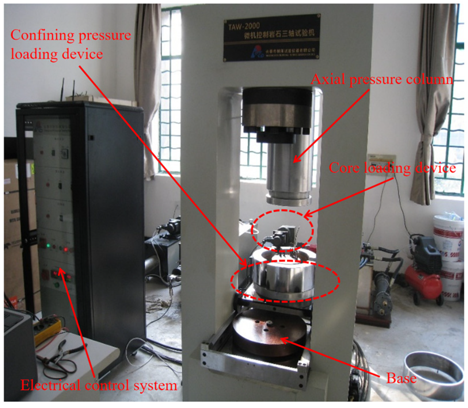
2.4. Compressive Strength Experiment

The rock strength experiments were conducted using the TAW-2000 microcomputer-controlled electro-hydraulic servo rock triaxial testing machine produced by Changchun Chaoyang Experimental Instrument Company, as shown in Figure 2. The complete setup consists of five main components: a high-pressure triaxial chamber, confining pressure pressurization system, axial pressurization system, temperature control system, and a data acquisition control system. A total of eight rock samples from the Funing Formation, E1f2, in the Huazhuang Block were tested in the laboratory, as shown in Figure 3. The experimental results are summarized in Table 3.
Based on the data from Table 3 and Figure 3, it can be observed that as confining pressure increases, the rock’s compressive strength and elastic modulus gradually increase, while the Poisson’s ratio decreases. This indicates that as the drilling depth increases, the rock’s ability to resist external forces improves. Therefore, when analyzing wellbore stability, it is necessary to further consider the formation conditions and their impact on the rock’s mechanical properties. After the rock compression tests, the overall degree of fragmentation of the rock samples remains low, and the original cylindrical shape is mostly maintained, with occasional through cracks occurring.

3. Prediction Profile Construction and Wellbore Stability Analysis

3.1. Rock Mechanical Parameter Prediction Profile

Based on the indoor strength testing results, the relationship between dynamic Poisson’s ratio and dynamic elastic modulus is calculated using the longitudinal and transverse wave velocities, as shown in the following Equation (1) [13]:
E d = ρ × V s 2 × ( 3 V p 2 4 V s 2 ) V p 2 V s 2
u d = V p 2 2 V s 2 2 ( V p 2 V s 2 )
In the formula: E d is the dynamic elastic modulus (MPa); u d is the dynamic Poisson’s ratio, dimensionless; ρ is the formation density; Vp is the P-wave velocity; Vs is the S-wave velocity.
It is difficult to establish a vertical strength prediction profile for each well based solely on limited core strength tests. In this study, a logging data-based strength prediction model was established using logging data and core strength tests, as shown in Equation (3) [14].
P u c s = K 1 ( 1 2 μ d ) 1 + μ d 1 μ d 2 ρ 2 V P 4 ( 1 + 0.78 V c l )
C = K 2 ( 1 2 μ d ) 1 + μ d 1 μ d 2 ρ 2 V P 4 ( 1 + 0.78 V c l )
ϕ = K 3 + K 4 C
In the formula: P u c s is the uniaxial compressive strength of the rock, MPa; μ d is the dynamic Poisson’s ratio; V c l is the clay content; C is the cohesion, MPa; ϕ is the internal friction angle, °; and K 1 , K 2 , K 3 , K 4 are empirical coefficients.
Using the measured uniaxial compressive strength (Table 1) and corresponding logging data at each depth, the empirical coefficient for uniaxial compressive strength in the Huazhuang block was determined to be 0.0208. Based on indoor measurement data, the cohesion coefficient for the Huazhuang block was calibrated to 0.0260.The rock mechanics parameter calculation model, derived from indoor experimental results, was applied in combination with logging data such as sonic travel time to determine the rock mechanics parameters for the Huazhuang block. These parameters include uniaxial compressive strength (Pucs), tensile strength (TS), cohesion (CH), internal friction angle (IFA), elastic modulus (E), and Poisson’s ratio (PR). The depth profiles of these parameters are presented in Figure 4.
Figure 4 shows the rock mechanics parameter profiles for the Huazhuang block, illustrating how parameters such as uniaxial compressive strength (Pucs), tensile strength (TS), cohesion (CH), internal friction angle (IFA), elastic modulus (E), and Poisson’s ratio (PR) change with well depth.
From Figure 4, it can be seen that with the increase in well depth, the compressive strength, elastic modulus, and cohesion tend to increase gradually, while the internal friction angle and Poisson’s ratio tend to decrease. The fluctuation of rock mechanics parameters is significant, both within the same layer and between different layers.
The compressive strength of the Yancheng Formation is the lowest, with a range of 2.4 ~ 192 MPa. The compressive strength of the Santuo Formation ranges from 3.5 ~ 245 MPa, and the compressive strength of the Dainan Formation ranges from 6.3 ~ 496.1 MPa. The compressive strength of the Funing Formation is the highest, ranging from 11.1 ~ 692.8 MPa. Below the Dainan Formation, the compressive strength of the Funing Formation increases sharply with well depth.
Tensile strength below the Dainan Formation is higher, with an average value greater than 5 MPa, while the tensile strength above it has an average value less than 2 MPa. The average cohesion below the Dainan Formation is 38 MPa, while above it, the average cohesion is 22 MPa. According to the Mohr-Coulomb strength failure criterion, lower cohesion results in smaller shear stresses required to cause rock failure. Therefore, the risk of wall collapse due to shear failure is higher. Additionally, the complex lithology and well-developed fractures in the Huazhuang block may increase the collapse pressure and reduce the loss pressure, which could adversely affect wellbore stability.

3.2. Prediction of In-Situ Stress Profile

To maintain wellbore stability and ensure the safety and quality of drilling operations, it is essential to determine the appropriate mud density during the drilling process. Wellbore stability issues include wellbore collapse or tightness (caused by shear failure or plastic flow of rocks) and formation rupture or fracturing (due to tensile failure of rocks). Quantitative research focuses on determining the mud density range that ensures the formation does not collapse (or shrink) and does not fracture or leak, providing the basis for wellbore structure design and the determination of appropriate mud density. In light of this, it is necessary to determine the appropriate mud density window for the Huazhuang block to prevent wellbore collapse and fracture [15,16].
For different well depths and strata with varying mechanical properties, the in-situ stress values will be different. For the Huazhuang block, the in-situ stress can be calculated using the following model as shown in Equation (6) [17]:
σ H = μ d 1 μ d + ω 1 σ V α P p + α P p σ h = μ d 1 μ d + ω 2 σ V α P p + α P p
In the equation, ω 1 , ω 2 represent the tectonic stress coefficient and α represent the effective stress coefficient; P p represents the pore pressure of the formation; σ H and σ h are the maximum and minimum horizontal in-situ stresses, respectively, while σ V is the overburden pressure.
In the calculation of in-situ stress, the determination of the tectonic stress coefficient, ω 1 , ω 2 , is crucial. The values of ω 1 and ω 2 are determined by performing a Kaiser effect test at specific depths, and these values are then substituted into the in-situ stress calculation model (Equation (6)) to obtain the results. Based on the field leakage test data collected from the Huazhuang block and combined with the rock mechanics parameters and stratified in-situ stress model, the tectonic stress coefficient for the Huazhuang block has been reverse-calculated as follows: ω 1 = 0.6657 ; ω 2 = 0.3955 .
By substituting the tectonic stress coefficient into Equation (6) and combining the well logging data, the vertical in-situ stress profile for the Huazhuang block Huaye 7 well is obtained, as shown in Figure 5. From the figure, it can be seen that as the well depth increases, the in-situ stress gradually increases, and the following relation is satisfied: σ V > σ H > σ h .

3.3. Four-Pressure Prediction Profile

Using field data such as well loss and overflow as calibration points, combined with on-site engineering logging data, theoretical prediction models and normal trend line models can be established for pore pressure, collapse pressure, loss pressure, and fracture pressure in different lithologic formations [18,19]. The calculation models for the pore pressure, collapse pressure, leakage pressure, and fracture pressure in the Huazhuang block are shown in Equations (7)–(10) [20,21,22,23].
P p = P o p ( P o p ρ ) ( t n / t ) n
P C = η 3 σ H σ h 2 C K + α P p ( K 2 1 ) K 2 + η
P L = P p + α P f P p
P f = 2 μ d 1 μ d Q σ V α P p + α P p + S t
In the formulas, P p represents the formation pore pressure, M P a ; P o p represents the overburden rock pressure equivalent density at a depth of H, g / c m 3 ; ρ represents the formation water density at a depth of H, g / c m 3 ; t n represents the sonic time difference at the depth H under normal pressure conditions, in seconds; t represents the measured sonic time difference at the depth H, in seconds; n represents the Eaton exponent. P C represents the formation collapse pressure, M P a ; η represents the nonlinear correction coefficient, generally taken as 0.95; K is the coefficient related to the internal friction angle, K = cot ( 45 ° ϕ 2 ) ; P L represents the formation leakage pressure. Q = 3 ω 1 ω 2 represents the tectonic stress coefficient; σ V represents the overburden pressure, M P a ; P p represents the formation pore pressure, M P a ; S t represents the formation tensile strength, M P a ; μ d represents the Poisson’s ratio; α represents the effective stress coefficient.
Taking Well Huaye 7 as an example, the pressure profiles—including pore pressure, collapse pressure, leakage pressure, and fracture pressure—were obtained for the entire well section from 500 m to 4300 m in the Huazhuang block, as shown in Figure 6. The figure shows that the collapse pressure is relatively high in most formations encountered by Well Huaye 7. During actual drilling, the leakage zones are mostly associated with fractured formations, where the leakage pressure is slightly higher than the pore pressure. Even with low-density drilling fluid, continuous leakage persists. Due to the extensive fracturing and significant lithological variations in the drilled formations, the collapse pressure is high and fluctuates greatly, while the leakage pressure remains low. As a result, both severe borehole collapse and fluid leakage occur during drilling. In some formations, such as the Funing Formation, the leakage pressure and collapse pressure are close. This makes it difficult to simultaneously prevent both collapse and leakage, posing significant challenges to normal drilling operations.

4. Analysis of Borehole Instability Causes and Countermeasures Recommendations

4.1. Analysis of Drilling Complexities

Based on actual drilling data from Well Huaye 7, severe resistance was first encountered at 3470 m and 3440 m, followed by continuous sticking between 3300 m and 3400 m. A second instance of resistance occurred between 3260 m and 3280 m, followed by sticking at 3065 m. When drilling into the Funing Formation at 3655.10 m, a formation influx was observed, accompanied by abnormal gas readings. After stopping the pump for observation, crude oil overflowed at the wellhead. The mud level increased by 0.5 m3, and the drilling fluid density decreased significantly. The average density of the tested drilling fluid was 1.03 g/cm3.Subsequently, after controlled circulation, the well was successfully killed using 1.50 g/cm3 high-density mud.

4.2. Analysis of Borehole Instability Causes

According to the rock mineral composition analysis in Section 2.1, the rock contains a high content of illite-smectite mixed-layer clay minerals, which tend to absorb water and swell. This leads to the destruction of the internal rock structure, resulting in spalling, shale collapse, and ultimately borehole instability. Under external forces, drilling fluid filtrate and drilling fluid penetrate along bedding planes and micro-fractures, leading to clay mineral hydration and expansion, which weaken rock strength and contribute to borehole instability or formation leakage.
The pressure profile of Well Huaye 7 in the Huazhuang block shows that below 3200 m in the Funing Formation, the collapse pressure fluctuates significantly and exceeds the formation pore pressure. However, the narrow drilling fluid density window between collapse pressure and leakage pressure presents operational challenges. Increasing the drilling fluid density can stabilize the borehole to some extent, but it also raises the risk of fluid loss. If drilling fluid invades the formation, the strength of the surrounding rock decreases, leading to an increase in collapse pressure and further aggravating borehole instability. Conversely, if the drilling fluid density is too low, it fails to counteract the collapse pressure, increasing the likelihood of borehole instability.
Based on the pore pressure predictions for different formations in the Huazhuang block, the pore pressure of the Funing Formation ranges between 0.929–1.45 g/cm3, with an average value of 1.183 g/cm3. The formation pore pressure equivalent density is below 1.20 g/cm3, and significant abnormal overpressure is observed below 3300 m, with a maximum pore pressure equivalent density reaching 1.45 g/cm3. As mentioned in Section 4.1, when a drilling fluid density of 1.03 g/cm3 was used, the formation collapsed, resulting in wellbore instability. However, after increasing the drilling fluid density, well control was successfully achieved.
Therefore, based on the pressure profile calculations, we conclude that the primary cause of collapse and instability in the Huazhuang block is the insufficient mud density used.

4.3. Drilling Fluid Technical Countermeasures

For the lithological characteristics of the Funing Formation in the Huazhuang block, borehole instability countermeasures should consider both the sealing performance and density of the drilling fluid:
(1)
Determine a reasonable drilling fluid density: Avoid using excessively low-density drilling fluid, which can cause borehole collapse and instability. At the same time, excessively high drilling fluid density may reopen closed micro-fractures, increasing collapse pressure and leading to fluid loss. It is recommended that the drilling fluid density used in the Huazhuang block be adjusted to between 1.183 g/cm3 and 1.5 g/cm3 based on actual field conditions, which can effectively improve wellbore stability in this block.
(2)
Enhance the sealing ability of the drilling fluid: Use drilling fluids with a long collapse prevention period and strong shale swelling inhibition properties to achieve borehole stability by preventing external water invasion and controlling internal expansion [24,25]. Reducing the invasion of drilling fluid and filtrate into the formation decreases collapse pressure, improves the pressure-bearing capacity of the formation, and maintains borehole stability.
(3)
Since indoor experiments often involve single-point testing and comparison with logging data for model fitting, there is a possibility that model prediction accuracy may be insufficient due to errors in the test data during the modeling process. To improve prediction accuracy, it is recommended to continuously adjust the model based on real-time drilling data and experimental data during the drilling process, in order to determine the most suitable drilling fluid density window and select the most appropriate drilling fluid density. Taking the compressive strength (Pucs) model as an example, when the predicted value at a certain depth is significantly lower than the measured compressive strength of the bottom-hole rock at the same depth, the empirical coefficient can be appropriately increased. The resulting compressive strength curve is then compared with the measured bottom-hole data until the predicted and measured values are reasonably consistent. This method is also applicable to the compressive strength prediction of rocks from different formations and blocks.

5. Conclusions

This study conducted an in-depth analysis of borehole instability mechanisms in the Huazhuang block using Well Huaye 7 as an example. The research integrated laboratory experiments, including mineral composition analysis, scanning electron microscopy (SEM), and rock mechanics tests, with rock mechanical parameters, In-Situ stress data, and “four-pressure” profile analysis. Based on the findings, corresponding countermeasures were proposed. The main conclusions are as follows:
(1)
The Funing Formation’s second and fourth members in the Huazhuang block have a generally loose structure with a high clay content of 40–60%. Occasional calcite-filled tensile fractures are present, and the formation contains a high proportion of water-sensitive minerals. Consequently, water-based drilling fluid poses a significant hydration risk during drilling.
(2)
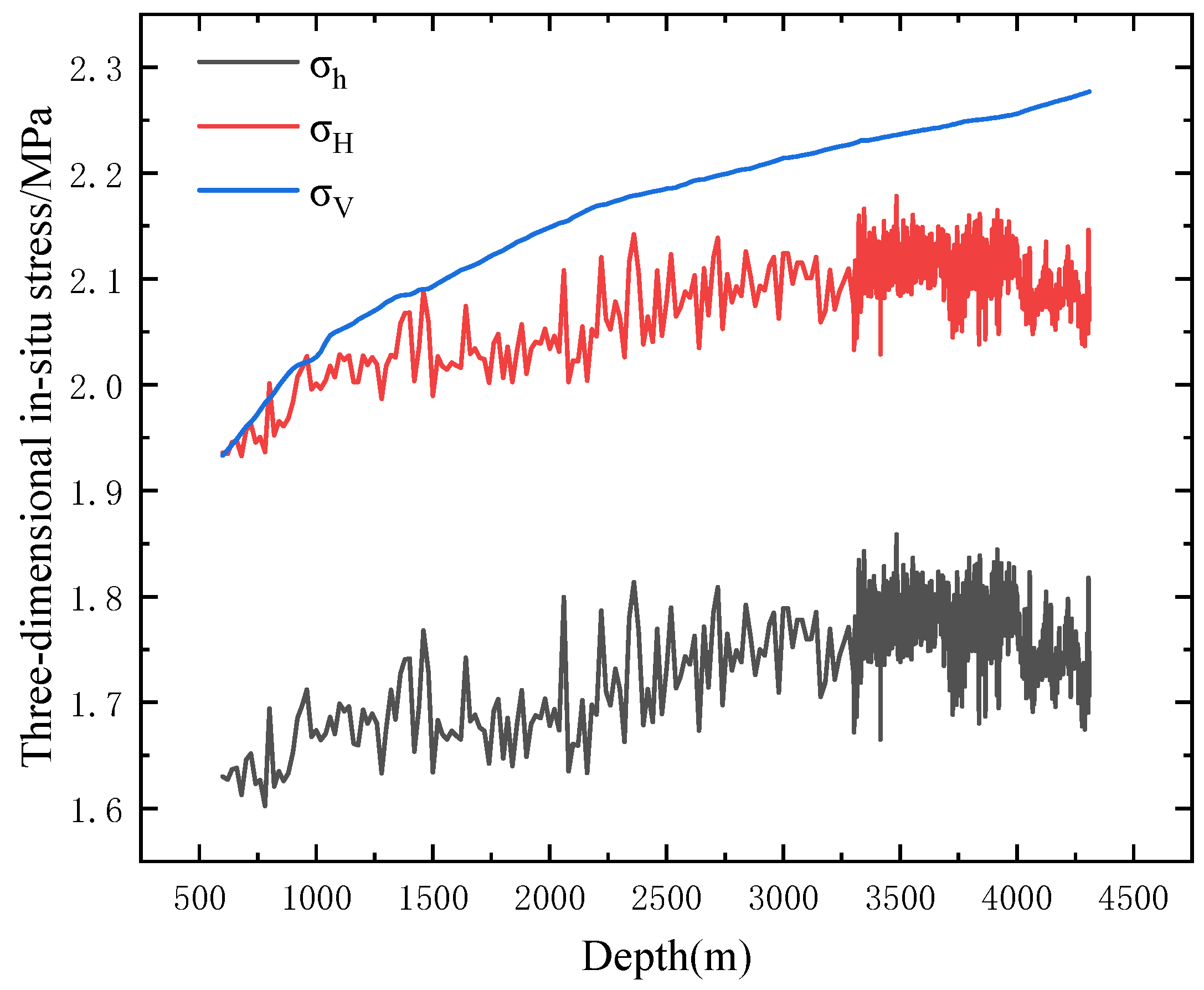
With increasing depth, compressive strength, elastic modulus, and cohesion gradually increase, while the internal friction angle and Poisson’s ratio tend to decrease. Rock mechanical parameters fluctuate significantly both within the same formation and between different formations. Additionally, in-situ stress increases with depth, satisfying the relationship: σ V > σ H > σ h .
(3)
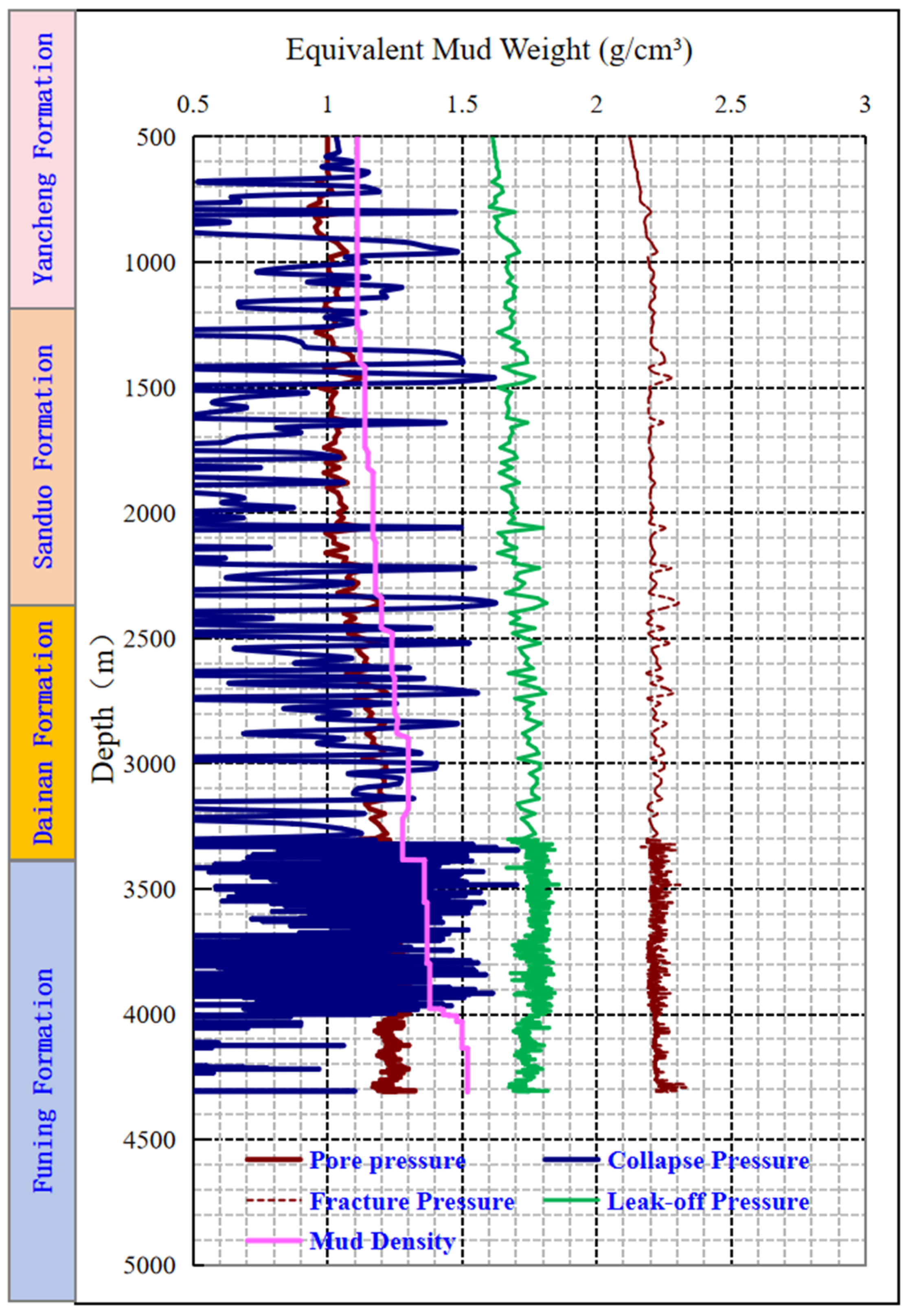
Based on the established formation pressure profiles—including pore pressure, collapse pressure, leakage pressure, and fracture pressure—the following trends in mud density windows were identified: Above 3300 m, the equivalent density of formation pore pressure is below 1.20 g/cm3. Below 3300 m, abnormal high pressure is observed, with a maximum equivalent pore pressure density reaching 1.45 g/cm3. The window between collapse pressure and fracture pressure is narrow, particularly in fracture-developed zones, requiring preventive measures against fluid loss. Generally, the deeper the formation, the narrower the safe density window, increasing the likelihood of borehole collapse.
(4)
It is recommended to select the optimal mud density within the safe window between collapse pressure and fracture pressure. Adjusting the drilling fluid density to a range between 1.183 g/cm3 and 1.5 g/cm3 can effectively improve the wellbore stability in this block. Additionally, drilling fluid properties should be optimized by using long-duration anti-collapse drilling fluids capable of inhibiting shale swelling, thereby improving sealing performance and enhancing borehole stability.

Author Contributions

D.L. and W.C.: writing—original draft, and writing—review and editing, conceptualization. Z.T. and Y.Z.: project administration, resources. H.W.: visualization, methodology, investigation. S.G.: formal analysis, data curation. All authors have read and agreed to the published version of the manuscript.

Funding

This research was funded by National Key Laboratory Open Fund for Mechanisms of Shale Oil and Gas Enrichment and Effective Exploitation—The collapse and instability mechanisms of shale oil reservoirs under drilling fluid circulation conditions (35800000-22-ZC0609-0018).

Data Availability Statement

The datasets used and/or analyzed during the current study available from the corresponding author on reasonable request.

Acknowledgments

Thanks to reviewers and editors for their careful review of this manuscript.

Conflicts of Interest

Authors Daqi Li, Shuyang Gao, Zhichuan Tang and Yayun Zhang were employed by Sinopec Petroleum Engineering Technology Research Institute Co., Ltd. The remaining authors declare that the research was conducted in the absence of any commercial or financial relationships that could be construed as a potential conflict of interest.

References

  1. Wang, J.; Guo, Q.; Zhao, C.; Wang, Y.; Yu, J.; Liu, Z.; Chen, N. Potentials and prospects of shale oil-gas resources in major basins of China. Acta Pet. Sin. 2023, 44, 2033. [Google Scholar]
  2. Qi, W.; Wu, H.; Xie, X.; Lou, Y.; Liu, H. Study on formation rock characteristics and borehole collapse period in northern Jiangsu Basin. China Offshore Oil Gas 2024, 36, 108–118. [Google Scholar]
  3. Fan, Y.; Huang, W.; Wang, Y.; Guo, J. Mechanism and control measures of wellbore instability of large-sized boreholes in ultra-deep wells in western Sichuan Basin. Nat. Gas Ind. 2024, 44, 116–127. [Google Scholar]
  4. Gao, S. Wellbore stability evaluation study for continental shale oil reservoir in northern Jiangsu. Sci. Technol. Eng. 2024, 24, 9350–9356. [Google Scholar]
  5. Zhang, M.; Li, D.; Fan, X. Study on wellbore collapse pressure and instability area around wellbore in broken formation. Fault-Block Oil Gas Field 2024, 319, 16–921. [Google Scholar]
  6. Wang, Y.; Gao, Y.; Yang, Y. Wellbore stability of deep well in western margin thrust belt of Ordos Basin. Sci. Technol. Eng. 2024, 24, 6691–6700. [Google Scholar]
  7. Fan, X.; Meng, C.; Zhang, Q. Research progress in the evaluation theory and control technology of wellbore instability in ultra-deep strata. Nat. Gas Ind. 2024, 44, 159–176. [Google Scholar]
  8. Luo, M.; Gao, D.; Huang, H.; Li, J.; Yang, H.; Zhang, G.; Liu, K. Effects of drilling fluids on shale mechanical properties and wellbore stability. Pet. Drill. Prod. Technol. 2022, 44, 693–700. [Google Scholar]
  9. Zhu, X.; Duan, H.; Sun, Y. Breakthrough and significance of Paleogene continental shale oil exploration in Gaoyou sag, Subei Basin. Acta Pet. Sin. 2023, 44, 1206. [Google Scholar]
  10. Yan, Z.; Liang, B.; Sun, Y.; Duan, H.; Qiu, X. In-situ stress orientation and main controlling factors of deep shale reservoirs in the second member of Paleogene Funing Formation in Gaoyou Sag, Subei Basin. Pet. Geol. Exp. 2024, 46, 1187–1197. [Google Scholar]
  11. Qiu, X.; Qian, S.; Yu, W.; Liu, Q. Main achievements, new understanding and technological progress for oil and gas exploration in North Jiangsu Basin during the 12th Five-Year Plan. China Pet. Explor. 2016, 21, 62. [Google Scholar]
  12. Brown, E.T. ISRM suggested methods. In Rock Characterization Testing and Monitoring; Royal School of Mines: London, UK, 1981. [Google Scholar]
  13. Zhang, W.; Li, Z.; Shou, X.; Liu, W.; Hu, P.; Zhang, J.; Yang, M. Prediction of anti-drilling properties and bit selection for glutenite formations in Mahu Sag. China Pet. Mach. 2023, 51, 9–15. [Google Scholar]
  14. Ji, H.; Zhu, L.; Lou, Y. Evaluation and application of rock drillability of deep thermobaric strata in the South China Sea. Sci. Technol. Eng. 2022, 22, 14707–14713. [Google Scholar]
  15. Guo, J.; Sang, Y.; Meng, B.; Xia, L.; Wang, Y.; Ma, C.; Tan, T.; Yang, B. Study on the Wellbore Instability Mechanism in the Longtan Formation with Soft/Hard Thin Interlayers in the South Sichuan Basin. Processes 2025, 13, 727. [Google Scholar] [CrossRef]
  16. Mohiuddin, M.A.; Khan, K.; Abdulraheem, A.; Al-Majed, A.; Awal, M.R. Analysis of wellbore instability in vertical, directional, and horizontal wells using field data. J. Pet. Sci. Eng. 2007, 55, 83–92. [Google Scholar] [CrossRef]
  17. Yang, Y.; Cai, W.; Xing, X. Mechanism and countermeasure of wellbore instability of fractured formation in Bozhong Block. Sci. Technol. Eng. 2023, 23, 9476–9483. [Google Scholar]
  18. Eaton, B.A. The equation for geopressure prediction from well logs. Soc. Pet. Eng. J. 1975, 15, 371–376. [Google Scholar]
  19. Zhang, J. Pore pressure prediction from well logs: Methods, modifications, and new approaches. Earth Sci. Rev. 2011, 108, 50–63. [Google Scholar] [CrossRef]
  20. Li, S.J.; Cui, Z.; Jiang, Z.X.; Shao, Y.; Liao, W.; Li, L. New method for prediction of shale gas content in continental shale formation using well logs. Appl. Geophys. 2016, 13, 393–405. [Google Scholar] [CrossRef]
  21. Li, L.; Yang, J.; Zhou, B. Rock characteristics and safe drilling cycle of complex formation in middle-deep wells in Bohai. China Offshore Oil Gas 2022, 34, 126–132. [Google Scholar]
  22. Fan, Y.; Wang, J.; Liu, H.; Wu, P. Formation mechanical properties and wellbore stability of the whole well section in Luzhou block. Sci. Technol. Eng. 2020, 20, 6433–6439. [Google Scholar]
  23. Li, J.; Weng, H.; Duan, F.; Yan, W.; Tan, Q. Cases of the influence of drilling fluid type on borehole stability and analysis of anti-collapse mechanism. Sci. Technol. Eng. 2019, 19, 161–167. [Google Scholar]
  24. Moos, D.; Zoback, M.D.; Mastin, L. Predicting mud weight for avoiding wellbore instability in deepwater wells. Int. J. Rock Mech. Min. Sci. 2003, 40, 731–747. [Google Scholar]
  25. Zhang, J. Borehole stability analysis accounting for anisotropies in drilling to weak bedding planes. J. Pet. Sci. Eng. 2013, 103, 129–144. [Google Scholar] [CrossRef]
Figure 1. Thin section and scanning electron microscope identification results of rock samples from the Funing Formation of the Huazhuang Block, Huaye 7 well: (a) Thin section identification results of the Funing Formation, E1f2; (b) Thin section identification results of the Funing Formation, E1f4; (c) Scanning electron microscope identification results of the Funing Formation, E1f2; (d) Scanning electron microscope identification results of the Funing Formation, E1f4.
Processes 13 01151 g001
Figure 2. TAW-2000 Microcomputer-Controlled Electro-Hydraulic Servo Rock Triaxial Testing Machine.
Processes 13 01151 g002
Figure 3. Before and after images of some core samples from the Hua Yuan Block, Hua Ye 7 Well. (a) Uniaxial test before 3984.41–3984.56; (b) Uniaxial test after 3984.41–3984.56; (c) Uniaxial test before 3984.65–3984.75; (d) Uniaxial test after 3984.65–3984.75; (e) Triaxial test before 3984.65–3984.75; (f) Triaxial test after 3984.65–3984.75; (g) Triaxial test before 3971.46–3971.56; (h) Triaxial test after 3971.46–3971.56.
Processes 13 01151 g003
Figure 4. Rock Mechanics Parameter Profile of the Huazhuang Block.
Processes 13 01151 g004
Figure 5. The geological stress profile of well Huaye 7 in the Huazhuang block.
Processes 13 01151 g005
Figure 6. Pressure Profile of Well Huaye 7 in the Huazhuang Block.
Processes 13 01151 g006
Table 1. Full-Rock Mineral Analysis Results for the Funing Formation in the Huazhuang Block (%).
Sample IDStratigraphic IntervalFull-Rock Mineral Content (%)
QuartzPotassium FeldsparPlagioclaseSideriteIron
Dolomite
DolomiteCalcitePyriteTotal ClayGypsum
QKfsAbSidAnkDolCalPyClaysGyp
1-4/10E1f425.22.16.30.03.20.05.72.155.40.0
1-8/1033.22.08.71.13.90.03.40.047.60.0
X-125.62.04.20.00.04.012.51.149.01.6
5-15/40E1f236.60.76.50.01.20.01.60.053.40.0
4-30/5728.80.03.61.80.00.819.50.944.60.0
Table 2. Relative Content of Clay Mineral Types in the Funing Formation of the Huazhuang Block (%).
Well No.Sampe IDWell Depth (m)Stratigraphic IntervalRelative Content of Different Clay Mineral Types
Illite-Smectite Mixed Layer IlliteKaoliniteChloriteIllite-Smectite Ratio
%%%%S%(I/S)
Well Huaye 71-4/103385.3E1f46036/417
Well Huaye 71-8/1033865538/617
Well Huaye 75-15/403997.7E1f25043/720
Well Huaye 74-30/573988.14944/620
Table 3. Experimental Results of Uniaxial/Triaxial Tests in the Huazhuang Block.
BlockStratigraphySample No.Depth (m)Density (g/cm3)Elastic
Modulus (GPa)
Poisson’s
Ratio
Uniaxial
Compressive Strength (MPa)
Cohesion (MPa)Internal Friction
Angle (°)
Confining Pressure (MPa)
Hua
zhuang
E1f2H-13984.41–3984.562.70344.180.20298.2937.1615.80
H-53984.85–39852.65324.530.318154.2332
H-23984.41–3984.562.67235.760.20399.8538.6514.510
H-63971.46–3971.562.66427.450.341153.2432
H-33984.41–3984.562.64733.490.243100.9838.4115.480
H-73984.85–39852.64225.150.316156.2832
H-43984.65–3984.752.61818.610.38997.1137.115.230
H-83984.65–3984.752.60918.550.311151.9232
Disclaimer/Publisher’s Note: The statements, opinions and data contained in all publications are solely those of the individual author(s) and contributor(s) and not of MDPI and/or the editor(s). MDPI and/or the editor(s) disclaim responsibility for any injury to people or property resulting from any ideas, methods, instructions or products referred to in the content.

