1. Introduction
The growing demand for sustainable and efficient energy solutions has intensified interest in small-scale power generation technologies, particularly for residential applications. As highlighted by Bianchi et al. [
1], a significant portion of total energy consumption occurs in the residential sector, making the development of energy-efficient domestic equipment a crucial strategy for reducing overall demand. The Organic Rankine Cycle (ORC) is a well-established thermodynamic technology that efficiently converts thermal energy into mechanical power and electricity. Traditionally used for harnessing low-grade heat sources, ORC systems can also function as direct-fired solutions, where a fuel source evaporates the working fluid. At the residential scale, this approach enables ORC-based combined heat and power (CHP) systems to generate electricity while simultaneously providing thermal energy for space and water heating. According to Dentice d’Accadia et al. [
2], CHP systems serve as a key alternative to traditional energy systems, offering significant energy savings and environmental benefits. Compared to conventional micro-CHP technologies, such as internal combustion engines (ICEs) or Stirling engines, ORC systems provide advantages, including lower noise levels, reduced maintenance requirements, and efficient operation across a wide range of loads [
3]. These characteristics position ORC-CHP systems as a promising solution for enhancing residential energy efficiency and reducing overall energy costs [
4,
5].
Extensive research on ORC systems has explored various aspects, including thermodynamic analysis [
6,
7], different ORC configurations [
8], the selection of working fluids [
9,
10], performance evaluation, component integration [
11,
12], and experimental investigations [
13,
14]. Most studies focus on optimizing system performance under nominal design conditions, emphasizing parameters such as thermodynamic efficiency and electrical output. However, in real-world applications, ORC systems frequently operate under off-design conditions, where fluctuations in heat source quality, ambient conditions, and load demand can impact performance. Several studies employ off-design models to assess system performance under real operating conditions. Dickes et al. [
15] compared different off-design modeling approaches, concluding that semi-empirical models were the most reliable for simulating ORC-based power systems, while polynomial and constant-efficiency models lacked accuracy and robustness. Similarly, Fu et al. [
16] examined the impact of heat source temperature on ORC performance, highlighting the limitations of fixed component efficiencies in off-design modeling. Ibarra et al. [
17] further contributed to the investigation of a small regenerative ORC system’s performance under part-load operation, adjusting the expander speed and working pressure to optimize efficiency. Additionally, other studies [
18,
19] have utilized quasi-steady-state models to simulate ORC performance under varying conditions, such as recovering heat from internal combustion engine exhaust gases.
While off-design models provide valuable insights into ORC performance, only a few studies have extended their application to control strategies, using steady-state calculations to develop optimal control approaches that improve ORC performance as boundary conditions change. Cao and Dai [
20] analyzed a combined gas turbine–ORC system under different operational strategies, while Hu et al. [
21] focused on a control strategy for varying geothermal heat source temperatures. These works primarily employed quasi-steady control strategies, which, although useful, do not fully account for transient behavior when boundary conditions change. Ensuring stable and safe operation requires ORC systems to dynamically adapt to these variations. Consequently, the development of robust control strategies that sustain efficient operation under changing conditions is critical for the broader adoption of ORC technology in practical applications. To address this limitation, dynamic models offer a more sophisticated approach by enabling systems to return to equilibrium quickly after disturbances. These models provide a more detailed and responsive framework for changes in boundary conditions, such as variations in heat source or sink temperatures [
22,
23].
Although improvements made in computational science have enabled the development of advanced control methods, including optimal controllers, adaptive controllers, and model predictive controllers, state-of-the-art ORC systems still predominantly rely on proportional–integral–derivative (PID) controllers [
24]. These controllers remain popular due to their simplicity and widespread availability as electronic modules [
25]. Quoilin et al. [
26] investigated three PI-based control strategies for an ORC with a scroll expander recovering waste heat from an ICE. The pump speed and expander were used as control variables and the controller parameters were tuned manually, concluding that optimizing the evaporation temperature based on offline steady-state calculations led to superior performance. Expanding ORC control methodologies, Ni et al. [
27] studied the dynamic performance of a solar ORC system under fluctuating solar irradiation. They implemented two PID controllers to regulate evaporation pressure and superheating by adjusting pump and expander speeds. The controlled system demonstrated a 24% increase in energy output compared to an uncontrolled system. Similarly, Luong et al. [
28] developed a load-following PI control strategy for an ORC system recovering waste heat from a heavy-duty diesel powertrain. Their approach employed three independent PI controllers to manage evaporation pressure, condensation pressure, and load demand by adjusting the sink fluid mass flow rate and throttle valves. Further refining control strategies, Li et al. [
29] designed a dynamic model for a small-scale solar ORC system with thermal storage. A PI controller was implemented to maintain a stable degree of superheating by regulating pump speed, ensuring reliable system operation. Lu [
30] compared an ORC and an oil storage–ORC system for recovering waste heat from an ICE. PID controllers were used to regulate pump and expander speeds, optimizing evaporator pressure and superheating. The oil storage system reduced dynamic oscillations but increased costs per unit of power. Jolevski et al. [
31] developed a control structure for an ORC system using the non-square relative gain array method. A state-space model was linearized to analyze control variable coupling. PI controllers were then tuned for robustness and high bandwidth, achieving satisfactory control performance for constant setpoints. Marchionni et al. [
32] investigated a 40 kW ORC system and compared four PI-based control strategies. The turbine inlet temperature was maintained as the primary control variable, ensuring optimal power output and sufficient superheating. The most effective strategies involved turbine speed control, while pump-based approaches better maintained net power output under changing heat source conditions. In the realm of automotive ORC applications, Imran et al. [
33] implemented a PID control strategy for waste heat recovery in long-haul trucks. Their study evaluated two approaches: (i) controlling pump speed and a bypass valve for exhaust gas flow and (ii) controlling pump speed and a turbine inlet throttling valve. The latter strategy resulted in improved net power output and system efficiency. Yang et al. [
34] further advanced ORC vehicle waste heat recovery by developing a hierarchical controller integrating an internal optimizer for evaporating and condensing pressure regulation with PID-based adjustments. Finally, Pili et al. [
23] studied the dynamic performance of an ORC unit recovering waste heat from a billet furnace. Their approach employed three independent PI controllers to regulate evaporator outlet temperature, pressure, and condensation pressure. However, their study also noted that control effectiveness declined as heat source variations increased.
This work offers an original contribution via the following:
Developing a comprehensive control strategy for an ORC-based micro-CHP system, integrating steady-state off-design modeling with a dynamic control approach to improve adaptability in real-world conditions.
Employing a charge-sensitive steady-state model that eliminates the need for predefined subcooling and superheating values, enabling predictive performance characterization across a wide range of boundary conditions. This modeling approach allows for the generation of control maps that identify stable and optimal operating regions tailored to dynamic residential thermal demands.
Implementing a PID-based dynamic control strategy, informed by the steady-state maps, to ensure rapid response, robustness, and efficiency during system start-up and fluctuations in hot water consumption. The approach is designed to manage thermal inertia and protect components under transient conditions, while remaining practical for implementation in embedded control hardware.
Providing a scalable and robust control framework that can be adapted to different thermal loads and demand profiles by tuning control map boundaries and PID parameters. This positions the system as a viable solution for widespread deployment of ORC-based micro-CHP in residential settings, where reliability, fast response, and ease of implementation are critical.
Unlike conventional PID applications, the control strategy proposed in this work is grounded in a steady-state off-design, charge-sensitive model that produces detailed control maps for identifying admissible and optimal operating regions. These maps inform a multi-stage, empirically defined transient control algorithm, specifically designed for the safe and efficient operation of ORC micro-CHP systems under dynamically varying thermal loads. The novelty of the proposed approach lies in its integration of model-informed steady-state characterization with real-time PID coordination, enabling rapid system start-up, seamless transitions between boiler and CHP modes, and effective responsiveness to user-driven thermal demands. This experimentally validated strategy provides a practical and scalable solution tailored to the unique constraints of small-scale residential ORC systems.
This paper is structured as follows:
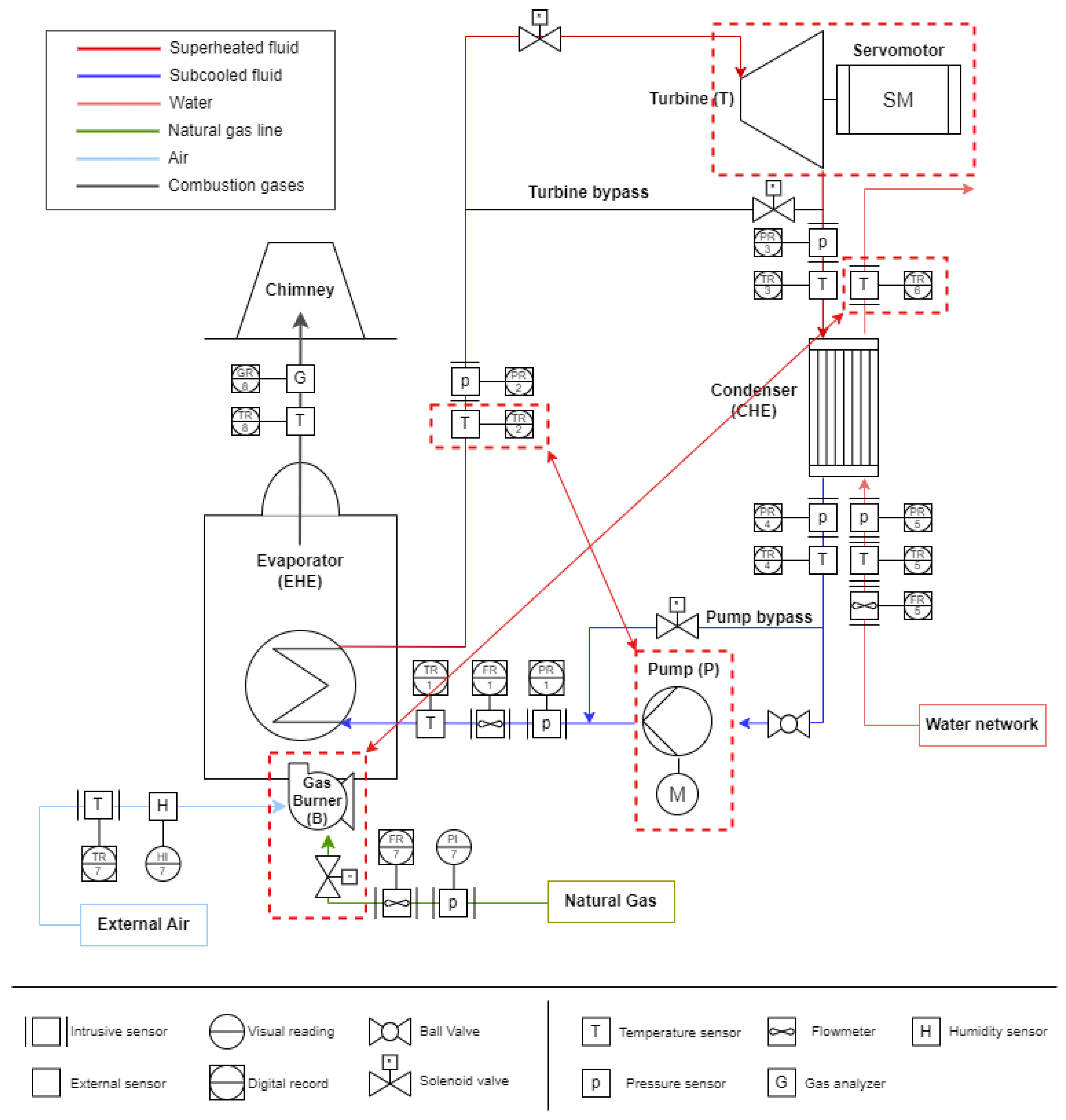
Section 2 presents the experimental setup and describes the components and instrumentation of the ORC-based micro-CHP system. It also introduces the charge-sensitive off-design model, which is used to characterize system behavior.
Section 3 focuses on steady-state control, including the generation of control maps and the identification of optimal operating regions.
Section 4 outlines the transient control strategy, based on PID controllers, developed to manage variations in start-up and user demand. Finally,
Section 5 summarizes the main findings and discusses opportunities for future work.
3. Steady-State Control
The ORC system operates with three primary control variables:
, the combustion heat power, regulated by the control valve governing the natural gas flow rate .
, the rotational speed of the working fluid volumetric pump (P) responsible for circulating the working fluid, regulated through a variable-speed motor controller.
, the rotational speed of the expander (T), managed through a servomotor.
For a given set of boundary conditions, including natural gas supply, ambient temperature, and user input conditions , these three control parameters determine the condenser outlet water temperature to the user and the overall thermodynamic state of the ORC system. The operating point is considered admissible only if the following constraints are satisfied:
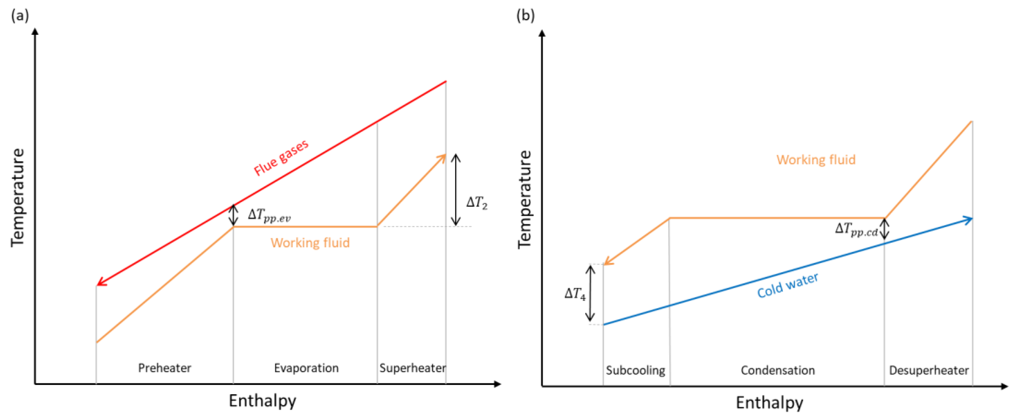
The manufacturer specifies conditions (1) and (2) to prevent mechanical stress and overpressure damage and avoid excessive thermal loads that could degrade the expander. Condition (3) ensures a minimum level of superheating, illustrated in
Figure 5a, to avoid condensation within the expander. Although condition (4) is not a strict requirement, it prevents operation too close to the pinch point in the condenser, illustrated in
Figure 5b, imposing a variable lower bound on the condenser inlet temperature
. In condition (5), the servomotor currently coupled to the expander sets a limitation of
, although the expander itself can operate up to
. Other constraints, including total condensation of the working fluid at the condenser’s exit, are virtually guaranteed under typical operating conditions and do not require explicit imposition.
An operating point is considered optimal when, within the admissible region, it results in the maximum thermodynamic efficiency
:
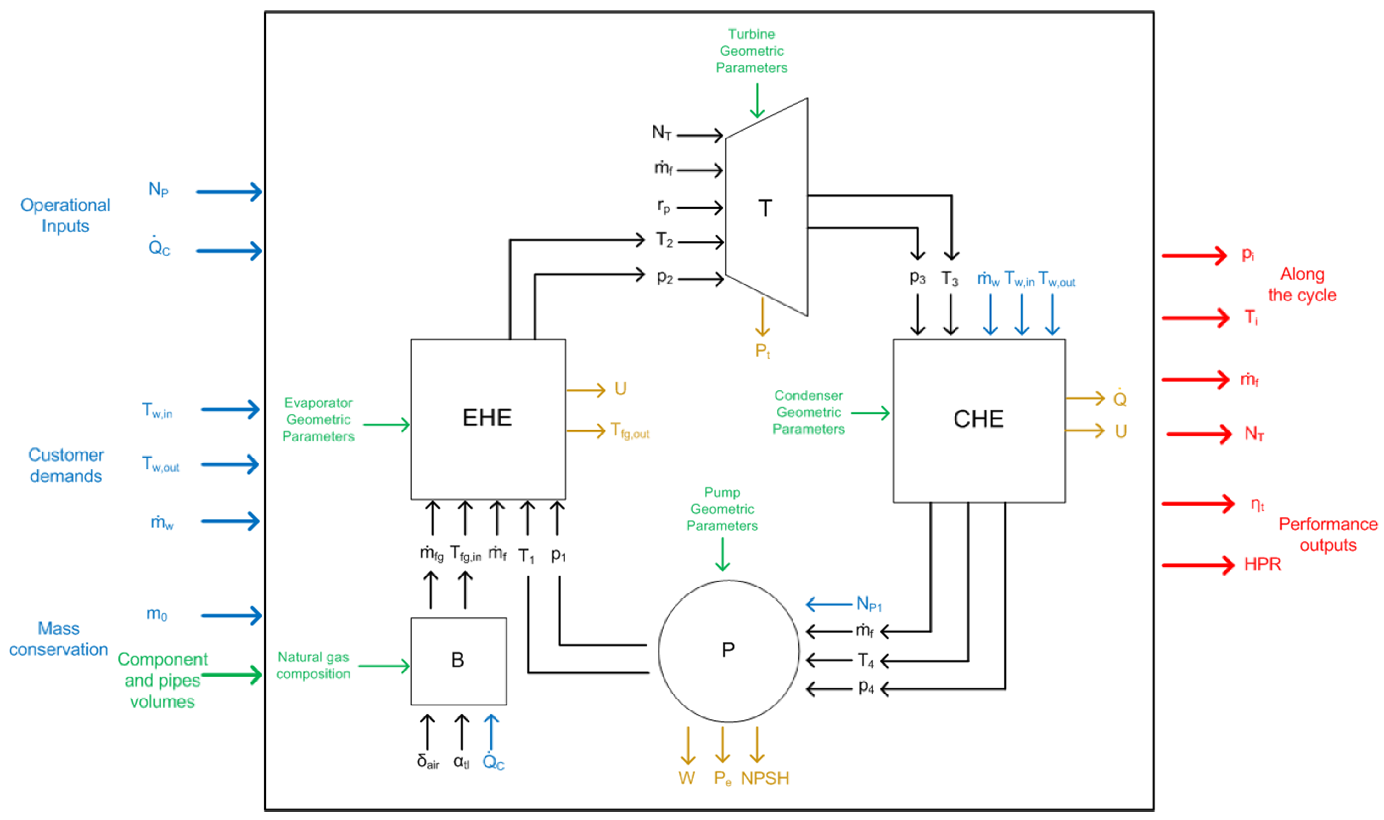
where the energy balances for the main components of the ORC system are presented next, with evaporator, turbine, condenser and pump corresponding to equations 7, 8, 9 and 10, respectively
In the charge-sensitive model, the enthalpy values are computed from pressure and temperature pairs at each state point, which are iteratively adjusted to satisfy the imposed operating conditions, user demand, and mass conservation. In the experimental setup, the pressure and temperature at each point are measured using transducers and acquired via the LabVIEW interface, where the corresponding enthalpies are calculated using thermophysical property libraries.
3.1. Numerical Stability and Algorithm Performance Analysis
Prior to applying the model for control optimization, it is crucial to assess its numerical stability and the physical consistency of the algorithm used to solve it. This includes analyzing ignition dynamics, stability, convergence speed, and error behavior. Additionally, understanding the existence and uniqueness of solutions, multiple solutions, or no solutions and distinguishing between stable and unstable solutions is critical. These algorithmic and physical aspects are closely interconnected. To achieve this goal, it is advisable to use the model’s innate inputs, comprehensively defining the user conditions, including , and keeping the expander rotational speed as an output.
To explore these characteristics, a grid-based analysis was performed, varying the combustion heat power and pump rotational speed (
,
). The analysis was conducted under typical natural gas, ambient, and user hot water conditions
, with a fluid charge of
The results are shown in
Figure 6, which maps the level curves of key ORC operational variables in the
control plane
. Notably, the model yields no valid solution beyond the dashed line, suggesting the absence of admissible steady-state operating conditions in that region.
For a given combustion heat power (), increasing the pump rotational speed () requires a corresponding increase in the expander rotational speed to accommodate the higher mass flow rate. As increases, the evaporation pressure also rises, which in turn limits heat transfer within the evaporator. This restriction results in a lower outlet temperature and a decrease in the superheating temperature. On the other hand, since the condensing pressure remains relatively stable, the increase in evaporation pressure leads to a higher pressure ratio across the expander. This higher pressure ratio enhances the expander’s isentropic efficiency, ultimately causing a reduction in its outlet temperature.
Conversely, for a given pump rotational speed (), increasing the combustion heat power () requires only a minor adjustment in the expander rotational speed, as the mass flow rate remains nearly constant while the fluid properties at the expander inlet change. This increase in enhances the heat input to the cycle but does not significantly affect the evaporation pressure. As a result, the outlet temperature and the degree of superheating rise. Since both the evaporation and condensing pressures remain relatively stable, the pressure ratio remains unchanged, meaning that the expander’s isentropic efficiency and outlet temperature are not significantly influenced by this variation in heat input.
The analysis revealed that the ORC system has a limited operational region, where stable and efficient performance is possible. Three primary regions in the control plane where steady-state solutions exist, or fail to exist, are qualitatively illustrated in
Figure 7:
Region I: A single stable and admissible solution is present. However, under certain user conditions and within specific sub-regions, one or two additional numerical solutions may appear. These additional solutions are unstable and either physically incorrect or of no practical interest.
Region II: A single, apparently stable solution exists, but it is either inadmissible or uninteresting from a practical standpoint.
Region III: A region beyond Zones I and II where no solution is found. The model fails to converge to a valid steady state due to operational limits being exceeded.
Numerically unstable solutions within Regions I and II can be identified through a sensitivity analysis, which involves careful variation of the initial guesses (iteration seed) for key state variables under specific user conditions and sub-regions. This process evaluates the robustness of the solution by observing whether the algorithm converges into a consistent and physically meaningful state. Unstable solutions often exhibit non-admissibility or yield physically implausible values, such as negative superheat or expander rotation speeds that fall outside the viable range of the turbine’s performance curve. In particular, at high pump rotational speeds, the increased mass flow rate may prevent the working fluid from reaching the necessary superheat at the evaporator outlet, resulting in non-physical, two-phase flow at the expander inlet. Conversely, at very low expander rotational speeds, the model may fail to satisfy the turbine’s characteristic flow equation:
leading to divergence of the algorithm due to the lack of a physically consistent solution. If the solution appears physically unrealistic, it is discarded. In some cases, solutions that appear physically plausible may still exhibit numerical instability, which could stem from model stiffness near control boundaries and may complicate the real-time control of the ORC system. These behaviors are intrinsic to the specific model and are particularly pronounced near the transition between admissible and inadmissible operating regions.
Figure 6 shows the level lines of thermodynamic efficiency for the ORC system within the
control plane, while
Figure 7 highlights Point B as the optimal operating point, corresponding to the highest achievable efficiency. However, under different user conditions, Point A may fall within the admissible region with an even higher thermodynamic efficiency than Point B, making it the preferable operating point. Notably, the nominal ORC operating point, where the thermodynamic efficiency reaches its absolute maximum, is located relatively close to this region in
Figure 6.
3.2. Steady-State Control Mapping of the ORC System
An updated ORC model and algorithm enable the computationally intensive generation of ORC control maps for any given user condition. All previous input values (
) remain unchanged, except that
now replaces
as an input/output variable.
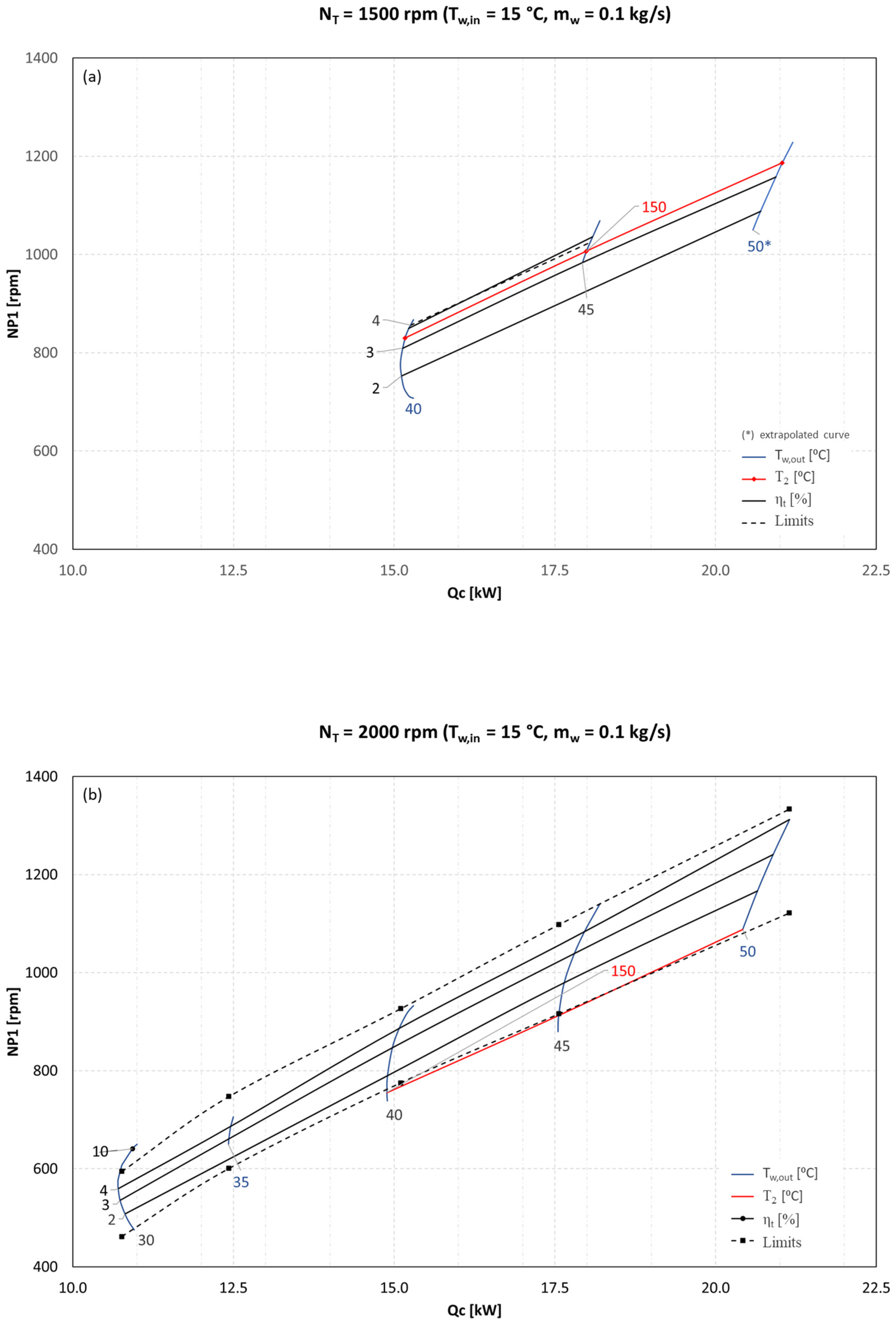
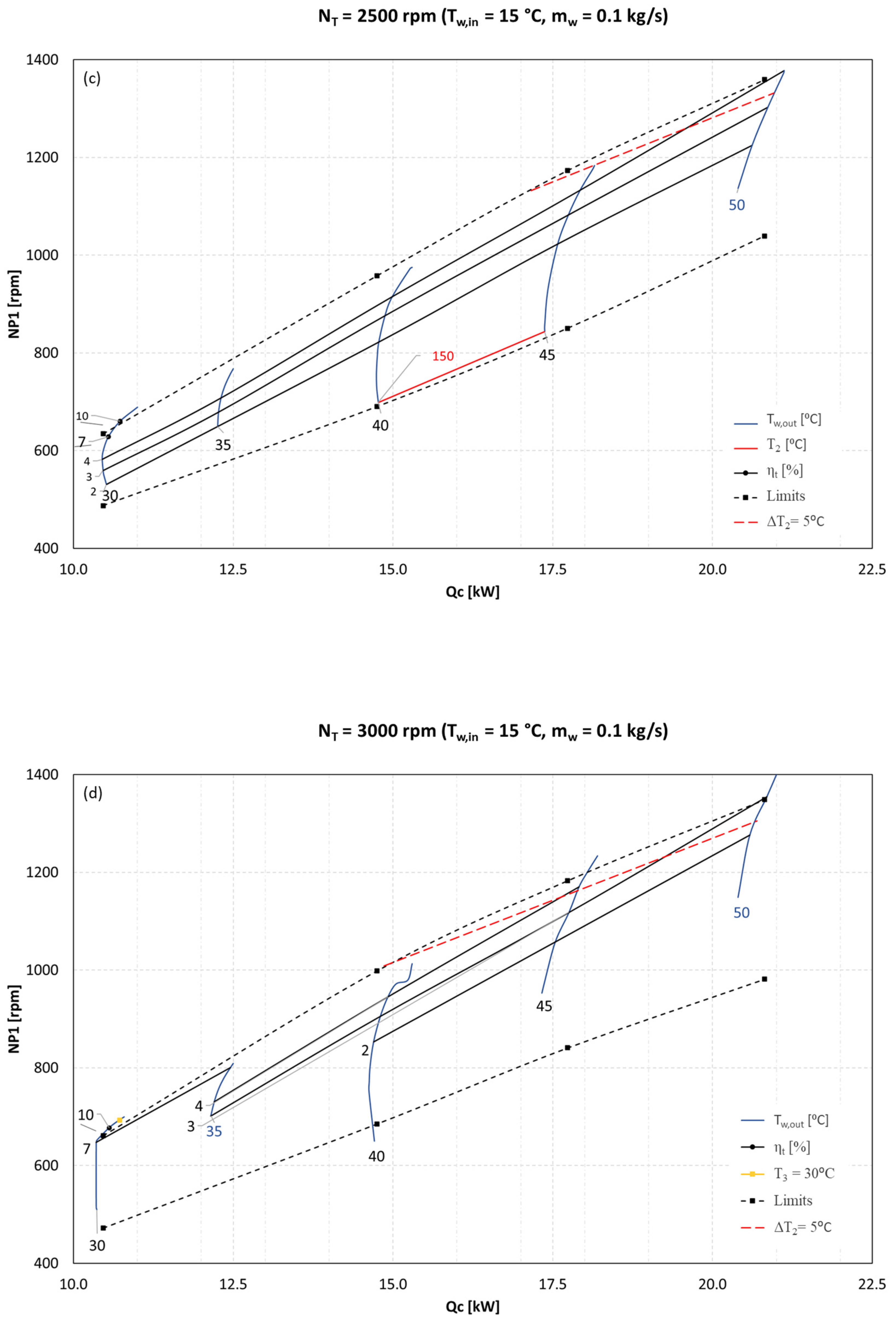
Figure 8 presents four representative control maps for
. For a fixed expander speed
, each
control map includes the following key elements:
Upper and lower limiting lines, defining the boundaries of steady operation.
A level line at , marking the upper admissible limit. If this line lies within the steady-state region (for ), operation below this temperature is inadmissible.
A level line at , representing the lower admissible limit for superheating. When this line intersects the steady-state region (for ), any operation beyond this temperature limit is deemed inadmissible.
Level lines for condenser outlet temperature .
Level lines for the thermodynamic efficiency , illustrating performance across different control settings.
For the four selected expander rotation speeds, no additional constraints, such as or , further restrict ORC operation. As a result, their level lines are not depicted in the figure.
These results demonstrate that at the lowest expander speed 1500 rpm, the ORC has virtually no acceptable operating region, as the level line lies near the upper boundary of the steady-state region, severely restricting operation. Conversely, at higher rotation speeds, the ORC exhibits a broader operation range. However, additional constraints, such as the minimum required superheat degree at the expander inlet and outlet temperature of the expander (, impose further operational limits.
A particularly significant physical interpretation can be attributed to the upper limiting line of the steady-state operating region in the control plane for a given expander speed. Above this boundary, a conflict arises between the speed controllers of the pump and the expander. The pump’s speed controller attempts to enforce a mass flow rate
, which scales almost linearly with
. However, the expander speed controller, constrained to maintain a fixed rotational speed
, cannot accommodate the increased flow rate. As a result, the ORC system exhibits unstable behavior, characterized by abrupt pressure fluctuations at the expander inlet. This instability is confirmed by the data presented in
Figure 9.
As shown in
Figure 9, this conflict may be resolved by increasing the expander speed beyond a threshold that is dependent on the input conditions and the control variables
and
. A similar interpretation applies to the lower boundary of the steady-state operating region. When the expander speed is sufficiently low (e.g.,
), this boundary falls within the inadmissible region, making it non-restrictive since the system cannot operate stably under such conditions.
The primary challenge faced by the control algorithm is that the highest achievable thermodynamic efficiency of the ORC, corresponding to the optimal operating point, occurs at the upper boundary of the steady-state operating region. This boundary intersects with the level line of the condenser outlet temperature for a given expander speed, imposing an operational constraint.
The analysis of the control maps suggests that increasing the expander speed, potentially setting , could be advantageous, as higher expander speeds improve thermodynamic efficiency at the optimal point. However, to maintain the desired condenser outlet temperature, precise combustion heat power control is required due to the steep slope of the level lines in the relationship. Additionally, the optimal operating point can be further refined by regulating the expander inlet temperature through pump speed control, ensuring stability and maximizing system performance.
4. Transient Control Strategy
To guide the development and implementation of the control strategy for the ORC-based micro-CHP system, a structured methodology was adopted, as illustrated in
Figure 10. This flowchart outlines the step-by-step process, from defining the control objectives and identifying key variables to developing a charge-sensitive off-design model, generating control maps, and designing the PID-based control logic. The methodology also includes the implementation of a staged empirical algorithm and its experimental validation under dynamic operating conditions. This systematic approach ensures that the control system not only meets performance requirements under steady-state and transient regimes but is also robust and adaptable to real-world user demand fluctuations.
To achieve optimal steady-state operation while meeting hot water demands, each of the three controllers must fulfill a specific objective:
The second phase of the ORC control strategy focuses on dynamic objectives:
Rapid and stable transient response, ensuring a fast and secure transition to optimal steady-state conditions during start-up or variations in user demand, minimizing undesirable overshoots or undershoots in key ORC variables.
To achieve these objectives, the steady-state control parameters were pre-determined as
= 2000 rpm and
= 120 °C, without conducting a full steady-state optimization. This decision was based on experimental tests and model calibration, which revealed design limitations in the expander’s magnetic coupling and servomotor assembly, as reported in Santos et al. [
38]. Consequently, the thermodynamic efficiency
is expected to remain slightly below its theoretical maximum.
The dynamic control strategy employs two independent PID controllers:
The pump controller regulates the pair , where is the manipulated variable (pump speed) and (evaporator outlet temperature) is the controlled variable.
The burner controller regulates the pair , where is the manipulated variable (combustion heat power) and (condenser outlet water temperature) is the controlled variable.
Additionally, the expander’s servomotor operates with an autonomous controller to maintain .
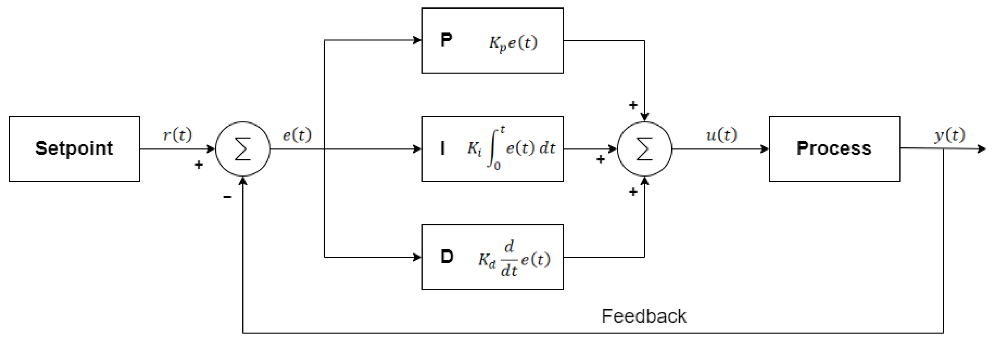
It is worth noting that PID controllers are widely used in industrial control systems due to their effectiveness in maintaining system stability. Essentially, a PID controller continuously links the setpoint value
with the current process variable
, calculates the error
, and determines an optimized control response
to drive the error toward zero. The controller (PID), illustrated in
Figure 11, adjusts the manipulated variable based on the error between the setpoint and the measured process output, with sensor feedback explicitly shown to reflect the closed-loop configuration.
The PID controller continuously compares the setpoint
with the process variable
, calculating the error as
The controller then computes the control signal
using the following equation:
where
is the proportional gain, determining the response to the current error;
is the integral time constant, controlling the contribution of the accumulated error over time;
is the derivative time constant, which modulates the response to the rate of change of the error;
is the integration variable, distinct from time .
The initial PID gains were obtained using the open-loop Ziegler–Nichols calibration method [
40], applied individually to each control loop with the system in manual mode to isolate and characterize the dynamic response of each manipulated variable. This procedure was conducted under controlled conditions to ensure safe operation. The resulting coefficients are presented in
Table 2. However, when both control loops were simultaneously activated in closed-loop mode, the interaction between controllers introduced instability, revealing the limitations of Ziegler–Nichols tuning for multivariable systems. Therefore, empirical fine-tuning was performed to ensure stable and coordinated system behavior.
Consequently, a manual empirical tuning procedure was carried out, involving iterative adjustment of the PID parameters based on the observed system response to step changes in the setpoints and disturbances. Each controller was tuned independently, with the other held constant to minimize interaction effects. The tuning aimed to improve stability and responsiveness by evaluating performance indicators such as rise time, overshoot, settling time, and steady-state error. This iterative process ensured coordinated behavior of both controllers and optimal system performance under varying operating conditions.
The control algorithm governing system start-up, from initial switch-on to steady-state operation, consists of six different stages. Throughout these stages, the three controllers operate in different modes (off, preset, or PID), each following specific predefined parameters, including the setpoint of the controlled variables, specific controller coefficients, and permissible control variable ranges. Additionally, three start-up procedures were developed for the evaporator, based on the temperature conditions at a reference point within the component. These are cold start up, semi-cold start up, and hot start up.
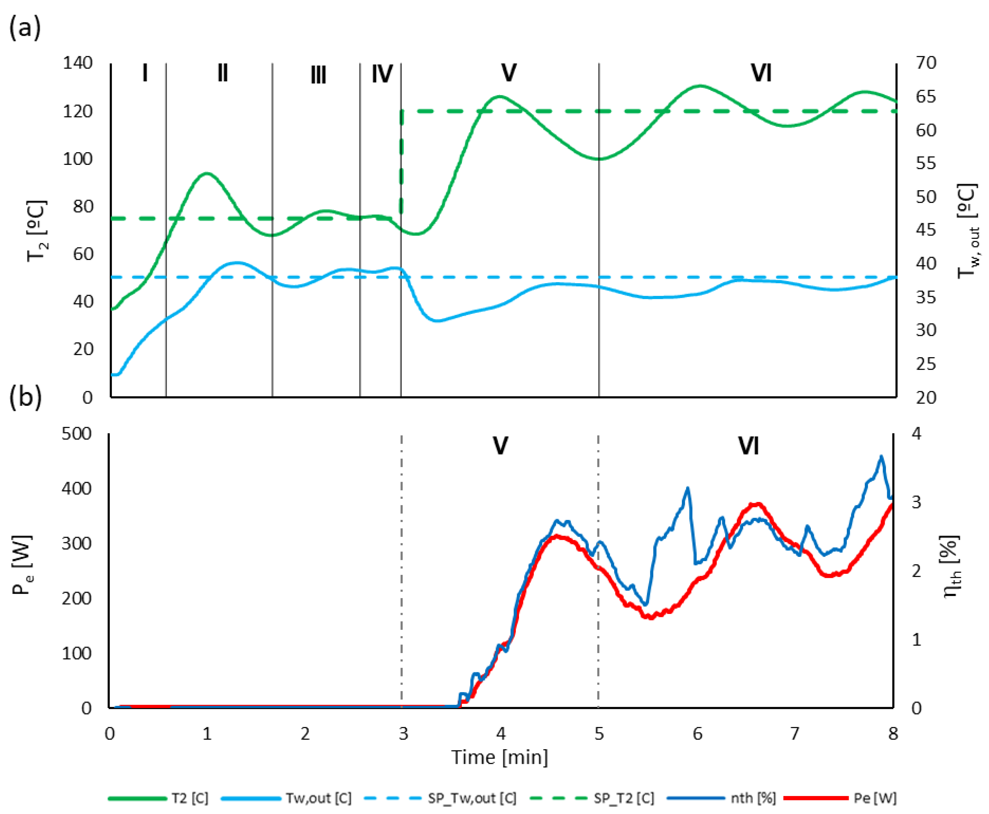
Figure 12 illustrates an example of a semi-cold start-up process. Throughout all stages, the pump speed controller
operates in PID, but its parameters evolve dynamically to optimize system response and prevent instability.
During stages I to IV, the system operates in simple boiler mode, with vapor bypassing the expander and flowing predominantly through the bypass. In stages I to III, the burner controller remains in preset mode at a constant combustion heat power of (set to 20 kW). This value was carefully selected to prevent excessive overshooting of the evaporator outlet temperature while ensuring a rapid increase in the condenser outlet water temperature.
The transition from stage I to stage II occurs when the evaporator outlet temperature reaches , where is the controller’s setpoint in boiler mode (75 °C in this case). The shift from stage II to stage III follows the first overshoot and subsequent undershoot of the evaporator outlet temperature. Throughout these initial stages, adjustments to the pump controller settings help accelerate the heating process while avoiding hazardous temperature overshoots. The transition from stage III to stage IV is more complex, requiring the evaporator outlet temperature to stabilize near its setpoint while the condenser outlet water temperature approaches or exceeds the user-defined target. At this stage, the pump PID controller adopts its steady-state configuration, and the burner controller transitions from preset mode to PID mode, allowing the system to reach full steady-state operation in boiler mode.
During stages V and VI, the system shifts from boiler-only operation to CHP mode, where it simultaneously supplies thermal energy and generates electrical power. The transition from stage IV to stage V occurs when it becomes safe to operate the expander, ensuring that the superheat degree at the expander inlet is sufficiently high to prevent condensation. In this case, a minimum superheat of 20 °C is conservatively imposed. Furthermore, to prevent cavitation in pump P1, which could result from excessive pressure drops at the expander outlet, two safety conditions must be met: a net positive suction heat above 9 m.c.f. and a pump outlet pressure exceeding 260 kPa. Once these conditions are satisfied, the expander’s bypass valve closes, directing the entire flow through the expander, which then accelerates. When the expander speed reaches the required value, the servomotor controller locks the rotor at its predefined setpoint
and maintains it. At this stage, the PID coefficients of the pump controller are updated, while the burner controller settings remain unchanged. The pump controller setpoint transitions from
(boiler mode) to
= 120 °C (CHP mode), establishing a stable control strategy. However, a collateral issue remains concerning user outlet water temperature (see
Figure 12). After the initial overshoot of
, the system proceeds to stage VI at the bottom of this undershoot. To accelerate stabilization in CHP mode and align system performance with user demand, a final adjustment is applied to the burner controller.
The effectiveness of the transient control algorithm, compared to manual regulation, is clearly demonstrated in
Figure 13. The system achieves a significantly faster response time and better stabilization of the hot water temperature at the user’s setpoint. With automatic control, CHP mode is reached in just 3 min, while manual control takes 5 min and 30 s to achieve the same conditions. This advanced control strategy fully automates the ORC process, not only reducing the time to reach the target hot water temperature but also enhancing the efficiency of electricity production.
The temperature response of the system, particularly at the evaporator outlet (T
2), exhibits underdamped behavior during transient regimes, with overshoots reaching approximately 30 °C in
Figure 12a and around 20 °C in
Figure 13b and
Figure 14a. This behavior results primarily from the thermal inertia of the system, especially within the evaporator, whose significant steel mass delays thermal equilibrium, despite the fast response capability of the pump and burner actuators. During start-up, control actions prioritize quickly reaching safe conditions, such as achieving sufficient superheat at the expander inlet, before switching to cogeneration mode. In the initial stages, the burner controller is kept in preset mode, and only the pump controller actively accelerates the heating process while avoiding hazardous temperature overshoots. Although the overshoots remain within safe operational margins, their reduction is a key objective for future work. More advanced control strategies, such as model predictive control or gain scheduling, may offer improved damping by better anticipating actuator behavior and accounting for system delays.
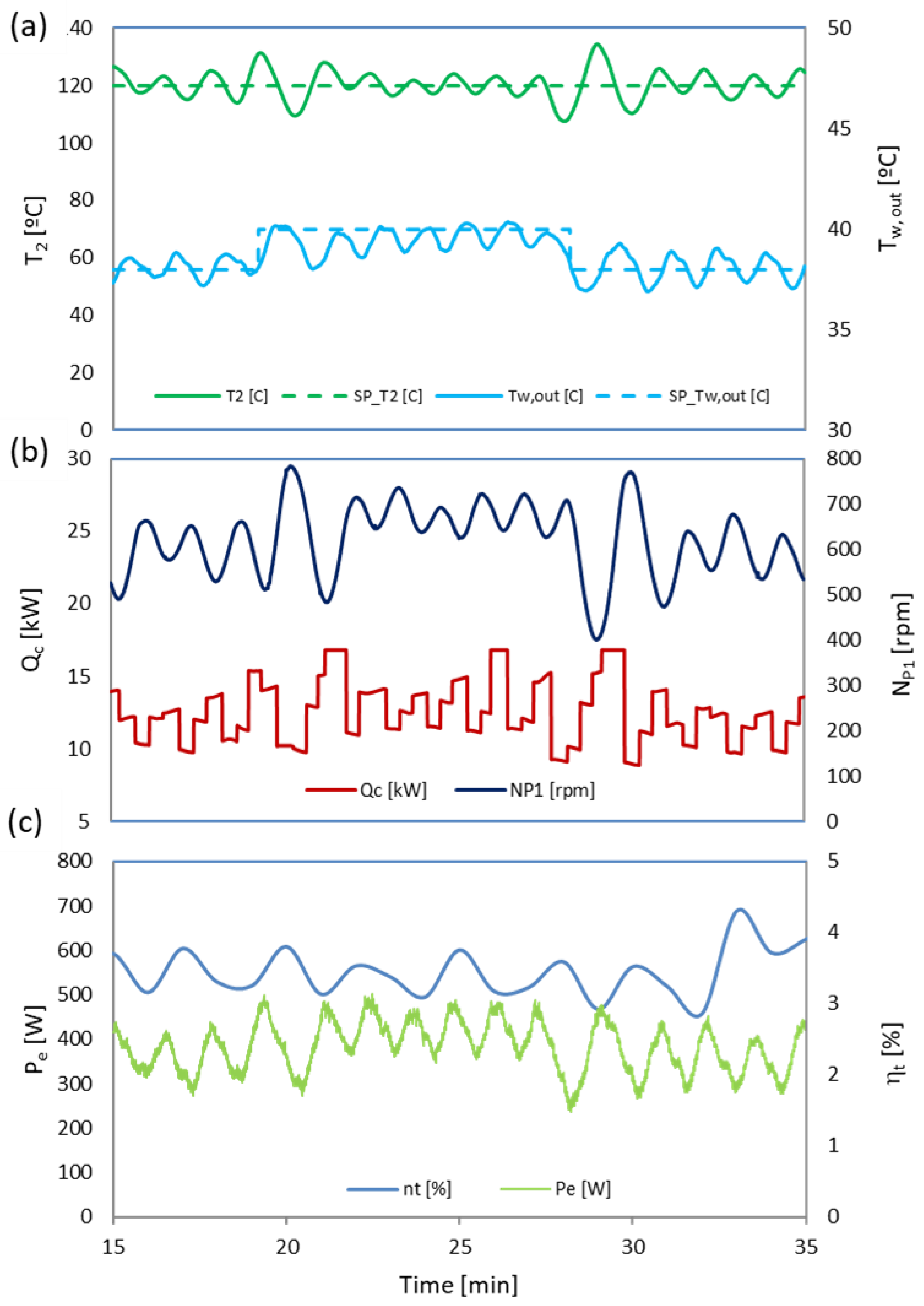
The effectiveness of the dynamic control system is further highlighted in response to a user adjustment of the setpoint. In
Figure 14, the hot water outlet temperature is increased from 38 °C to 40 °C, followed by a return to the original value ten minutes later. This controlled variation results in a symmetrical shift in system behavior.
Figure 14a displays the response of the controlled variables
, demonstrating the system’s ability to adapt and stabilize following setpoint changes. Following the user’s adjustment, both temperatures exhibit greater fluctuations than in steady-state operation; however, their amplitude gradually decreases over time, indicating that the system effectively dampens oscillations and returns to stability.
Figure 14b presents the corresponding behavior of the control variables, while
Figure 14c highlights the fluctuations in the generated electrical power. The developed control system successfully manages user requests, ensuring that the system remains both stable and secure. Under these conditions, the user’s thermal power demand ranges between 10 and 15 kW, resulting in an electrical power output of 300–500 W. The system achieves a thermodynamic efficiency of 3–4%, which could be further optimized by refining pump speed control. Instead of maintaining the evaporator outlet temperature at a fixed 120 °C, adjusting the pump speed dynamically could improve efficiency by optimizing evaporation pressure and superheating.
5. Conclusions
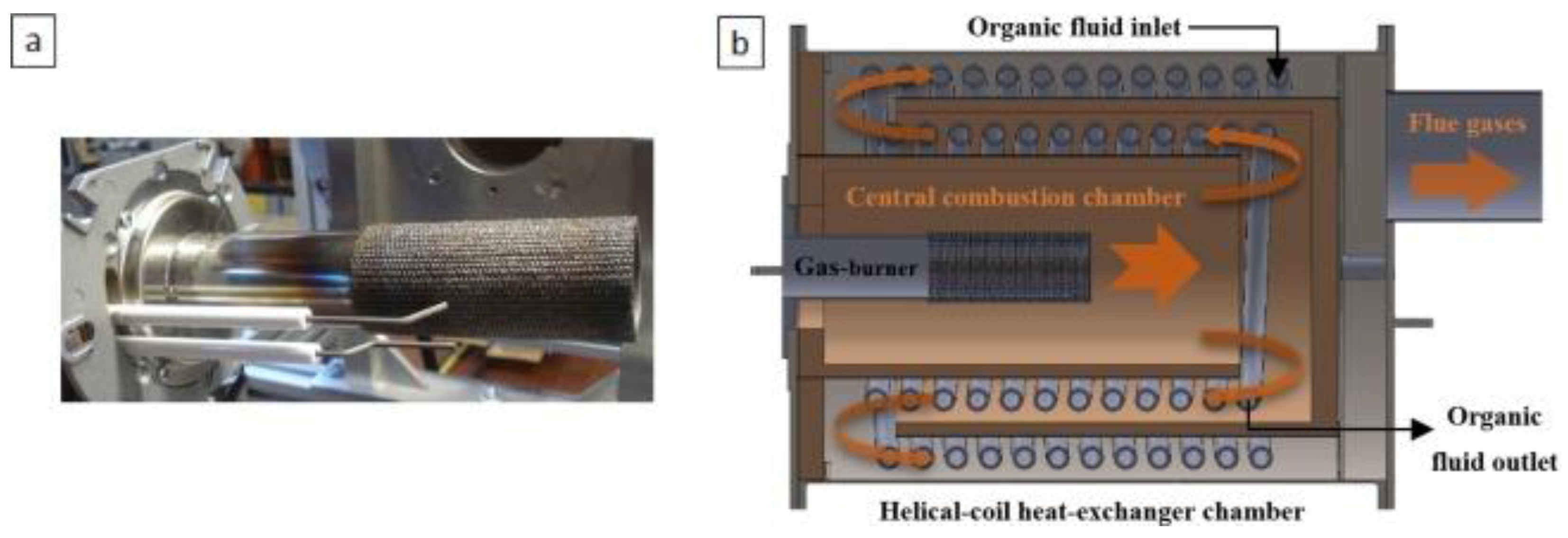
To design an effective control strategy for an ORC-based micro-CHP system, a steady-state, off-design, charge-sensitive, and semi-empirical model was developed. This fully predictive model is tailored to satisfy typical domestic hot water requirements () while enabling the simultaneous generation of up to 2 kW of electricity. The system utilizes R245fa as the working fluid, which is directly evaporated by a natural gas burner, serving as the ORC’s heat source. The primary control variables include the combustion heat power, along with the rotational speeds of the volumetric pump and the scroll expander.
Under varying user demand conditions for both hot and cold sources, the ORC model generates the steady-state control maps as level lines of key operational variables across planes for different expander speeds. The analysis of the ORC steady-state control strategy provides several key insights:
In certain control planes, the admissible operating region is constrained by upper and/or lower boundaries. Beyond these limits, the expander and pump speed controllers become incompatible, leading to unstable operation characterized by pressure fluctuations at the expander inlet. Additional limitations include the maximum allowable expander inlet temperature and the minimum permissible vapor superheat at the expander inlet.
To maintain the desired hot water outlet temperature, combustion heat power must be carefully controlled. For achieving maximum thermodynamic efficiency at the optimal point in the plane, the pump speed control is the most effective variable, as it directly governs the evaporator outlet fluid temperature, while the expander speed can remain at an optimal constant value.
An empirical transient control strategy is implemented using two PID controllers for the variable pairs and , along with an autonomous servomotor controller for . This strategy dynamically adjusts each controller’s state (on/off) and mode (preset/PID) across six stages. The control sequence first operates in simple boiler mode (stages I–IV) before transitioning to CHP mode (stages V–VI). Notable performance results during a semi-cold start-up include the following:
Expander inlet temperature remains within safe limits, preventing overheating.
In simple boiler mode, the condenser outlet water temperature stabilizes within within 1.5 min.
Steady-state CHP operation is reached within 5–7 min.
During CHP operation, the water temperature supplied to the user fluctuates by , while the electrical power output varies by .
Effective transient management of user demand variations, though with some remaining fluctuations in the expander outlet temperature (±12–15 °C) and electrical power (±100 W).
Limitations and Future Work
Despite the promising results demonstrated in both simulation and experimental testing, the present study has some limitations. The steady-state, charge-sensitive model, while effective for controller design and mapping operating boundaries, does not capture all transient phenomena or external disturbances that may occur in real-world applications. Likewise, the experimental validation was conducted under controlled conditions, which may not reflect the full variability of user demand or environmental factors encountered in residential systems.
The transient control strategy, based on PID controllers, was selected for its simplicity and practicality. However, PID control may not be optimal for highly nonlinear and dynamic systems such as ORC-based micro-CHP units, especially under rapid spikes in hot water demand, variations in fuel quality, and fluctuations in ambient conditions. Although empirical tuning and multi-stage logic improve its performance, future work should explore more advanced and adaptive control techniques, such as model predictive control, fuzzy logic, or adaptive gain tuning approaches, to further enhance system robustness and responsiveness in real-world conditions.


