Abstract
This paper examines the deployment of a 25 MVA Static Synchronous Compensator (STATCOM) to improve voltage stability in a real 66 kV 525 MVA transmission network in the Middle Egypt Electricity Zone. A MATLAB/Simulink model is developed to assess the performance of the STATCOM in both normal and fault conditions, including single-phase and three-phase faults. The STATCOM regulates the voltage by adjusting it within ±10% of the nominal value and is connected to a shunt with the bus B11. Four control strategies are implemented: a proportional–integral (PI) controller, an adaptive neuro-fuzzy inference system (ANFIS), a fuzzy logic controller (FLC), and an FLC combined with a supercapacitor. FLCs outperform PI controllers in maintaining voltage stability; however, they exhibit limitations regarding their responsiveness to dynamic changes within the network. The findings demonstrate that the STATCOM enhances the voltage and current stability compared to the system without this component. The ANFIS controller demonstrates optimal performance characterized by minimal waveform fluctuations. Under standard conditions, a single STATCOM integrated with an ANFIS elevates the bus voltages to 100.382% (B10) and 101.953% (B11), surpassing the performance of the FLC (100.314% and 101.246%) and the FLC–supercapacitor combination (100.326% and 101.392%). The deployment of two STATCOM units alongside an ANFIS improves the voltage levels to 102.122% (B10) and 102.200% (B11). The findings demonstrate that the AN-FIS-controlled STATCOM enhances system performance under normal operating conditions, voltage source fluctuations, and fault scenarios. The deployment of two STATCOM units, each rated at 25 MVA and controlled by an ANFIS, significantly enhances voltage stability compared to a single unit.
Keywords:
electrical transmission network; STATCOM; PI; FLC; supercapacitor; ANFIS; voltage stability; normal; abnormal conditions 1. Introduction
The stability of power transmission networks is a significant challenge, with STAT-COMs being crucial in voltage regulation [1]. However, STATCOM-based conventional PI controllers face challenges adapting to rapid network variations. This study assesses advanced control techniques, specifically ANFIS, to improve system performance by evaluating STATCOM control strategies, comparing their effectiveness in normal and fault conditions and demonstrating that ANFIS provides a superior solution for voltage stability.
1.1. Research Motivation
Flexible AC transmission systems (FACTSs) have supplanted the traditional static VAR compensators (SVCs), such as thyristor-switched reactors/capacitors (TSRs/TSCs) in power applications. FACTS devices provide low volume, rapid response, and good performance. They effectively regulate active and reactive power flow, maintain the voltage within permissible limits, and enhance the transmission capacity [1]. These technologies improve the power quality, reliability, and efficiency, facilitating sustainable power transmission [2]. Their adoption is becoming increasingly critical. FACTS devices mitigate voltage instability through reactive power compensation and regulation of voltage amplitude and phase on the grid side. Conventional controllers, such as PI regulators, are widely utilized but are constrained by fixed parameters, resulting in performance limitations in abnormal conditions. The STATCOM is notable for its continuous regulation of reactive power and stabilization of voltage profiles among FACTS devices. It utilizes solid-state devices instead of fixed capacitors or shunt reactors, improving control flexibility and response [3].
The STATCOM is one of the key FACTS devices, alongside the static synchronous series compensator (SSSC) and the unified power flow controller (UPFC). It enhances the power system’s performance by improving voltage regulation, stability, and transient response. The STATCOM provides rapid and seamless reactive compensation, supporting voltage stability and damping power oscillations [4]. The STATCOM, as an active device, provides rapid control of system voltage magnitude and phase, allowing for independent regulation of reactive current. It serves as a source or sink of reactive power, enhancing the transmitted active power and stabilizing voltage levels. The parallel connection minimizes both the system size and the required rating [5]. Numerous studies highlight the STATCOM’s role in improving power system dynamics, particularly in renewable energy applications. It is widely recognized as a next-generation dynamic shunt compensator for reactive power control in distribution and transmission networks [6]. Energy storage devices are essential in power networks for managing fluctuations in power demand. Supercapacitors exhibit superior power density compared to batteries and enhanced energy storage capabilities relative to conventional capacitors, making them particularly effective. Integration with shunt FACTS devices facilitates real power exchange, thereby enhancing stability margins and improving the overall power system security [7].
Power transmission networks may experience stability issues due to faults, including short circuits, overloads, natural disasters, and inadequate maintenance [8]. Three-phase, single-line, and double-line faults cause increased current levels, potentially resulting in extensive blackouts. Consequently, the development of more sophisticated controllers accompanied by real-system validation is essential for improving stability and reliability.
1.2. Literature Review
Several studies have focused on improving the power system’s efficiency by implementing FACTS devices [9,10]. An investigation into voltage stability enhancement through FACTS devices, specifically the SSSC and STATCOM, was conducted [9]. The proposed schemes underwent testing across multiple conditions. The results demonstrated the feasibility and efficiency of the proposed FACTS devices. The integration of STATCOM with energy storage systems has demonstrated potential advancements in this technology [10]. These STATCOM devices were applied in [11] to support the fixed speed of wind farms’ interconnected electric networks under different fault conditions. Simulations using MATLAB/Simulink were investigated on a 9 MW wind farm and 120 KV system voltage grids. Various STATCOM control methods, including several applications of PI controllers, are illustrated in [12]. This study presented a method utilizing adaptive PI control, which adjusts the control gain in response to varying operating conditions and offers plug-and-play functionality for STATCOM operation. The findings indicated that adaptive PI control demonstrates consistent performance across various operating conditions.
Proportional–integral–derivative (PID) controller configurations require precise mathematical models, which are difficult to establish and may yield unreliable results for parameters such as load fluctuation [13,14]. Consequently, the implementation of STATCOM’s FLC has garnered significant interest. Compared to the PI controller, the advantages of the FLC are that it does not necessitate precise mathematical model values and is capable of managing any nonlinearity with an imprecise input. The flexible characteristics of the FLC improve both transient and steady-state performance in systems [13]. Mamdan-type FLCs are most commonly utilized and yield superior outcomes for STATCOM applications compared to PI controllers [14]. While FLC offers various advantages, it also presents specific drawbacks and limitations. The process of designing the rule base is intricate and necessitates expert knowledge in fuzzy logic systems. Fuzzy systems are intelligent systems that utilize data and reasoning to address significant problems, necessitating substantial engineering expertise for explanation [15]. In [16], the authors compared the static voltage stability of STATCOM and SVC with the FLC using MATLAB/Simulink to validate the performance of the proposed controller. The findings indicated that the STATCOM demonstrates superior performance compared to the traditional SVC.
A model of a power transmission network using a STATCOM device, incorporating a PI controller supervised by fuzzy logic, is presented in [17] to regulate the system voltage. The results discovered better performance using the STATCOM strategy. In [18], the authors considered an electrical system with and without a STATCOM using an FLC. STATCOM implemented an improved control scheme to enhance the management of real-time systems. This study indicated that real-time technology can enhance the voltage profile and reactive power compensation. The STATCOM device integrated with FLC was utilized to improve the dynamic performance of an electrical system [19]. The findings indicated improved performance with the implementation of the STATCOM strategy. A previous study demonstrated the effectiveness of FLCs compared to other controller types, such as PI controllers, in enhancing load bus voltage in microgrid systems utilizing STATCOM [20]. The STATCOM’s performance with the two controllers was simulated under various conditions utilizing MATLAB/Simulink. The findings indicated that the FLC outperformed the PI controller across various load conditions. Prior research [21] confirmed the efficacy of the STATCOM device in improving the bus voltage profile through the application of PI and FLC. The STATCOM’s performance with the two controllers was simulated under various conditions utilizing MATLAB/Simulink. The findings indicated that the FLC outperformed the PI controller across various load conditions.
Artificial neural networks (ANN) have become a significant benchmark in artificial intelligence (AI) methodologies. Advanced meta-modeling approaches effectively address diverse challenges in science and engineering [22]. ANNs exist in various forms that vary in structure and how they are interconnected [23]. ANFIS offers a notable advantage over traditional controllers by functioning effectively without the necessity of an exact mathematical model. It manages nonlinearity effectively and exhibits greater robustness compared to conventional PI controllers [24]. The STATCOM device equipped with a neuro-fuzzy controller exhibited improved transient response in a single machine system [25]. Simulation results validate the controller’s effectiveness in improving the system’s transient behavior after fault occurrence. A previous study [26] examined the improvement of stability in a wind farm linked to a three-machine, nine-bus network. The enhancement was realized through the implementation of a STATCOM in conjunction with PID, PID plus FLC, and ANFIS controllers. The proposed STATCOM was linked to the system’s point of common coupling (PCC) to manage the reactive power effectively.
1.3. Contribution
This paper examines the implementation of STATCOM with various controllers to enhance power system performance, focusing on a real transmission network in Egypt under normal operating conditions and various fault conditions. The proposed system was analyzed under balanced and unbalanced conditions using the MATLAB/Simulink software package. The findings demonstrate that STATCOM-FLC markedly improves the power system performance, surpassing the PI controller. Furthermore, the integration of a supercapacitor with STATCOM-FLC enhances the performance. Optimal results are attained with the implementation of STATCOM utilizing an ANFIS controller, which demonstrates superior voltage and current regulation in comparison to PI and fuzzy controllers.
1.4. Paper Organization
The paper is organized as follows: Section 2 provides an overview of the STATCOM and its controller, subdivided into four parts: the modeling of STATCOM, the design of the FLC, the integration of a STATCOM-coordinated supercapacitor, and the application of the ANFIS. Section 3 describes the system under study, while Section 4 presents and discusses the simulation results. Finally, Section 5 concludes the paper by summarizing the key findings and insights.
2. Overview of STATCOM and Controller
2.1. Modeling of STATCOM
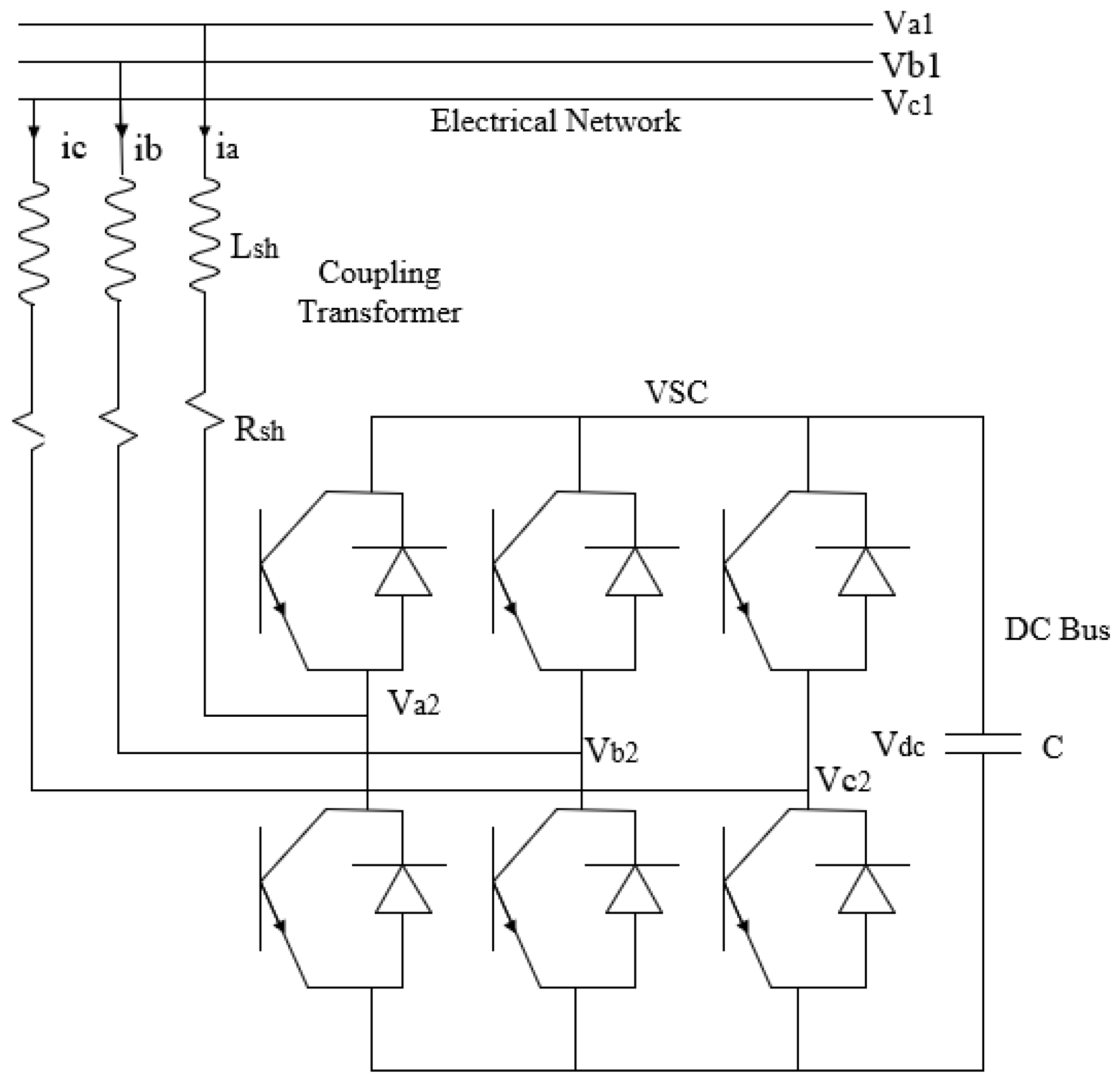
With the development of power electronics, particularly the GTO thyristor, the STATCOM, a reactive power compensation controller connected to the shunt, has become feasible. This technology has emerged as a viable alternative to the traditional SVC. Figure 1 shows the schematic layout of the STATCOM. The active and reactive powers (P) and (Q) of the transmission lines may be represented as [20]
where V1 and V2 are the system bus voltage and inverter output voltage, correspondingly, and X is the line reactance between the system bus and the inverter.
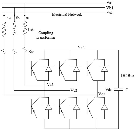
Figure 1.
Schematic layout of STATCOM.
Through the correlation between the AC voltage of the system and the AC shunt voltage of the STATCOM, reactive power flow control is feasible. The STATCOM functions as a capacitor and injects reactive power into the system when the voltage across the terminals of the STATCOM exceeds the system voltage. Conversely, when the STATCOM voltage is lower than the AC voltage, it functions as an inductor and reverses the reactive power flow. Under normal operating conditions, the system maintains balanced voltage levels, which prevents any current exchange between STATCOM and the network. Figure 2 demonstrates the STATCOM’s voltage and current characteristics. The resistance represents the active power losses in the winding of the coupling transformer winding and switches, while inductance represents the coupling transformer leakage reactance [27].
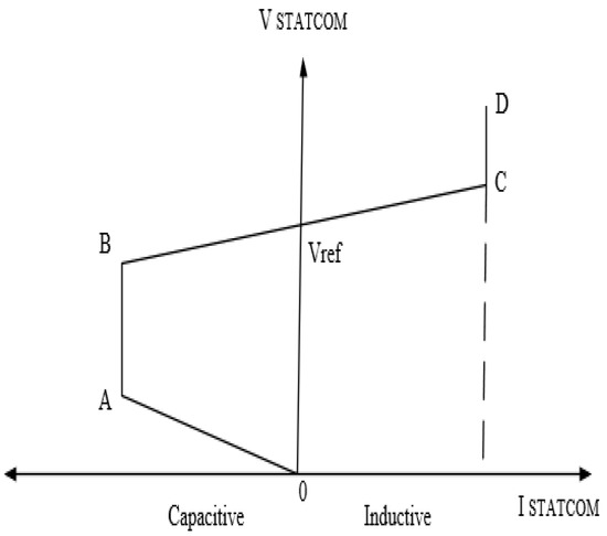
Figure 2.
STATCOM V-I characteristics.
The instantaneous network voltages and STATCOM voltage are not associated. However, the id and iq components propagate through the reactance of the coupling transformer.
The DC bus voltage is signified by
The DC current is calculated by
The voltage and current vectors are depicted in a park reference frame in Figure 3, while the phase shift angle and conversion ratio (m) can be calculated as
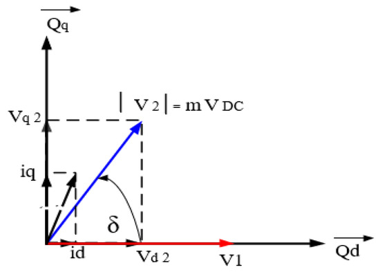
Figure 3.
Diagram depicting the voltage and current vectors of a STATCOM.
2.2. Fuzzy Logic Controller
The FLC is regarded as more efficient and advantageous than classical controllers such as the PI controller, PID controller, and others. It requires less storage capacity and is well-suited for nonlinear systems. It is crucial in various practical applications and offers numerous fuzzy inference mechanisms [28]. This study selected the Mamdani-type inference mechanism due to its computational efficiency and compactness.
Figure 4 displays the structure of the FLC system, comprising four major components. The components include fuzzification, fuzzy rule base, fuzzy inference engine, and defuzzification. Fuzzy logic comprises four key elements.
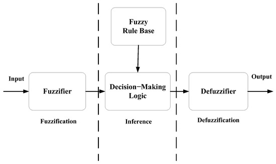
Figure 4.
The structure of FLC.
- A-
- Fuzzification (fuzzifier) is the process of converting a numerical value into a linguistic value or mapping the input space to a fuzzy set defined in the universe of discourse. This process entails converting the input data into linguistic values equivalent to the labels of the fuzzy sets.
- B-
- The knowledge base (fuzzy rule base) consists of a database and fuzzy rule base. The database contains definitions required for linguistic rules and fuzzy data processing. The rule base defines the objectives and strategies of experts using linguistic guiding rules.
- C-
- Decision-making logic (fuzzy inference engine) is the core of FLC. It can simulate human decision making based on vague concepts and infer fuzzy control functions using fuzzy implications and fuzzy logical inference rules.
- D-
- Defuzzification (defuzzifier) implements the following functions: scale mapping, which converts the output variables’ values into consistent discourse universes, and defuzzification, which produces the non-fuzzy control functions from the derived control functions.
Mamdani Method: It is implemented in this study and is computationally efficient and more compact. The system has two inputs, X1 and X2, and a single output, Y. The system’s error and the change in error are represented as X1 and X2, respectively. Output Y is represented by a fuzzy output [29].
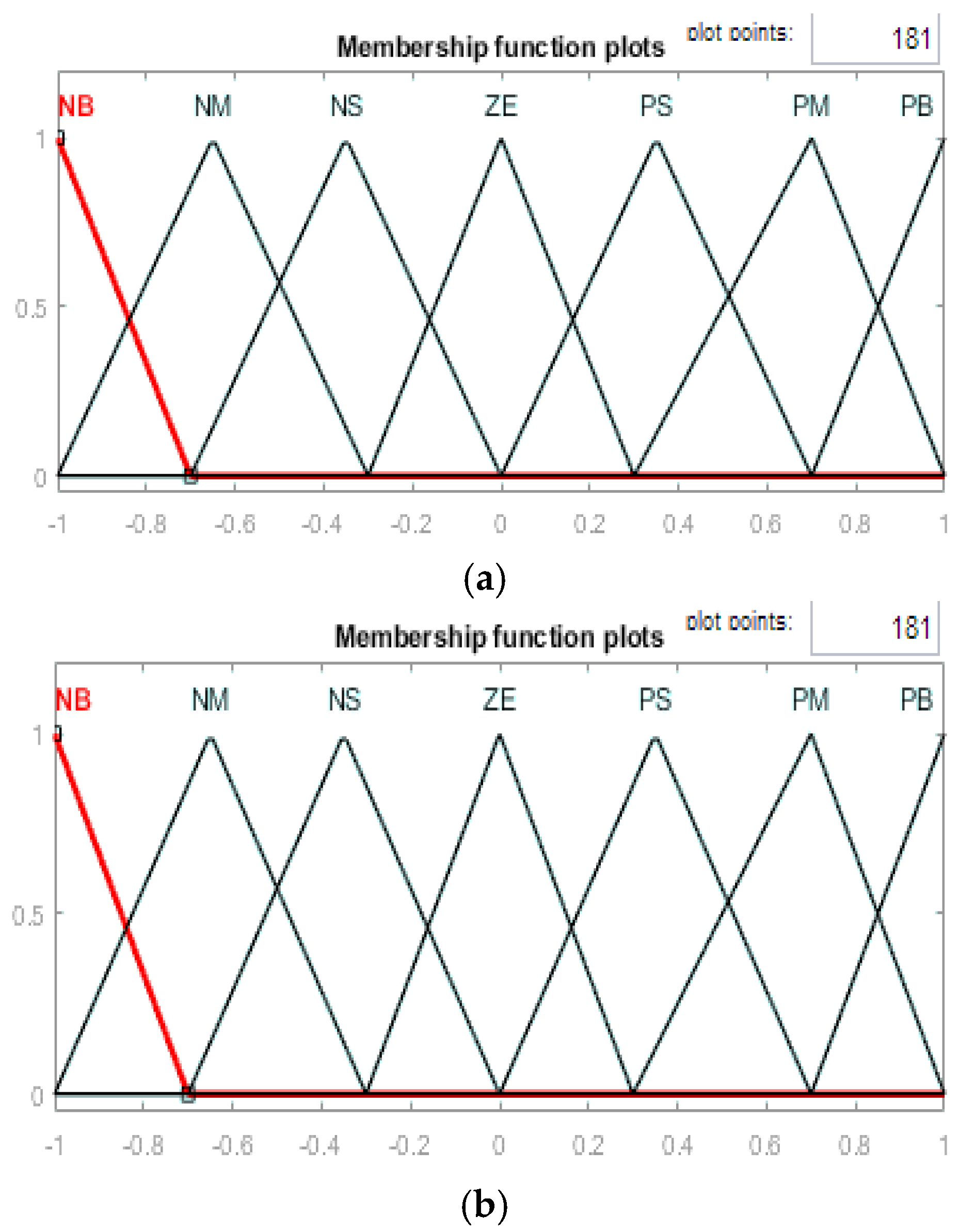
The FLC converts a linguistic control strategy into an automated design, with fuzzy rules generated by either an expert or a knowledge database. Seven fuzzy levels or sets (membership functions) were selected to provide a numerical characterization of each fuzzy logic state for improved outcomes: NB (negative big), NM (negative medium), NS (negative small), ZE (zero), PS (positive small), PM (positive medium), and PB (positive big), as shown in Figure 5.
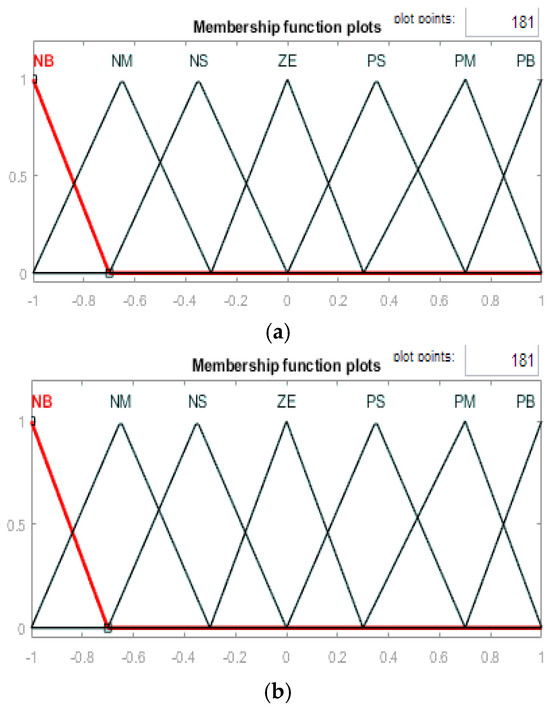
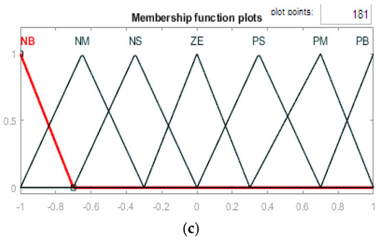
Figure 5.
Membership functions of the fuzzy controller. (a) The error (X1). (b) The change in error (X2). (c) The output (Y).
According to fuzzy set theory, large transient errors require coarse control with coarse input/output variables, whereas small steady-state errors require finetuning with fictitious input/output variables. The rule-based elements are determined based on this concept, as shown in Table 1, where E represents the error, and ∆E represents the change in error. Figure 6 displays the flowchart of the FLC, in which all its steps are described.

Table 1.
The ruleset of a fuzzy controller.
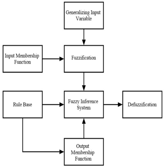
Figure 6.
Flowchart of FLC system.
2.3. STATCOM Coordinated Supercapacitor
A capacitor is utilized in the STATCOM to supply the DC voltage required for the voltage source converter (VSC). Energy storage systems can achieve the dual objectives of supplying DC voltage and real power while enhancing the stability margins, as their power conversion systems resemble the VSCs utilized in FACTS devices. Various electrical energy storage systems include supercapacitors, superconducting magnetic energy storage devices, flywheel storage devices, and battery energy storage systems. Supercapacitors notably integrate the advantages of electrochemical batteries and conventional capacitors, devoid of the chemical reactions that may constrain cycle capacity. They are distinctive electrical storage devices that provide superior power density compared to batteries and can retain considerably more energy than conventional capacitors. Compared to alternative energy storage technologies, supercapacitors enhance the dynamic compensation capabilities of conventional STATCOM systems [7].
2.4. Adaptive Neuro-Fuzzy Inference System
Neuro-fuzzy systems represent a novel class of intelligent systems that integrate the essential characteristics of FLC and ANN. It is widely recognized that neither fuzzy systems nor neural networks can effectively address problems that require linguistic and numerical knowledge simultaneously. An ANFIS is a fuzzy system employing an ANN learning approach to determine parameters, including fuzzy sets and rules, by analyzing data examples [30].
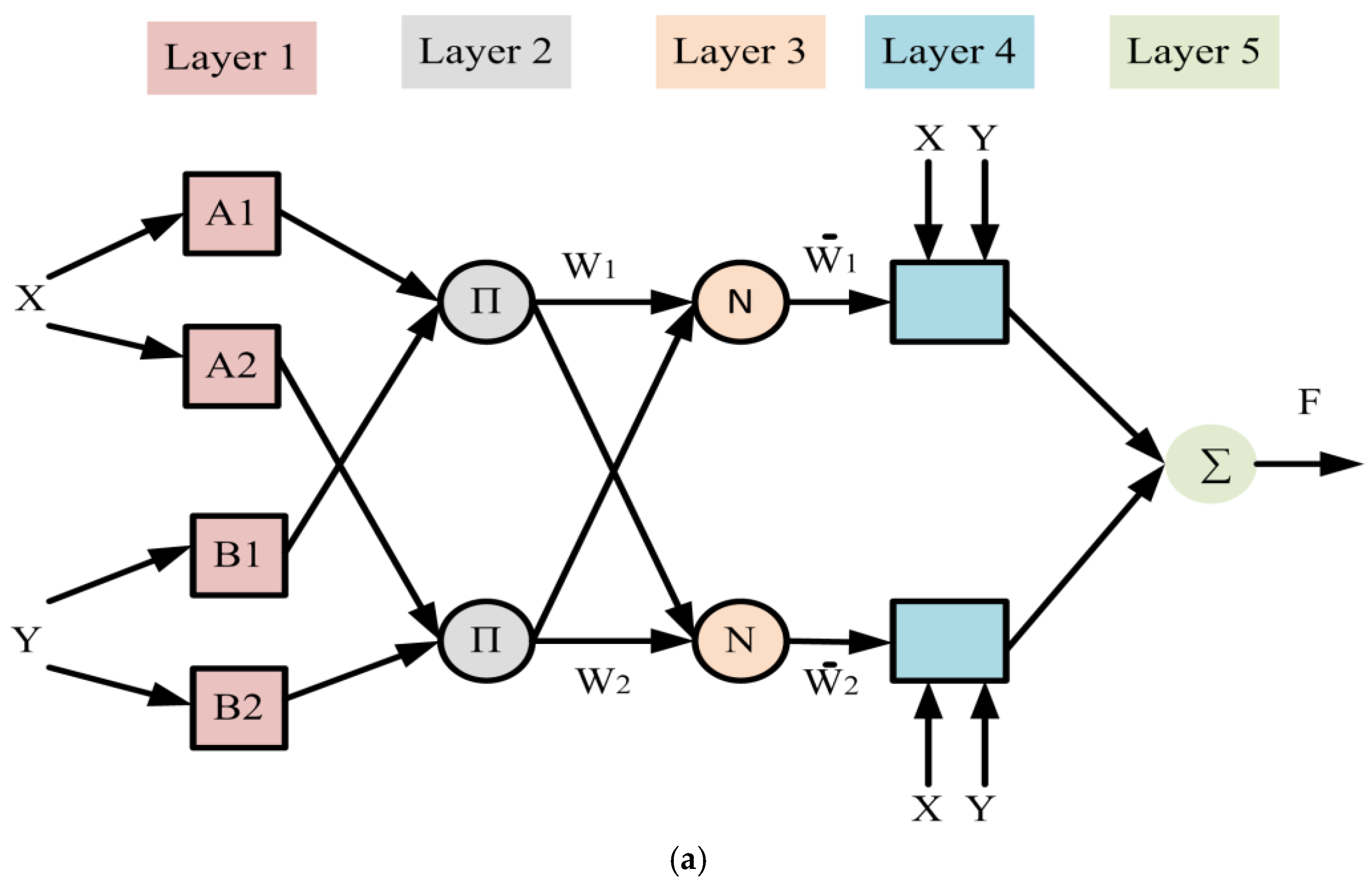
The ANFIS algorithm is structured with five distinct layers, each comprising nodes that utilize the Sugeno fuzzy model. The Sugeno fuzzy model is highly applicable due to its superior computational efficiency, interpretability, integrated optimization capabilities, and adaptive techniques. The layers are interconnected through directed connections, allowing each node to perform specific operations on incoming signals to generate a single output. The primary objective of ANFIS is to determine the optimal values for the parameters of the corresponding fuzzy inference system by employing a learning algorithm. The nodes within the layers can be classified into adaptive nodes (represented by square symbols) and fixed nodes (represented by circular symbols). A comprehensive illustration of the ANFIS architecture is presented in (Figure 7a).

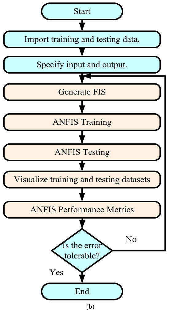
Figure 7.
Implementation of the ANFIS controller. (a) The basic architecture of the ANFIS algorithm. (b) Flowchart of ANFIS implementation.
In each model, the common rule set consists of two fuzzy if–then rules for two inputs, X, Y, and one output, F, which can be described as follows:
Rule 1: if X is A1 and Y is B1, then F1 = p1 + q1 + r1.
Rule 2: if X is A2 and Y is B2, then F2 = p2 + q2 + r2.
The variables A1, A2, B1, and B2 represent nonlinear parameters, while Ai and Bi denote fuzzy membership functions. p1, q1, p2, q2, and r1, r2 are linear parameters that function as design parameters established during the training process. The layers of the ANFIS procedure can be summarized as follows:
Layer 1 (fuzzifying layer): In this layer, each input node i operates as an adaptive node that produces a membership grade for the linguistic label. This represents a fuzzy layer wherein X and Y function as inputs to the system, Ai and Bi are labeled (e.g., small, large), and μ(X) may be any parameterized membership function. The output of the ith node in layer 1 is represented as O1,i defined as follows:
Layer 2 (implication layer): The neurons are categorized п and represented by a circle. An AND operator is employed in this layer to fuzzify the inputs. The output generated by this layer, , represents the firing strength of the rules. The output of this layer can be signified using Equation (9):
Layer 3 (normalizing layer): Each neuron in this layer is a designated fixed neuron, represented by a circle and labeled as N. The output is determined by the ratio of the firing strength of the ith rule to the total firing strength across all rules. The fixed node could normalize the firing strength received from the second layer. The output of this layer can be signified using Equation (10):
Layer 4 (defuzzifying layer): This layer comprises adaptive neurons that incorporate consequence parameters. The adaptive node calculates the product of first-order Sugeno polynomials using the normalized firing strengths derived from the previous layer. The output of this layer is represented by Equation (11):
where , , and are the parameter set of this node, referred to as consequent parameters.
Layer 5 (combining layer): This layer consists of a single neuron labeled Σ, represented by a circle that calculates the overall output by aggregating all incoming signals. The output of this layer can be signified using Equation (12):
Figure 7 also shows the flowchart of the ANFIS control system in which all steps of ANFIS are designated.
2.5. System Stability
Stability in a control system refers to its ability to maintain the desired output without deviation or oscillation. System stability pertains to the condition where every bounded input results in an unbounded output [31].
Voltage instability is characterized by fluctuations, sags, and surges in voltage levels. These include abrupt fluctuations in line voltage and current amplitude in relation to the reference voltage level. These issues commonly arise in power systems due to sudden changes, including three-phase faults and dynamic load variations.
The evaluation of a STATCOM’s dynamic performance requires an assessment of its ability to provide a rapid response following a transient event. This is achieved by injecting reactive power to improve the power system stability. The response time denotes the interval necessary to identify a suitable solution. The performance is deemed satisfactory when the response is both rapid and accurate, while it is regarded as unsatisfactory when it is slow or incorrect.
The stability analysis of ANFIS and FLC controllers in a STATCOM system can be validated using various methodologies. These methodologies provide unique perspectives on system performance across different conditions. Time-domain analysis evaluates transient and steady-state responses to disturbances, offering insights into the system’s behavior over time. Eigenvalue analysis assesses stability by confirming that all eigenvalues have negative real parts, thereby ensuring the absence of unstable modes. The Lyapunov stability criterion provides an extra verification method by examining the system’s behavior via a defined function with a non-positive derivative. Frequency-domain methods, including the Bode and Nyquist criteria, assess gain and phase margins, helping to identify stability in the frequency spectrum. Root locus analysis examines the movement of poles to confirm that the system maintains a well-damped response.
Time-domain analysis is applied to evaluate the dynamic performance of ANFIS and FLC controllers in a STATCOM-based system. This approach entails the application of disturbances, including three-phase faults and load variations, to analyze the system’s transient and steady-state responses. Key performance indicators encompass the voltage deviation, settling time, and overshoot, which assess the system’s capacity to sustain stability amid varying conditions. The effectiveness of AN-FIS and FLC controllers in mitigating voltage fluctuations and enhancing power system stability can be assessed by comparing their response characteristics. A controller exhibiting a reduced settling time, lower overshoot, and minimal voltage deviation is preferred for improved dynamic stability.
3. System Under Study
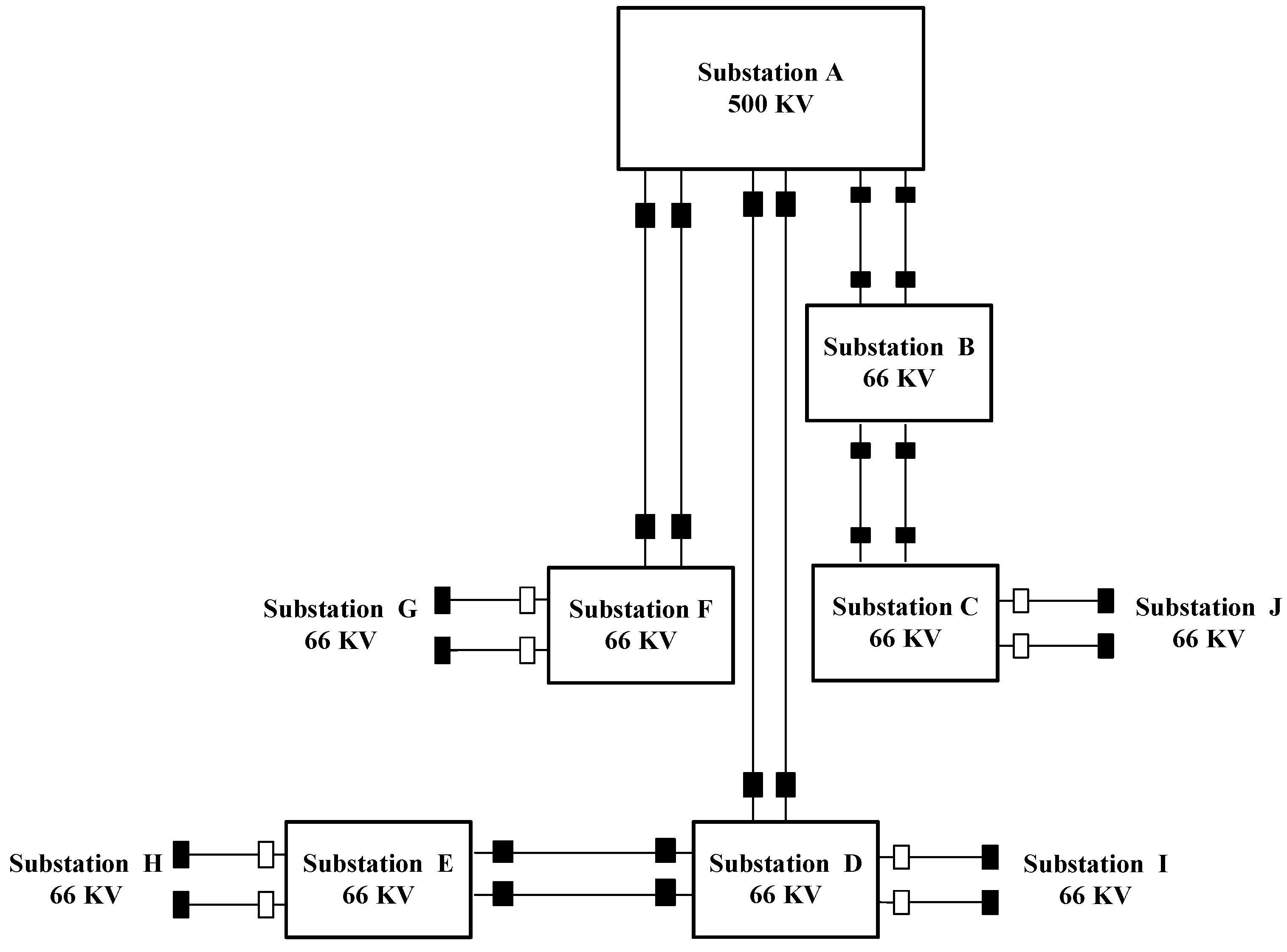
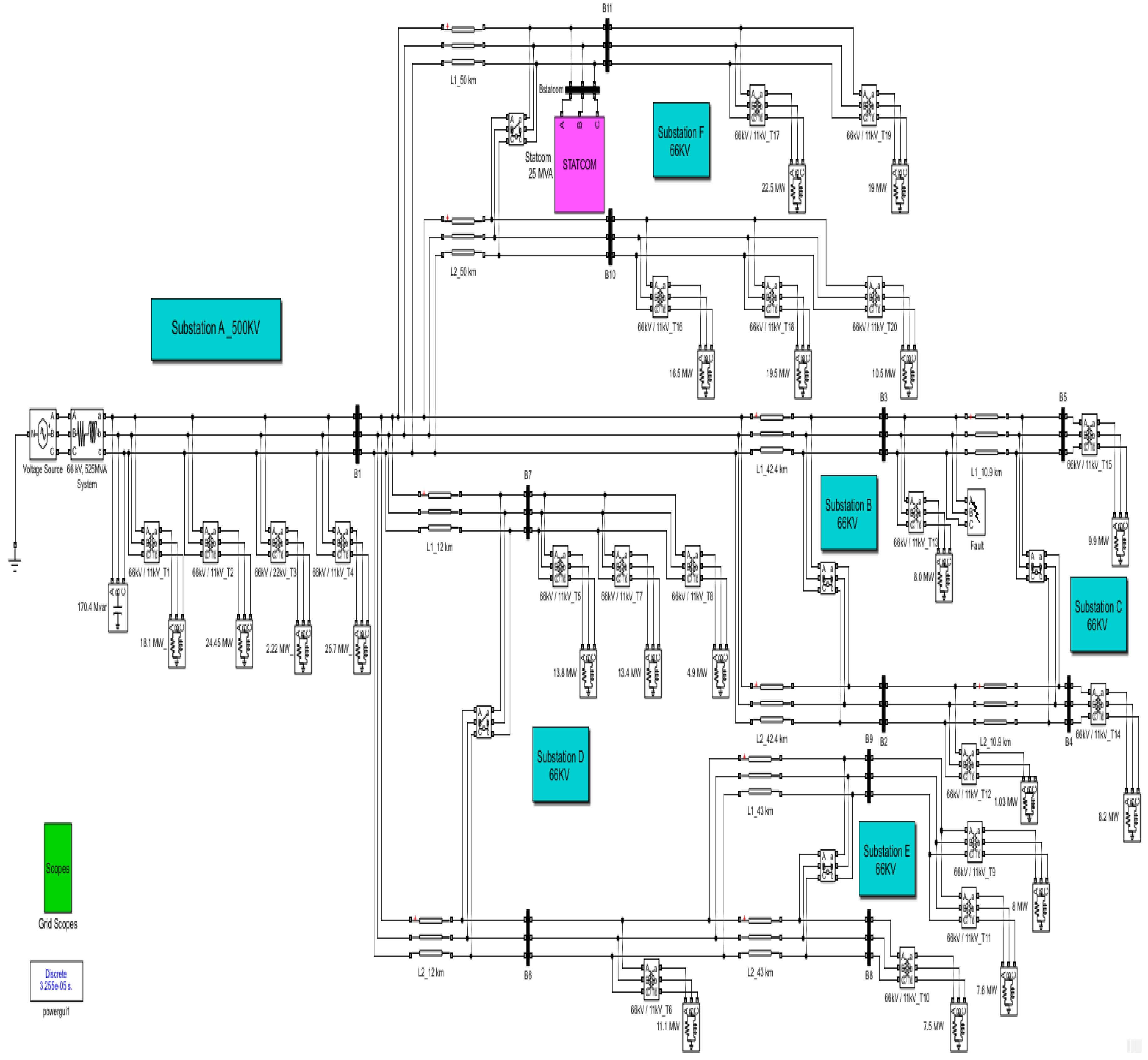
Figure 8 presents a block diagram demonstrating the electrical power transmission substations within the Middle Egypt Electricity Zone under study. Figure 9 shows the Simulink model of the electrical transmission network operating at 66 KV and 525 MVA. The apparent power of the system is 525 MVA, with the load apparent power limited to a maximum of 85% of its rated capacity, equating to 446.25 MVA, to ensure the safe operation of the power transformers and prevent system overload.
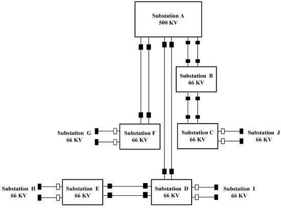
Figure 8.
The block diagram of electrical power transmission stations in the Middle Egypt Electricity Zone under study.
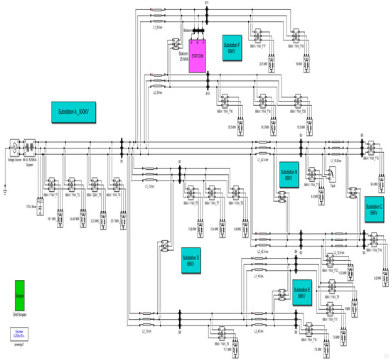
Figure 9.
The proposed model of the electrical transmission network in MATLAB/Simulink.
The system integrates STATCOM with a fuzzy logic controller. The evaluation was conducted under multiple abnormal conditions. The system comprises electrical power transmission substations located in the Middle Egypt Electricity Zone, such as substation A (500 KV), which is considered the main substation of the proposed system, substation B (66 KV), substation C (66KV), substation D (66 kV), substation E (66 KV), and substation F (66 KV). All the 66 KV transmission substations are supplied from substation A (500 KV transmission substation). The STATCOM of 25-MVA and 66 KV was connected to the shunt at bus B11. The power system voltage was adjusted to (±10%) of the nominal value utilizing a three-phase variable voltage source in accordance with the simulation timeline, as presented in Table 2. Table 3 lists the data parameters of the system, and STATCOM in the model under study.
Table 2.
The voltage source variation.
Table 3.
The data of the system and STATCOM.
The performance of the electrical power network with STATCOM, including two controller types, was offered and checked under different fault conditions. The possible cases for research are as follows:
- ▪
- Case 1: The electrical network at normal operation without STATCOM, with STATCOM-PI controller, with STATCOM-FLC, with STATCOM-FLC coordinated supercapacitor, and with STATCOM-ANFIS controller.
- ▪
- Case 2: The electrical network under voltage variation without STATCOM, with STATCOM-PI controller, with STATCOM-FLC, with STATCOM-FLC coordinated supercapacitor, and with STATCOM-ANFIS controller.
- ▪
- Case 3: The electrical network under voltage reduction without STATCOM, with STATCOM-FLC, with STATCOM-FLC coordinated supercapacitor, and with STATCOM-ANFIS controller.
- ▪
- Case 4: The electrical network under a single line-to-ground fault was inserted near bus B3 without STATCOM, with STATCOM-FLC, with STATCOM-FLC coordinated supercapacitor, and with STATCOM-ANFIS controller.
- ▪
- Case 5: The electrical network under a three-line-to-ground fault was inserted near bus B3 without STATCOM, with STATCOM-FLC, with STATCOM-FLC coordinated supercapacitor, and with STATCOM-ANFIS controller.
- ▪
- Case 6: The electrical network using two STATCOM units coordinated with the ANFIS controller under normal operating conditions was inserted near bus B3 under a three-line-to-ground fault.
4. Simulation Results
The system was analyzed under both normal operation and abnormal conditions utilizing the MATLAB/Simulink software package. The findings indicated that the performance of the power system can be markedly enhanced using STATCOM-FLC, surpassing the effectiveness of the PI controller. The integration of STATCOM-FLC with supercapacitors demonstrated superior performance compared to STATCOM-FLC alone, with optimal results achieved when STATCOM was paired with the ANFIS controller.
This simulation exhibited a short-circuit fault with multiple fault types occurring between t = 0.2 and 0.21 s under abnormal conditions. The fault was introduced near bus B3, and the grid voltages and currents were simulated across all cases utilizing the MATLAB/Simulink software package. Integrating a STATCOM device with an ANFIS controller enhanced the system performance during normal operation and fault conditions.
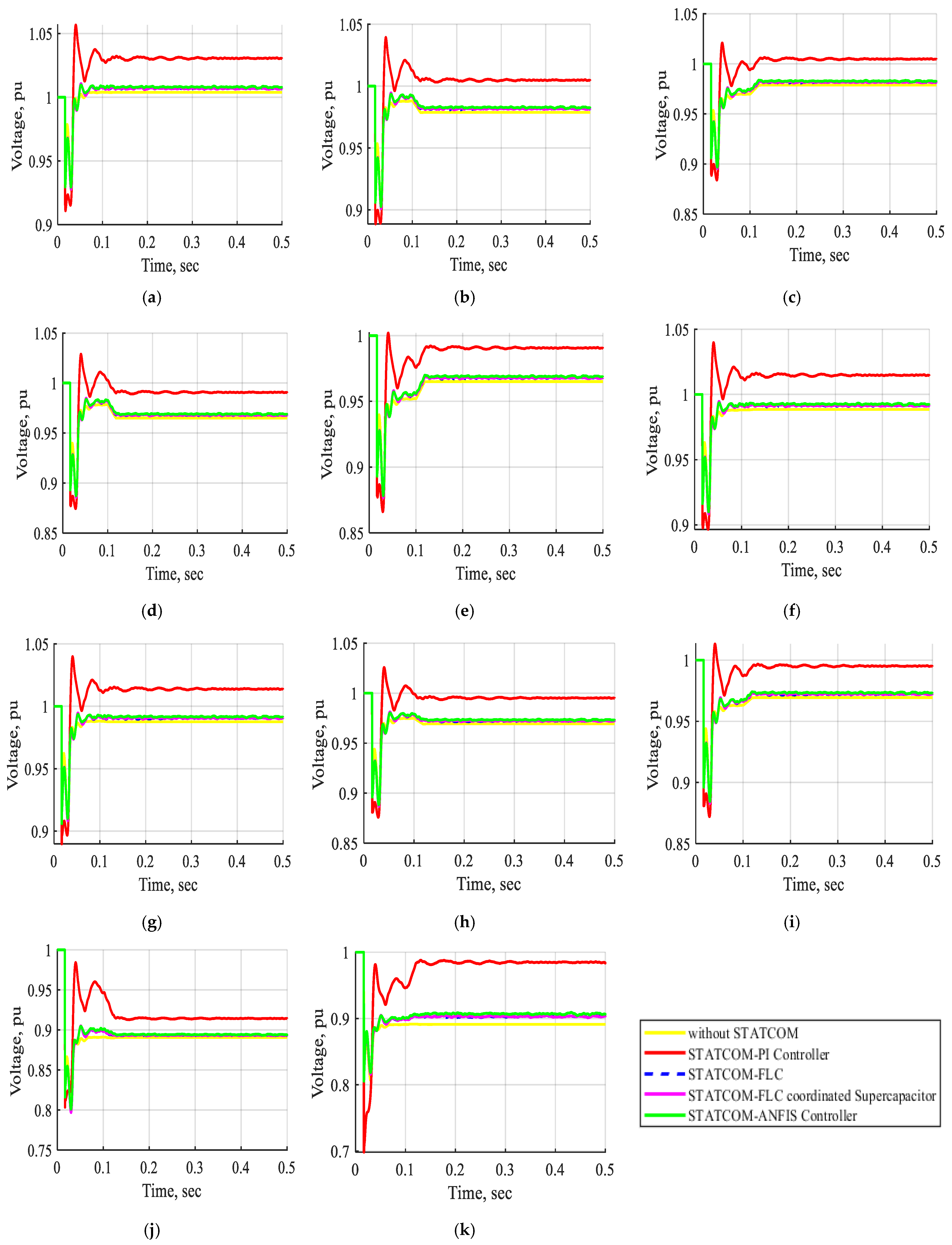
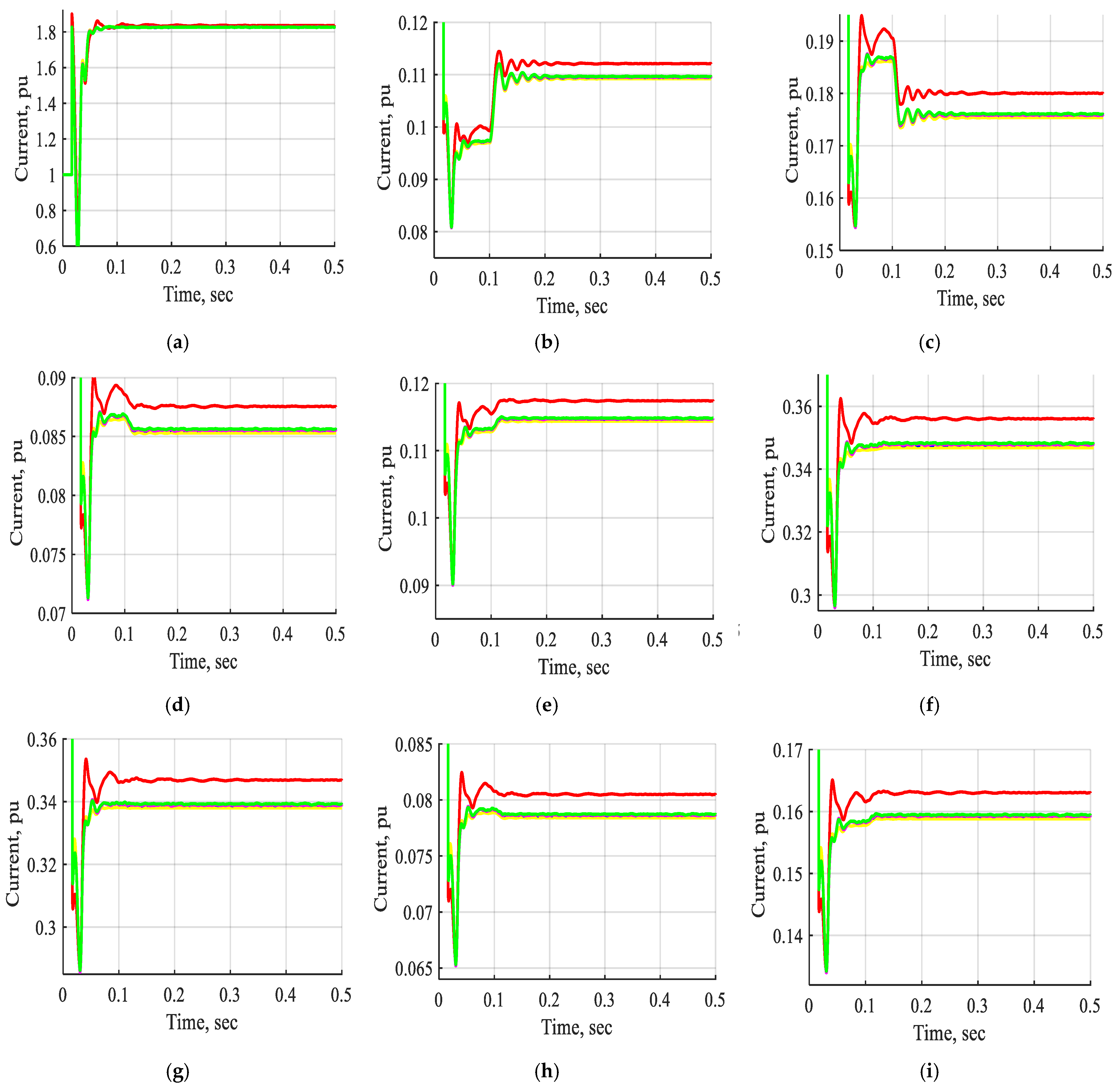
The yellow solid line represents the performance in the absence of the STATCOM across all study cases. The performance of the STATCOM utilizing the PI controller is represented by a red solid line, whereas the dashed blue line denotes the performance of the STATCOM-FLC, and the solid magenta line illustrates the performance of the STATCOM-FLC coordinated supercapacitor. The solid green line indicates the performance of the one-unit STATCOM-ANFIS controller, while the solid pink line denotes the performance of the two-unit configuration.
Case 1:
The electrical network operates under normal conditions without STATCOM, with STATCOM-PI controller, with STATCOM-FLC, with STATCOM-FLC coordinated supercapacitor, and with STATCOM-ANFIS controller.
Table 4 depicts a comparison between the measured and simulated voltages in system buses B1 to B11. It is noted that the percentage difference between the measured and simulated values of the system voltage buses ranges between 0.12 and 2.00 percent.
Table 4.
Comparison between the measured voltage and the simulated voltage.
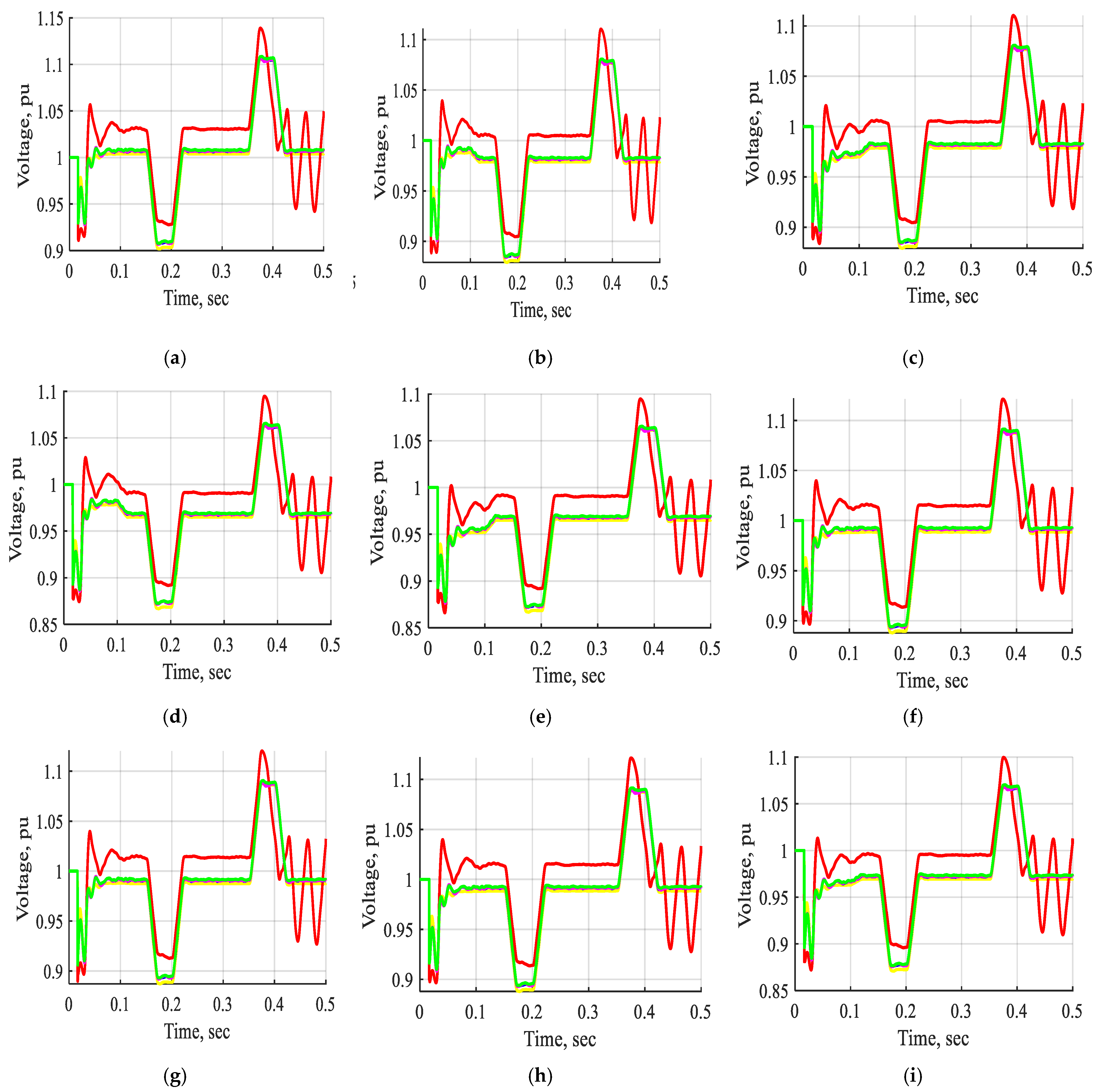
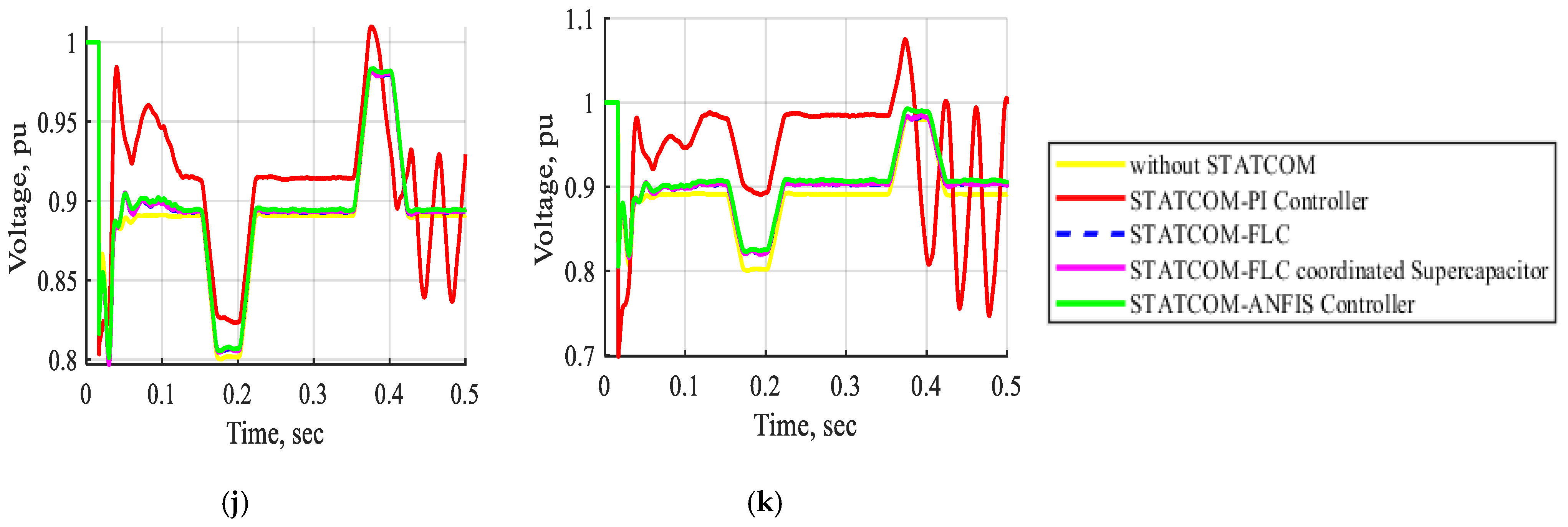
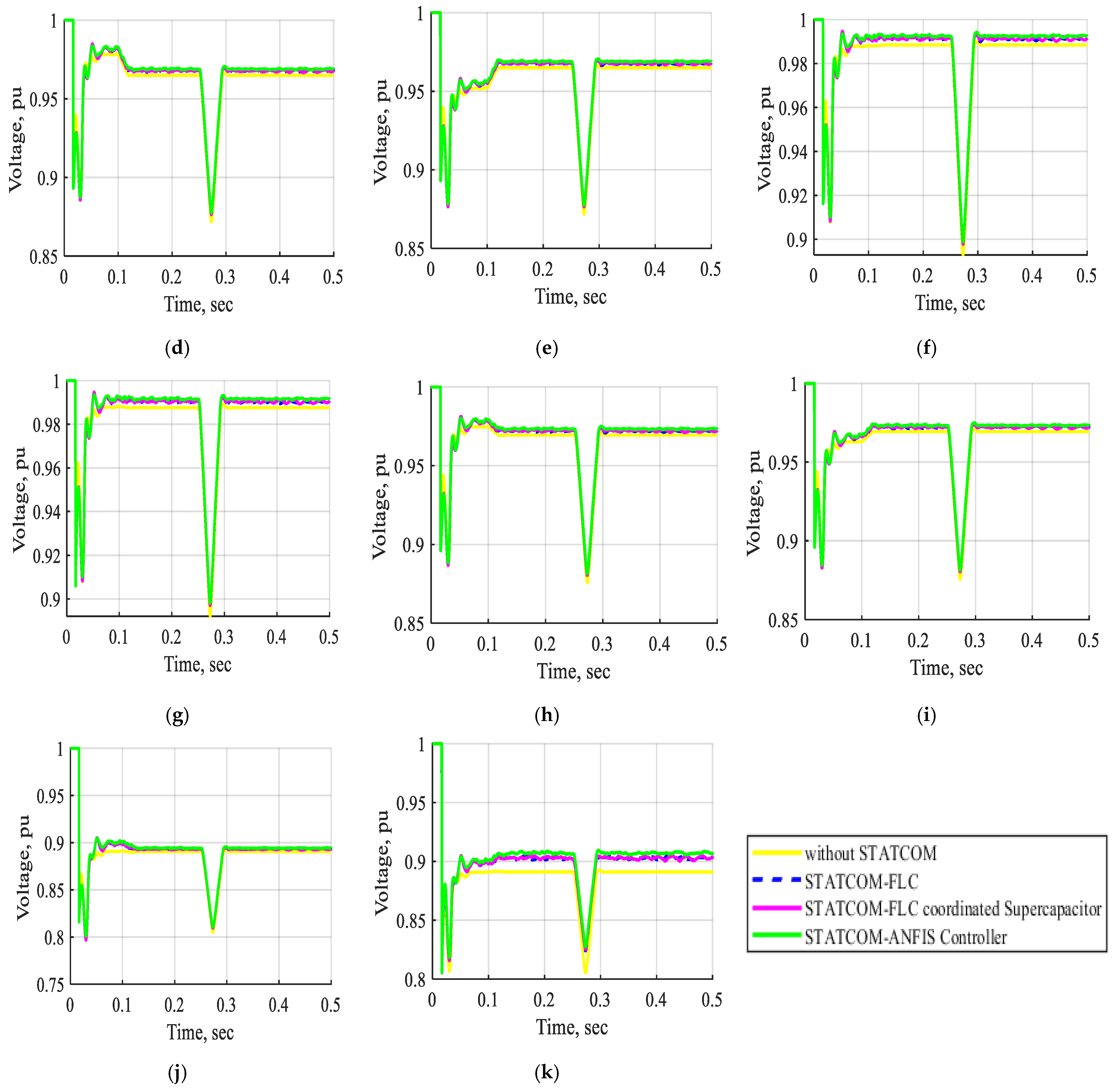
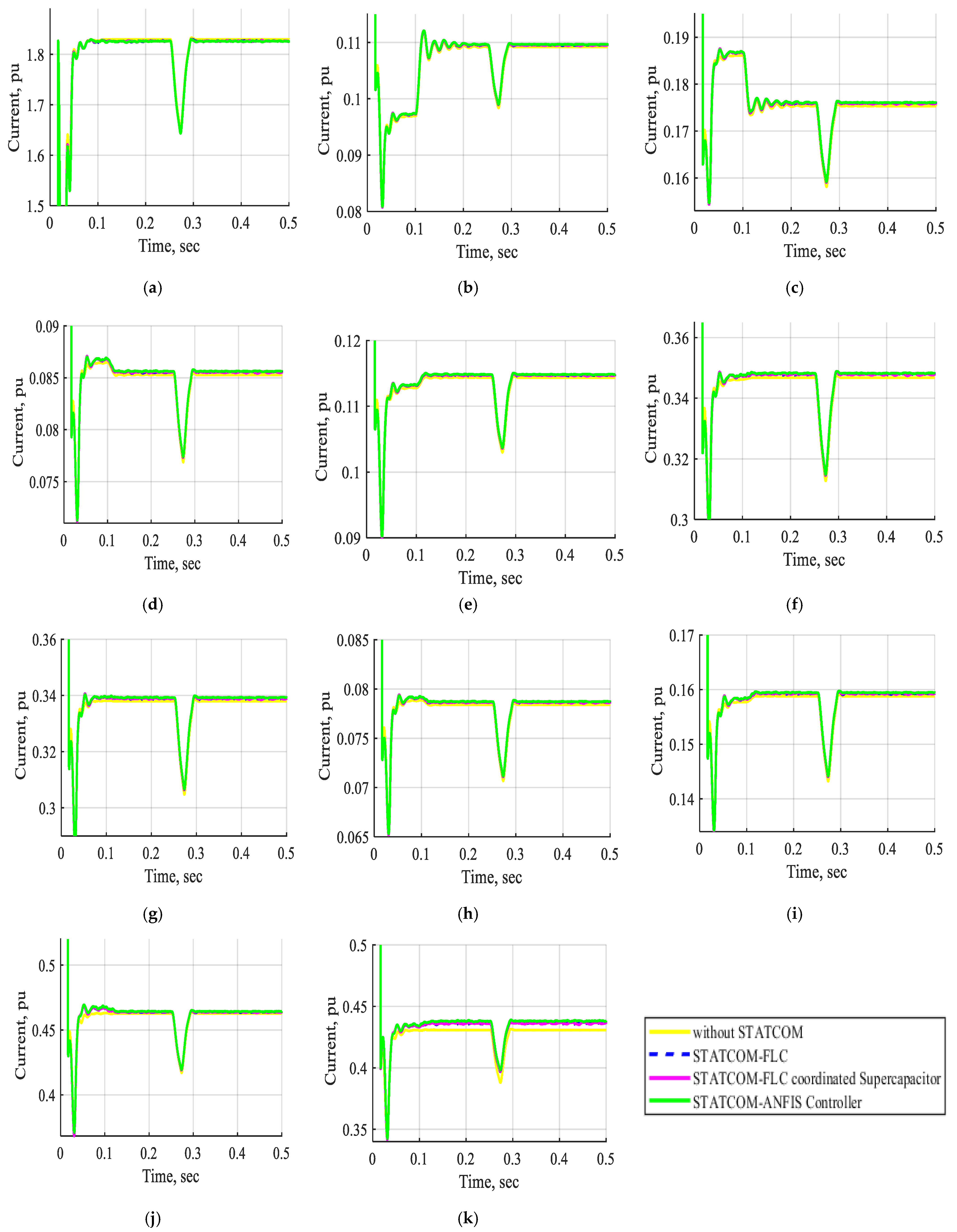
Figure 10 and Figure 11 show the voltage and current waveforms of bus B1 to bus B11 under various conditions: without STATCOM, with STATCOM-PI controller, with STATCOM-FLC, with STATCOM-FLC coordinated supercapacitor, and with STATCOM-ANFIS controller during normal operation. The data indicate that the voltage and current waveforms from bus B1 to bus B11 during normal operation with the STATCOM utilizing the PI controller show significant improvement compared to those without the STATCOM. The system exhibits improved performance with the STATCOM-PI controller; however, it experiences oscillations in the resulting waveforms. The implementation of a STATCOM utilizing a fuzzy controller results in significantly enhanced voltage and current profiles compared to a STATCOM employing a PI controller. Additionally, the fuzzy logic controller demonstrates reduced oscillations in the waveforms relative to the PI controller. The STATCOM integrated with the FLC-coordinated supercapacitor demonstrates superior performance compared to the traditional FLC. The system’s optimal performance is achieved with STATCOM utilizing an ANFIS controller, outperforming all other controllers. Integrating STATCOM with an ANFIS controller improves the system’s performance during normal operation, particularly in terms of oscillations and steady-state response, surpassing the effectiveness of PI and fuzzy controllers, thereby contributing to enhanced system stability.
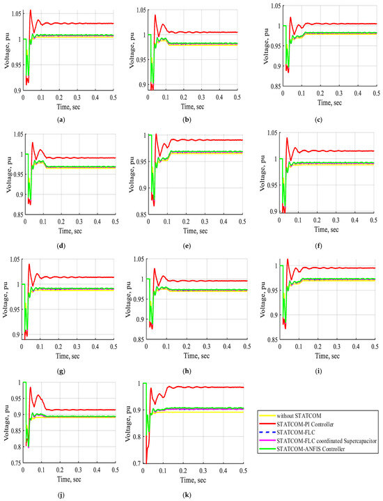
Figure 10.
The voltage waveform of buses B1, B2, B3, B4, B5, B6, B7, B8, B9, B10, and B11 in pu without STATCOM, with STATCOM-PI controller, with STATCOM-FLC, with STATCOM-FLC coordinated supercapacitor and STATCOM-ANFIS controller at normal operation. (a) The voltage waveform of bus B1 in pu. (b) The voltage waveform of bus B2 in pu. (c) The voltage waveform of bus B3 in pu. (d) The voltage waveform of bus B4 in pu. (e) The voltage waveform of bus B5 in pu. (f) The voltage waveform of bus B6 in pu. (g) The voltage waveform of bus B7 in pu. (h) The voltage waveform of bus B8 in pu. (i) The voltage waveform of bus B9 in pu. (j) The voltage waveform of bus B10 in pu. (k) The voltage waveform of bus B11 in pu.
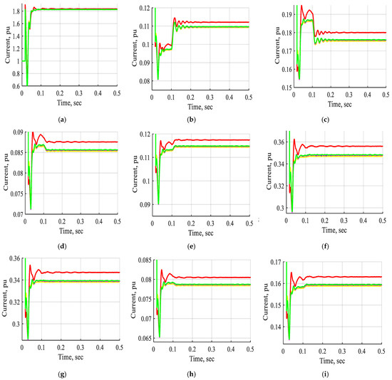
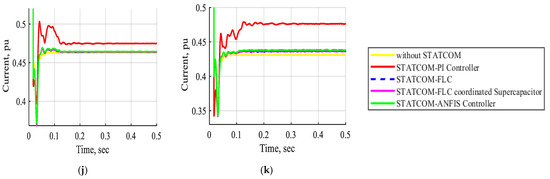
Figure 11.
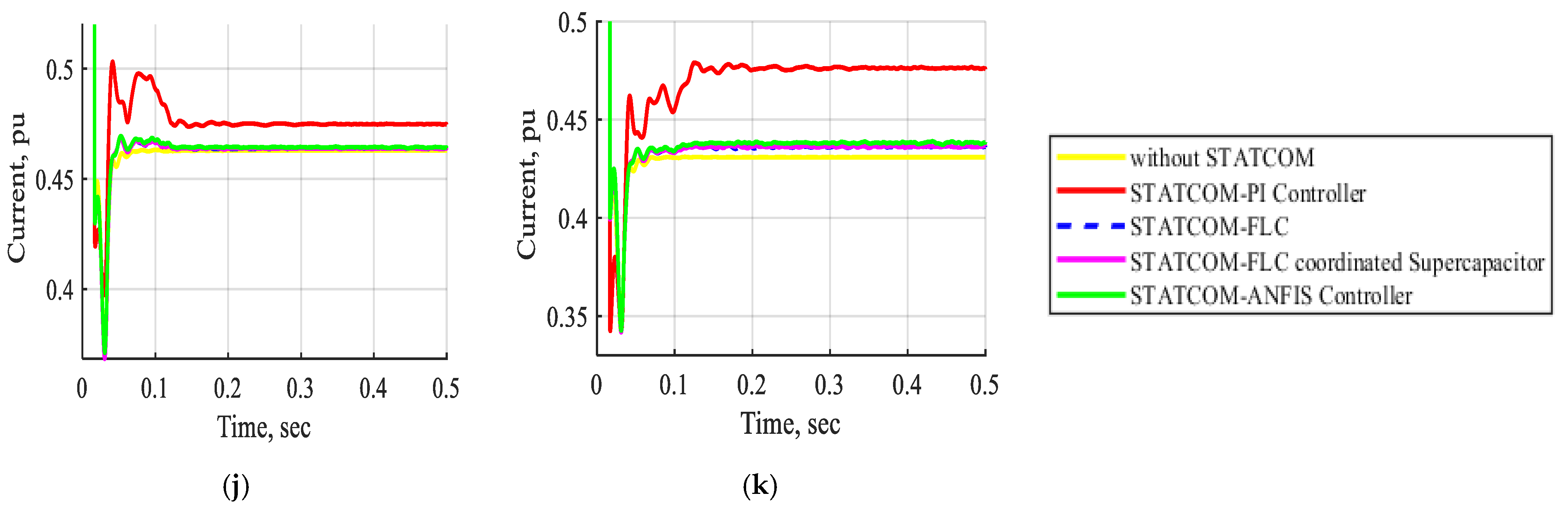
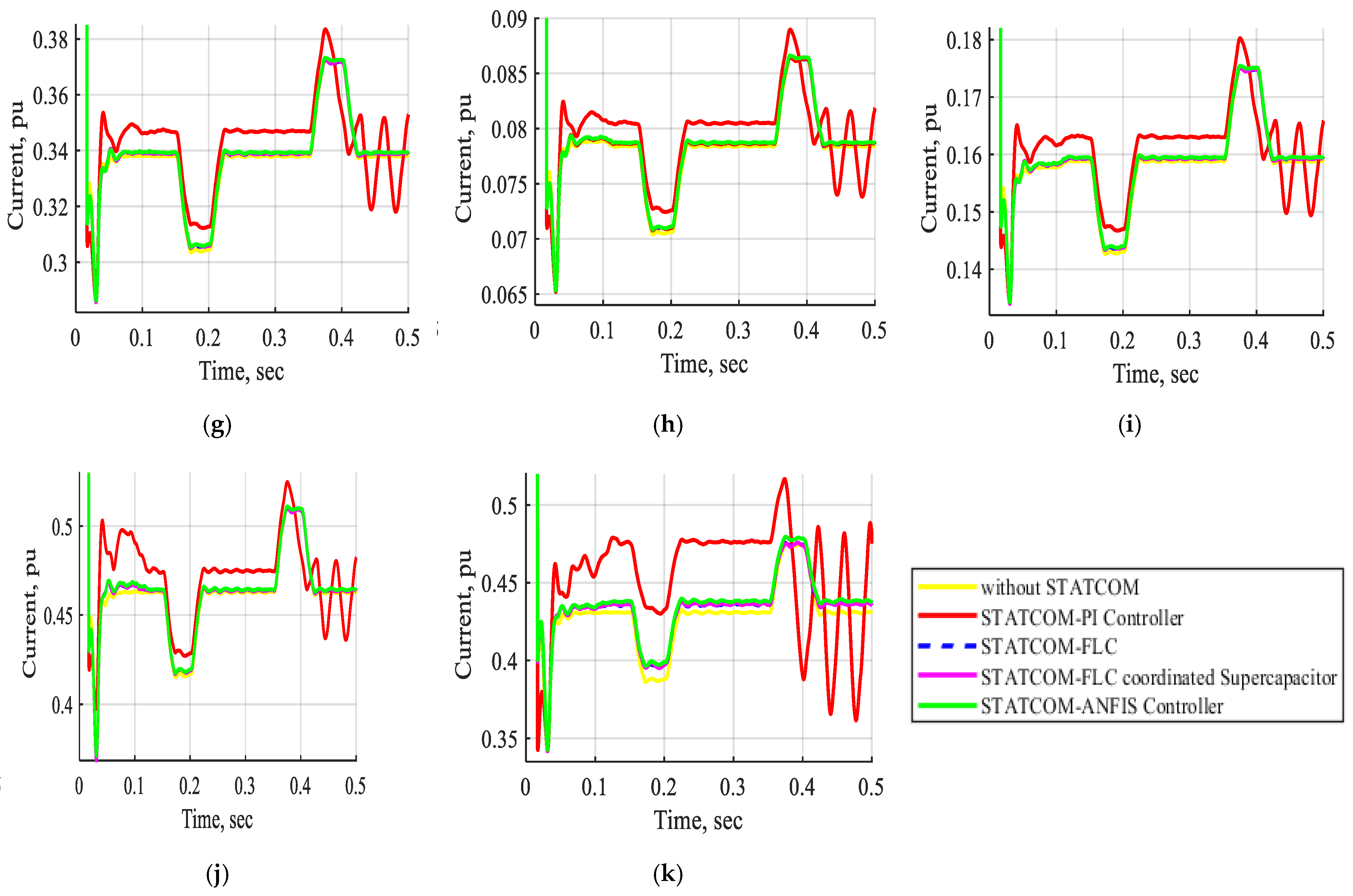
The current waveform of buses B1, B2, B3, B4, B5, B6, B7, B8, B9, B10, and B11 in pu without STATCOM, with STATCOM-PI controller, with STATCOM-FLC, with STATCOM-FLC coordinated supercapacitor and STATCOM-ANFIS controller at normal operation. (a) The current waveform of bus B1 in pu. (b) The current waveform of bus B2 in pu. (c) The current waveform of bus B3 in pu. (d) The current waveform of bus B4 in pu. (e) The current waveform of bus B5 in pu. (f) The current waveform of bus B6 in pu. (g) The current waveform of bus B7 in pu. (h) The current waveform of bus B8 in pu. (i) The current waveform of bus B9 in pu. (j) The current waveform of bus B10 in pu. (k) The current waveform of bus B11 in pu.
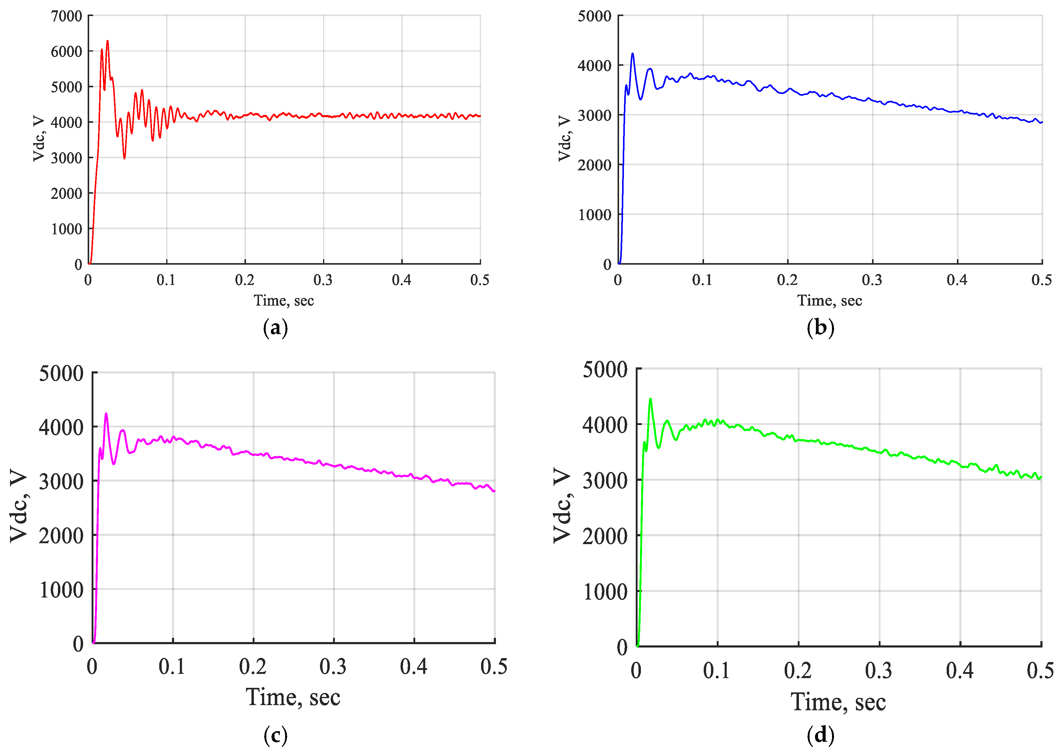
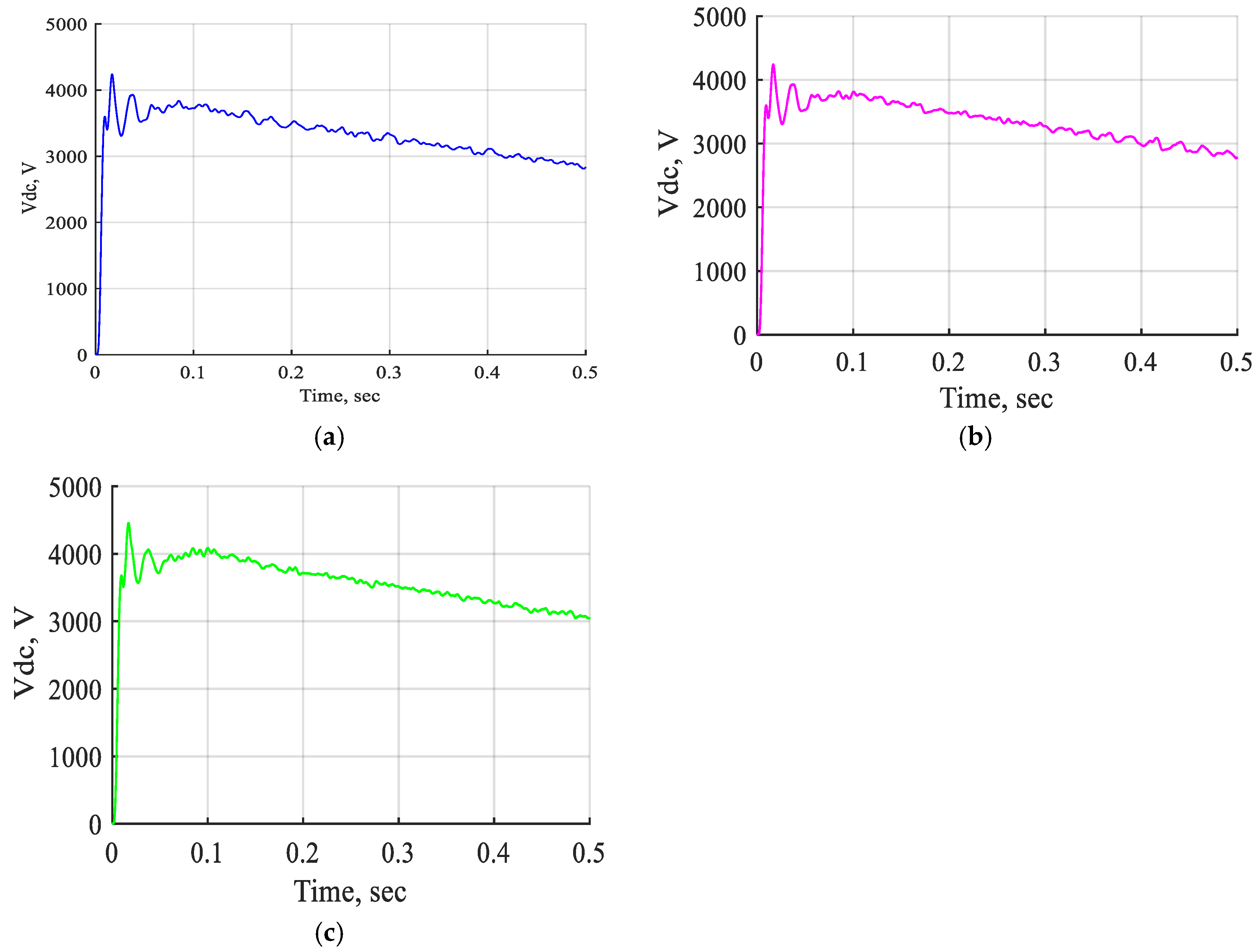
Figure 12 demonstrates the performance of the DC voltage across the STATCOM-PI controller, STATCOM-FLC, STATCOM-FLC-coordinated supercapacitor, and STATCOM-ANFIS controller under normal operating conditions. The simulation reveals fluctuations in the DC voltage waveform when employing the STATCOM-PI controller; however, the implementation of FLC and ANFIS controllers results in reduced fluctuation in the DC voltage in the same period.
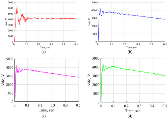
Figure 12.
The DC voltage wave shapes of STATCOM-PI controller, STATCOM-FLC, STATCOM-FLC coordinated supercapacitor, and STATCOM-ANFIS controller at normal operation. (a) The DC voltage wave shape of STAT-COM-PI controller. (b) The DC voltage wave shape of STAT-COM-FLC. (c) The DC voltage wave shape of STATCOM-FLC coordinated supercapacitor. (d) The DC voltage wave shape of the STATCOM-ANFIS controller.
Table 5 shows the effect of the STATCOM device with different controllers in system buses voltage in pu at normal operation. The implementation of a STATCOM with diverse controllers improves the voltage levels at the buses during standard operation. The STATCOM with a PI controller demonstrates the highest voltage values relative to other controllers; however, the voltage waveforms are suboptimal and display oscillations. The comparison of voltages at buses B10 and B11, both with and without the device under normal operational conditions, demonstrates that the STATCOM significantly enhances the bus voltages. The voltage increased to 100.382% and 101.953%, respectively, compared to their values without the STATCOM when employing the ANFIS controller. The voltage increased to (100.3144, 101.246%) using an FLC and (100.326, 101.392%) with an FLC coordinated supercapacitor. Consequently, the ANFIS controller yields the most favorable results in comparison to the others.
Table 5.
Effect of STATCOM with different controllers in system buses’ voltage in pu during normal operation.
Case 2:
The electrical network under voltage variation without STATCOM, with STATCOM-PI controller, with STATCOM-FLC, with STATCOM-FLC coordinated supercapacitor, and with STATCOM-ANFIS controller.
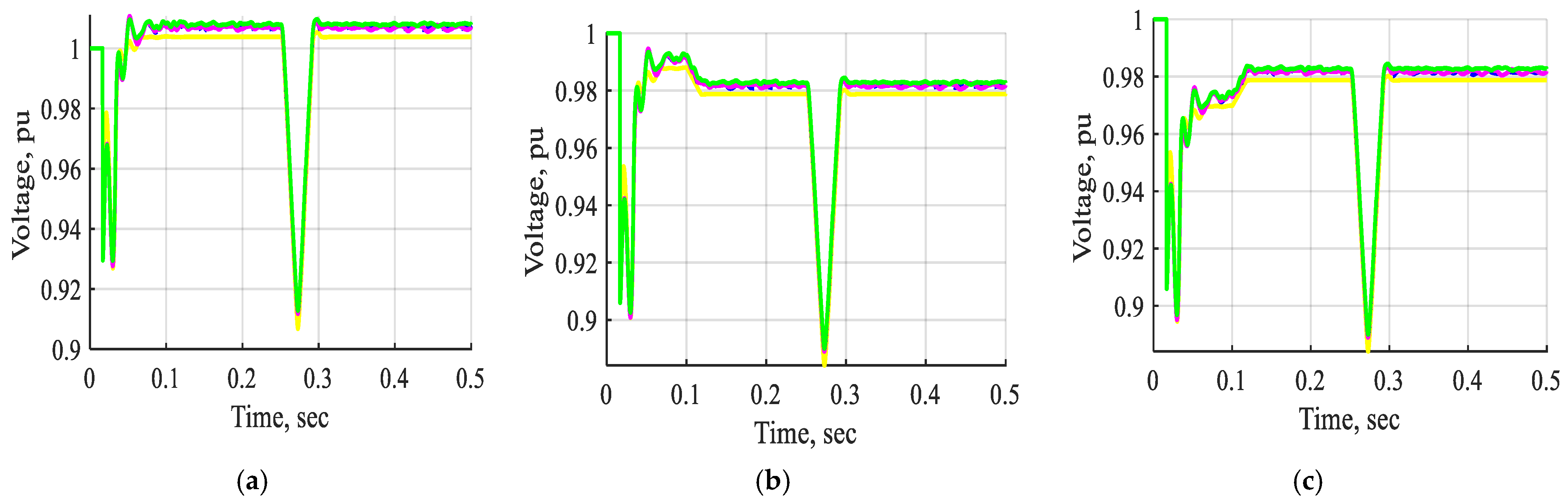
Figure 13 and Figure 14 show the voltage and current waveforms of bus B1 to bus B11 without STATCOM, with STATCOM-PI controller, with STATCOM-FLC, with STATCOM-FLC coordinated supercapacitor, and with STATCOM-ANFIS controller under voltage variation. The waveforms demonstrate that the voltage and current vary significantly with alterations in the voltage source. The results indicate that the voltage and current waveforms from bus B1 to bus B11 are significantly enhanced when implementing the STATCOM with a PI controller, compared to scenarios without the STATCOM. The system demonstrates improved performance with the STATCOM-PI controller; however, it experiences oscillations in the resulting waveforms. The implementation of STATCOM utilizing fuzzy and ANFIS controllers significantly enhances the voltage and current profiles compared to those achieved with a PI controller. Additionally, using FLCs and ANFIS controllers reduces oscillations in the waveforms relative to the PI controller. The STATCOM adjusts the power system voltage by varying it within ±10% of its nominal value. The use of a STATCOM based on FLC enhances the system stability under varying voltage sources compared to the PI controller or the absence of STATCOM devices. Additionally, the incorporation of a supercapacitor contributes to improved performance relative to conventional FLC. Conversely, the system operates most effectively with the ANFIS controller. The previous results demonstrated that the STATCOM equipped with the ANFIS controller enhanced the overall system stability by mitigating oscillations through the application of FLCs and the ANFIS controller during normal operation and under voltage source variation.
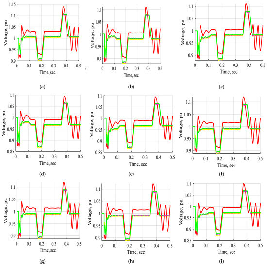
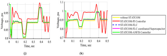
Figure 13.
The current waveform of buses B1, B2, B3, B4, B5, B6, B7, B8, B9, B10, and B11 in pu without STATCOM, with STATCOM-PI controller, with STATCOM-FLC, with STATCOM-FLC coordinated supercapacitor, and STATCOM-ANFIS controller under voltage variation. (a) The voltage waveform of bus B1 in pu. (b) The voltage waveform of bus B2 in pu. (c) The voltage waveform of bus B3 in pu. (d) The voltage waveform of bus B4 in pu. (e) The voltage waveform of bus B5 in pu. (f) The voltage waveform of bus B6 in pu. (g) The voltage waveform of bus B7 in pu. (h) The voltage waveform of bus B8 in pu. (i) The voltage waveform of bus B9 in pu. (j) The voltage waveform of bus B10 in pu. (k) The voltage waveform of bus B11 in pu.
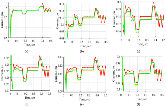
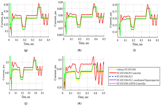
Figure 14.
The current waveform of buses B1, B2, B3, B4, B5, B6, B7, B8, B9, B10, and B11 in pu without STATCOM, with STATCOM-PI controller, with STATCOM-FLC, with STATCOM-FLC coordinated supercapacitor, and STATCOM-ANFIS controller under voltage variation. (a) The current waveform of bus B1 in pu. (b) The current waveform of bus B2 in pu. (c) The current waveform of bus B3 in pu. (d) The current waveform of bus B4 in pu. (e) The current waveform of bus B5 in pu. (f) The current waveform of bus B6 in pu. (g) The current waveform of bus B7 in pu. (h) The current waveform of bus B8 in pu. (i) The current waveform of bus B9 in pu. (j) The current waveform of bus B10 in pu. (k) The current waveform of bus B11 in pu.
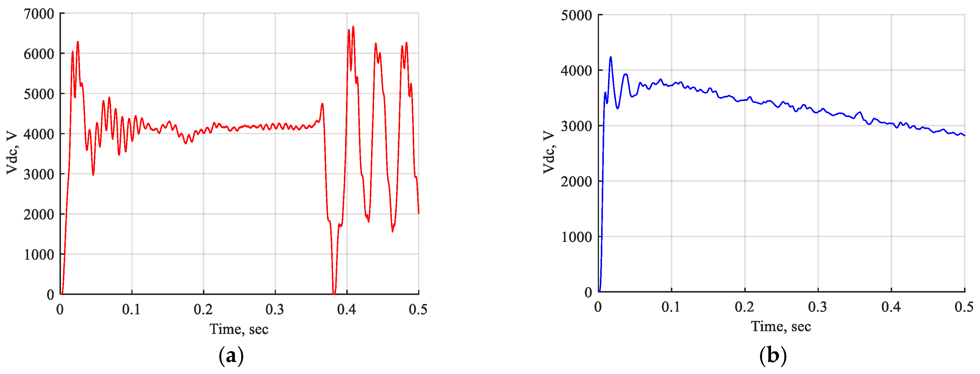
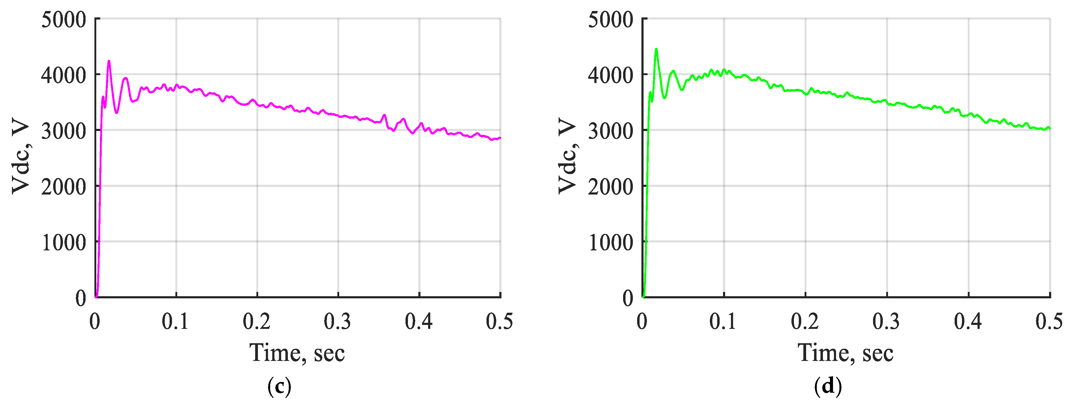
Figure 15 shows the DC voltage behavior of the STATCOM-PI controller, STATCOM-FLC, STATCOM-FLC-coordinated supercapacitor, and STATCOM-ANFIS controller under varying voltage sources. The DC voltage waveform exhibits considerable changes with oscillations between t = 0 s and 0.5 s when utilizing the STATCOM-PI controller. In contrast, the implementation of STATCOM with fuzzy and ANFIS controllers results in reduced fluctuation in the DC voltage in the same period.
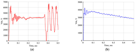
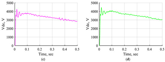
Figure 15.
DC voltage waveforms of the STATCOM-PI controller, STATCOM-FLC, STATCOM-FLC coordinated with a supercapacitor, and STATCOM-ANFIS controller under conditions of voltage variation. (a) The DC voltage wave shape of STAT-COM-PI controller. (b) The DC voltage wave shape of STAT-COM-FLC. (c) The DC voltage wave shape of STATCOM-FLC coordinated supercapacitor. (d) The DC voltage wave shape of STAT-COM-ANFIS controller.
Case 3:
The electrical network under voltage reduction without STATCOM, with STATCOM-FLC, with STATCOM-FLC coordinated supercapacitor, and with STATCOM-ANFIS controller.
Figure 16 and Figure 17 show the voltage and current waveforms of bus B1 to bus B11 without STATCOM, with STATCOM-FLC, with STATCOM-FLC coordinated supercapacitor, and with STATCOM-ANFIS controller under decreasing the voltage source in the period from t = 0.15 s to 0.2 s. The waveforms demonstrate that both the voltage and current exhibit considerable variation with a decrease in the voltage source. The STATCOM can regulate the power system voltage by adjusting it by up to -10% from its nominal value. The system’s performance in the absence of the STATCOM is significantly inadequate and necessitates an extended duration to achieve stability. The implementation of STATCOM with FLC leads to improved system performance. The system exhibits improved performance with STATCOM-FLC; however, it is prone to oscillations in the resulting waveforms. Implementing the STATCOM-FLC coordinated supercapacitor significantly enhances the voltage and current profiles compared to the conventional STATCOM-FLC, exhibiting reduced oscillations in the waveforms. Furthermore, the performance is notably superior when utilizing the STATCOM-ANFIS controller. The implementation of the STATCOM-ANFIS controller improves the system stability during normal operation and under reduced voltage conditions, compared to STATCOM based on FLCs or not using the STATCOM device.
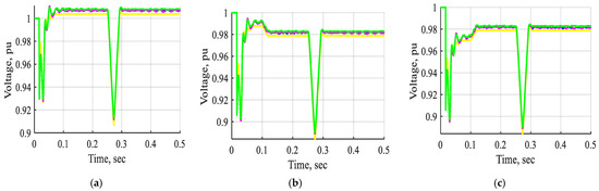
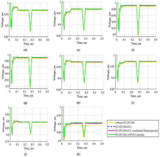
Figure 16.
The voltage waveform of buses B1, B2, B3, B4, B5, B6, B7, B8, B9, B10, and B11 in pu without STATCOM, without STATCOM, with STATCOM-FLC, with STATCOM-FLC coordinated supercapacitor, and with STATCOM-ANFIS controller under decreasing the voltage source. (a) The voltage waveform of bus B1 in pu. (b) The voltage waveform of bus B2 in pu. (c) The voltage waveform of bus B3 in pu. (d) The voltage waveform of bus B4 in pu. (e) The voltage waveform of bus B5 in pu. (f) The voltage waveform of bus B6 in pu. (g) The voltage waveform of bus B7 in pu. (h) The voltage waveform of bus B8 in pu. (i) The voltage waveform of bus B9 in pu. (j) The voltage waveform of bus B10 in pu. (k) The voltage waveform of bus B11 in pu.
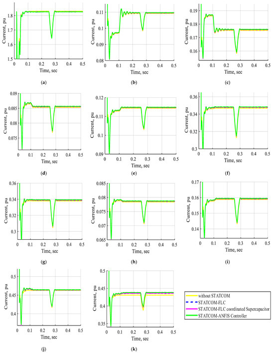
Figure 17.
The current waveform of buses B1, B2, B3, B4, B5, B6, B7, B8, B9, B10, and B11 in pu without STATCOM, without STATCOM, with STATCOM-FLC, with STATCOM-FLC coordinated supercapacitor, and with STATCOM-ANFIS controller under decreasing the voltage source. (a) The current waveform of bus B1 in pu. (b) The current waveform of bus B2 in pu. (c) The current waveform of bus B3 in pu. (d) The current waveform of bus B4 in pu. (e) The current waveform of bus B5 in pu. (f) The current waveform of bus B6 in pu. (g) The current waveform of bus B7 in pu. (h) The current waveform of bus B8 in pu. (i) The current waveform of bus B9 in pu. (j) The current waveform of bus B10 in pu. (k) The current waveform of bus B11 in pu.
Figure 18 shows the behavior of the DC voltage for STATCOM-FLC, STATCOM-FLC coordinated supercapacitor, and STATCOM-ANFIS controller during the voltage source reduction from t = 0.15 s to 0.2 s. The implementation of the STATCOM with the ANFIS controller results in an improved DC voltage waveform, demonstrating superior system performance compared to fuzzy controllers.
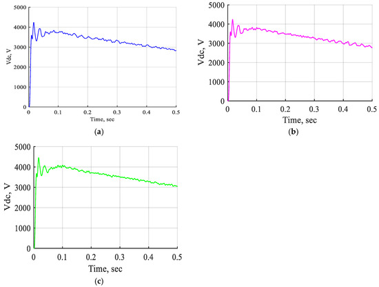
Figure 18.
The DC voltage wave shapes of STATCOM-FLC, STATCOM-FLC coordinated supercapacitor, and STATCOM-ANFIS controller under decreasing the voltage source. (a) The DC voltage wave shape of STAT-COM-FLC. (b) The DC voltage wave shape of STAT-COM-FLC coordinated supercapacitor. (c) The DC voltage wave shape of STATCOM- ANFIS controller.
Case 4:
The electrical network under a single line-to-ground fault was inserted near bus B3 without STATCOM, with STATCOM-FLC, with STATCOM-FLC coordinated supercapacitor, and with STATCOM-ANFIS controller.
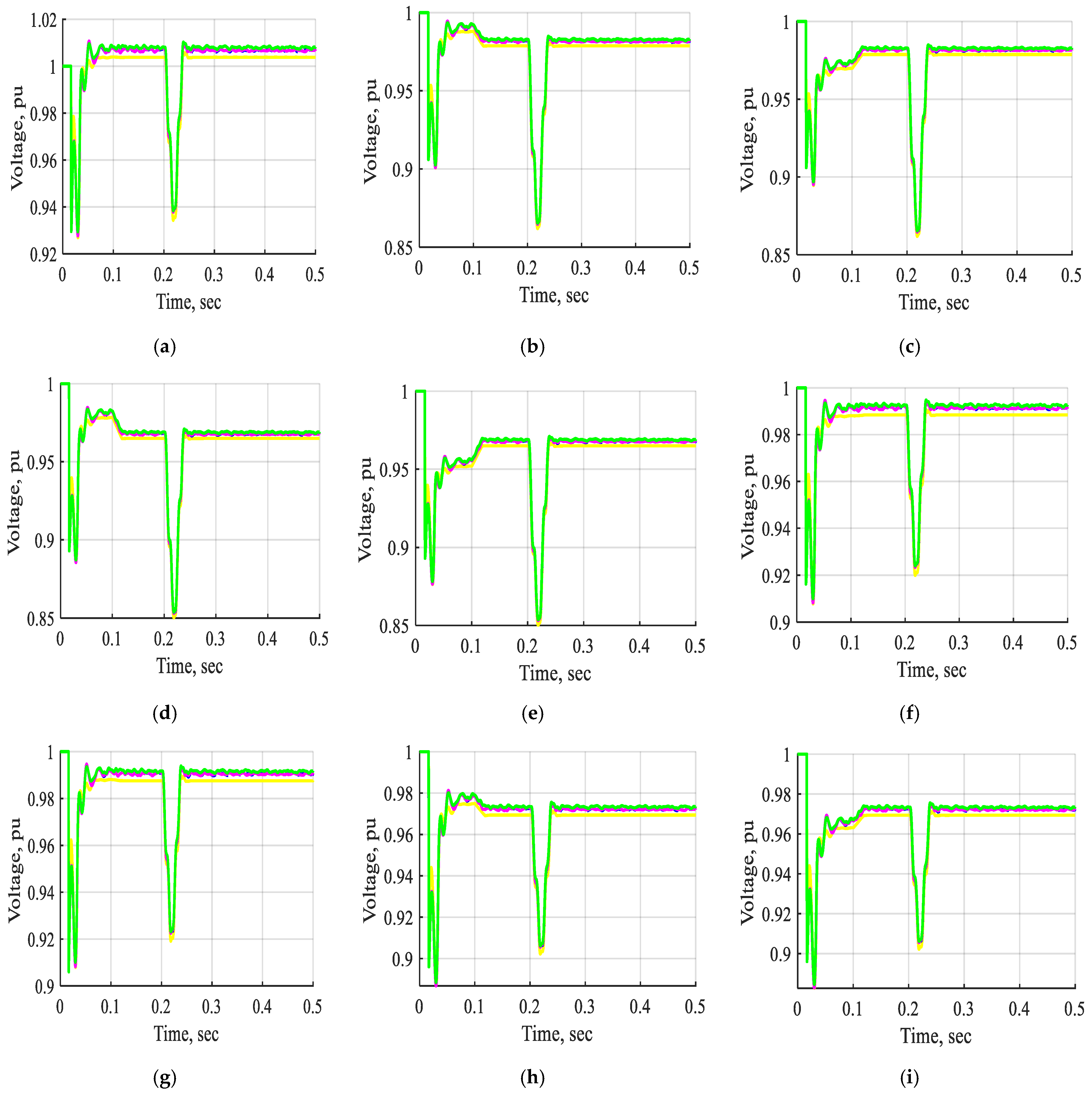
Figure 19 and Figure 20 show the voltage and current waveforms of bus B1 to bus B11 without STATCOM, with STATCOM-FLC, with STATCOM-FLC coordinated supercapacitor, and with STATCOM-ANFIS controller under a single line-to-ground fault inserted near bus B3. The waveforms indicated significant changes in the voltage and current during the interval from t = 0.2 s to 0.21 s, corresponding to a single line-to-ground fault near bus B3. Furthermore, the system lacking the STATCOM device needed an extended duration to achieve stabilization following a fault clearance. The STATCOM-FLC and STATCOM with supercapacitor exhibited quicker stabilization times, albeit with some oscillations in the resulting waveforms. In contrast, the STATCOM with the ANFIS controller demonstrated superior performance. The system’s performance during a single line-to-ground fault enhanced the overall bus voltages and currents due to the integration of the proposed STATCOM-ANFIS controller. Consequently, the stability of the system during a single line-to-ground fault was enhanced through the implementation of a STATCOM utilizing an ANFIS controller.
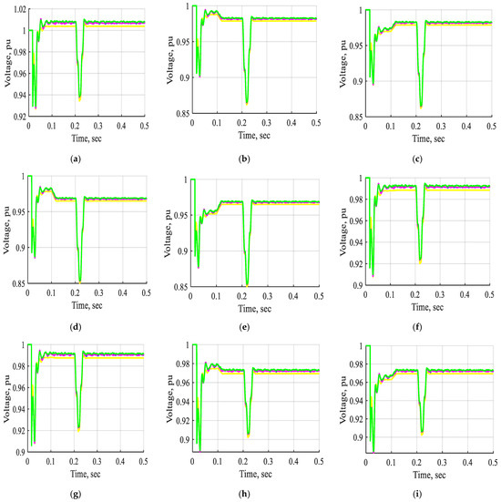
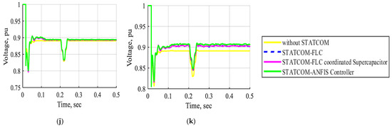
Figure 19.
The voltage waveform of buses B1, B2, B3, B4, B5, B6, B7, B8, B9, B10, and B11 in pu without STATCOM, without STATCOM, with STATCOM-FLC, with STATCOM-FLC coordinated supercapacitor, and with STATCOM-ANFIS controller for single line-to-ground fault near bus B3 at t = (0.2–0.21) s. (a) The voltage waveform of bus B1 in pu. (b) The voltage waveform of bus B2 in pu. (c) The voltage waveform of bus B3 in pu. (d) The voltage waveform of bus B4 in pu. (e) The voltage waveform of bus B5 in pu. (f) The voltage waveform of bus B6 in pu. (g) The voltage waveform of bus B7 in pu. (h) The voltage waveform of bus B8 in pu. (i) The voltage waveform of bus B9 in pu. (j) The voltage waveform of bus B10 in pu. (k) The voltage waveform of bus B11 in pu.
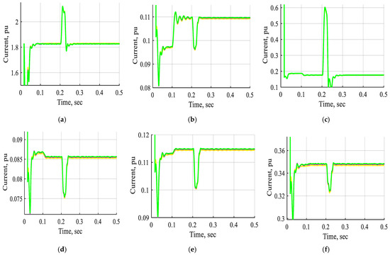
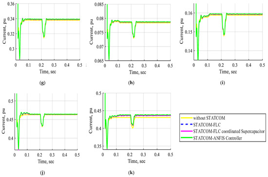
Figure 20.
The current waveform of buses B1, B2, B3, B4, B5, B6, B7, B8, B9, B10, and B11 in pu without STATCOM, without STATCOM, with STATCOM-FLC, with STATCOM-FLC coordinated supercapacitor, and with STATCOM-ANFIS controller for single line-to-ground fault near bus B3 at t = (0.2–0.21) s. (a) The current waveform of bus B1 in pu. (b) The current waveform of bus B2 in pu. (c) The current waveform of bus B3 in pu. (d) The current waveform of bus B4 in pu. (e) The current waveform of bus B5 in pu. (f) The current waveform of bus B6 in pu. (g) The current waveform of bus B7 in pu. (h) The current waveform of bus B8 in pu. (i) The current waveform of bus B9 in pu. (j) The current waveform of bus B10 in pu. (k) The current waveform of bus B11 in pu.
Figure 21 shows the DC voltage behavior of the STATCOM-FLC, STATCOM-FLC-coordinated supercapacitor, and STATCOM-ANFIS controller during a single line-to-ground fault near bus B3. The results demonstrated that the STATCOM-ANFIS controller maintains superior system performance compared to other controllers, as evidenced by minimal DC voltage deviations despite the fault occurrence.

Figure 21.
The DC voltage wave shapes of STATCOM-FLC, STATCOM-FLC coordinated supercapacitor, and STATCOM-ANFIS controller for single line-to-ground fault near bus B3 at t = (0.2–0.21) s. (a) The DC voltage wave shape of STAT-COM-FLC. (b) The DC voltage wave shape of STAT-COM-FLC coordinated supercapacitor. (c) The DC voltage wave shape of STATCOM-ANFIS controller.
Case 5:
The electrical network under a three-line-to-ground fault was inserted near bus B3 without STATCOM, with STATCOM-FLC, with STATCOM-FLC coordinated supercapacitor, and with STATCOM-ANFIS controller.
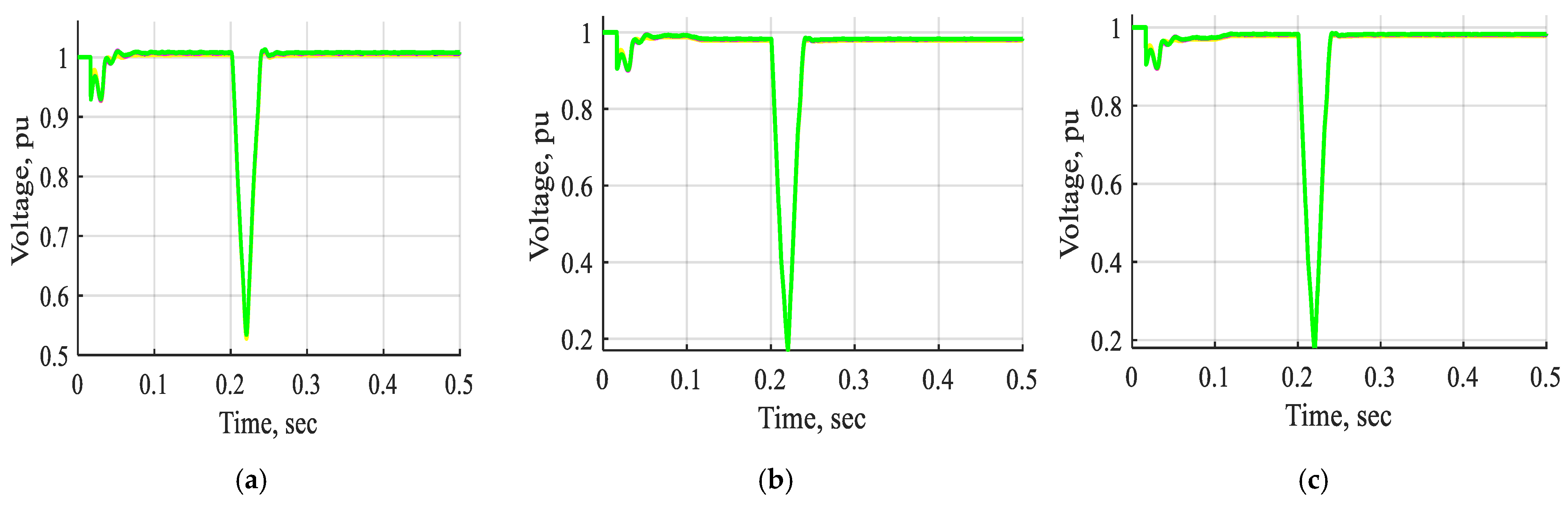
Figure 22 and Figure 23 display the voltage and current waveforms of bus B1 to bus B11 without STATCOM, with STATCOM-FLC, with STATCOM-FLC coordinated supercapacitor, and with STATCOM-ANFIS controller under a three-line-to-ground fault inserted near bus B3. The waveforms demonstrated significant variations in voltage and current during the interval from t = 0.2 s to 0.21 s, associated with a three-line-to-ground fault near bus B3. The figures demonstrate that the voltage and current waveforms from bus B1 to bus B11 during a three-phase line-to-ground fault near bus B3 were significantly improved when utilizing a STATCOM with an ANFIS controller, compared to fuzzy controllers or non-FACTS devices. The STATCOM-ANFIS controller system demonstrated a shorter stabilization time compared to other systems during a three-line-to-ground fault. The system’s stability under fault conditions is improved by implementing a STATCOM utilizing an ANFIS controller.
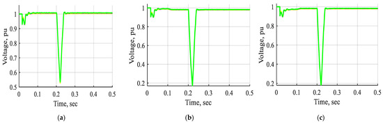
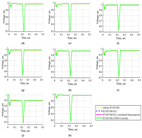
Figure 22.
The voltage waveform of buses B1, B2, B3, B4, B5, B6, B7, B8, B9, B10, and B11 in pu without STATCOM, without STATCOM, with STATCOM-FLC, with STATCOM-FLC coordinated supercapacitor, and with STATCOM-ANFIS controller for three-line-to-ground fault near bus B3 at t = (0.2–0.21) s. (a) The voltage waveform of bus B1 in pu. (b) The voltage waveform of bus B2 in pu. (c) The voltage waveform of bus B3 in pu. (d) The voltage waveform of bus B4 in pu. (e) The voltage waveform of bus B5 in pu. (f) The voltage waveform of bus B6 in pu. (g) The voltage waveform of bus B7 in pu. (h) The voltage waveform of bus B8 in pu. (i) The voltage waveform of bus B9 in pu. (j) The voltage waveform of bus B10 in pu. (k) The voltage waveform of bus B11 in pu.
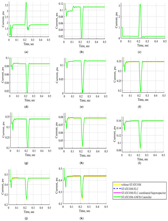
Figure 23.
The current waveform of buses B1, B2, B3, B4, B5, B6, B7, B8, B9, B10, and B11 in pu without STATCOM, without STATCOM, with STATCOM-FLC, with STATCOM-FLC coordinated supercapacitor, and with STATCOM-ANFIS controller for three-line-to-ground fault near bus B3 at t = (0.2–0.21) s. (a) The current waveform of bus B1 in pu. (b) The current waveform of bus B2 in pu. (c) The current waveform of bus B3 in pu. (d) The current waveform of bus B4 in pu. (e) The current waveform of bus B5 in pu. (f) The current waveform of bus B6 in pu. (g) The current waveform of bus B7 in pu. (h) The current waveform of bus B8 in pu. (i) The current waveform of bus B9 in pu. (j) The current waveform of bus B10 in pu. (k) The current waveform of bus B11 in pu.
Figure 24 shows the DC voltage waveform of the STATCOM-FLC, the STATCOM-FLC-coordinated supercapacitor, and the STATCOM-ANFIS controller during the three-line-to-ground fault occurring near bus B3. The DC voltage waveform introduced a minor voltage adjustment, enhancing the system performance with the STATCOM-ANFIS controller compared to the other controllers, despite the occurrence of a three-line-to-ground fault.
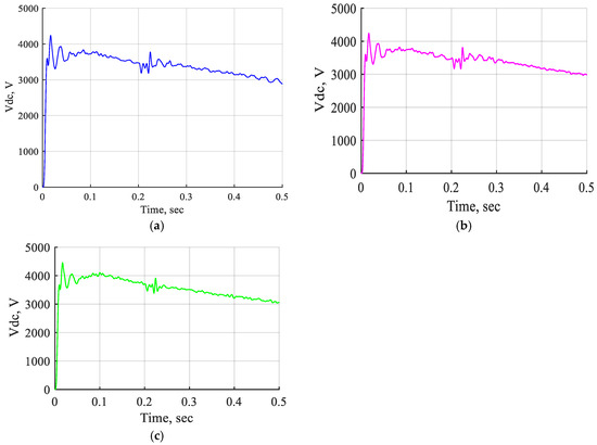
Figure 24.
The DC voltage wave shapes of STATCOM-FLC, STATCOM-FLC coordinated supercapacitor, and STATCOM-ANFIS controller for three-line-to-ground fault near bus B3 at t = (0.2–0.21) s. (a) The DC voltage wave shape of intelligent STATCOM. (b) The DC voltage wave shape of intelligent STATCOM-supercapacitor. (c) The DC voltage wave shape of STATCOM with ANFIS controller.
Case 6:
The electrical network using two STATCOM units coordinated with the ANFIS controller at normal operation and was inserted near bus B3 under a three-line-to-ground fault.
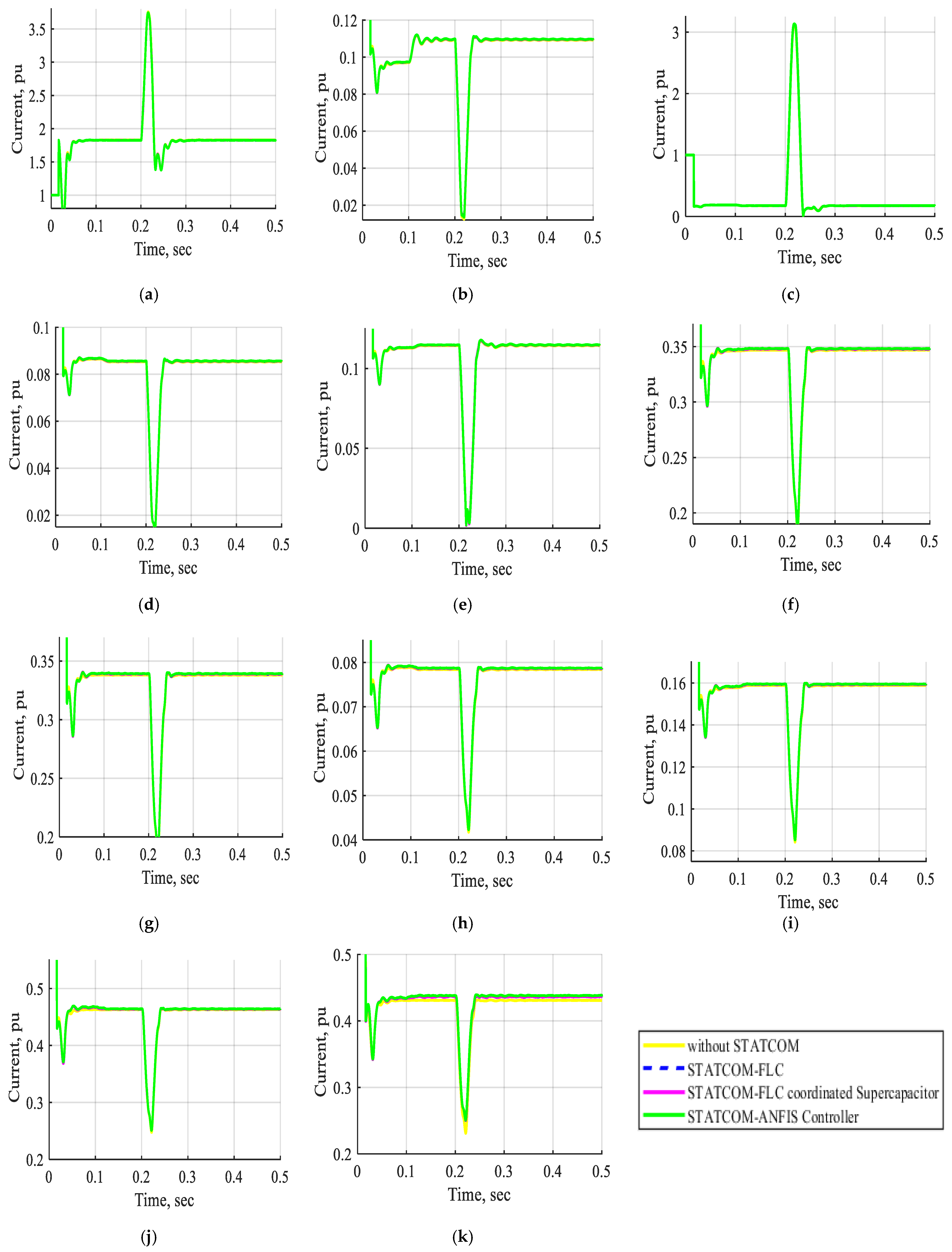
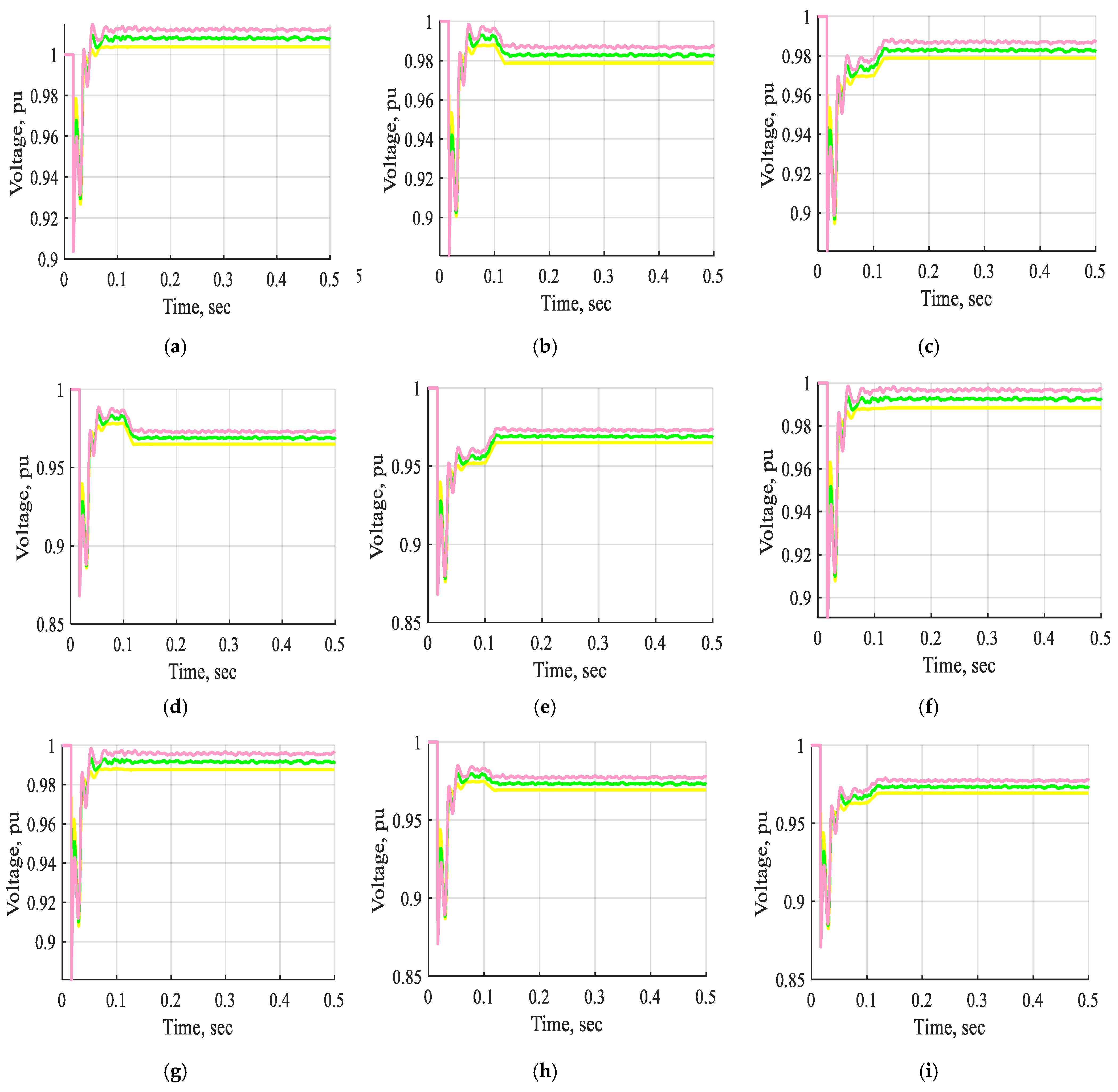
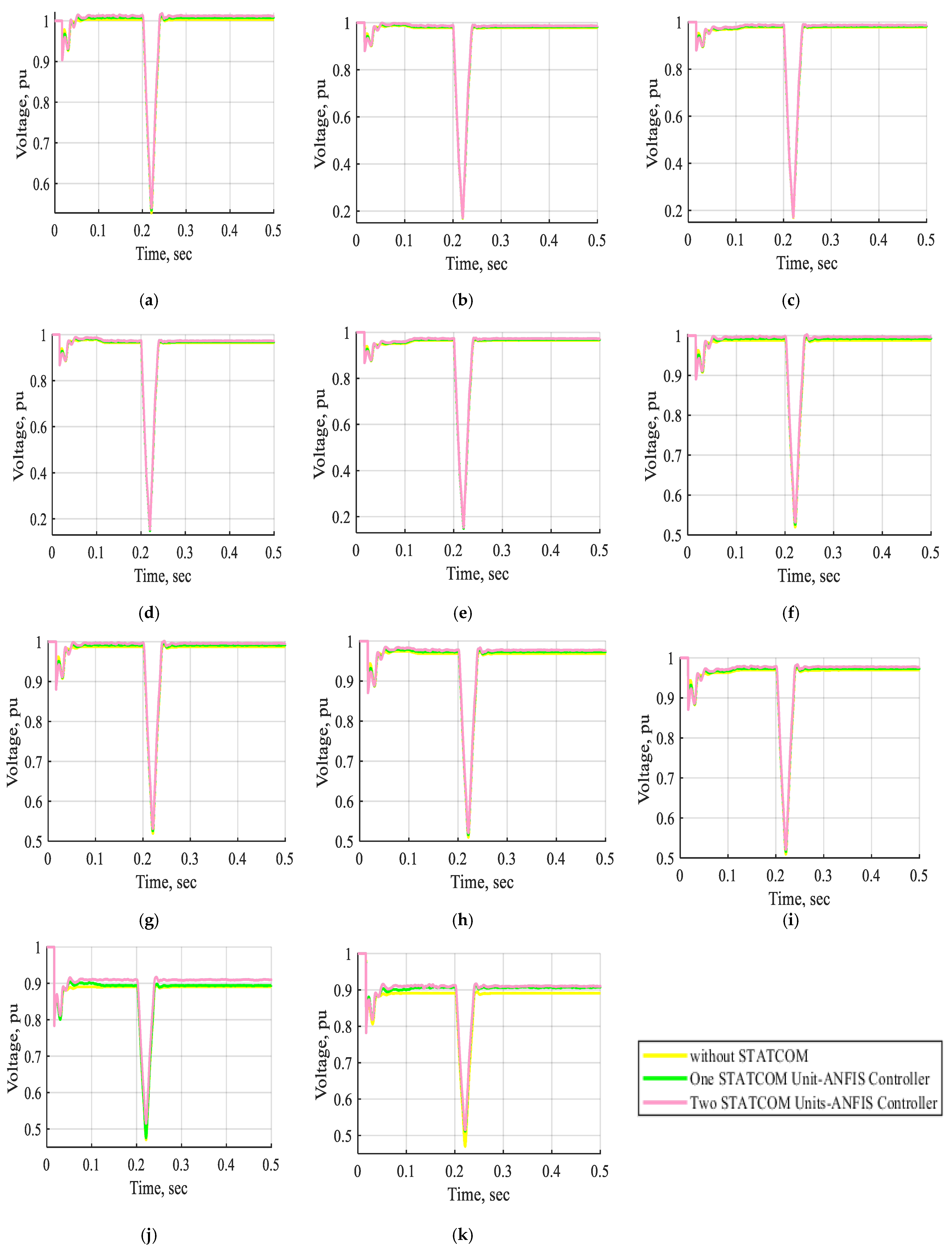
Figure 25 and Figure 26 show the voltage and current waveforms of buses B1 to B11 during normal operation under three conditions: without a STATCOM, with one STATCOM unit, and with two STATCOM units coordinated using an ANFIS controller. The single STATCOM unit (25 MVA, 66 kV) is connected to the shunt at bus B11, whereas the two STATCOM units (each 25 MVA, 66 kV) are connected in the shunt at buses B10 and B11, respectively. These figures demonstrate that the voltage and current waveforms of buses B1 to B11 significantly improve when two STATCOM units coordinated by an ANFIS controller are used, compared to using only one STATCOM unit or no STATCOM device. Consequently, the system’s performance during normal operation is significantly enhanced using two STATCOM units with an ANFIS controller.
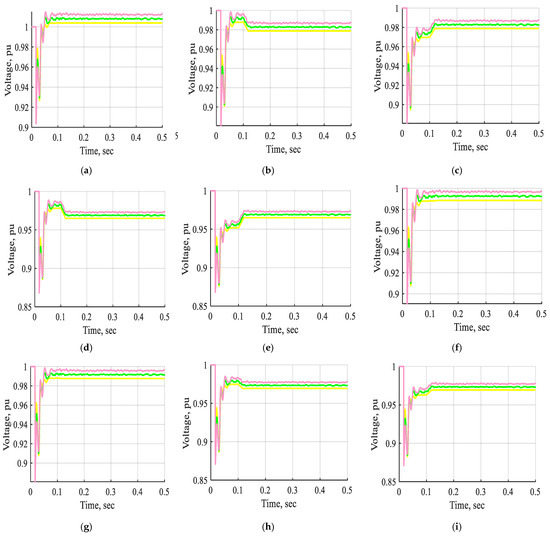
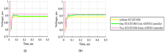
Figure 25.
The voltage waveform of buses B1, B2, B3, B4, B5, B6, B7, B8, B9, B10, and B11 in pu without STATCOM, without STATCOM, with one STATCOM unit, and with two STATCOM units coordinated with an ANFIS controller at normal operation. (a) The voltage waveform of bus B1 in pu. (b) The voltage waveform of bus B2 in pu. (c) The voltage waveform of bus B3 in pu. (d) The voltage waveform of bus B4 in pu. (e) The voltage waveform of bus B5 in pu. (f) The voltage waveform of bus B6 in pu. (g) The voltage waveform of bus B7 in pu. (h) The voltage waveform of bus B8 in pu. (i) The voltage waveform of bus B9 in pu. (j) The voltage waveform of bus B10 in pu. (k) The voltage waveform of bus B11 in pu.
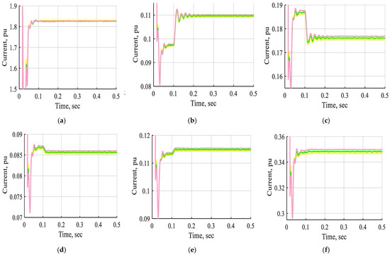
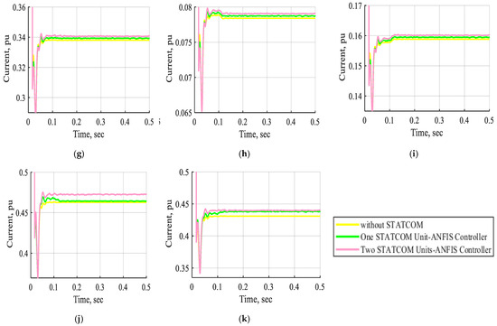
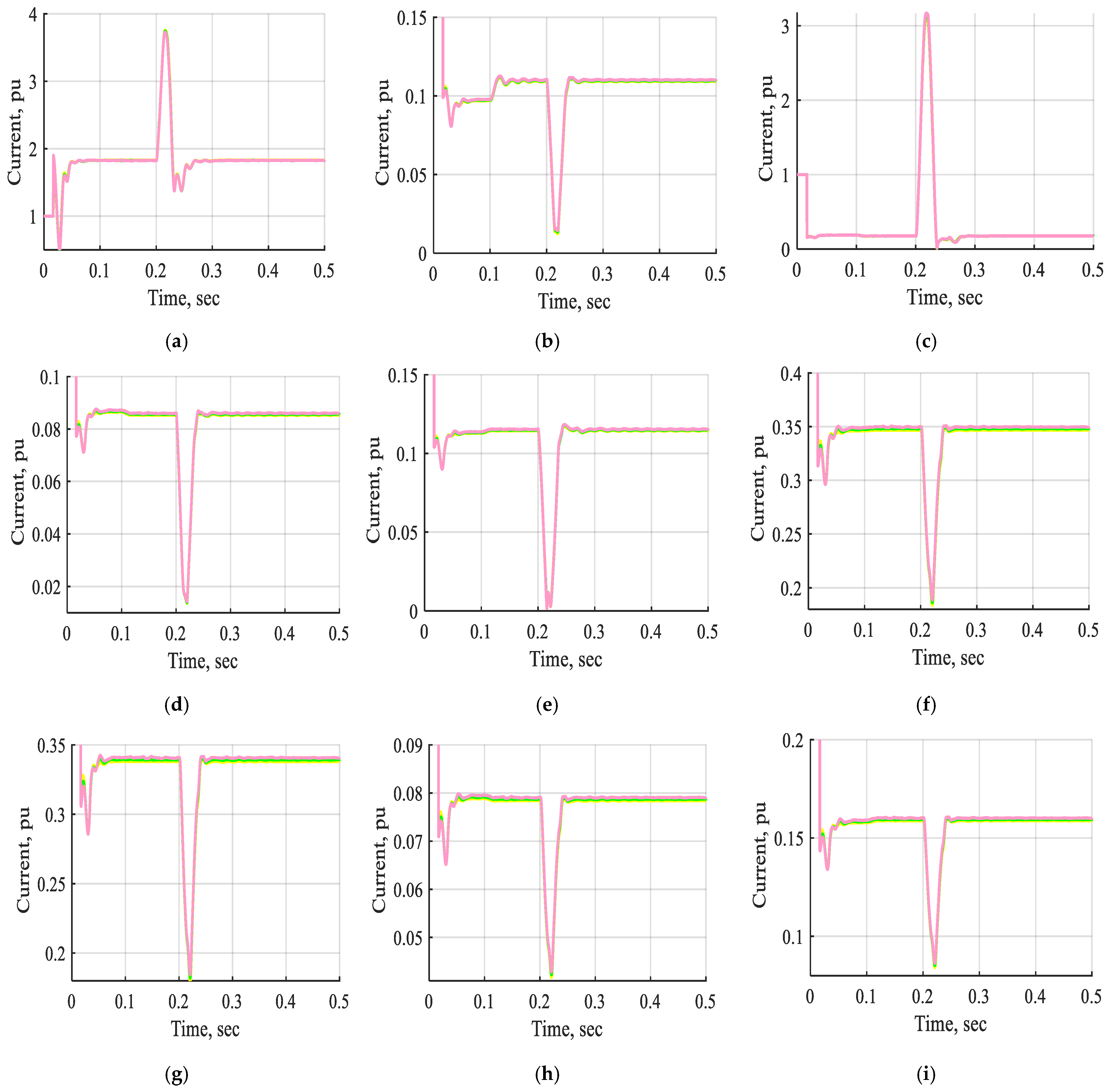
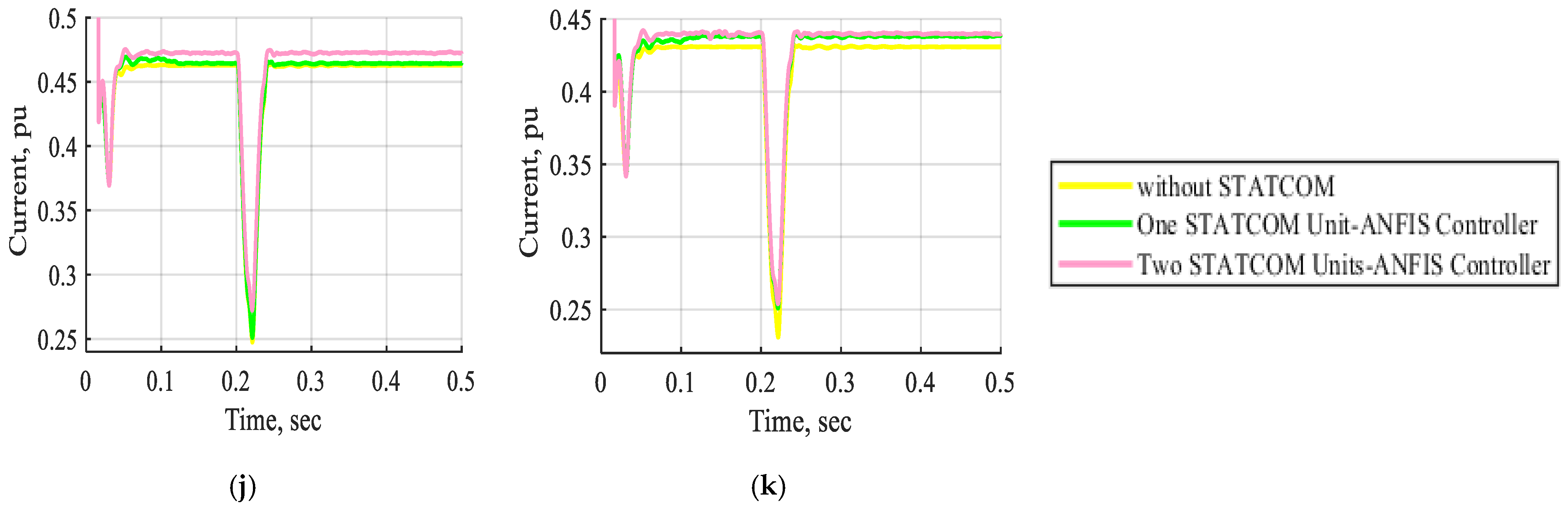
Figure 26.
The current waveform of buses B1, B2, B3, B4, B5, B6, B7, B8, B9, B10, and B11 in pu without STATCOM, with one STATCOM unit, and with two STATCOM units coordinated with an ANFIS controller at normal operation. (a) The current waveform of bus B1 in pu. (b) The current waveform of bus B2 in pu. (c) The current waveform of bus B3 in pu. (d) The current waveform of bus B4 in pu. (e) The current waveform of bus B5 in pu. (f) The current waveform of bus B6 in pu. (g) The current waveform of bus B7 in pu. (h) The current waveform of bus B8 in pu. (i) The current waveform of bus B9 in pu. (j) The current waveform of bus B10 in pu. (k) The current waveform of bus B11 in pu.
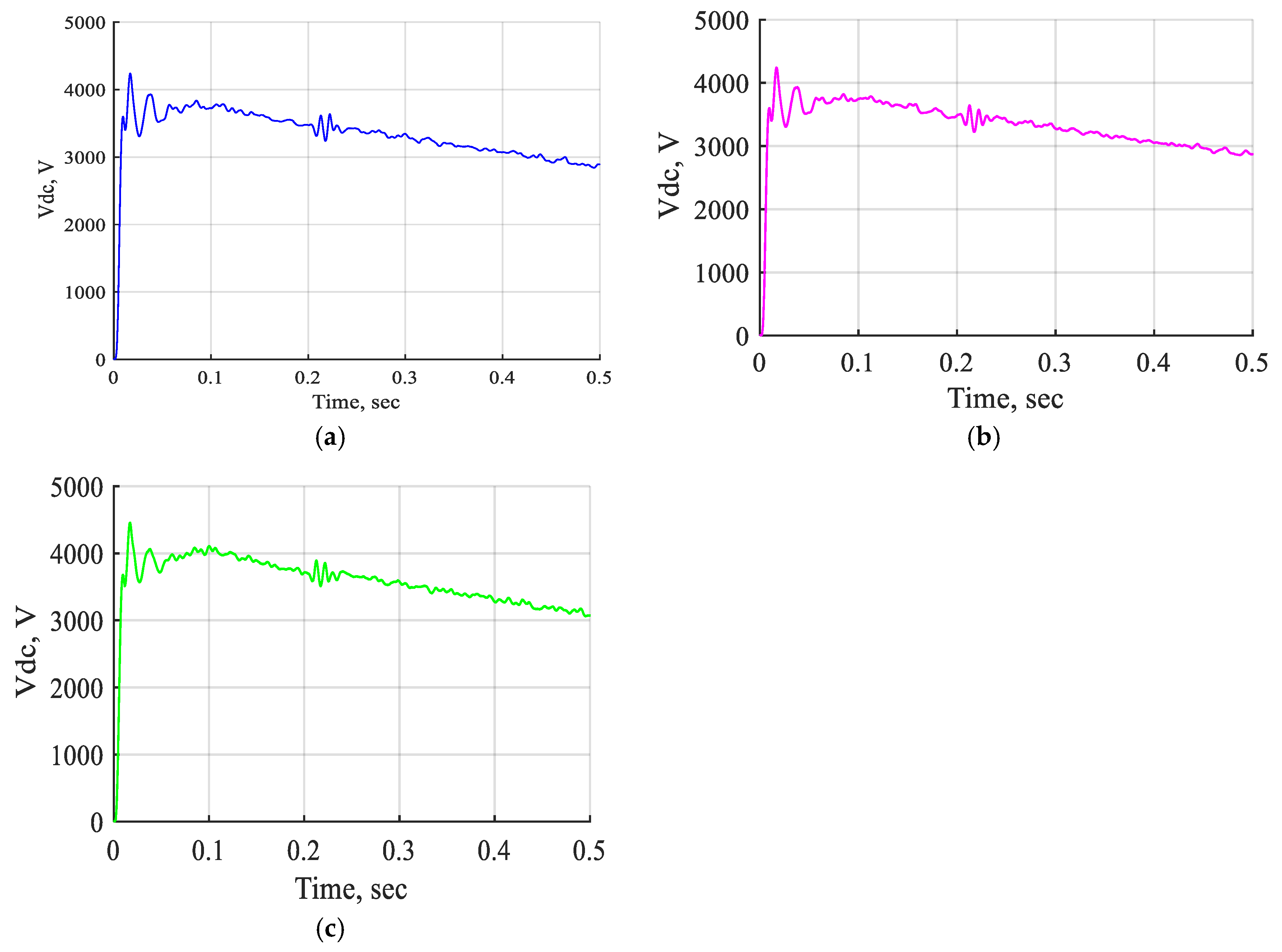
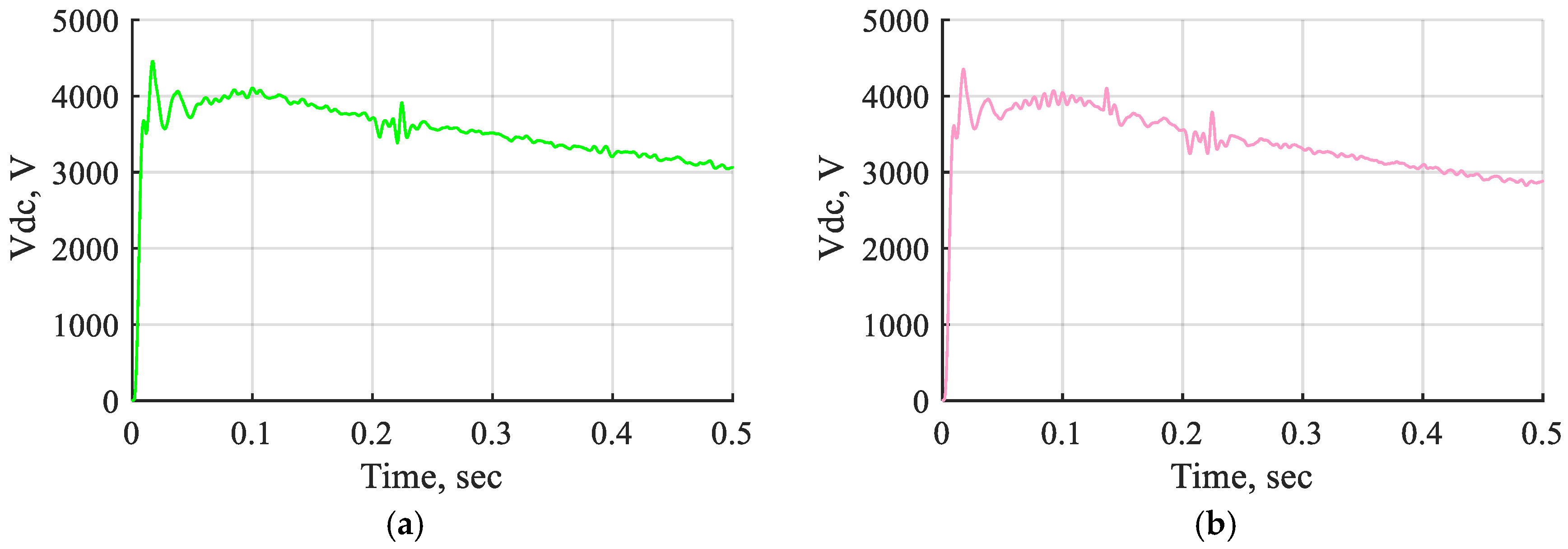
Figure 27 shows the DC voltage waveform of one STATCOM unit and two STATCOM units with an ANFIS controller at normal operation. It is observed that the DC voltage waveform contributes a small change in voltage due to the use of the STATCOM-ANFIS controller, which is either one or two units at normal operation.
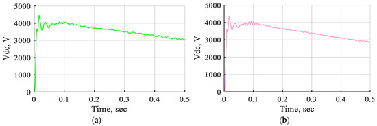
Figure 27.
The DC voltage waveform of one STATCOM unit and two STATCOM units coordinated with the ANFIS controller at normal operation. (a) The DC voltage waveform of one STATCOM unit with ANFIS controller. (b) The DC voltage waveform of two STATCOM units with ANFIS controller.
The effects of one and two STATCOM units with the ANFIS controller on the system bus voltage in pu during normal operation are presented in Table 6. The improvement in the bus voltage is evident when utilizing two STATCOM units controlled by an ANFIS controller during normal operation. A comparison of the voltage levels at buses B10 and B11 reveals that the coordinated operation of the two STATCOM units enhances the bus voltage to 102.122% and 102.200%, respectively, compared with their values without any STATCOM devices. In contrast, using a single STATCOM unit conducts voltage increases of only 100.382% and 101.953%, respectively. Therefore, the two STATCOM units with the ANFIS controller demonstrated superior performance compared with the other configurations.
Table 6.
Effect of one and two STATCOM units with ANFIS controller in system buses’ voltage in pu under normal operating conditions.
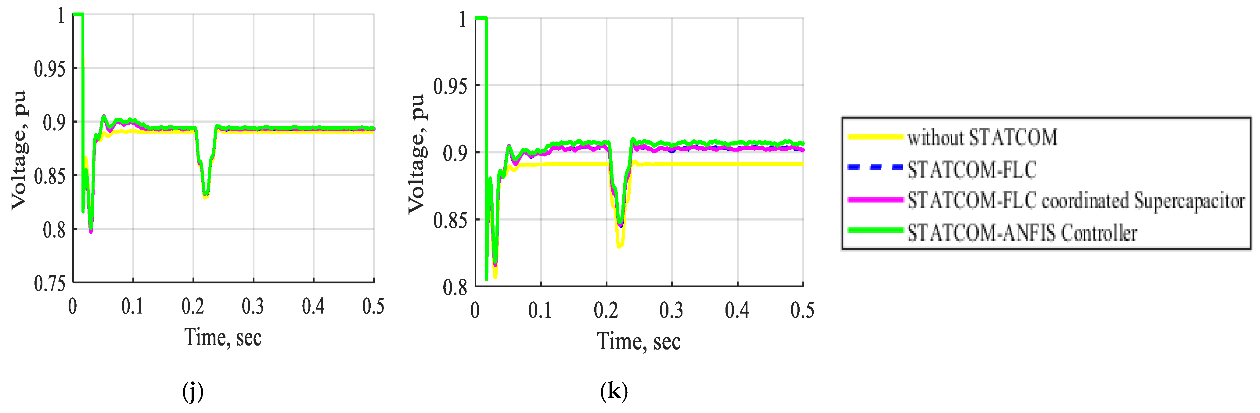
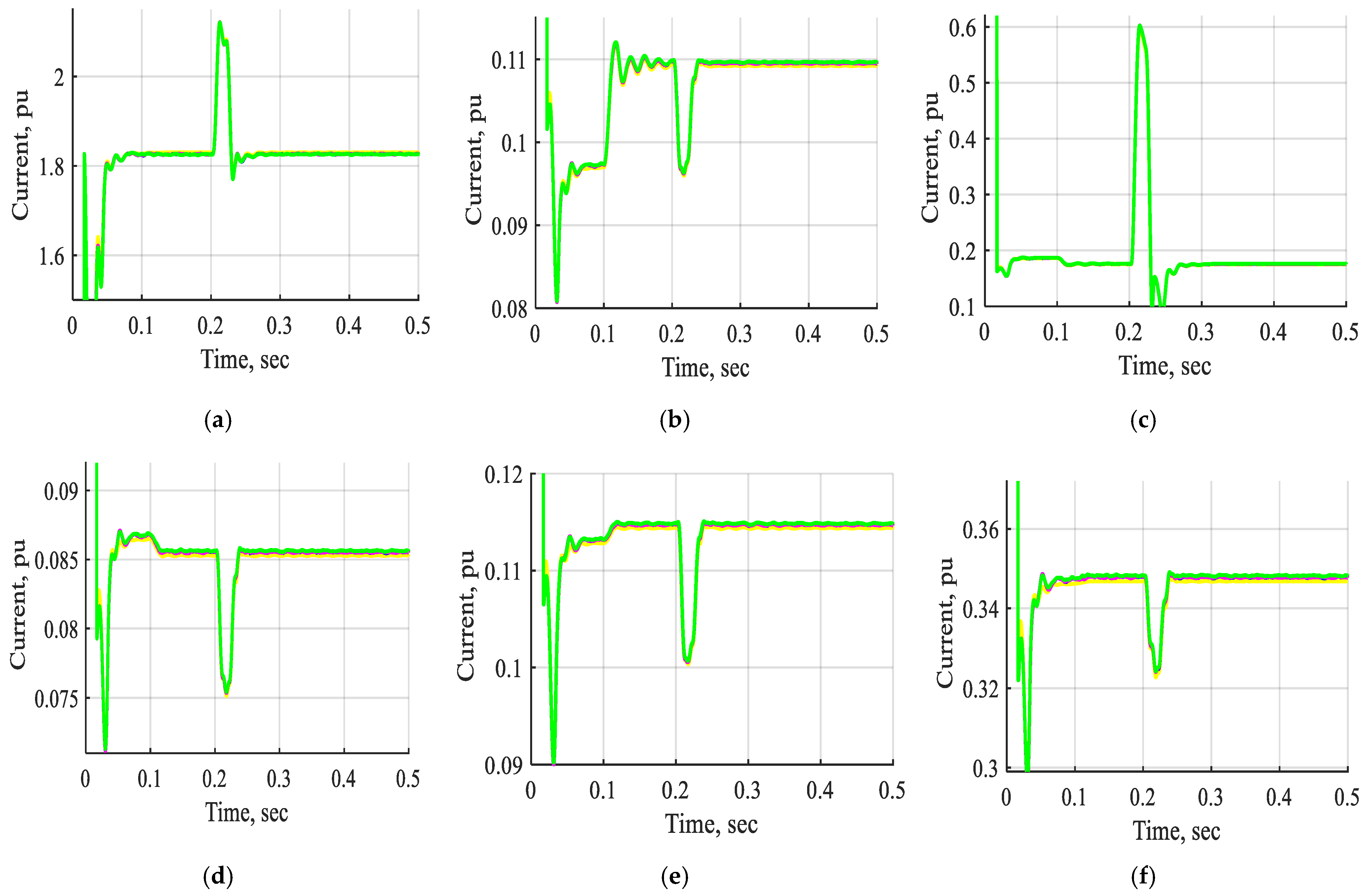
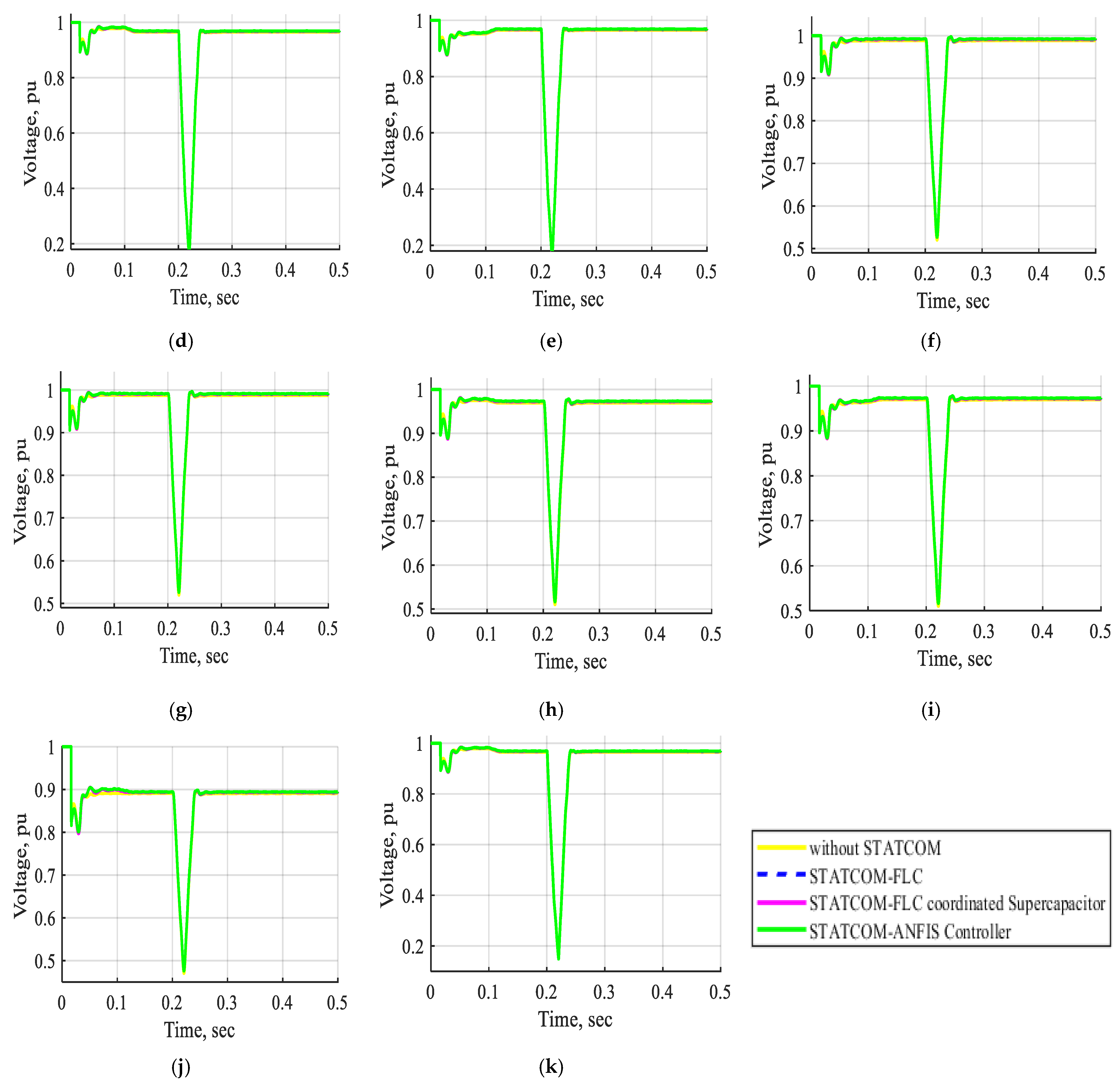
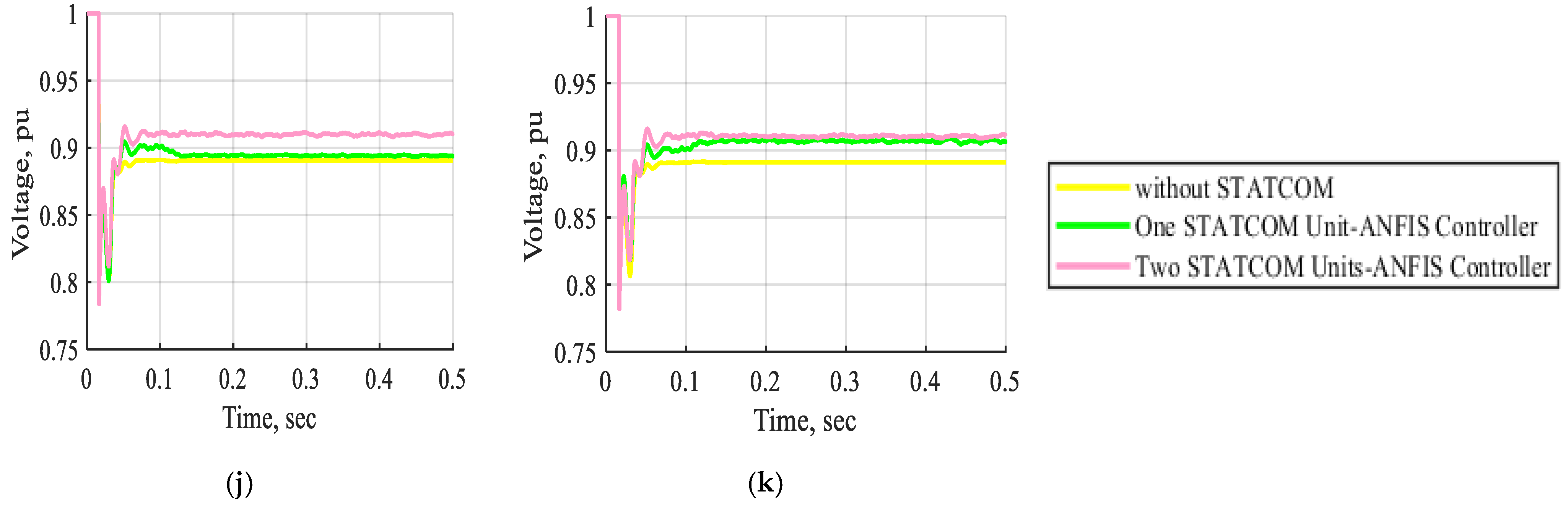
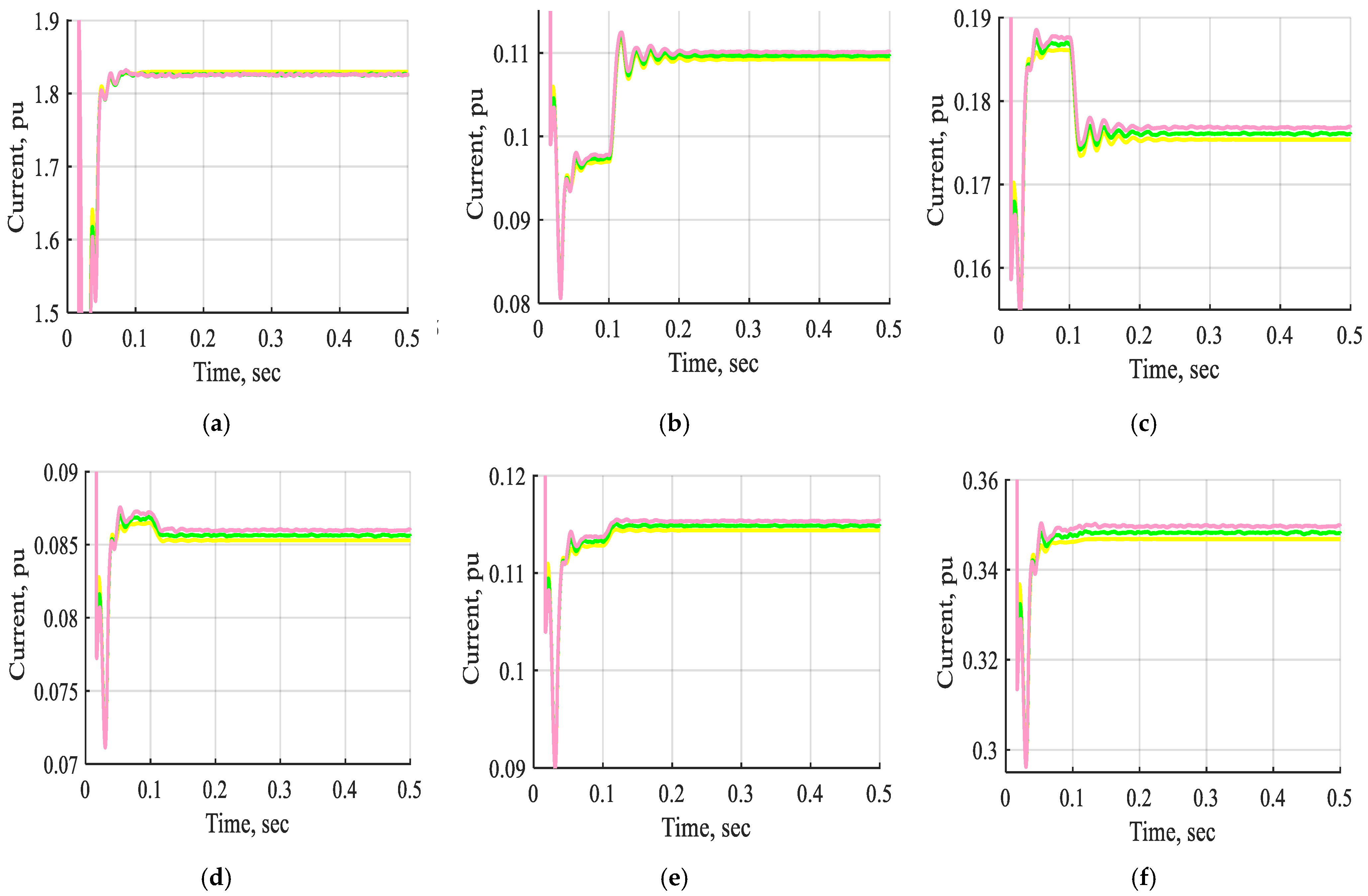
Figure 28 and Figure 29 display the voltage and current waveforms of bus B1 to bus B11 without STATCOM, with one STATCOM unit and two STATCOM units coordinated to the ANFIS controller under a three-line-to-ground fault inserted near bus B3. These waveforms demonstrate that the voltage and current are changed comprehensively in the period from t = 0.2 s to 0.21 s through a three-line-to-ground fault near bus B3. These Figs indicate that the voltage and current waveforms of bus B1 to bus B11, with a three-line-to-ground fault near bus B3 using two STATCOM units based on the ANFIS controller, are enhanced extensively by more than one STATCOM unit or by not using the STATCOM device. Additionally, the system with two STATCOM units takes less time to stabilize than the other one under the three-line-to-ground fault. Accordingly, the system stability under a three-line-to-ground fault is enhanced using two STATCOM units based on the ANFIS controller rather than one STATCOM unit.
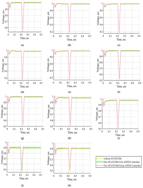
Figure 28.
The voltage waveform of buses B1, B2, B3, B4, B5, B6, B7, B8, B9, B10, and B11 in pu without STATCOM, with one STATCOM unit, and with two STATCOM units coordinated with an ANFIS controller for a three-line-to-ground fault near bus B3 at t = (0.2–0.21) s. (a) The voltage waveform of bus B1 in pu. (b) The voltage waveform of bus B2 in pu. (c) The voltage waveform of bus B3 in pu. (d) The voltage waveform of bus B4 in pu. (e) The voltage waveform of bus B5 in pu. (f) The voltage waveform of bus B6 in pu. (g) The voltage waveform of bus B7 in pu. (h) The voltage waveform of bus B8 in pu. (i) The voltage waveform of bus B9 in pu. (j) The voltage waveform of bus B10 in pu. (k) The voltage waveform of bus B11 in pu.
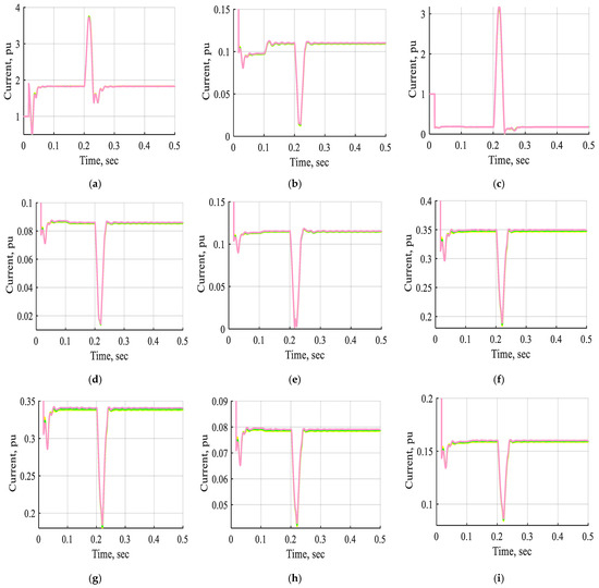
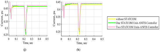
Figure 29.
The current waveform of buses B1, B2, B3, B4, B5, B6, B7, B8, B9, B10, and B11 in pu without STATCOM, with one STATCOM unit, and with two STATCOM units coordinated with ANFIS controller for a three-line-to-ground fault near bus B3 at t = (0.2–0.21) s. (a) The current waveform of bus B1 in pu. (b) The current waveform of bus B2 in pu. (c) The current waveform of bus B3 in pu. (d) The current waveform of bus B4 in pu. (e) The current waveform of bus B5 in pu. (f) The current waveform of bus B6 in pu. (g) The current waveform of bus B7 in pu. (h) The current waveform of bus B8 in pu. (i) The current waveform of bus B9 in pu. (j) The current waveform of bus B10 in pu. (k) The current waveform of bus B11 in pu.
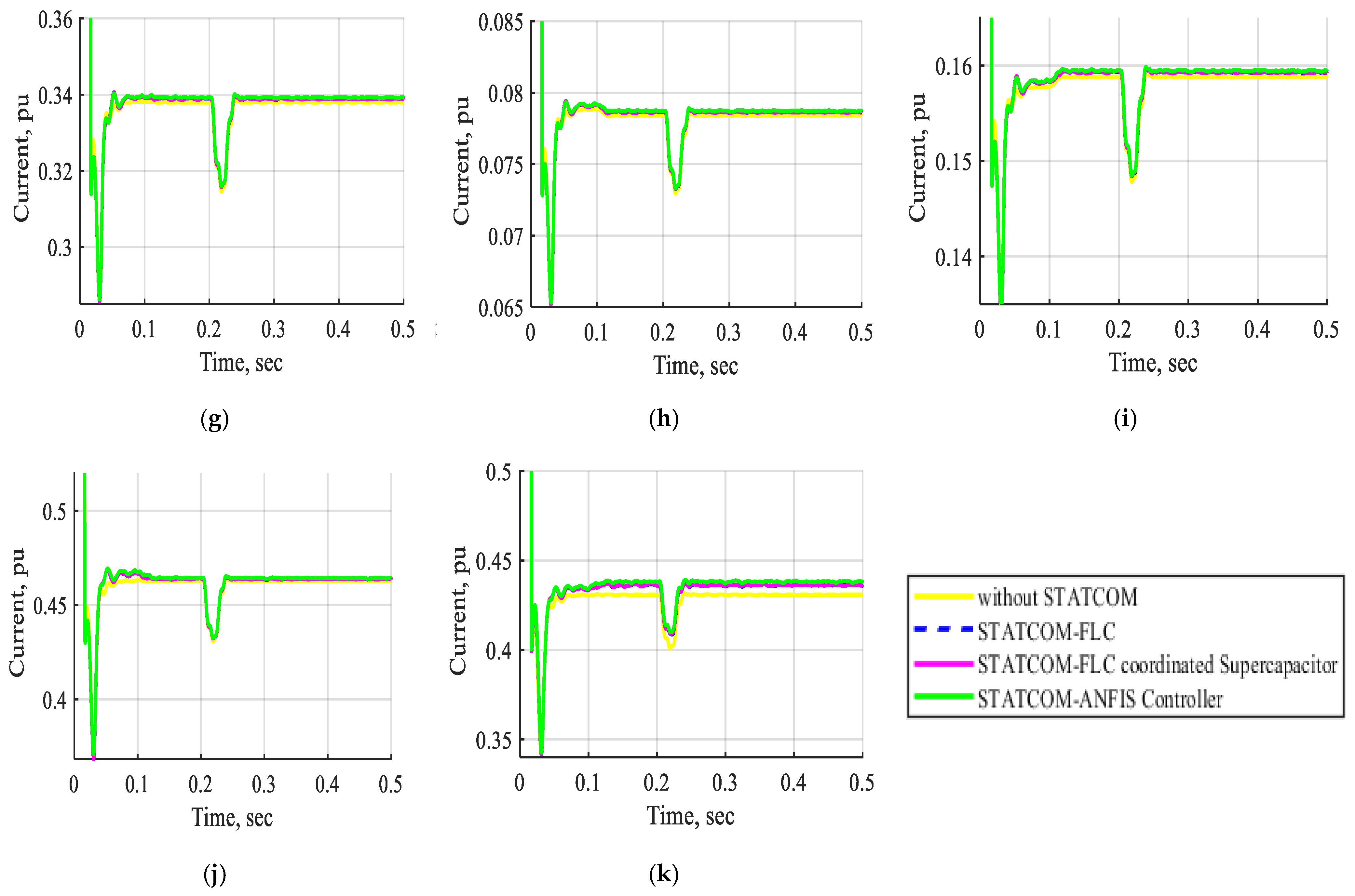
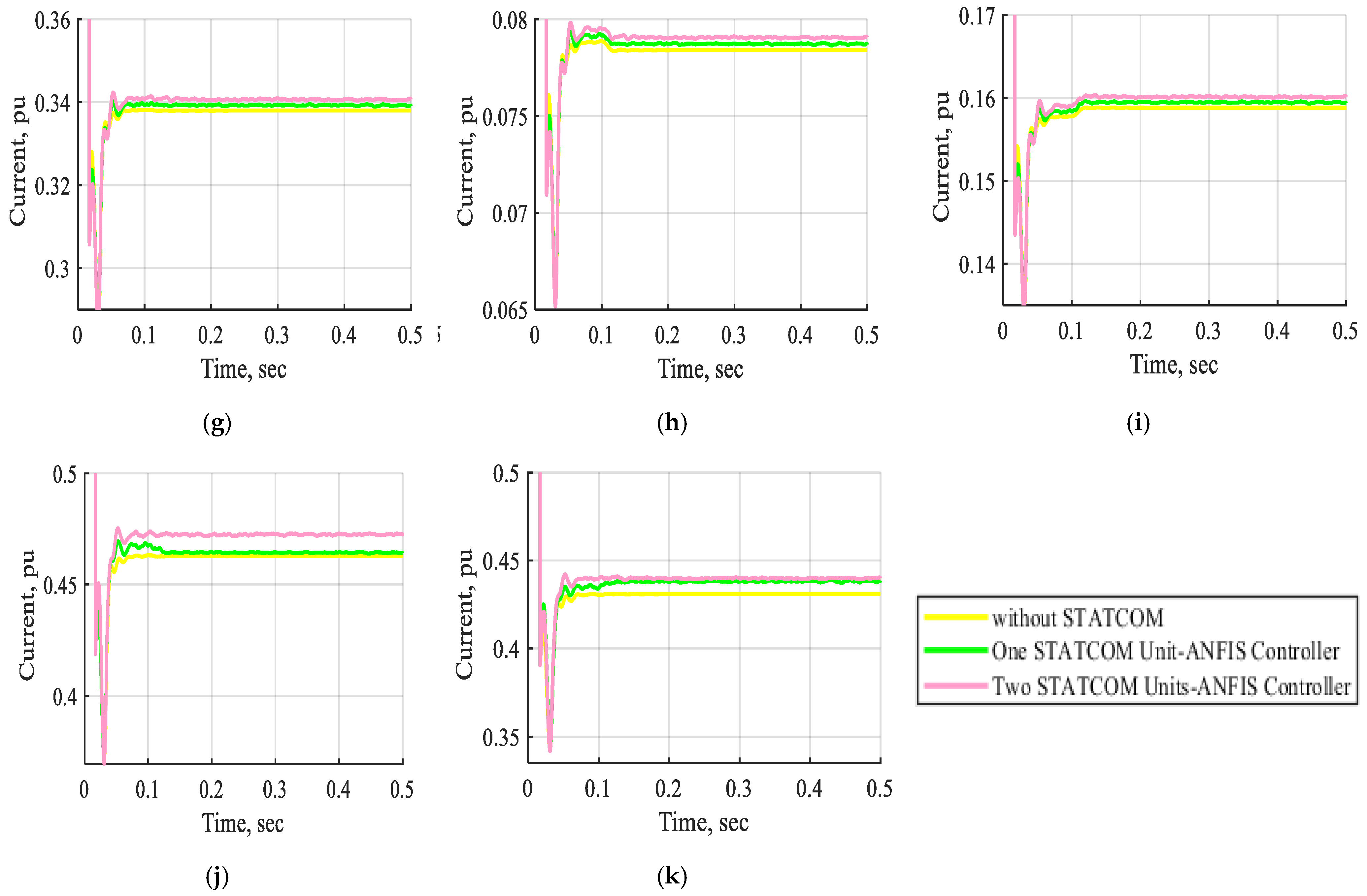
Figure 30 shows the DC voltage waveform of one STATCOM unit and two STATCOM units with an ANFIS controller for a three-line-to-ground fault near bus B3 at t = (0.2–0.21) sec. The DC voltage waveform exhibits a minor voltage variation due to the implementation of the STATCOM-ANFIS controller, regardless of whether one or two units are utilized, even in the presence of a three-line-to-ground fault.
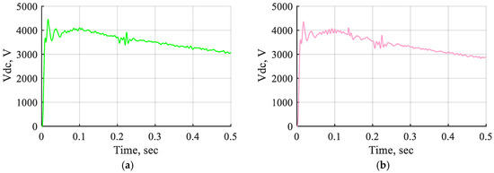
Figure 30.
The DC voltage waveform of one STATCOM unit and two STATCOM units coordinated with the ANFIS controller for a three-line-to-ground fault near bus B3 at t = (0.2–0.21) s. (a) The DC voltage waveform of one STATCOM unit with ANFIS controller. (b) The DC voltage waveform of two STATCOM units with ANFIS controller.
5. Conclusions
This study modeled the electrical transmission network in the Middle Egypt Electricity Zone using a STATCOM-integrated ANFIS controller. The system stability was evaluated under normal operation, voltage source variations, and fault conditions via MATLAB/Simulink simulations. The STATCOM’s performance was assessed using multiple controllers: a PI controller, FLC, FLC with a supercapacitor, and an ANFIS controller. A comparative analysis of the voltage and current waveforms across these controllers was conducted. The proposed STATCOM effectively regulated the power system voltage profile, maintaining deviations within ±10% of its nominal value. The findings demonstrated that the STATCOM device with the ANFIS controller improves the power system voltage and current, demonstrating superior performance with reduced oscillation compared to the FLC, FLC-coordinated supercapacitor, and PI controller across various conditions. The implementation of two STATCOM units with an ANFIS controller yielded superior system performance compared to a single unit across various conditions. The results demonstrate that a single STATCOM device, managed by an ANFIS controller under normal operating conditions, can substantially increase the voltages at buses B10 and B11 to (100.382, 101.953) % of their original levels without the presence of a STATCOM unit. In contrast, the use of an FLC leads to voltage increases of 100.3144% for B10 and 101.246% for B11, whereas the FLC combined with a supercapacitor results in voltages of 100.326% and 101.392%, respectively. The implementation of two STATCOM units utilizing the ANFIS controller results in voltage enhancements of 102.122% and 102.200%. Future research may investigate the system utilizing additional FACTS devices, including the SSSC and UPFC, under various abnormal conditions at different locations. Moreover, renewable resources, including solar and wind energy, can be analyzed across various scenarios within the system.
Author Contributions
Methodology: A.A.Z.D., S.A.D. and I.Y.F.; Validation: A.A.Z.D., A.M.E. and A.G.A.E.-M.; Formal analysis: S.A.D., I.Y.F. and A.A.Z.D.; Investigation: I.Y.F. and A.A.Z.D.; Writing—original draft preparation: I.Y.F., A.G.A.E.-M. and A.A.Z.D.; writing—review and editing, I.Y.F., A.G.A.E.-M., A.A.Z.D. and S.A.D.; Supervision, A.A.Z.D. and A.M.E. All authors have read and agreed to the published version of the manuscript.
Funding
This research received no external funding.
Data Availability Statement
The original contributions presented in this study are included in the article. Further inquiries can be directed to the corresponding author.
Conflicts of Interest
The authors declare no conflicts of interest.
Abbreviations
The abbreviations listed below are utilized in this manuscript:
| STATCOM | Static Synchronous Compensation Device |
| FACTS | Flexible AC Transmission Systems |
| PI | Proportional Integral |
| PID | Proportional Integral Derivative |
| FLC | Fuzzy Logic Controller |
| ANFIS | Adaptive Neuro Fuzzy Inference System |
| PCC | Point of Common Coupling |
| SVC | Static VAR Compensator |
| TSR/TSC | Thyristor Switched Reactors/Capacitors |
| SSSC | Static Synchronous Series Compensation Device |
| UPFC | Unified Power Flow Controller |
| ANN | Artificial Neural Network |
| AI | Artificial Intelligence |
| NB | Negative Big |
| NM | Negative Medium |
| NS | Negative Small |
| ZE | Zero |
| PS | Positive Small |
| PM | Positive Medium |
| PB | Positive Big |
| VSC | Voltage Source Converter |
References
- Urrea-Aguirre, C.; Saldarriaga-Zuluaga, S.D.; Bustamante-Mesa, S.; López-Lezama, J.M.; Muñoz-Galeano, N. Optimal Placement and Sizing of Modular Series Static Synchronous Compensators (M-SSSCs) for Enhanced Transmission Line Loadability, Loss Reduction, and Stability Improvement. Processes 2024, 13, 34. [Google Scholar] [CrossRef]
- Gadupudi, L.; Rao, G.S.; Narayana Divakar, R.V.L.; Malik, H.; Alsaif, F.; Alsulamy, S.; Ustun, T.S. Fuzzy-Based Fifteen-Level VSC for STATCOM Operations with Single DC-Link Voltage. Sustainability 2023, 15, 6188. [Google Scholar] [CrossRef]
- Abdollahi Chirani, A.; Karami, A. Investigation of the Impact of SSSC-Based FLC on the Stability of Power Systems Connected to Wind Farms. Int. Trans. Electr. Energy Syst. 2024, 2024, 1074029. [Google Scholar] [CrossRef]
- Bouhadouza, B.; Bouktir, T.; Bourenane, A. Transient Stability Augmentation of the Algerian South-Eastern Power System including PV Systems and STATCOM. Eng. Technol. Appl. Sci. Res. 2020, 10, 5660–5667. [Google Scholar] [CrossRef]
- Hafez, A.A. Synergy of simulated annealing and particle swarm algorithms for optimizing statcom damping controller. J. Eng. Sci. 2015, 43, 857–881. [Google Scholar] [CrossRef]
- Shah, N.M.; Sood, V.K.; Ramachandran, V. Modeling, control and simulation of a chain link STATCOM in EMTP-RV. Electr. Power Syst. Res. 2009, 79, 474–483. [Google Scholar] [CrossRef]
- Hingorani, N.G.; Gyugyi, L. Understanding FACTS: Concepts and Technology of Flexible AC Transmission Systems; Wiley-IEEE Press: Piscataway, NJ, USA, 2000. [Google Scholar]
- Mehedi, I.M.; Al Hasan Joy, J.; Islam, M.R.; Hasan, N.; Al-Saggaf, U.M.; Milyani, A.H.; Iskanderani, A.I.; Abusorrah, A.; Rawa, M.; Bassi, H. Reducing fault current by using FACTS devices to improve electrical power flow. Math. Probl. Eng. 2021, 2021, 8116816. [Google Scholar] [CrossRef]
- Rohit, M.; Sharma, N.K. Improvement of Transmission Line Voltage Using Facts. Int. J. Curr. Sci. 2022, 12, 499–507. [Google Scholar]
- Wara, M.R.; Rahim, A. STATCOM in Power Systems: A Review. Int. J. Power Electron. Controll. Convert. 2020, 6, 39–51. [Google Scholar]
- Noureldeen, O.; Rihan, M.; Hasanin, B. Impact of fault location and duration on the stability of wind farm interconnected grid. J. Eng. Sci. 2011, 39, 145–160. [Google Scholar] [CrossRef]
- Xu, Y.; Li, F. Adaptive PI control of STATCOM for voltage regulation. IEEE Trans. Power Deliv. 2014, 29, 1002–1011. [Google Scholar] [CrossRef]
- Al-Hadithi, B.M.; Gómez, J. Fuzzy Control of Multivariable Nonlinear Systems Using T–S Fuzzy Model and Principal Component Analysis Technique. Processes 2025, 13, 217. [Google Scholar] [CrossRef]
- Reddy, S.; Prasad, P.; Srinivas, G. Design of PI and fuzzy logic controllers for distribution static compensator. Int. J. Power Electron. Drive Syst. 2018, 9, 465. [Google Scholar] [CrossRef]
- Masoumi, M.; Hossani, S.; Dehghani, F.; Masoumi, A. The challenges and advantages of fuzzy systems applications. A Prepr. 2020, 1. [Google Scholar] [CrossRef]
- Somalwar, R.; Khemariya, M. A Review of Enhancement of Transient Stability by FACTS Devices. Int. J. Emerg. Technol. Sci. Eng. 2012, 5, 72–76. [Google Scholar]
- Shaaban, F.; Harmoosh, Z.; Alsari, E. Enhancement of voltage stability in power transmission networks using static compensator (STATCOM) based on fuzzy logic. Tishreen Univ. J. Res. Sci. Stud. -Eng. Sci. Ser. 2017, 39, 387–404. [Google Scholar]
- Sundararaju, K.; Senthilkumar, R. Modelling and analysis of real time power system with cascaded multilevel STATCOM using fuzzy controller. J. Adv. Chem. 2016, 12, 4408–4417. [Google Scholar]
- Kumkratug, P. STATCOM Stabilizer based on fuzzy logic control for damping power oscillation. Am. J. Appl. Sci. 2011, 8, 1041. [Google Scholar] [CrossRef]
- Pati, S.; Mohanty, K.B.; Kar, S.K. Performance improvement of a STATCOM using fuzzy controller for isolated generator. World J. Eng. 2018, 15, 273–282. [Google Scholar] [CrossRef]
- Arockiaraj, S.; Manikandan, B.V.; Bhuvanesh, A. Fuzzy Logic Controlled Statcom With A Series Compensated Transmission Line Analysis. Rev. Roum. Sci. Tech. Série Électrotechnique Énergétique 2023, 68, 307–312. [Google Scholar] [CrossRef]
- Armaghani, D.J.; Asteris, P.G. A comparative study of ANN and ANFIS models for the prediction of cement-based mortar materials compressive strength. Neural Comput. Appl. 2021, 33, 4501–4532. [Google Scholar] [CrossRef]
- Qamar, R.; Zardari, B.A. Artificial neural networks: An overview. Mesopotamian J. Comput. Sci. 2023, 2023, 124–133. [Google Scholar] [CrossRef] [PubMed]
- Vadhana, M.D.; Prabha, N.R.; Bhavani, R. Adaptive neuro fuzzy inference system based d-statcom for harmonic mitigation. Int. J. Appl. Eng. Res. 2014, 9, 8352–8358. [Google Scholar]
- Barati, H.; Marjanian, A.; Jafari, E. Transient stability improvement with NEURO-FUZZY control of STATCOM in SMIB. Int. J. Tech. Phys. Probl. Eng. 2011, 3, 52–58. [Google Scholar]
- Kumar, V.; Pandey, A.S.; Sinha, S.K. Stability improvement of DFIG-based wind farm integrated power system using ANFIS controlled STATCOM. Energies 2020, 13, 4707. [Google Scholar] [CrossRef]
- Elnaggar, M.F. Design and Implementation of Crowbar and STATCOM for Enhanced Stability of Grid-Tied Doubly Fed Induction Wind Generators. Int. J. Robot. Control Syst. 2024, 4, 1263. [Google Scholar] [CrossRef]
- Shill, P.C. Fuzzy Logic Controllers: Optimization Issues on Design and Rule Base Reduction Algorithms. Doctoral Dissertation, University of Fukui, Fukui, Japan, 2013. Available online: http://hdl.handle.net/10098/8061 (accessed on 3 February 2025).
- Rajalingam, A.; Prabhu, M.R.; Rao, K.V. Power System Stability Enhancement Using FLC and MPC for STATCOM. Int. J. Eng. Res. Appl. 2016, 6, 107–113. [Google Scholar]
- Farhan, N.S.; Humod, A.T.; Hasan, F. Field oriented control of AFPMSM for electrical vehicle using adaptive neuro-fuzzy inference system (ANFIS). Eng. Technol. J. 2021, 39, 1571–1582. [Google Scholar] [CrossRef]
- Afanasiev, V.N.; Kolmanovskii, V.; Nosov, V.R. Mathematical Theory of Control Systems Design; Springer Science & Business Media: Berlin/Heidelberg, Germany, 2013. [Google Scholar]


Disclaimer/Publisher’s Note: The statements, opinions and data contained in all publications are solely those of the individual author(s) and contributor(s) and not of MDPI and/or the editor(s). MDPI and/or the editor(s) disclaim responsibility for any injury to people or property resulting from any ideas, methods, instructions or products referred to in the content. |
© 2025 by the authors. Licensee MDPI, Basel, Switzerland. This article is an open access article distributed under the terms and conditions of the Creative Commons Attribution (CC BY) license (https://creativecommons.org/licenses/by/4.0/).