Article

Prevention Against Decrease in the Cooling Efficiency at the Car Engine by Applying Compressed Air to the External Heat Exchange Surfaces of the Car Cooler

1
Faculty of Technology, Technical University in Zvolen, Studentska 26, 960 01 Zvolen, Slovakia
2
Faculty of Wood Sciences and Technology, Technical University in Zvolen, T. G. Masaryka 24, 960 01 Zvolen, Slovakia
*
Author to whom correspondence should be addressed.
Processes 2025, 13(2), 582; https://doi.org/10.3390/pr13020582
Submission received: 21 January 2025 / Revised: 13 February 2025 / Accepted: 17 February 2025 / Published: 19 February 2025
(This article belongs to the Special Issue Energy Storage Systems and Thermal Management)

Abstract

:
This paper is aimed at preventing the reduction of automotive cooler cooling efficiency in order to prevent engine failure by overheating. At the same time, fouling of the external surfaces of the cooler can be prevented in this process. For this purpose, a system of 12 air pressure nozzles placed inline and staggered in front of the cooler at a distance of 60 mm to 170 mm was designed and investigated. This type of cooling of the external heat exchange surfaces of automotive coolers is new and has not yet been studied. To investigate the effect of the air nozzles on the coolant cooling time, the inlet and outlet temperatures of the cooler were compared when the nozzles and the cooler fan and a separate cooler fan were operating. In addition, the effect of forced air on the cooler generated by an external fan at velocities of 6, 8, and 10 m/s was investigated as a simulation of driving a vehicle. Cooling of the G12+ coolant by the external fan caused a gradual decrease in the outlet temperature of the coolant as the air velocity increased. The system of air pressure nozzles in combination with the cooler fan caused an improvement in the cooling process compared to a single cooler fan. The inline and staggered nozzle arrangements with the cooler fan achieved a decrease in the outlet temperature of 0.76 to 1.02 times and 0.78 to 1.03 times compared to cooling by the single cooler fan, respectively. The arrangement and varying the distance of the nozzles from the cooler had no significant effect on decreasing the coolant outlet and inlet temperatures. The air pressure nozzle system covers the complete surface of the cooler with airflow and encircles the tubes and fins more efficiently, leading to more intense heat dissipation while cooling the coolant. The designed system can be applied in automobiles and equipment demanding intense cooling of operating fluids by means of coolers.

1. Introduction

In recent decades, the performance of internal combustion engines has significantly increased when reducing the vehicle weight and improving the engine efficiency [1,2,3]. At the same time, there are increased demands on the cooling system as individual engine components are subjected to high thermal stresses, increasing the potential for engine failure due to the increase in combustion intensity [4,5,6]. The cooling system of the internal combustion engine is designed to operate the engine at an optimum temperature while preventing its overheating [7,8]. It has remained unchanged for decades without significant modifications and improvements [9,10]. To advance the heat dissipation technologies, modified components have been introduced in cooling systems to reduce fuel consumption and engine emissions, allowing more flexible control of engine temperature and coolant mass flow [11,12,13].
The most common way to increase the heat dissipation rate is to modify the geometrical parameters of the fins and channels [14,15]. Since the modification reaches limits, it is necessary to research and find new possibilities for more efficient heat dissipation. To increase the cooling effect, it is suggested to use a more efficient coolant and increase the flow rate in the cooling circuit [16]. Another option is to change how the external heat exchange surface is cooled by a forced convection. Currently, the hot coolant is cooled by a forced air or fan. When the fan is driven by a belt from the crankshaft, it is not possible to regulate the airflow amount. Moreover, the crankshaft drive results in a loss of engine power, which has a negative effect on the operation economics. The use of a fan or a pair of fans with an electric motor eliminates the mentioned shortcomings; however, some disadvantages remain, as shown in [17,18,19].
The present paper focuses on the elimination of these negative aspects through modification of the method for cooling the engine cooler using air nozzles. The new method of cooling, and at the same time cleaning the heat exchange surface, is provided by a set of high-pressure air nozzles mounted in front of the cooler. The pneumatic suspension system, which serves both the source and the supply of pressurized air for the air nozzle system, is highly used in modern passenger cars since it supports other systems, such as the steering system, braking systems, tires, and cabin comfort [20,21,22,23,24]. The cooling efficiency of automotive engines can be affected by the cylinder arrangement, where excessive heat is accumulated in close vicinity of the block, heads, and other engine components, including the cooling systems, causing them to overheat and consequently decreasing the heat transfer from the heat exchange surfaces to the ambient environment. The most heat-exposed construction is the V-cylinder engine, which also has a pair of turbochargers mounted at the top between the two heads, which are a further significant source of heat. In the mentioned V-area are situated the distribution channels, components of the cooling and lubrication system, which are overheated; at the same time, the circulating operating fluids are also overheated. Degrading operating fluids, slightly increased fuel consumption, and temporary limitation of maximum engine power due to insufficient cooling and high temperatures outside the required operating range are critical parameters in the design of machines and equipment for more efficient cooling of the external heat exchange surfaces of overheated components. In the engine compartment are the EGR valve, EGR cooler, injection pump, injection nozzles, PCV valve, etc., which can cause leakage of operating fluids (coolant, lubricating oil, exhaust gases, fuel) to the ambient environment or to the engine due to the damage of seals due to high temperatures. The complicated construction of the engine and the related costly servicing is a further motivation in the research and development of forced cooling devices, which provide cooling in the absence of forced air supply. Cooling efficiency can be affected by several other factors, such as higher ambient air temperature, cooling air velocity, polluted or incorrect coolant, coolant leakage, cooler size and position, cooler fouling, engine performance load, higher friction between moving parts of the engine (e.g., lower crank clearances), condition of thermostatic valves, and others.
The compressed air power unit can be integrated with a conventional internal combustion engine to form a hybrid system and provides an alternative drive in the form of a pneumatic motor [25,26,27]. Compressed air is used to drive the pistons in the engine [28]. In this type of drive, there is no combustion process, resulting in low noise levels and no battery discharge or other processes that create a carbon trace [29]. The operating temperature of such an engine is comparable to the ambient temperature. For this reason, no cooling, ignition, or injection system is required.
The system of the nozzles plays a critical role in manipulating fluid behavior, enhancing heat transfer, and optimizing system performance across a wide range of applications. However, the application for cooling of the external heat exchange surfaces of coolers is as yet minimal. Therefore, our goal in this study is to present their effective application and advantages in the field of automotive engine cooling. The design and arrangement of the nozzles directly influence the efficiency and effectiveness of cooling systems, contributing to the overall reliability of equipment and machinery [30]. The nozzle system plays an important role in inducing swirl flow and turbulence within the cooling air. This turbulence increases the mixing of the cooling air, which enhances heat transfer efficiency [31]. Different nozzle designs (for example, varying heights, aspect ratios, and jet angles) significantly influence the flow dynamics, pressure distribution, and heat transfer characteristics [32]. Effective nozzle configurations can create localized high-pressure zones that improve air impact and heat transfer, thereby enhancing overall cooling performance. In systems that require uniform cooling, nozzles can be arranged in various configurations to ensure even distribution of the cooling air across surfaces. This is crucial for preventing hotspots and ensuring the longevity of components [33].
Reducing the cooling time of the coolant directly affects combustion efficiency, engine operation, and fuel consumption, thereby reducing the amount of produced hazardous gases, which are dangerous to the environment and human health. In order to reduce the carbon trace, increase the energy efficiency, and reduce the operating costs, this paper focuses on the design and implementation of a new cooling method that provides a reduction in the forced cooling time of the coolant through compressed air. A newly proposed method of cooling and cleaning the cooler external heat exchange surface with compressed air is compared with a conventional fan. Furthermore, the present study fills a gap in the field of research focusing on new ways of cooling the external heat exchanger surfaces. The potential for compressed air applications in vehicles is high; therefore, the research in this area is relevant and necessary. For the experimental measurements, a system of air nozzles is constructed, whereby the nozzles can be adjusted relative to the heat exchange surface in three axes. The temperature difference of the coolant at the inlet and outlet of the cooler is investigated while the nozzles are arranged inline and staggered with respect to the heat exchange surface, when the spacing of the nozzles from the heat exchange surface is varied. Moreover, the combination of an air nozzle system and a fan mounted on a cooler is investigated. The temperature differences of the coolant at the inlet and outlet of the cooler are compared with the standard situation when using only the fan on the cooler. For the most effective position and spacing of the nozzles from the heat exchange surface, the thermal performance is calculated.

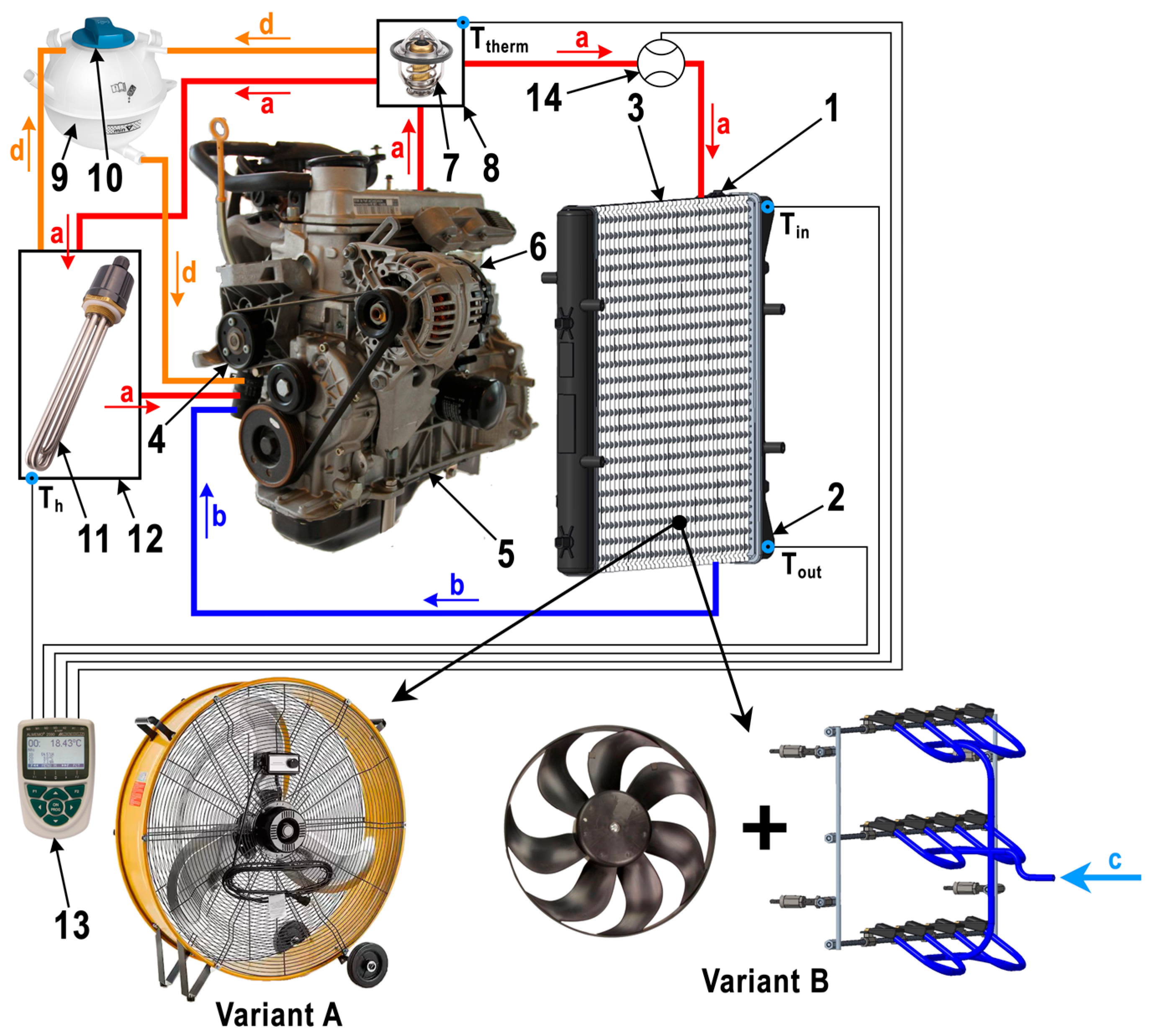
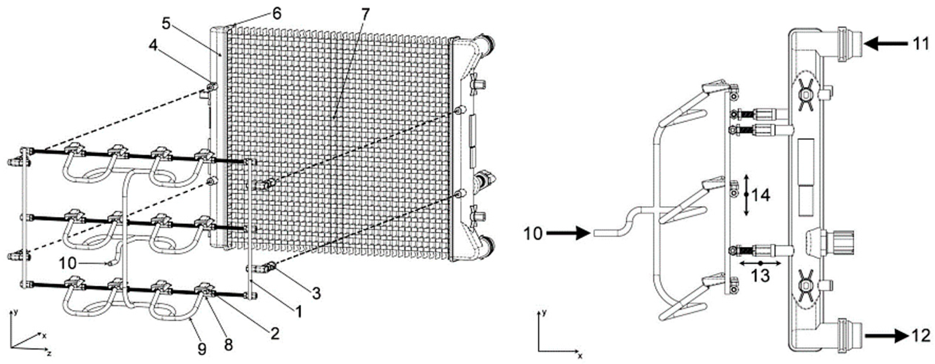
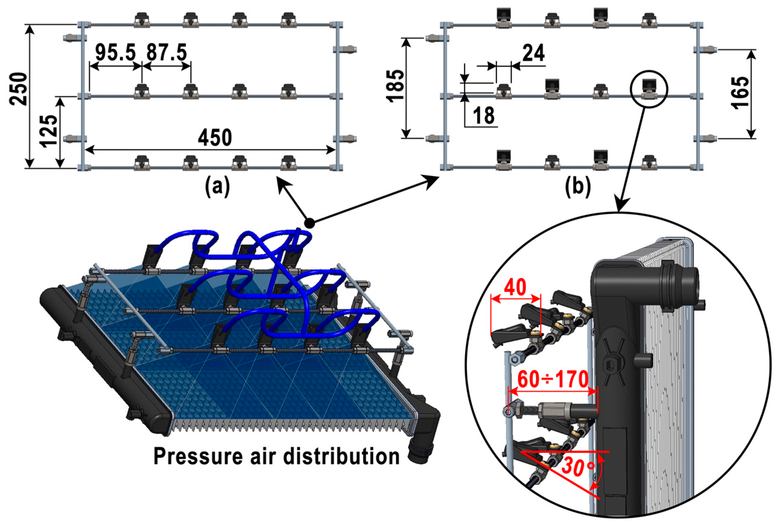
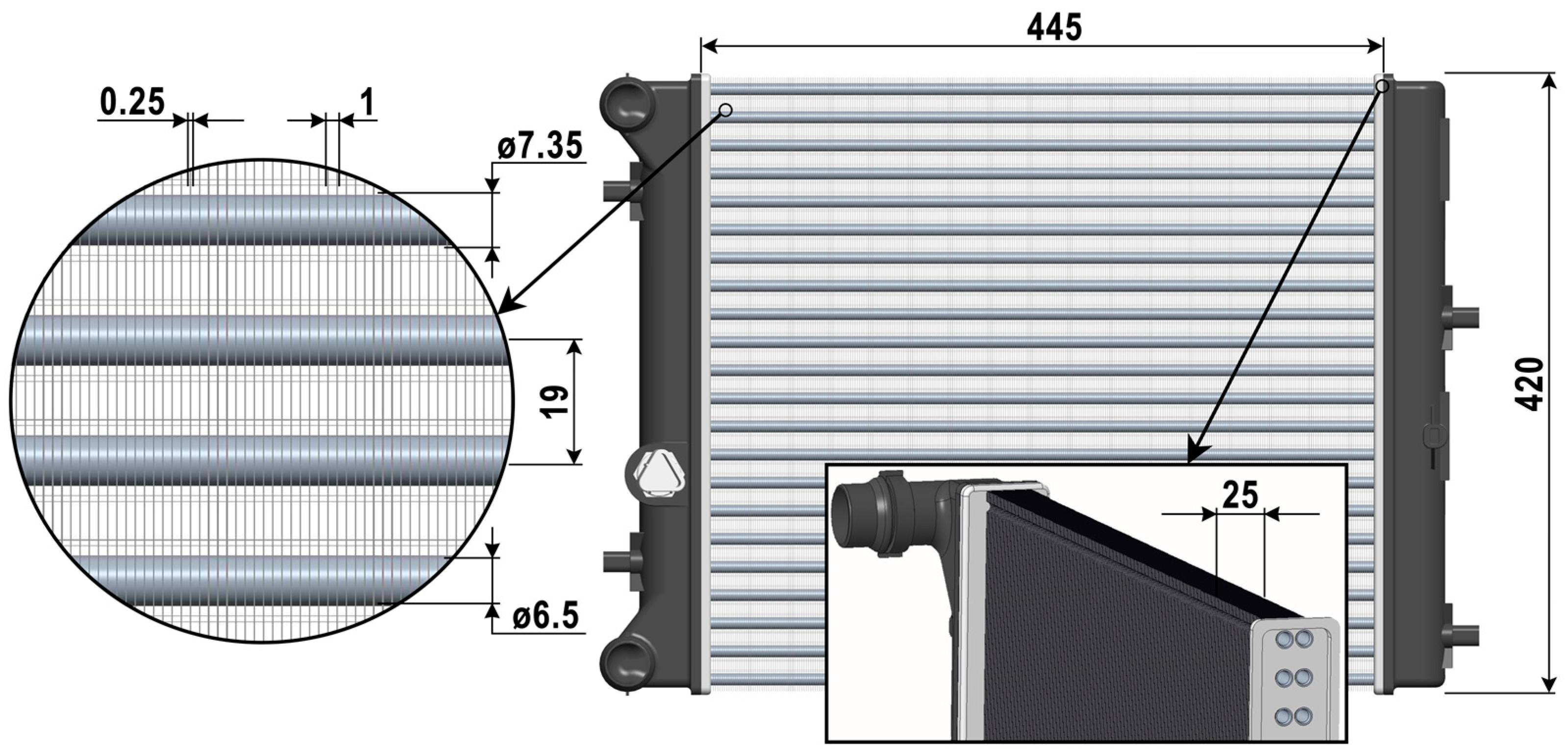
2. Materials and Methods

Experimental research aimed at monitoring the process of forced cooling of hot coolant by additional devices designed for additional heat dissipation from the heat exchange surface of the engine cooler was carried out in order to prevent the failure of power unit components due to thermal stress. When the car is moving, excess heat is extracted by the ambient air flowing through the cooler’s core (heat exchange surface). To simulate this operating condition under laboratory conditions, an industrial axial fan was first mounted in front of the cooler to generate the forced air. Long-term operation of vehicles in the outdoor environment leads to fouling, deformation, and material degradation of the external heat exchange surface of the cooler due to the action of ambient dirt, which leads to a reduction in cooling efficiency and an increased risk of component failure. The second attachment used was a set of air pressure nozzles mounted in front of the cooler. The main function of the air pressure nozzle system is to remove excess heat from the cooler tubes and fins by means of high air pressure (6 bar). At the same time, the high air pressure provides a self-cleaning capability of the heat exchange surface, which prevents premature failure of the component due to the aforementioned impurities from the surrounding environment. Both of these additional cooling devices were fitted into the experimental cooling circuit of the car engine shown in Figure 1. The experimental setup of the car engine cooling circuit reflects the real cooling circuit of the vehicle. It consists of two cooling circuits (small and large) divided by a thermostatic valve (80 °C) but is adapted to laboratory conditions. The total coolant volume is 6 L. The main components, sensors of physical quantities, and operation principle are shown in Figure 1.
Filling of the cooling circuit with coolant (type G12+) is carried out through the expansion tank (9). After that, the water pump (4) is started, which pushes the coolant through the cooling channels in the cylinder block (5) and the cylinder head (6) further into the entire cooling circuit. The experimental research simulates engine operation at no-load speed in the range from 800 to 900 RPM (vehicle driving in a traffic jam), when excess heat accumulation occurs in the engine compartment due to insufficient ambient airflow, which can lead to damage to the integrity of the cooling circuit or to failure of the powertrain functionality. The experimental cooling system setup has (as in the real engine cooling circuit) has two cooling circuits—a short and a long one. Coolant flows in the short cooling circuit only when the temperature is below 80 °C. The short cooling circuit consists of a water pump (4), cylinder block (5), cylinder head (6), thermostatic valve (7), and heater (12). The coolant is heated to operating temperature in the heater (12) by means of a heating coil (11) with a power of 1500 W. In the event of a vent or pressure surge in the heater (12), a vent pipe is connected to the upper wall of the heater (12) and drains into the expansion tank (9). When the coolant reaches a temperature of 80 °C, the thermostatic valve (7) opens, and hot liquid flows into the cooler inlet pipe (1). If hot coolant does not flow under pressure through the cooler tubes (3), some of it flows through the reverse line to the expansion tank (9). Subsequently, the hot coolant (over 80 °C) in the engine cooler (3) is successively cooled in the experimental measurements, first by an external industrial fan, the original 345 mm diameter manufacturer-fitted engine cooler fan (1530 RPM), and a set of air pressure nozzles. A couple of used fans with electric motors generates the necessary cooling airflow by rotating the blades. In the case of the air pressure nozzle system, the cooling airflow is generated by 12 V compressors that fill the supply tanks with pressurized air. The necessary volume and outlet pressure is regulated by a control valve, from where it flows to the outlets of the cooling nozzles. Then, the pressurized air flowing from the outlets of the cooling nozzles disperses the accumulated hot air from the space of the fins and tubes of the cooler (heat exchange surface) into the surrounding area. In the situation of an increase in thermal stress and the associated risk of failure of any of the power unit components, the cooling air outlet pressure can be regulated between 2 and 14 bar depending on the current operating load of the engine. The cooled liquid (below 80 °C) flows through the cooler outlet pipe (2) back to the water pump (4) and from there back to the short cooling circuit until the temperature drops below 80 °C and the thermostatic valve (7) closes.
Temperature and mass flow sensors are part of the experimental setup (Figure 1). The cooler coolant flow temperatures are captured in the cooler inlet pipe (Ti) and the cooler outlet pipe (To) before the thermostatic valve (Ttherm) and in the heater (Th). NTC ZA9040-FS thermistors (Murata Manufacturing, Kyoto, Japan) with a measurement range from −50 °C to 125 °C and an accuracy of ±0.01 °C are used for this purpose. The FVA 915VTH flowmeter (Ahlborn Mess- und Regelungstechnik GmbH, Holzkirchen, Germany) (14) with a measuring range from 2 l/min to 40 l/min and an accuracy of ±1% is installed in the pipe connecting the thermostatic valve (7) and the cooler inlet pipe (1). Measured values are recorded in ALMEMO 2590-4S (Ahlborn Mess- und Regelungstechnik GmbH, Holzkirchen, Germany) value records. The main components of the air nozzle system mounted on the car engine cooler are shown in Figure 2. Cooling of external heat exchange surfaces of coolers by air pressure nozzles is especially suitable for personal, truck, and special motor vehicles or motorcycles. It can also be used in diesel generators and various types of heat exchangers applied in such industries where it is necessary to eliminate overheating of processing fluids to maintain the required constant operating temperature and high heat removal efficiency.
The support bracket (1) consisting of screw rods is used to mount the 12 air pressure nozzles (2). Each air pressure nozzle is mounted to the support bracket by a guide sleeve (8) into which it is screwed. The car cooler (6) has installation holes (4) in its front part for mounting. Adjusting screws (3) are screwed into the cooler installation holes or into the cooler side covers (5) and screwed into the support bracket, thus fixing the system firmly in place. The support bracket (1) can be adjusted relative to the heat exchange surface (7) so that it precisely tracks the surface thereof, thus providing better coverage by cooling air from the air pressure nozzles (2). The individual air pressure nozzles are joined to each other by air hoses (9) of equal length to ensure a constant outlet pressure. Depending on the car cooler, the number of air pressure nozzles and their distance from the heat exchange surface can be varied depending on the varying dimensions of this surface. The air pressure nozzles can be adjusted in different axes (13, 14). The hot coolant enters the engine cooler (11) and flows across the heat exchange surface (7) composed of tubes and fins. The heat exchange surface initially transfers the excess heat to the surrounding area by free convection, and, if the operating temperature of the coolant is exceeded, compressed air from the air tank (10) is transported by the pressurized air supply. The compressed air removes excess heat from the cooler’s tubes and fins, reducing the temperature of the hot coolant passing inside the cooler. The hot coolant flowing into the cooler continuously pressurizes the cooled coolant out of the tubes.
By mounting the air pressure nozzle cooling system on the cooler, conditions are created for reducing the temperature in the cooling circuits when the operating temperature exceeds the required value. The other function of the air pressure nozzle system is to ensure constant purity of the external heat exchange surfaces without the necessity of shutting down machines and equipment and without the necessity of disassembling the cooler. The distribution of pressurized air from the outlets of the air nozzles to the heat exchange surface of the engine cooler, as well as the basic dimensions of the air nozzle system and their arrangement, are shown in Figure 3. The experiments used a row arrangement of nozzles perpendicular to the heat sink (Figure 3a) and a staggered arrangement (two nozzles in one row perpendicular and two nozzles rotated by 30° with respect to the heat exchange surface in an offset arc) (Figure 3b).
An industrial axial fan (simulating the driving of a vehicle in a traffic jam—cooling air surge), a factory fan with an electric motor, and a system of pressure nozzles removed excess heat from the external heat exchange surface of the engine cooler, intended for gasoline engine versions originating from the Skoda Fabia (Skoda Auto, a.s., Mladá Boleslav, Czech Republic) model (Figure 4). The engine cooler consists of 44 aluminum circular tubes with an internal diameter of ø 6.5 mm and an external diameter of ø 7.35 mm, in which the coolant flows in two rows in succession. Along the entire height of the cooler, 400 aluminum ribs are firmly attached to the tubes for more intensive heat dissipation. Each rib is 0.25 mm thick and 25 mm wide. The spacing between the cooler fins is 1 mm. The vertical distance between the pipes is 19 mm, and the distance between the first and second rows is 10 mm.

3. Results and Discussion

In order to determine the cooling efficiency of the external heat exchange surfaces of the cooler by air nozzles, a series of experimental measurements were carried out. First, the effect of the forced air from the external fan on the cooling time of the G12+ coolant and the effect of the fan cooler (without nozzles) were investigated, and these were compared with each other. For comparison, measurements were carried out with the cooler fan mounted on the cooler. Subsequently, the air nozzles were placed inline and staggered in front of the cooler at distances ranging from 60 mm to 170 mm in combination with the cooler fan and compared with the cooling time of the single cooler fan. The coolant was initially heated until time 45 min and 30 s, when the thermostat rated at 80 °C was opened and the coolant flow rate was 2.6 m3/h. From this time onwards, the inlet and outlet temperatures of the cooler were recorded, and the cooling time was recorded. When using an external fan, the cooling time was 180 s; when using air nozzles, it was important to record temperatures for 90 s.

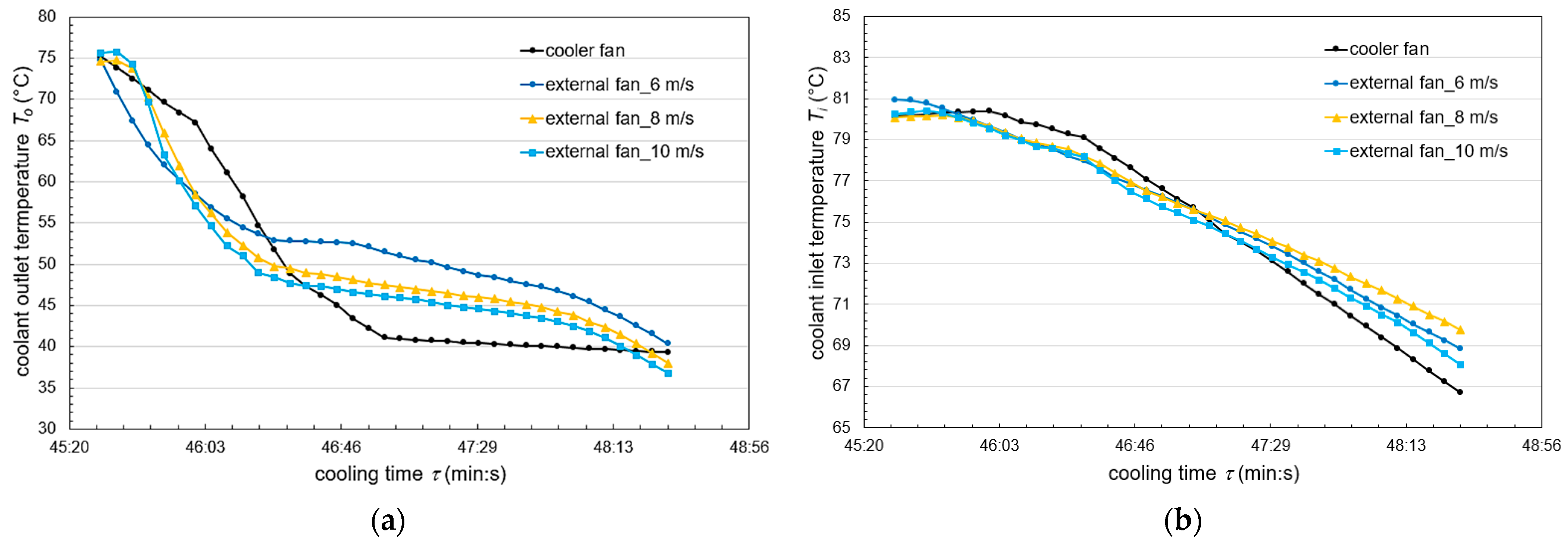
3.1. Comparison of Engine Cooler Cooling by the Cooler Fan and External Fan by Forced Air (Variant B)

As the car drives, the airflow impacts the front of the car and reaches the pipes and fins of the engine cooler, cools the coolant circulating in the cooler, and cools the engine components. In the case of a correctly functioning car cooling circuit, the electric fan located on the engine cooler is rarely activated. This is due to the fact that the airflow generated by the movement of the car removes excess heat from the heat exchange surfaces of the cooler fast enough. In our experimental measurements, the forced air on the cooler was generated by an external Master DF 20 P fan located in front of the cooler. Thus, the motion of the car was simulated in the laboratory conditions. The above-mentioned external fan was an industrial axial drum fan, sized to suit the engine cooler under investigation and providing airflow distribution and circulation of 6600 m3/h at an outer diameter of 500 mm. The airflow velocity was varied in three velocity levels (1st level: 6 m/s, 2nd level: 8 m/s, 3rd level: 10 m/s). During the cooling of the cooler by the forced air (external fan), the coolant temperatures at the inlet to the cooler (Figure 5b) and the outlet of the cooler (Figure 5a) were recorded as the air velocity was changed. For comparison, the mentioned temperatures were also recorded when cooling by the cooler fan, which was placed directly on the cooler (Figure 1). Cooling by fans (external fan and cooler fan) started at the same time of 45 min and 30 s, because until this time the coolant was heated to a temperature above 80 °C, when the thermostat was fully opened and the coolant was released into the cooler.
From the temperature distribution at the inlet of the cooler Ti (Figure 5b), it is clear that the cooling by the external fan at the tested velocities is more efficient at 45:50 to 47:05 compared to the cooler fan. Subsequently, from the time 47:05 to 48:30, the Ti temperature decreased more significantly for the cooler fan, which at the end of cooling represented a decrease of 1.36 °C to 3.04 °C compared to the external fan for velocities of 6, 8, and 10 m/s. This is due to the fact that the blast air from the external fan passing through the cooler impacts the plastic cooler fan cover, which blocks the blast air from cooled components of the cooling system and the engine. The only possible airflow path is through the fan blades on the cooler, but this reduces the heat dissipation from the components behind the cooler. However, this problem does not occur with the cooler fan because it initially sucks in hot air from the front of the cooler and exhausts it into the engine compartment, whose temperature decreases at the same time. From the point of view of real engine operation, the measured difference in inlet temperatures Ti when operating with an external fan and a fan cooler is negligible, because the temperature drop during cooling is usually below the operating temperature and the cooling process only takes a few seconds.
From the temperature distribution at the outlet of the cooler To (Figure 5a), it can be seen that the temperature decreases with increasing velocity of forced air from the external fan from 6 m/s to 10 m/s, which means that the heat dissipation during the cooling process is more intense. Intensified cooling of the coolant increases the efficiency of engine operation and therefore the engine lifecycle. Also, in this case, cooling by the fan on the cooler was more efficient only in a time range from 46:40 to 48:15.
For the coolant outlet temperature, the correlating equation was created in the form of a two-term Gaussian function, where the coefficients were determined by the least square method with the percentage standard deviation of the error ESD = 1.14% and the error E ranged from −2.35% to 3.45%:
T o = a 0 v + a 1 exp a 2 + a 3 v + τ a 4 v + a 5 2 + b 0 v + b 1 exp b 2 + b 3 v + τ b 4 v + b 5 2
T o = 0.64 v + 25.82 exp 1.83 + 0.007 v + τ 0.94 v + 40.83 2 + 0.99 v + 56.64 exp 84.37 + 1.7 v + τ 3.21 v + 210.28 2
For the coolant inlet temperature, the correlating equation was created in the form of a two-term exponential function, where the coefficients were determined by the least square method with the percentage standard deviation of the error ESD = 0.49% and the error E ranged from −1.45% to 0.99%:
T i = a 0 exp a 1 τ + b 0 exp b 1 τ
T i = 85.63 exp 0.0012 τ 5.03 exp 0.0165 τ
The correctness of the correlating equations for To and Ti is shown in Figure 6.

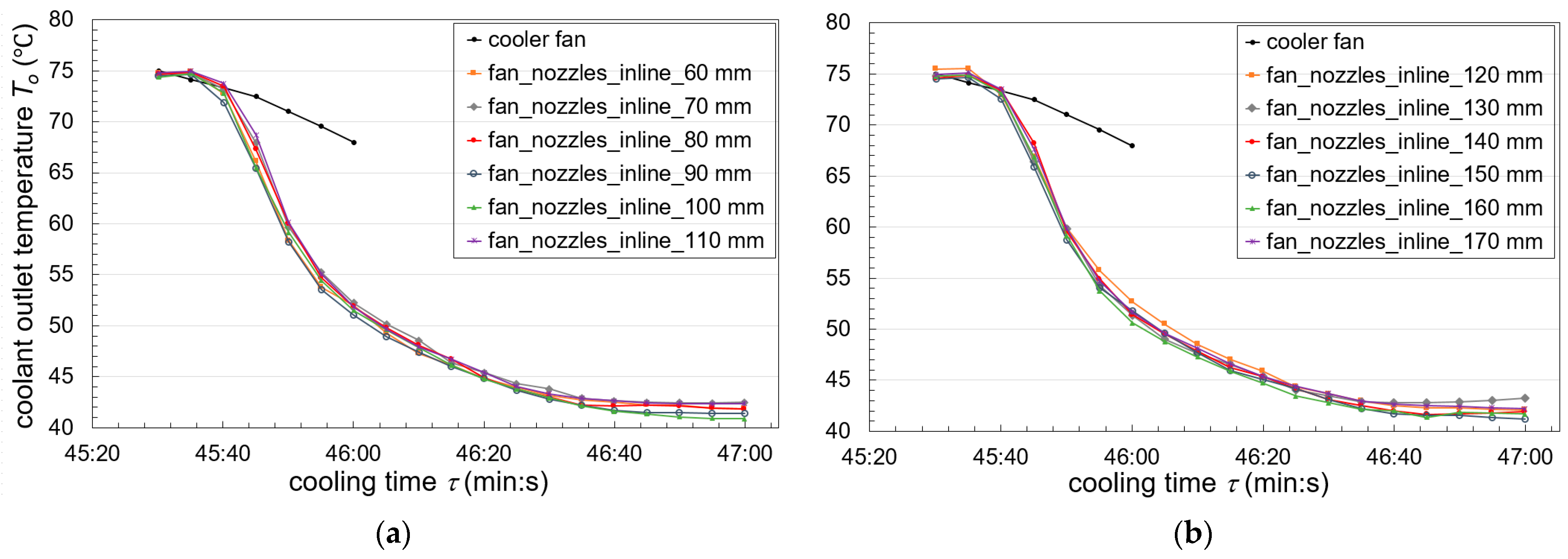
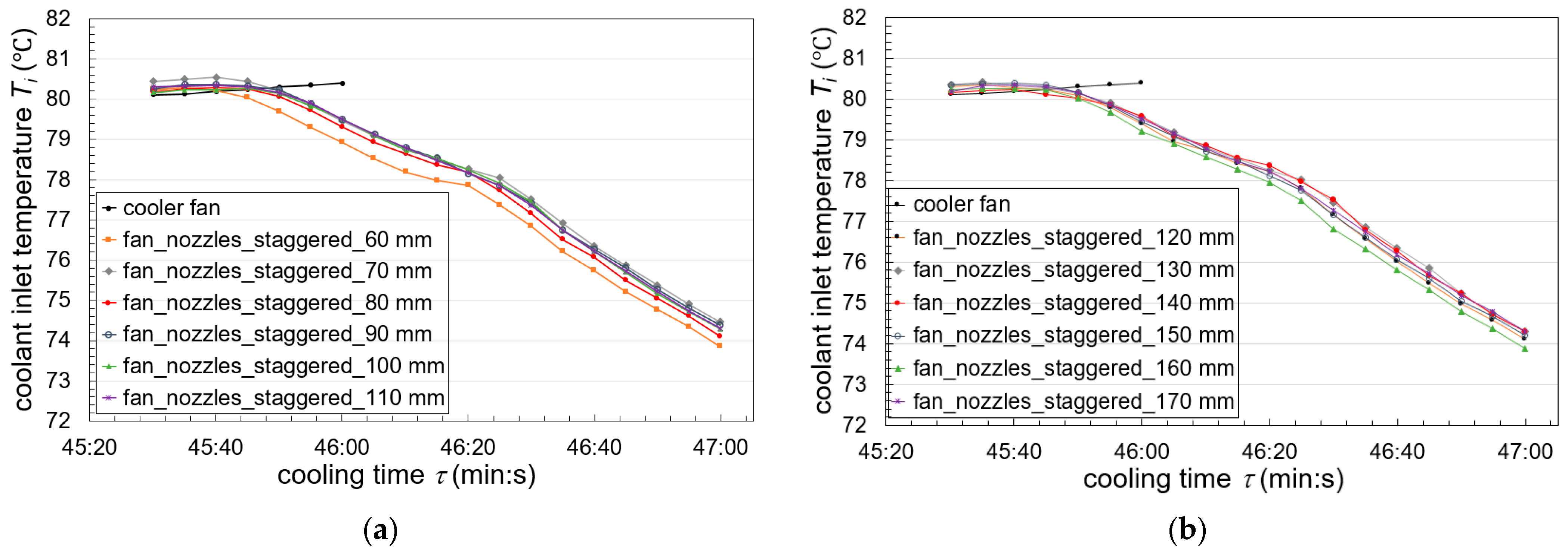
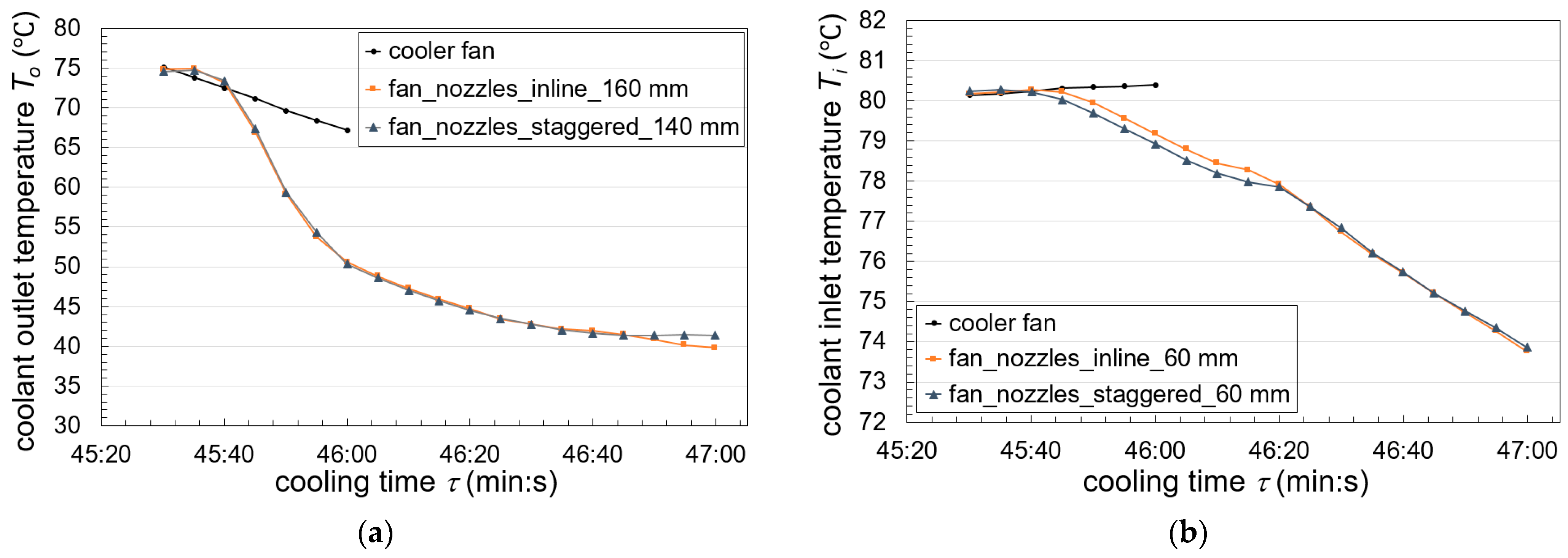
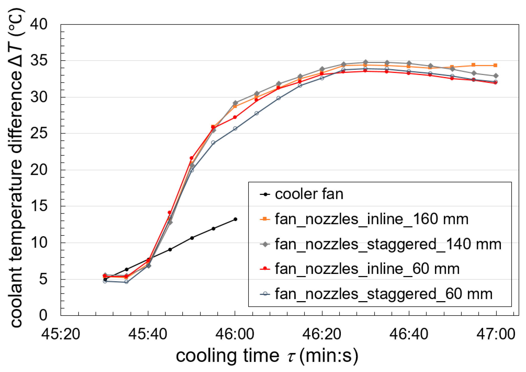
3.2. Comparison of Engine Cooler Cooling by the Cooler Fan and Its Combination with Air Pressure Nozzles (Variant B)

The coolant cooling distribution for the inline nozzle and cooler fan configuration was recorded by coolant outlet temperature To, as the nozzle to cooler distance was varied from 60 mm to 170 mm (Figure 7). A series of measurements were performed, and the observed cooling time was identical for all cases studied, ranging from 45 min and 30 s to 47 min. The air pressure at the outlet of the air nozzles was a constant 6 bar. The temperatures using the nozzles and the cooler fan and the single cooler fan were compared with each other. The graphical distributions show that cooling the coolant with nozzles and the cooler fan causes an increase in the cooling efficiency compared to a single cooler fan. In a time of 46 min, the nozzles and the cooler fan achieved a decrease in coolant outlet temperature of 0.76 to 1.02 times compared to cooling by the single cooler fan. The earlier the To is decreased, the more intense the heat dissipation process and the more efficient the engine cooling. At a time of 47 min, the difference between the maximum and minimum outlet temperature of the coolant To was 2.36 °C. A maximum nozzle to cooler distance of 170 mm was investigated due to the space capabilities of the vehicles in front of the cooler; also, the cooling efficiency decreased from a distance of 160 mm.
The coolant cooling distribution for the inline nozzle and cooler fan configuration was recorded by coolant inlet temperature Ti, as the nozzle to cooler distance was varied from 60 mm to 170 mm (Figure 8). In a time of 46 min, the nozzles and cooler fan achieved a decrease in the inlet temperature of the coolant Ti ranging from 0.98 to 1.00 times compared to cooling by the single cooler fan. At 47 min, the difference between the maximum and minimum inlet temperature of the coolant Ti was 0.46 °C, indicating that the effect of varying the distance of the nozzles from the cooler is not very significant.
For the coolant outlet temperature, the correlating equation was created in the form of a rational function, where the coefficients were determined by the least square method with the percentage standard deviation of the error ESD = 1.77% and the error E ranged from −4.39% to 4.04%:
T o = a 0 a 1 + a 2 τ 3 + a 4
T o = 274.6 8.26 + 0.0008 τ 3 + 41.82
For the coolant inlet temperature, the correlating equation was created in the form of a one-term Fourier function, where the coefficients were determined by the least square method with the percentage standard deviation of the error ESD = 0.22% and the error E ranged from −0.56% to 0.42%:
T i = a 0 + a 1 cos a 2 τ + a 3 sin a 2 τ
T i = 75.62 + 4.69 cos 0.022 τ + 0.16 sin 0.022 τ
The coolant cooling distribution for the staggered nozzle and cooler fan configuration was recorded by outlet temperature To, as the distance between the nozzles and the cooler was varied from 60 mm to 170 mm (Figure 9). In a time of 46 min, the nozzles and the cooler fan achieved a decrease in coolant outlet temperature of 0.78 to 1.03 times compared to cooling by the single cooler fan. At a time of 47 min, the difference between the maximum and minimum coolant outlet temperature of To was 1.32 °C, which is 1.04 °C less compared to the inline arrangement.
The coolant cooling distribution for the staggered nozzle and cooler fan configuration was recorded by inlet temperature Ti while varying the distance of the nozzles from the cooler from 60 mm to 170 mm (Figure 10). In a time of 46 min, the nozzles and cooler fan achieved a decrease in the inlet temperature of the coolant Ti range of 0.98 to 1.01 times compared to cooling by the single cooler fan. At a time of 47 min, the difference between the maximum and minimum inlet coolant temperature Ti was 0.61, which is 0.15 more compared to the inline arrangement.
For the coolant outlet temperature, the correlating equation was created in the form of a rational function, where the coefficients were determined by the least square method with the percentage standard deviation of the error ESD = 1.79% and the error E ranged from −5.76% to 5.19%:
T o = a 0 a 1 + a 2 τ 3 + a 4
T o = 272.6 8.14 + 0.00076 τ 3 + 41.69
For the coolant inlet temperature, the correlating equation was created in the form of a one-term Fourier function, where the coefficients were determined by the least square method with the percentage standard deviation of the error ESD = 0.27% and the error E ranged from −0.72% to 0.78%:
T i = a 0 + a 1 cos a 2 τ + a 3 sin a 2 τ
T i = 75.39 + 4.95 cos 0.021 τ + 0.1 sin 0.021 τ
Table 1 compares the inlet and outlet temperatures for the three configurations studied at cooling times of 46 and 47 min, or 30 s and 90 s from the start of the cooling process. The coolant outlet temperature To was higher by up to 26.03 °C and 26.22 °C at 47 min when using a single cooler fan compared to the inline and cooler fan and staggered and cooler fan configurations, respectively. The inlet temperature of the coolant Ti when using a single cooler fan was higher by 6.33 °C and 6.18 °C at 47 min compared to the inline and cooler fan and staggered and cooler fan configurations, respectively.
Mutual comparison of the inline and staggered arrangements at 46 min and 47 min showed only minimal differences for the average of all examined distances. It has been confirmed that the air pressure nozzle system with a cooler fan significantly supports heat dissipation from the cooler, but the nozzle arrangement (inline, staggered) does not have a significant effect on the cooling process.
The single cooler fan, by rotating the blades, does not distribute the air evenly over the entire heat exchange surface and cannot press the air intensively through the external surfaces of the tubes and fins of the cooler. On the contrary, the air pressure nozzle system evenly covers the entire heat exchange surface with air and the generated air pressure flows around the tubes and fins more intensively, which results in faster heat dissipation. When using a cooler with two rows of tubes, it is necessary that the second row of tubes also cools the air, not just the first row. This is not sufficient when using only a cooler fan, so air pressure nozzles have greatly supplemented the overall cooling process. By covering the entire heat exchange surface with air from the nozzles, there is no heat accumulation, especially in the peripheral zones of the cooler, as in the case of cooling by a single cooler fan. This has a positive effect on the efficiency and economic operation of the engine.
In a time of 46 min, the lowest coolant outlet temperature To = 50.59 °C was achieved using an inline nozzle and cooler fan configuration (d = 160 mm). Using a staggered nozzle arrangement with the cooler fan, the lowest cooler outlet temperature To = 50.36 °C was achieved at a nozzle to cooler distance of 140 mm (Figure 11a). When the inlet coolant temperature Ti was evaluated at 46 min, the lowest values were obtained at a nozzle to cooler distance d = 60 mm for both the inline arrangement (Ti = 79.18 °C) and the staggered arrangement (Ti = 78.93 °C) (Figure 11b). The nozzle arrangement (inline, staggered) had no significant effect on the inlet and outlet coolant temperatures during the cooling process.
However, when comparing the single cooler fan and the nozzle system with the cooler fan at 46 min, a decrease of 24.7% (inline, d = 160 mm) and 25.0% (staggered, d = 140 mm) in the coolant outlet temperature To was achieved, showing an advantage of the nozzle system with the cooler fan. For coolant inlet temperatures Ti, there was a 1.5% (inline, d = 60 mm) and 1.8% (staggered, d = 60 mm) temperature decrease, showing an advantage of the nozzle system with the cooler fan.
A comparison of the temperature differences for the most efficient configurations compared to a single cooler fan is shown in Figure 12. The inline nozzle system (d = 160 mm) with the cooler fan achieved the highest temperature differences during the entire cooling time, ranging from ΔT = 5.36 °C to 34.31 °C, and the staggered nozzle system (d = 140 mm) with the cooler fan ranged from ΔT = 5.58 °C to 32.90 °C. The higher temperature difference represents a more intensive heat dissipation by the cooler. At nozzle distances of 140 mm to 160 mm, a large surface area of the cooler is covered by the air stream compared to nozzles at 60 mm; therefore, heat dissipation by the cooler also increases as the distance of the nozzles from the cooler increases. The correctness of the correlating equations for To and Ti is shown in Figure 13.

3.3. Practical Application and Advantages of the Pneumatic Nozzle System

Air chassis operating with compressed air at high pressure are increasingly being installed (also, additionally) in modern vehicles. The air suspension can have an open or closed system. In an open system, the compressor sucks in air from the surroundings and, when compressed, supplies it to the springs, while the used air is exhausted to the surroundings (utility vehicles and buses). The most commonly used is a closed system (our case), which also contains an air reservoir. The pneumatic system designed and investigated by us can be used as both a source and a supply of air for pressure nozzles mounted directly in vehicles.
If the vehicle is not equipped with a pneumatic circuit, there are several options for adding one. If space permits, the most ideal mounting location is on the frame or underbody of the vehicle. The disadvantage of this solution is that if the components are mounted in exposed locations or are subject to surface abrasion from gravel bouncing off the wheels of the vehicle, microcracks may form and result in undesirable pressure air leakage in the future.
Another solution is to place the pneumatic circuit assembly in the luggage compartment, specifically under its double bottom or in the spare wheel compartment. A support board with a set of compressors and pressure vessels would form the floor of the lower part of the luggage compartment. The pneumatic circuit would thus be comprehensively protected against weather influences and mechanical damage from the exterior, thus ensuring long-term, trouble-free operation. The only exposed part would be the plastic packaging of the filter cartridges, through which purified air from the ambient environment is drawn into the compressors.
The least appropriate solution and the most complicated is to place the pneumatic circuit in the engine compartment. In most cases, such a solution will not be possible in terms of dimensional parameters. On the other hand, even in the case of free space around the engine, it is not advisable to place additional compressors and pressure vessels due to the complications of regular servicing operations, disruption of continuous heat dissipation from the engine compartment, or thermal stress of individual elements of the pneumatic circuit from the hot engine.
Advantages of the pneumatic nozzle system:
-
pressure nozzles allow more efficient heat dissipation from the cooler to the surroundings,
-
a more uniform airflow over the entire heat exchange surface is achieved compared to the conventional cooler fan; no hotspots are created,
-
reduction of the total weight of the cooling circuit, if the vehicle is equipped with a compressed air supply,
-
reduction of noise from the rotating blades of conventional cooler fans,
-
self-cleaning ability of the outer surfaces of the cooler fins and tubes, which become clogged with impurities during vehicle operation (dust, gravel, sand, feathers, salt, flies, etc.) and thus reduce the efficiency of the cooling process,
-
the possibility to use in combination with fans for more efficient cooling process and overall heat transfer (prevention of clogging of heat exchanger surfaces).

4. Conclusions

Cooling of the G12+ coolant by the external fan caused a gradual decrease in the outlet temperature of the coolant To as the air velocity increased from 6 m/s to 10 m/s (Variant A). This results in more intense heat dissipation and therefore more efficient cooling of the coolant, thus improving operating conditions and engine lifecycle. Subsequently, instead of the external fan, a set of 12 air pressure nozzles was mounted in front of the cooler in order to cool and purify the tubes and fins of the cooler (Variant B). Results show that cooling the coolant with nozzles and the cooler fan simultaneously causes an increase in the cooling efficiency compared to a single cooler fan. The results of the comparison of the cooling process by an air pressure nozzle system and a single cooler fan can be summarized as follows:
-
The inline nozzles arrangement with the cooler fan achieved a decrease in To of 0.76 to 1.02 times and Ti of 0.98 to 1.00 times compared to cooling by the single cooler fan, respectively;
-
The staggered nozzle arrangement with the cooler fan achieved a decrease in To of 0.78 to 1.03 times and Ti of 0.98 to 1.01 times compared to cooling by the single cooler fan, respectively;
-
The earlier the To is decreased, the more intense the heat dissipation process and the more efficient the engine cooling;
-
When considering the temperature differences at the inlet and outlet of the cooler, the To was higher by up to 26.03 °C and 26.22 °C when using a single cooler fan compared to the inline nozzles and cooler fan and staggered nozzles and cooler fan configurations, respectively;
-
Changing the distance of the nozzles from the cooler has the effect of decreasing the inlet and outlet temperatures of the cooler while cooling it. The nozzles reduced the cooler outlet temperatures, with a difference between the maximum and minimum To values of, on average, 1.6 °C and 1.87 °C, and between the maximum and minimum Ti values of, on average, 0.43 °C and 0.56 °C during the cooling process for the inline and staggered configurations, respectively;
-
The higher temperature difference represents a more intensive heat dissipation by the cooler;
-
The system of air pressure nozzles in combination with the cooler fan (Variant B) causes an improvement in the cooling process compared to a single cooler fan.
The air pressure nozzle system evenly covers the entire heat exchange surface with air and the generated air pressure flows around the tubes and fins more intensively, also in the case of double-row and multi-row tubular heat exchangers. This is not sufficient when using the single cooler fan, so air pressure nozzles have greatly supplemented the overall cooling process. By covering the entire heat exchange surface with air from the nozzles, there is no heat accumulation, especially in the peripheral zones of the cooler, as in the case of cooling by a single cooler fan. This has a positive effect on the efficiency and economic operation of the engine. The air pressure nozzle system can be used if the efficiency of the original heat exchanger has decreased due to long-term operation. It is also effective when the performance of an automobile, machine, or equipment needs to be increased where excessive heat is generated and the design dimensions do not allow the use of a dimensionally larger cooler or fan. If the operating conditions of machinery and equipment are subject to pollution from the weather and constant fouling of external heat exchange surfaces, air pressure nozzles contribute to the elimination of this undesirable effect. In the case of supplementing an air pressure nozzle system to a machine or equipment from a manufacturer equipped with a pneumatic circuit (e.g., a brake circuit), the installation of such a system is fast, efficient, and economically inexpensive.

Author Contributions

Conceptualization, M.L. and Z.B.; methodology, M.L. and Z.B.; software, S.K. and P.B.; validation, Z.B. and S.K.; formal analysis, Z.B.; investigation, M.L. and Z.B.; resources, M.L.; data curation, Z.B.; writing—original draft preparation, Z.B. and M.L.; writing—review and editing, Z.B. and M.L.; supervision, Z.B.; project administration, M.L. All authors have read and agreed to the published version of the manuscript.

Funding

This research was funded by the EU NextGenerationEU through the Recovery and Resilience Plan for Slovakia under project No. 09I03-03-V05-00016, “Investigation of Innovative Approaches to Cooling the External Heat Exchange Surfaces of Automotive Coolers”.

Data Availability Statement

The raw data supporting the conclusions of this article will be made available by the authors on request.

Conflicts of Interest

The authors declare no conflicts of interest.

Abbreviations

The following abbreviations are used in this manuscript:
ddistance between the cooler and nozzles (mm)
ΔTtemperature difference (°C)
G12+type of the coolant
Thtemperature in the heater (°C)
Titemperature in the inlet pipe of the cooler (°C)
Totemperature in the outlet pipe of the cooler (°C)
Tthermtemperature in the thermostatic valve (°C)
τcooling time (min:s)

References

  1. Che Sidik, N.A.; Witri Mohd Yazid, M.N.A.; Mamat, R. Recent advancement of nanofluids in engine cooling system. Renew. Sustain. Energy Rev. 2017, 75, 137–144. [Google Scholar] [CrossRef]
  2. Bigdeli, M.B.; Fasano, M.; Cardellini, A. A review on the heat and mass transfer phenomena in nanofluid coolants with special focus on automotive applications. Renew. Sustain. Energy Rev. 2016, 60, 1615–1633. [Google Scholar] [CrossRef]
  3. Leong, K.Y.; Saidur, R.; Kazi, S.N.; Hamun, A.H. Performance investigation of an automotive car radiator operated with nanofluid-based coolants (nanofluid as a coolant in a radiator). Appl. Therm. Eng. 2010, 30, 2685–2692. [Google Scholar] [CrossRef]
  4. Chen, X.; Yu, X.; Lu, Y.; Huang, R.; Liu, Z.; Huang, Y.; Roskilly, A.P. Study of different cooling structures on the thermal status of an Internal Combustion Engine. Appl. Therm. Eng. 2017, 116, 419–432. [Google Scholar] [CrossRef]
  5. Fontanesi, S.; Giacopini, M. Multiphase CFD–CHT optimization of the cooling jacket and FEM analysis of the engine head of a V6 diesel engine. Appl. Therm. Eng. 2013, 52, 293–303. [Google Scholar] [CrossRef]
  6. Mukkamala, Y. Contemporary trends in thermo-hydraulic testing and modeling of automotive radiators deploying nano-coolants and aerodynamically efficient air-side fins. Renew. Sustain. Energy Rev. 2017, 76, 1208–1229. [Google Scholar] [CrossRef]
  7. Pang, S.C.; Kalam, M.A.; Masjuki, H.H.; Hazrat, M.A. A review on air flow and coolant flow circuit in vehicles’ cooling system. Int. J. Heat Mass Transf. 2012, 55, 6295–6306. [Google Scholar] [CrossRef]
  8. Cipollone, R.; Battista, D.; Gualtieri, A. A novel engine cooling system with two circuits operating at different temperatures. Energy Conv. Manag. 2013, 75, 581–592. [Google Scholar] [CrossRef]
  9. Cipollone, R.; Battista, D. Sliding vane rotary pump in engine cooling system for automotive sector. Appl. Therm. Eng. 2015, 76, 157–166. [Google Scholar] [CrossRef]
  10. Chastain, J.; Wagner, J.; Eberth, J. Advanced engine cooling–Components, testing and observations. IFAC Proc. Vol. 2010, 43, 294–299. [Google Scholar] [CrossRef]
  11. Said, Z.; Assad, M.E.H.; Hachicha, A.A.; Bellos, E.; Abdelkareem, M.A.; Alazaizeh, D.Z.; Bashria, A.A. Enhancing the performance of automotive radiators using nanofluids. Renew. Sustain. Energy Rev. 2019, 112, 183–194. [Google Scholar] [CrossRef]
  12. Mohamed, E.S. Development and analysis of a variable position thermostat for smart cooling system of a light duty diesel vehicles and engine emissions assessment during NEDC. Appl. Therm. Eng. 2016, 99, 358–372. [Google Scholar] [CrossRef]
  13. Haghighat, A.K.; Roumi, S.; Madani, N.; Bahmanpour, D.; Olsen, M.G. An intelligent cooling system and control model for improved engine thermal management. Appl. Therm. Eng. 2018, 128, 253–263. [Google Scholar] [CrossRef]
  14. Subhedar, D.G.; Ramani, B.M.; Gupta, A. Experimental investigation of heat transfer potential of Al2O3/Water-Mono Ethylene Glycol nanofluids as a car radiator coolant. Case Stud. Therm. Eng. 2018, 11, 26–34. [Google Scholar] [CrossRef]
  15. Kulkarni, D.P.; Vajjha, R.S.; Das, D.K.; Oliva, D. Application of aluminum oxide nanofluids in diesel electric generator as jacket water coolant. Appl. Therm. Eng. 2008, 28, 774–1781. [Google Scholar] [CrossRef]
  16. Arora, N.; Gupta, M. An updated review on application of nanofluids in flat tubes radiators for improving cooling performance. Renew. Sustain. Energy Rev. 2020, 134, 110242. [Google Scholar] [CrossRef]
  17. Park, M.; Lee, D. Sources of broadband noise of an automotive cooling fan. Appl. Acoust. 2017, 118, 66–75. [Google Scholar] [CrossRef]
  18. Krishna, S.R.; Krishna, A.R.; Ramji, K. Reduction of motor fan noise using CFD and CAA simulations. Appl. Acoust. 2011, 72, 982–992. [Google Scholar] [CrossRef]
  19. Rynell, A.; Chevalier, M.; Abom, M.; Efraimsson, G. A numerical study of noise characteristics originating from a shrouded subsonic automotive fan. Appl. Acoust. 2018, 140, 110–121. [Google Scholar] [CrossRef]
  20. Pradhan, P.; Singh, D. Review on air suspension system. Mater. Today Proc. 2023, 81, 486–488. [Google Scholar] [CrossRef]
  21. Zhao, N.; Li, S.; Yang, J. A review on nanofluids: Data-driven modeling of thermalphysical properties and the application in automotive radiator. Renew. Sustain. Energy Rev. 2016, 66, 596–616. [Google Scholar] [CrossRef]
  22. Eskandary, K.P.; Khajepour, A.; Wong, A.; Ansari, A. Analysis and optimization of air suspension system with independent height and stiffness tuning. Int. J. Automot. Technol. 2016, 17, 807–816. [Google Scholar] [CrossRef]
  23. Sun, X.; Cai, Y.; Chen, L.; Liu, Y.; Wang, S. Vehicle height and posture control of the electronic air suspension system using the hybrid system approach. Mobil. Vehicle Mech. 2016, 54, 328–352. [Google Scholar] [CrossRef]
  24. Kim, H.; Lee, H. Height and leveling control of automotive air suspension system using sliding mode approach. IEEE Trans. Veh. 2011, 60, 2027–2041. [Google Scholar]
  25. Rajko, L.; Koleda, P.; Barcik, S.; Koleda, P. Technical and technological factors’ effects on quality of the machined surface and energetic efficiency when planar milling heat-treated meranti wood. BioResources 2021, 16, 7884–7900. [Google Scholar] [CrossRef]
  26. Fang, Y.; Lu, Y.; Yu, X.; Roskilly, A.P. Experimental study of a pneumatic engine with heat supply to improve the overall performance. Appl. Therm. Eng. 2018, 134, 78–85. [Google Scholar] [CrossRef]
  27. Wasbari, F.; Bakar, R.A.; Gan, L.M.; Tahir, M.M.; Yusof, A.A. A review of compressed-air hybrid technology in vehicle system. Renew. Sustain. Energy Rev. 2017, 67, 935–953. [Google Scholar] [CrossRef]
  28. Marvania, D.; Subudhi, S. A comprehensive review on compressed air powered engine. Renew. Sustain. Energy Rev. 2017, 70, 1119–1130. [Google Scholar] [CrossRef]
  29. Fang, Y.; Lu, Y.; Roskilly, A.P.; Yu, X. A review of compressed air energy systems in vehicle transport. Energy Strategy Rev. 2021, 33, 100583. [Google Scholar] [CrossRef]
  30. Wang, X.; Liu, C.; Dong, Q.; Zhao, J.; Lai, C.; Lin, J.; Ji, J.; Liu, M. Numerical simulation of radial duel-stage nozzle vortex cooling at the leading edge of a gas turbine blade. Appl. Therm. Eng. 2025, 260, 125017. [Google Scholar] [CrossRef]
  31. Yang, W.; Sang, X.; Chen, B. Numerical simulation of closed-cycle R410A flash spray cooling with multiple nozzles on a large heat exchange surface. Appl. Therm. Eng. 2025, 268, 125878. [Google Scholar] [CrossRef]
  32. Su, C.-Q.; Wang, S.; Liu, X.; Tao, Q.; Wang, Y.-P. Experimental and numerical investigation on spray cooling of radiator in fuel cell vehicle. Energy Rep. 2022, 8, 1283–1294. [Google Scholar] [CrossRef]
  33. Fordon, A.G.; Soria, F.; Woodruff, E.; Brewer, C.; Xu, Y.; Putnam, S.A. Multi-nozzle, common-rail based, piezo-actuated, pulsed spray cooling testbed. Int. J. Heat Mass Transf. 2025, 241, 126596. [Google Scholar] [CrossRef]
Figure 1. Cooling of the external heat exchange surfaces of the cooler with forced air. 1—cooler inlet pipe, 2—cooler outlet pipe, 3—car cooler, 4—water pump, 5—cylinder block, 6—cylinder head, 7—thermostatic valve, 8—thermostatic valve cover, 9—expansion tank, 10—pressure plug, 11—heating coil, 12—heater, 13—data logger, 14—flowmeter, a—hot coolant (80 °C), b—cooled coolant (below 80 °C), c—cooling airflow (ambient temperature), d—coolant operating temperature, Variant A—external fan, Variant B—cooler fan and air nozzle system.
Processes 13 00582 g001
Figure 2. The components of the air nozzle system mounted on the car engine cooler. 1—support bracket, 2—air pressure nozzle, 3—adjusting screw, 4—installation hole, 5—cooler side cover, 6—car cooler, 7—heat exchange surface, 8—guide sleeve, 9—air hose, 10—pressure air supply, 11—hot coolant inlet, 12—cooled coolant outlet, 13, 14—displacement of nozzles in x, y axis.
Processes 13 00582 g002
Figure 3. Pressure air distribution and arrangement of the air pressure nozzle system in front of the cooler: (a) inline, (b) staggered (dimensions are in mm).
Processes 13 00582 g003
Figure 4. Basic dimensions and arrangement of the pipes and ribs of the Skoda Fabia engine cooler (Skoda Auto, a.s., Mladá Boleslav, Czech Republic) (dimensions are in mm).
Processes 13 00582 g004
Figure 5. Distribution of coolant temperatures for the cooler fan and external fan: (a) coolant inlet temperatures; (b) coolant outlet temperatures.
Processes 13 00582 g005
Figure 6. Comparison between presented correlating equations and experimental results for the external fan: (a) coolant outlet temperature To; (b) coolant inlet temperature Ti.
Processes 13 00582 g006
Figure 7. Distribution of the outlet temperature for combination of the cooler fan and inline arrangement of the air pressure nozzles during cooling of the coolant: (a) nozzle to cooler distance ranging from 60 mm to 110 mm; (b) nozzle to cooler distance ranging from 120 mm to 170 mm.
Processes 13 00582 g007
Figure 8. Distribution of the inlet temperature for combination of the cooler fan and inline arrangement of the air pressure nozzles during cooling of the coolant: (a) nozzle to cooler distance ranging from 60 mm to 110 mm; (b) nozzle to cooler distance ranging from 120 mm to 170 mm.
Processes 13 00582 g008
Figure 9. Distribution of the outlet temperature for combination of the cooler fan and staggered arrangement of the air pressure nozzles during cooling of the coolant: (a) nozzle to cooler distance ranging from 60 mm to 110 mm; (b) nozzle to cooler distance ranging from 120 mm to 170 mm.
Processes 13 00582 g009
Figure 10. Distribution of the inlet temperature for combination of the cooler fan and staggered arrangement of the air pressure nozzles during cooling of the coolant: (a) nozzle to cooler distance ranging from 60 mm to 110 mm; (b) nozzle to cooler distance ranging from 120 mm to 170 mm.
Processes 13 00582 g010
Figure 11. Distribution of the temperatures for the most efficient cooling processes: (a) coolant outlet temperature; (b) coolant inlet temperature.
Processes 13 00582 g011
Figure 12. Distribution of the coolant temperature differences for the most efficient arrangements.
Processes 13 00582 g012
Figure 13. Comparison between presented correlating equations and experimental results for the combination of the cooler fan and air pressure nozzles: (a) coolant outlet temperature To; (b) coolant inlet temperature Ti.
Processes 13 00582 g013
Table 1. Comparison of the inlet and outlet temperatures of the examined configurations at cooling times of 46 and 47 min.
Cooling Time
τ (min:s)
Inline and Cooler Fan
(Average of Distances)
Staggered and Cooler Fan
(Average of Distances)
Cooler Fan
To (°C)46:0051.6651.6067.97
47:0041.9441.75
Ti (°C)46:0079.3579.4180.39
47:0074.0674.21
Disclaimer/Publisher’s Note: The statements, opinions and data contained in all publications are solely those of the individual author(s) and contributor(s) and not of MDPI and/or the editor(s). MDPI and/or the editor(s) disclaim responsibility for any injury to people or property resulting from any ideas, methods, instructions or products referred to in the content.

