Abstract
An eco-friendly standalone microgrid is demonstrated in this article. It has an energy storage system (ESS), a superconducting magnetic energy storage system (SMES), and a wind power generator. Usually, microgrid control and energy management are challenging issues when designing microgrids. Hence, introducing fuzzy control concepts enhances the performance of the recommended microgrid. Wind and ESS energy are normally suitable for satisfying load demands under normal circumstances. However, the SMES supports the microgrid’s transient performance against load demand disturbances. The newly designed fuzzy proportion integral derivative (FPID) controller was used to measure the microgrid’s behavior subjected to fluctuations in wind power and load demand. Simulations via Matlab/Simulink were performed to assess the suggested system’s performance. The simulations’ outcomes established that the introduced microgrid continuously energizes the load demand with AC power during all interruptions with a regulated frequency and voltage. Furthermore, the microgrid operated excellently despite changing wind power and load. The results have been examined under identical conditions with and without SMES using the FPID controller and then compared to the proportional integral derivative (PID). Hence, the suggested microgrid has been examined under four situations: FPID controller with SMES, PID controller with SMES, FPID controller without SMES, and PID controller without SMES. It was found that the microgrid with the proposed FPID controller and SMES produced the best microgrid performance and responses of all the tested situations. The proposed control system provides an average improvement in overshoot, about 24.4%. Also, it is discovered that the suggested controller can precisely maintain the microgrid response stable under any disturbances, notwithstanding the modeling errors. Additionally, the TI C2000 Launchpad XL, TMS320F28379D microcontroller kit was used to create a Hardware-In-the-Loop (HIL) emulator in order to assess the suggested system and verify the simulation outcomes.
1. Introduction
These days, rural areas and islands are seeing an increase in the use of standalone energy-producing equipment. This is due to the grid being frequently unavailable because of financial difficulties. Diesel generators are frequently used to provide energy in rural areas. Although these generators are reliable, easy to start, and inexpensive to install, they have negative environmental effects and need frequent maintenance [1]. Alternatives to traditional diesel generators include standalone wind installations with energy storage. It is cost-free to operate and ecologically beneficial [2]. Wind power cannot provide constant electrical power to loads since it is an intermittent energy source. This issue can be solved by using an energy storage device to store or deliver energy in a way that largely makes up for changes in wind energy. As a result, ESS devices are crucial for the dependability and stability of the wind systems to withstand variations in wind and load [3,4,5,6,7,8,9,10,11]. Flywheels, batteries, SMES, hydrogen, supercapacitors, compressed air storage, and thermal techniques are just a few examples of the various types of ESSs that have been used. However, due to their low-cost advantages, wide working temperature, and high cell voltage, batteries are the typical ESSs used in several implementations [12]. Therefore, the advancement of isolated wind power systems is highly supported by lead-acid energy storage batteries [13].
The generator and turbine are the two major parts of any wind energy system. Numerous generator types, including induction and permanent magnet synchronous generators (PMSGs), have been used in wind systems [14,15]. Nevertheless, because of their small size, no excitation problems, and high power density, PMSGs are the best choice for many wind installations. It is possible to utilize gearless wind turbines to produce electricity [16].
In the literature, the subject of autonomous wind power systems has recently been enriched by many studies [17,18,19,20,21,22,23]. The authors in [17] presented a stability analysis for an isolated renewable supplied microgrid utilizing the small signal approach. Different energy storage systems have been utilized; however, the analysis did not include the presence of SMES. Reference [18] suggested a fuzzy controller for a wind-and-solar hybrid system that takes into account variations in wind speed and sun radiation. A mathematical model considering linear programming was suggested in [19]. The model is implemented to minimize financial costs using different energy storage capacities for an autonomous energy system. Reference [20] introduces a voltage and frequency controller employing three single-phase IGBT-based voltage source converters for a standalone wind energy system to investigate the response of various dynamic situations. A study to optimize the configuration of an integrated power source consisting of solar, wind, fuel cell, and battery is investigated in [21]. The optimization aims to minimize cost and improve the probability of the supply power loss. Reference [22] proposes a hybrid bus microgrid, and its organization control has been reported to decrease the procedures of multiple conversions in a DC or AC grid. The research study in [23] used a real-time monitoring and fuzzy logic controller to control the energy of a multi-sourced power system.
The difficulties that microgrids face, such as power changeability and intermittent phenomena, can be moderately resolved by enhancing the microgrid’s resilience with additional storage devices. One of the most recent and important storage devices is the SMES, which has recently attracted a lot of interest [24].
Traditionally, PID controllers have been employed to manage standalone microgrids [25]. These controllers are straightforward, easy to adjust, robust, and dependable. However, they have several problems, including substantial overshoot, and their response is influenced by the setpoint [26]. Also, they are inappropriate for unpredictable, complicated, time-delayed, nonlinear, and higher-order systems. Consequently, the controller’s actions may have a detrimental effect on the system’s performance. A smart controller, such as fuzzy logic, can be used to get around these problems. Fuzzy logic-based PID controllers (FPID) have been proven to be better able to manage the aforementioned systems [27]. The performance of a hybrid renewable PV/wind DC-bus microgrid that independently deploys fuzzy-controlled battery and SMESs to improve microgrid stability and power quality is compared in [28]. The authors provide thorough simulations by addressing five distinct test cases—including balanced and unbalanced loading events, as well as typical and extraordinary climate fluctuations—and taking into account the various load demand variations. However, the robustness of the control system against system parameter variations has not been tested. Additionally, an isolated WT/BSS/SMES DC-bus MG regulated by a PI-controller was studied in [29] for energy management. The system was tested for pulse loading events as well as under various unstable loading and weather situations. In [30], a PI control and fuzzy control schemes were designed to improve the system’s dependability, and the SMES was employed to combat the fluctuations brought on by the high penetration level of PV generators in a grid-connected AC MG. Variations in solar radiation, loads, and abrupt grid disconnection were all taken into consideration while evaluating the control methods. In [31], a reliable decentralized FPID control approach for a distant microgrid system was presented. Using a pulse width modulation approach, the suggested decentralized voltage control strategy is implemented on a voltage source inverter. Additionally, a hardware-in-loop configuration under certain system conditions is used to validate the performance of the suggested controller. Nevertheless, the microgrid incorporates PV only as a renewable supply and control algorithm requires complex computations. A fuzzy control system was proposed in [32] to control the bus voltage and modify the power stability of a DC-bud MG that incorporates a fuel cell and PV/BSS. Different dynamic instabilities in load demand, solar radiation, and overloading scenarios were used to evaluate the control system. However, the PV system did not use maximum power point tracking (MPPT), and the load voltage/frequency management was not well explained. To reduce power variations, limit harmonic currents in a grid-tied AC MG that includes a PV system, and provide various loads, the authors in [33] used an SMES that depends on a shunt active power filter. However, the impact of adding WTs to the system, as well as the fluctuations in renewable energy sources and high stress, were not examined. For a PV/WT/BSS DC-bus MG, an intelligent energy management system based on a fractional-order PID controller and a combined fuzzy controller was introduced in [34]. Nevertheless, oscillations around the reference value were still present in the DC link, load voltages, and load power. Additionally, the suggested scheme’s efficacy was not verified during loading events or wind gusts.
Table 1 provides a summary of a comparison between the examined research and the work that is being provided in order to better explain the differences between the many treated investigations.

Table 1.
The rule basis for the fuzzy logic controller.
In this research, a new FPID controller is suggested to control an isolated wind/battery/SMES microgrid that supplies a variable load. It has a wind energy generator, an SMES, and an ESS. The FPID controller can be adapted to improve the performance of the suggested microgrid. Under typical conditions, wind and ESS energy are suitable for fulfilling load requirements. However, the SMES steps in to cover the extra capacity required in emergency scenarios. Also, the proposed controller ensures regulated output frequency and voltage for the load demand. Moreover, the behavior of the proposed microgrid against step changes in load demand and wind power was observed using the newly developed FPID controller. MATLAB/SIMULINK simulations were handled to assess the suggested microgrid’s performance. This study’s main contributions were as follows:
- An FPID regulator has been designed to enhance the performance of the suggested microgrid, including the SMES. The performance of the wind, battery, and SMES power system versus changes in wind velocity and load demand using the suggested FPID has been implemented.
- A microcontroller kit was used to create a Hardware-in-the-Loop (HIL) emulator to assess the suggested system and verify the simulation outcomes.
- A simple analytical model in state space form has been developed for the system’s converters and components.
- The microgrid’s responses to the proposed FPID and the responses with the conventional PI have been compared in two cases; with and without SMES.
- The microgrid’s performance using the proposed FPID has been investigated under parameter uncertainties.
The order of the manuscript is this way: The structure and modeling of the proposed microgrid are introduced in Section 2 and Section 3, respectively. Section 4 discusses fuzzy control. The suggested system controllers are provided in Section 5. Section 6 is set for the discussion of the system simulation findings. Section 7 offers the paper’s overall conclusion.
2. Structure of the Proposed Microgrid
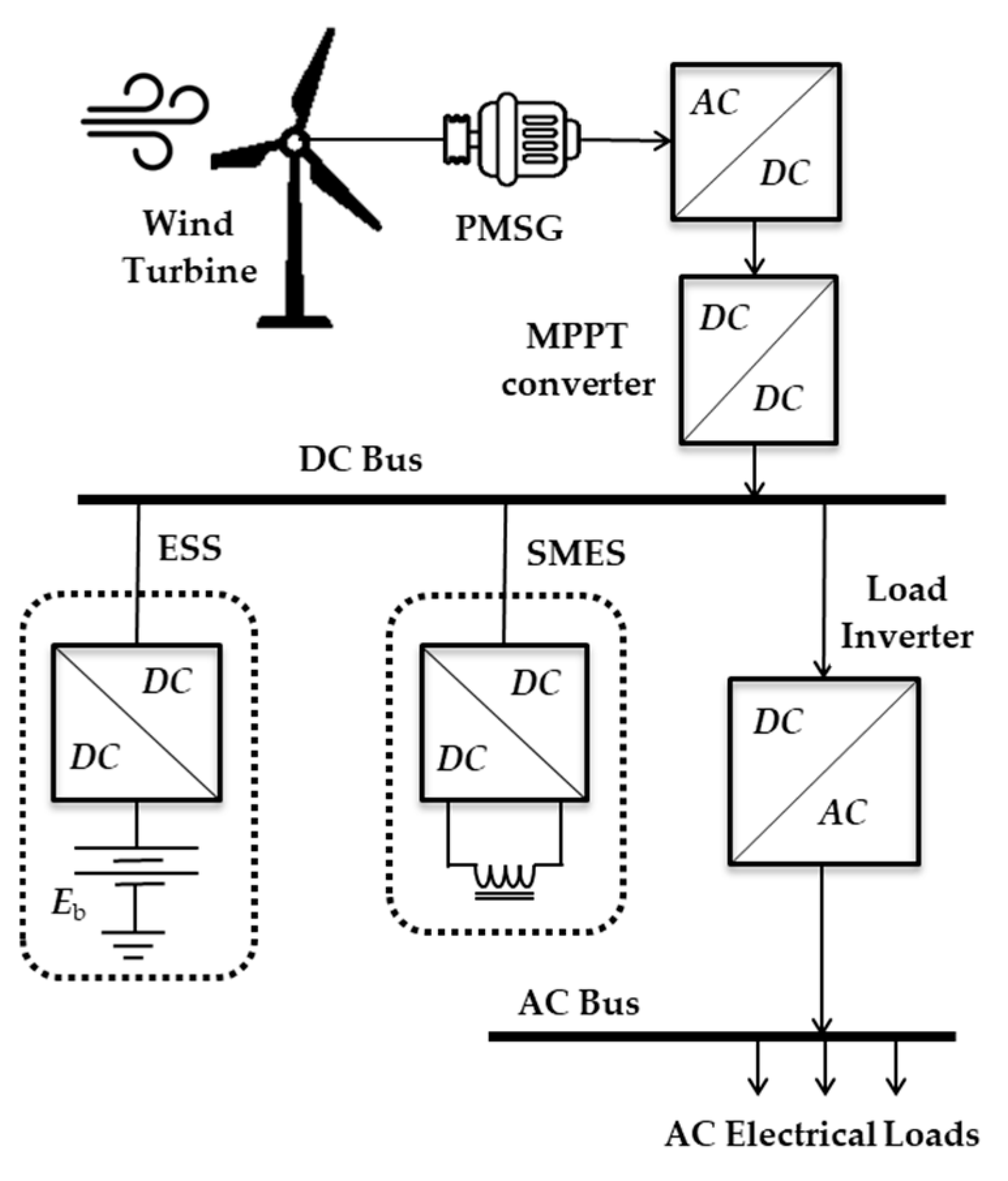
The recommended microgrid is a wind//battery/SMES that can sustain variable load, as presented in Figure 1. A wind turbine powers a 3-ϕ PMSG whose output is transformed to DC by the AC/DC rectifier. The end product of that converter represents the DC link of the microgrid. A 3-ϕ inverter is also delivered by the DC bus, and it is regulated to provide the microgrid loads with regulated AC power. The PMSG’s output often fluctuates along with variations in wind speed. As a result, a storage battery powers the load when the wind-producing unit’s output drops. Therefore, it serves as a slave to provide any extra power necessary for the load and to balance the decrease in wind power production. SMES is similarly essential for controlling wind generation and improving the transients of the microgrids. The wind’s varying speed frequently leaves the system’s load voltage uncontrolled. The load inverter uses a voltage controller to regulate the microgrid’s output voltage and frequency. In addition, the battery converter is a two-quadrant DC chopper. The job of that chopper is to control the battery’s state of charge. It also aids in the adjustment of the DC bus voltage. The battery converter is managed by the FPID controller.
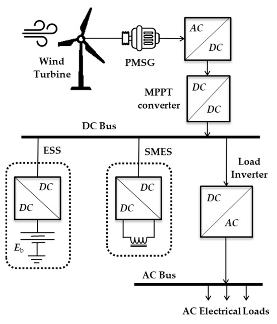
Figure 1.
The arrangement of the suggested microgrid.
3. Proposed Microgrid Components: An Overview
The specific model of each recommended microgrid component is clarified in the next subsections.
3.1. The Wind-Turbine Model
The power coefficient (Cp), function of the blade pitch angle (β) and tip speed ratio (λ), is used to describe the dynamic properties of wind turbines. To use wind energy best, (λ) should be set to its ideal value. As a result, the equivalent (Cp) will prevail. As shown in [24], the wind turbine power coefficient ratio of the tip speed, and power of the turbine (Pm) are:
where the density of the air is (ρ) and the swept area is (A).
3.2. The Generator Model
Reference [2] provides the PMSG’s d-q model:
where (rs) denotes the stator resistance, (isd, isq) the stator current’s d-q components, and (Ld, Lq) the stator current’s d-q inductances. The number of pole pairs is (p) and the permanent flux connection is (λm).
3.3. The AC/DC/DC Converter Model
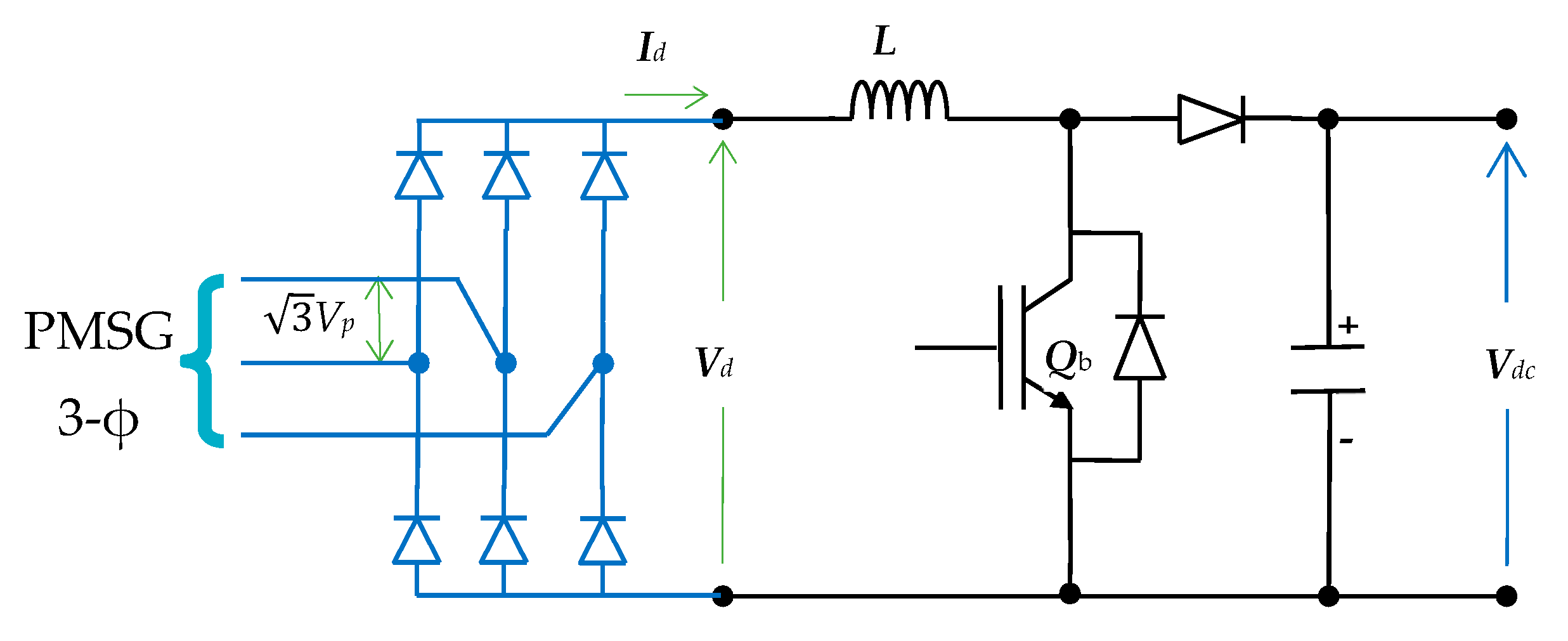
Actually, this converter has two cascaded converters: a rectifier and a boost converter as shown in Figure 2. It is commonly proven that the PMSG speed and wind speed are related. But the speed of the wind changes all the time. The PMSG’s voltage and frequency are not regulated since they mostly rely on its speed. To remedy this, the generator AC output is rectified and linked to the DC bus. Therefore, a power rectifier is utilized to source the loads with regulated AC power. This leads to the employment of an unregulated rectifier bridge. If the generator impedance is neglected, Reference [3] states that the rectifier’s usual relationships are as follows:
where the rectifier’s average output voltage and current are (Vd, Id), and (Vp, Ip) are the phase input voltage and current.
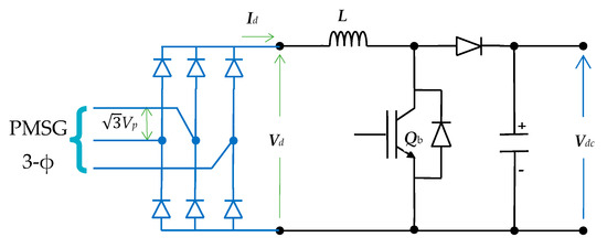
Figure 2.
The schematic of the AC/DC/DC Converter.
The boost converter output is the system DC bus, its input is the uncontrolled rectifier output. It is accountable for regulating the PMSG’s output to guarantee the MPPT conditions. Reference [2] provides the model of that converter.
where (Vdc, Idc) are the average output voltage and current of the buck converter, and (d1) is the duty ratio.
3.4. The Super Magnetic Energy Storage Model
For SMES, a huge superconducting coil that can store electrical energy as magnetic energy can be employed. It can be utilized for the SMES, because, at temperatures close to absolute zero, it has essentially negligible electrical impedance. The superconducting circuit is kept at a cryogenic temperature using containers filled with liquid helium or nitrogen. Energy is lost during the cooling process that maintains the coil’s temperature at its cryogenic value, but because superconductors have no barriers to electron flow, the losses vanish. SMES coils have a limitless capacity for storage cycles and can swiftly and effectively discharge large amounts of power. Low-temperature devices are currently available; however, high-temperature superconductor devices are still being developed thanks to their high price [35].
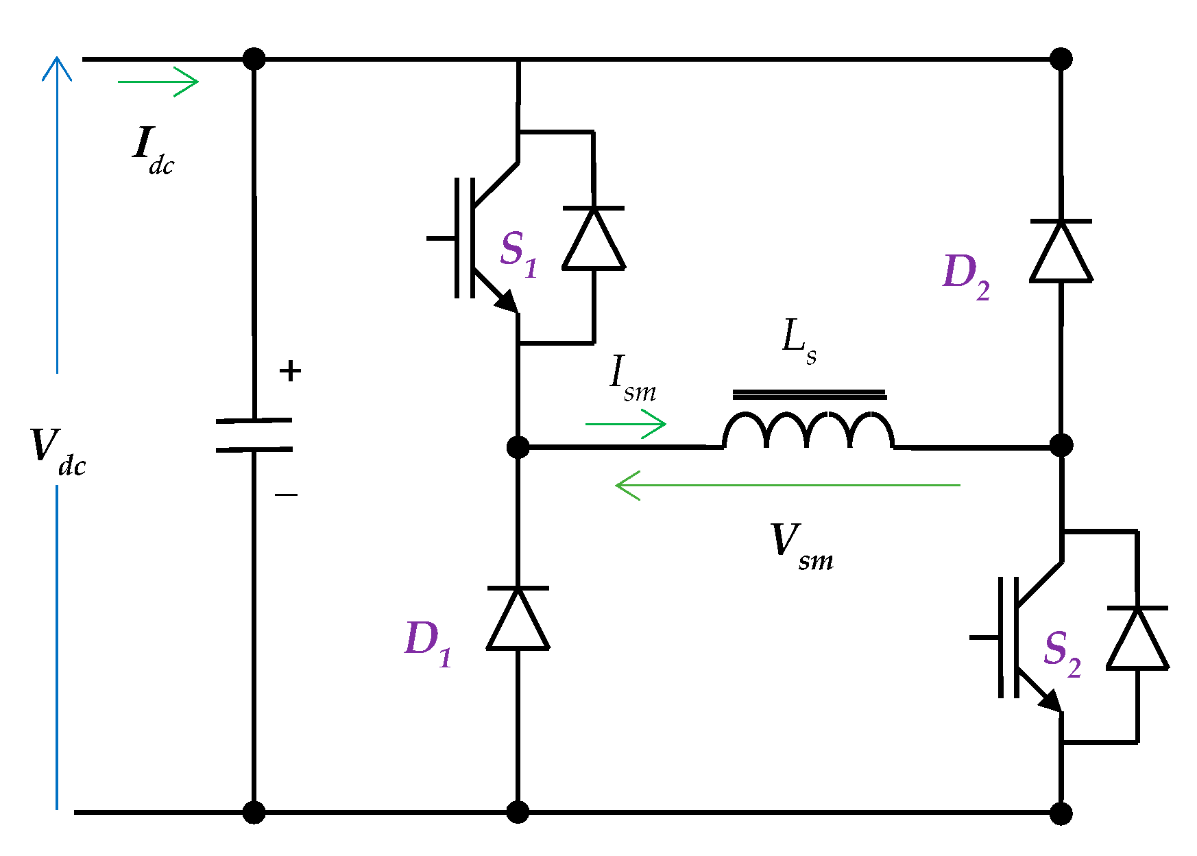
The SMES can be electrically modeled as a DC/DC bidirectional converter coupled to the SMES coil, as illustrated in Figure 3 [36]. The two-quadrant converter of the SMES operates on the simultaneous activation of its switches. The coil will be charged, and the diodes will be reverse-biased when switching on. The coil releases its energy, and the diodes turn forward-biased when switching off. The converter’s duty cycle may be changed to regulate the coil voltage. One way to represent the converter average model is [37]:
where (Ism, Vsm) is the average current and voltage of the SMES coil, (Idc, Vdc) is the average current and voltage of the DC link, and (k) is the duty cycle of the switches.
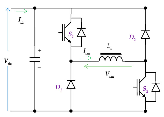
Figure 3.
The schematic of the SMES Converter.
3.5. The Battery Energy Storage Model
This converter’s job is to control how the ESS is charged and discharged. It is capable of supplying electricity in both directions. Figure 4 illustrates how this converter’s circuit was built. This converter’s input terminals are tied to the system DC bus. However, the storage battery is linked to its output terminals. The step-down mode and step-up mode are two categories in which this converter can operate. The converter functions in step-down mode when S2 is off, and S1 is modulated. In this mode, the storage battery is being charged. When S2 is modulated, and S1 is off, it behaves in step-up mode. Hence, the state of the storage battery is discharging at period.
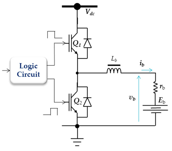
Figure 4.
The ESS chopper converter schematic.
The following describes the circuit model:
- − Charging state:
- − Discharge state:
3.6. The Output Converter Model
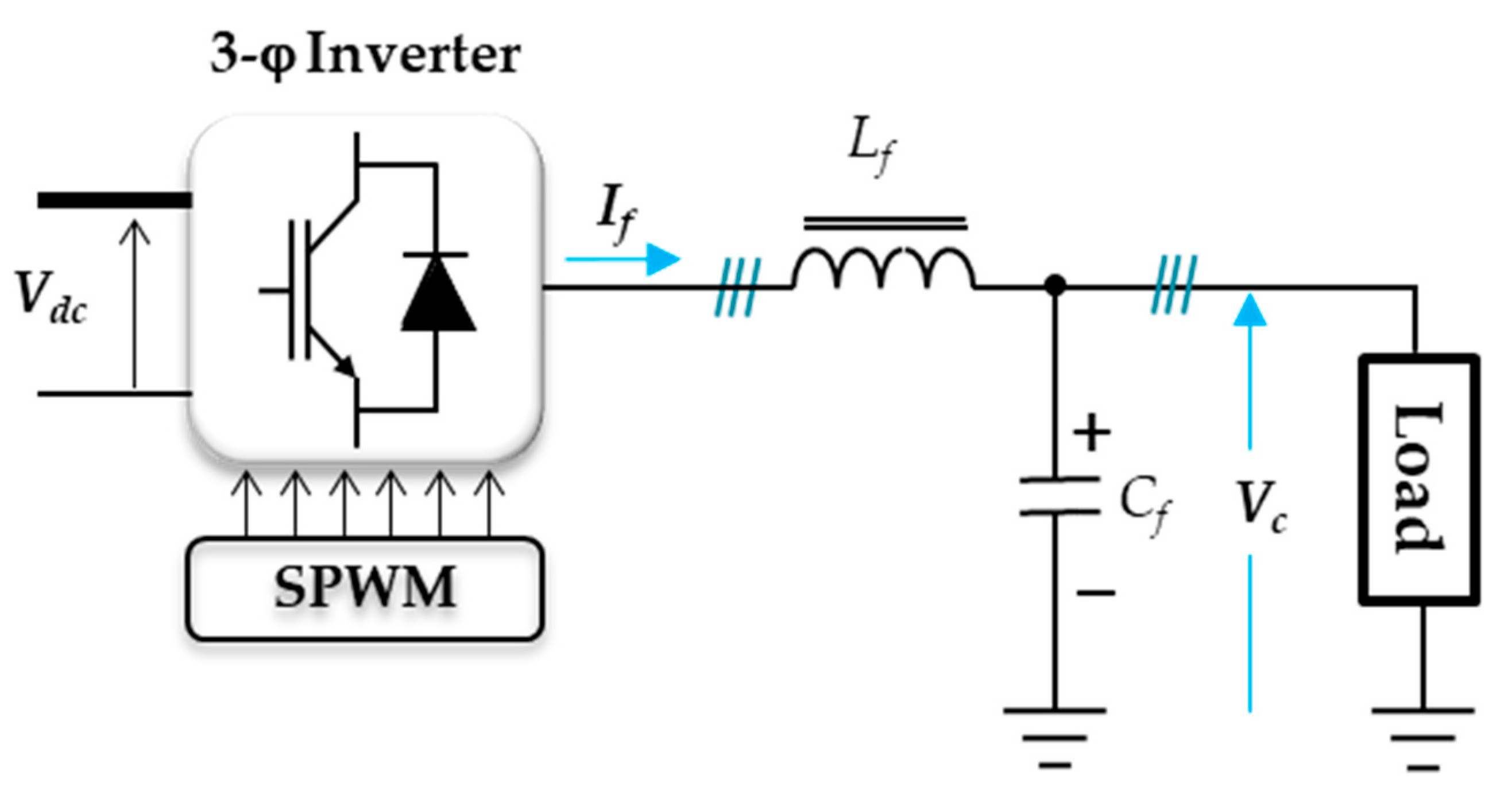
The circuit diagram of that converter, the 3-ϕ inverter, is shown in Figure 5. As a result, the inverter’s whole current and voltage are represented by [24]:
where (Io) is the output current, (Lf, Cf) are the filter inductance and capacitance, (Q) is the switching state, (Vc) is the capacitor voltage, and (If) is the filter current. All currents and voltages are space vectors.

Figure 5.
The output inverter.
4. Fuzzy PID Control
The physical properties of the controlled object—rather than its exact mathematical model—are the foundation of fuzzy control. Consequently, it works well for complicated nonlinear, time-varying systems and is ideal for physical systems that have no accurate models and unconditioned procedures with inadequate evidence. The inability of the fuzzy control to completely eliminate static error is one of its drawbacks. We can fully utilize the benefits of PID and fuzzy control to successfully enhance the performance of both dynamic and static systems by combining the two and employing fuzzy rules to adopt the PID gains in real time [38,39]. In the meantime, the resilience and performance of the system’s trouble elimination can also be enhanced. While fuzzy PID controllers are, no doubt, very useful in nonlinear systems, certain drawbacks, such as complexities in tuning and computational demands, noise sensitivity, and rule-base design sensitivity, cannot be gainsaid. Moreover, the occurrence of real-life issues with respect to parameter drift and interference could affect performance substantially. Hybrid methods, online tuning, and robustness analysis make them more adaptive and reliable [40].
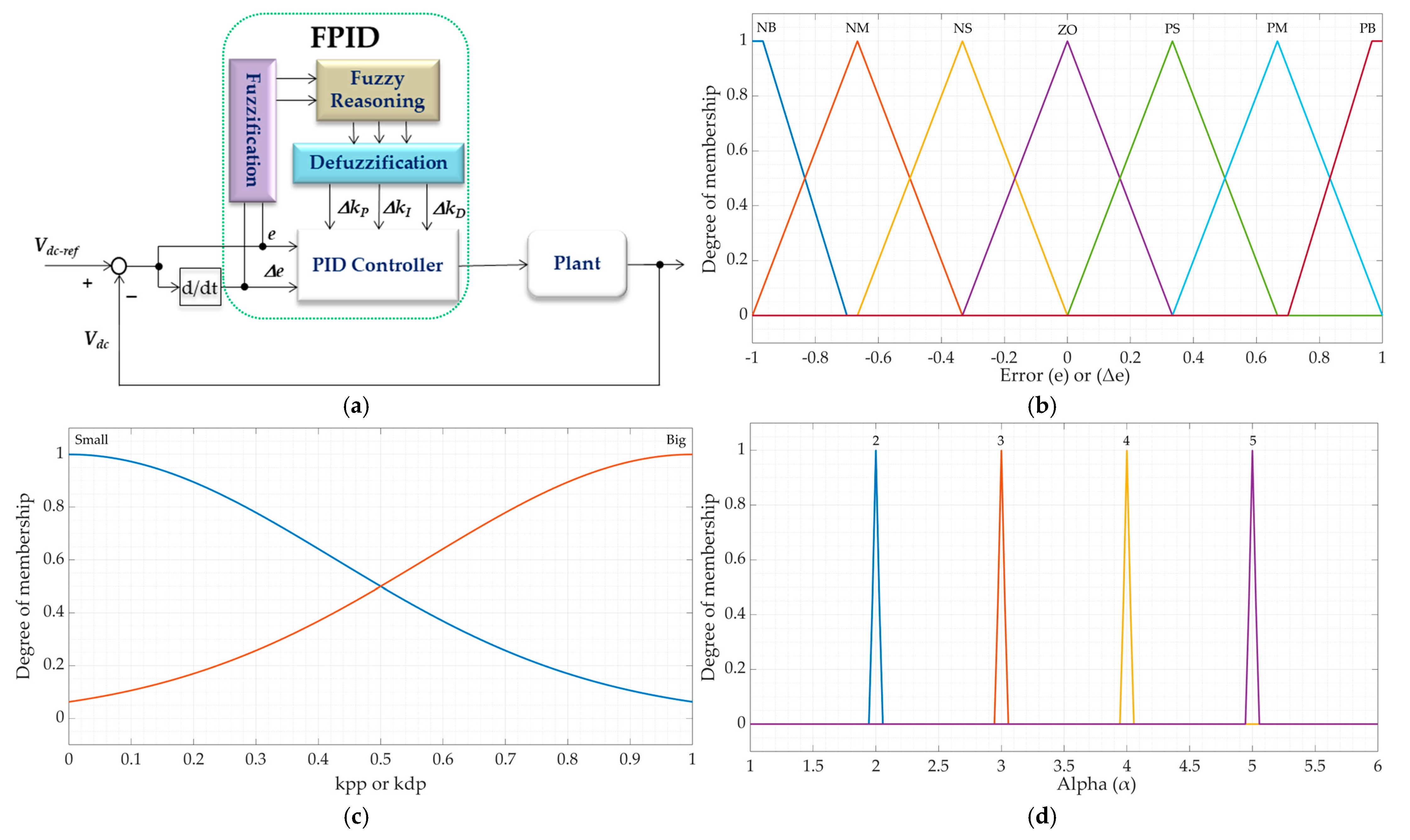
Figure 6a describes the FPID controller block diagram. The fuzzy logic idea and the traditional PID controller are combined to create the suggested self-tuning FPID controller. Based on the error (e) and its time rate (Δe), fuzzy logic concepts are utilized to tune the parameters of the traditional PID controller generating FPID controller. Here, the strategy is to derive PID controller settings by utilizing fuzzy reasoning. The discrete PID controller equation is:
where u is the output of the controller signal. It serves as the inner current loop’s reference current.; “n” is the sample order.
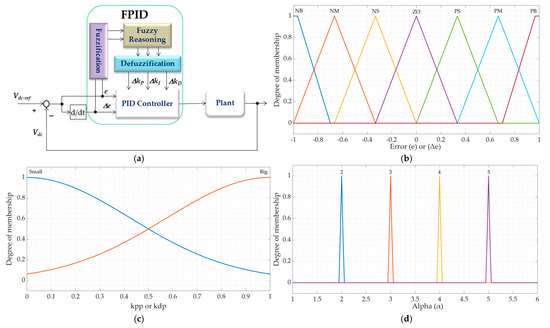
Figure 6.
(a) Fuzzy logic controller main stages, (b) the input membership function, and (c,d) the output membership function.
The gains of the PID regulator (kP, kI, kD) are established according to the error and the error rate (e, Δe), where
where T is the sampling period.
Usually, the error components (e and Δe) are limited to the range [1, 0] for simplicity:
where (en and Δen) are the normalized error values.
Determining how the three parameters will be altered in response to the system feedback signal is the design challenge. Hence, finding and using intuitionistic principles from human knowledge and experience to determine their correlations is the fundamental idea behind fuzzy control in this context. The principles of PID tuning adhere to the subsequent rules in long-term practice [39]:
- In order to ensure excellent tracking performance, kP should take a greater value when |e| is larger. kD should have a lower value to avoid integral saturation. Simultaneously, the integral part must be constrained, kI should likewise be extremely tiny, and typically let kI = 0 to prevent more overshoot during the system response.
- To guarantee system reaction speed and a lesser overshoot, KP must be reduced when |e| has a moderate amount, and kI and kD have to be suitable. (The system responsiveness is more affected by the value of kD, thus kI should be set appropriately).
- To achieve excellent steady-state response, kP and kI should take bigger values when |e| is less. kD should be suitable to prevent chattering. kD may be smaller when |Δe| is greater. kD may accept a somewhat larger amount when it is smaller. Typically, kD takes a modest value.
Figure 6a illustrates the three main parts of the fuzzy logic controller. These three components are the rule base, the fuzzification stage, and the defuzzification stage. The fuzzifier transforms the input’s crisp values into fuzzy values before sending them to the rule base. For simplicity, the linguistic values have been assigned seven levels. Three regions positive (P), negative (N), and zero (Z) as well as sub-regions for malls make up the rule basis. Negative large (NB), small (NS), medium (NM), positive big (PB), medium (PM), and positive small (PS) are the designations for these variables [12]. The linguistic values are given the membership function with the triangle waveform. Figure 6b displays the membership functions for (e, Δe).
If we return to the PID parameters, it can be determined using:
where (AP, Ad) are the predetermined constants for the PID parameters; (ΔP, Δd) are the change in the pre-determined PID parameters values; (α) is the integral parameter adjusting value. The linguistic values of (ΔP, Δd, α) are determined by Figure 6c,d.
A series of if-then rules based on specified expert knowledge are used to represent the rule basis. Then, the defuzzifier transforms rule-base output values into crisp values [41,42].
Table 2 presents the rule basis for the fuzzy logic controller’s two inputs and three outputs. These are the three gain values of the PID controller as well as the error, e, and change in error, Δe.
Table 2.
The rule basis for the fuzzy logic controller [12].
The fuzzy control rules used per the real operation experience control system are shown in Table 2. Figure 7 indicates the control surface of the fuzzy logic controller.
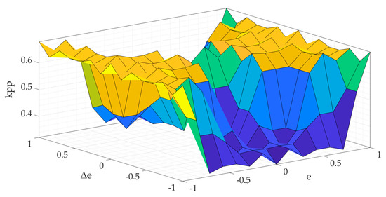
Figure 7.
The control surface of the fuzzy controller.
5. The Control System of the Microgrid
The suggested microgrid has three control loops: the output-converter controller, the controller of the ESS chopper, and the SMES converter controller. These are shown in Figure 8. The SMES converter controller is employed to control the charging and discharging of the SMES coil as well as the transient voltages in the DC connection. The charge and discharge of the ESS are also controlled by the ESS converter controller. Furthermore, it aids in regulating the DC bus voltage. On the other side, the primary inverter controller is controlled by the third controller. It regulates the load’s voltage and frequency. The next sections go through these controllers’ specifics.
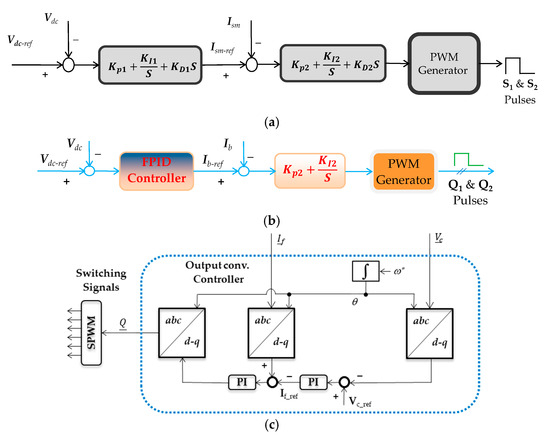
Figure 8.
(a) The ESS’s chopper controller, (b) the SMES’s converter controller, and (c) the output-converter controller.
5.1. The SMES’s Converter Controller
The task of this controller is to regulate the state of charge of the SMES’s coil and support the stabilization of the DC link. As a backup, it also regulates the DC link voltage in combination with the ESS converter. As shown in Figure 8a, the current and voltage of the SMES are controlled by a simple PID controller employing two stacked loops. The first loop is responsible for the DC link’s voltage regulation. The controller’s output is the reference current of the SMES coil. When compared to the actual SMES’s current, the error signal will be produced and fed to the second controller. The output of the second controller is a reference signal of the PWM generator unit. That unit is responsible for generating the pulses with the suitable duty cycle for the converter switches (S1, S2). The SMES’s controller ends up charging the coil of the SMES when the current approaches its upper limit.
5.2. The ESS Chopper Controller
The ESS chopper controller regulates the DC link voltage and ESS charging and discharging. For the system to function and be stable, the DC link voltage must be stabilized. As indicated in Figure 8b, the FPID controller is utilized for the stabilization of the DC bus voltage. It is formed of two layered controllers which make up the control system. The first layer regulates the current, while the outer layer regulates the voltage of the DC link. The voltage control of the DC link is the responsibility of the first loop. The storage battery’s reference current is the controller’s output. The error signal will be generated and sent to the second controller in comparison to the current of the real storage battery. The PWM generating unit’s reference signal is the second controller’s output. That unit oversees producing pulses for the converter switches (Q1, Q2) with the appropriate duty cycle. This procedure is termed the constant current-voltage approach. The fuzzy control tuning approach is used to adapt the PID parameters.
5.3. The Output Converter Controller
The output converter is essentially a current-controlled inverter. Therefore, the controller consists of two stacked control loops presented in Figure 8c, in which the outer loop or the output voltage loop compares the measured output voltage with the reference value. The PID controller receives the error and uses it to create the current’s set point. A comparison is made between the measured load currents and the set currents. A pulse width modulator, that creates the inverter pulses, is then fed with the error produced to provide the converter switching signals.
6. Discussion of the Simulation Results
Digital computer simulations were used to verify the performance of the investigated microgrid using the suggested controller, as illustrated in Figure 9, Figure 10, Figure 11 and Figure 12. This system was modeled and tested using the MATLAB/SIMULINK software (v.23.2 released 2023b) suite to accommodate several operation tactics for variations in wind velocity and load characteristics. Table 3 provides microgrid parameters. Testing of the microgrid’s response was performed with varied wind speeds and AC load, both with and without SMES.
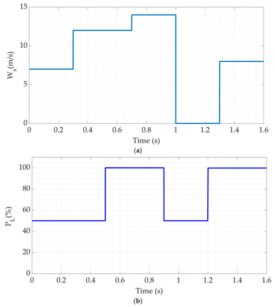
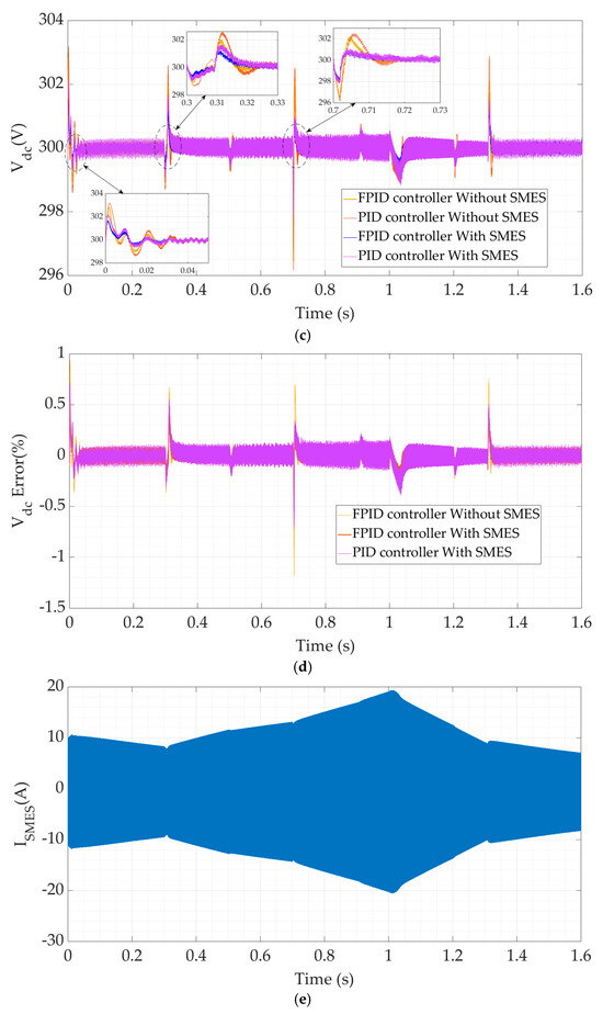
Figure 9.
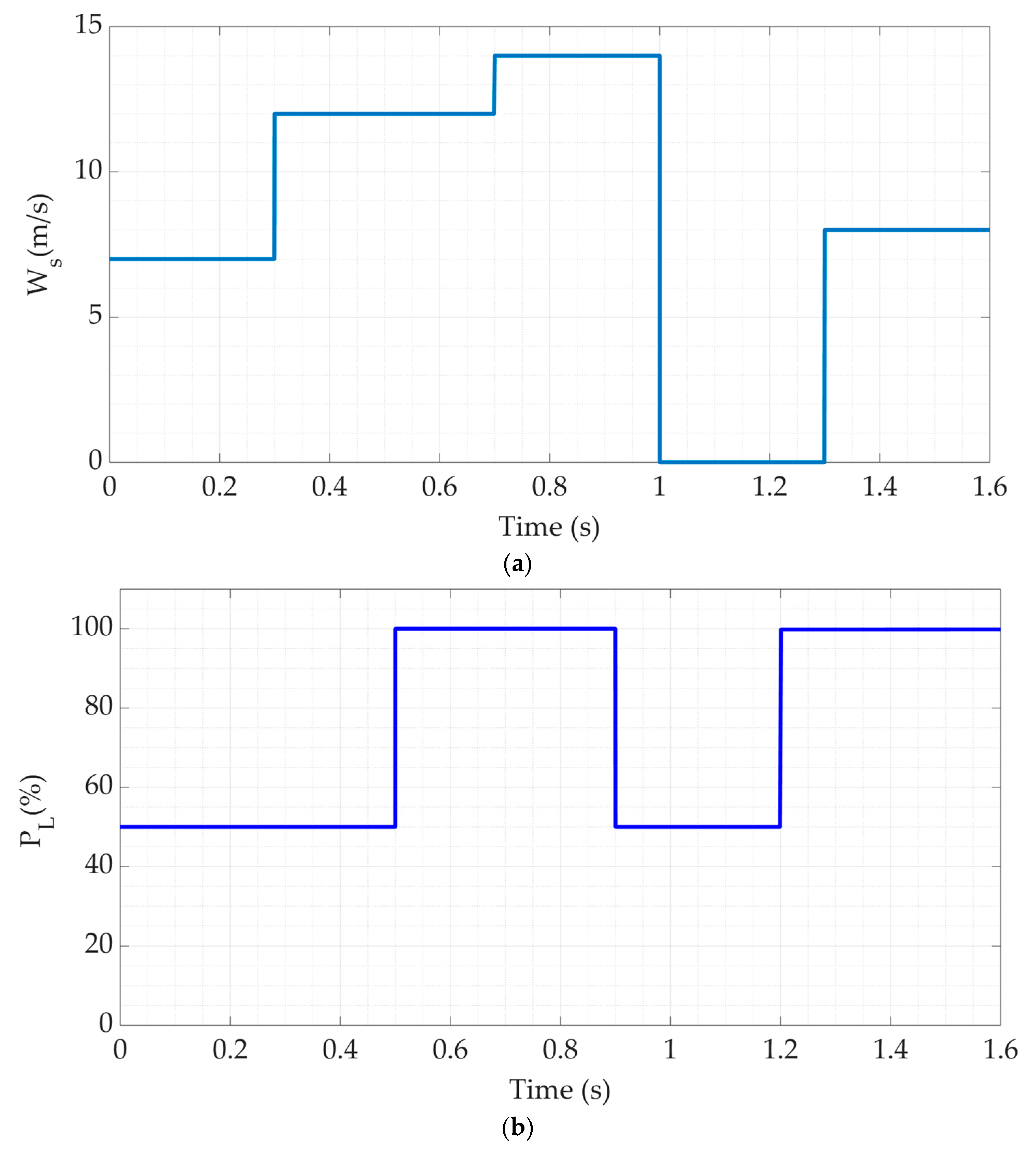
(a) The wind velocity, (b) the employed load power, (c) the DC link voltage, and (d) the DC link voltage errors and (e) the injected SMES current.
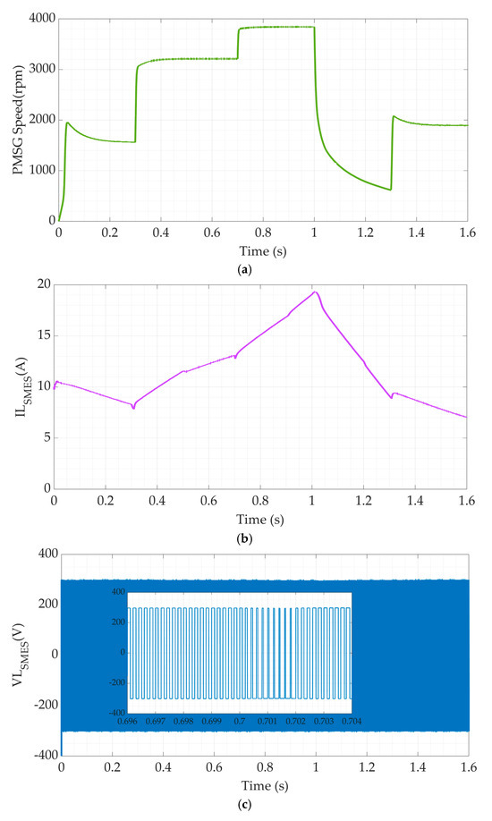
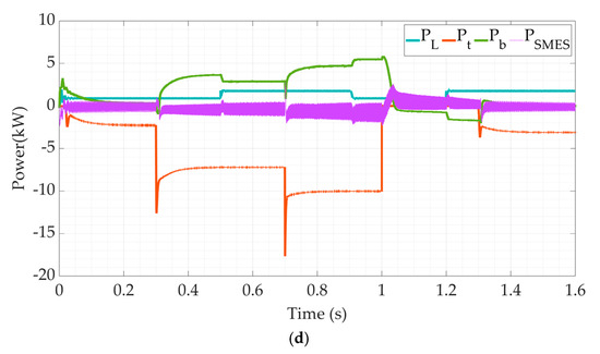
Figure 10.
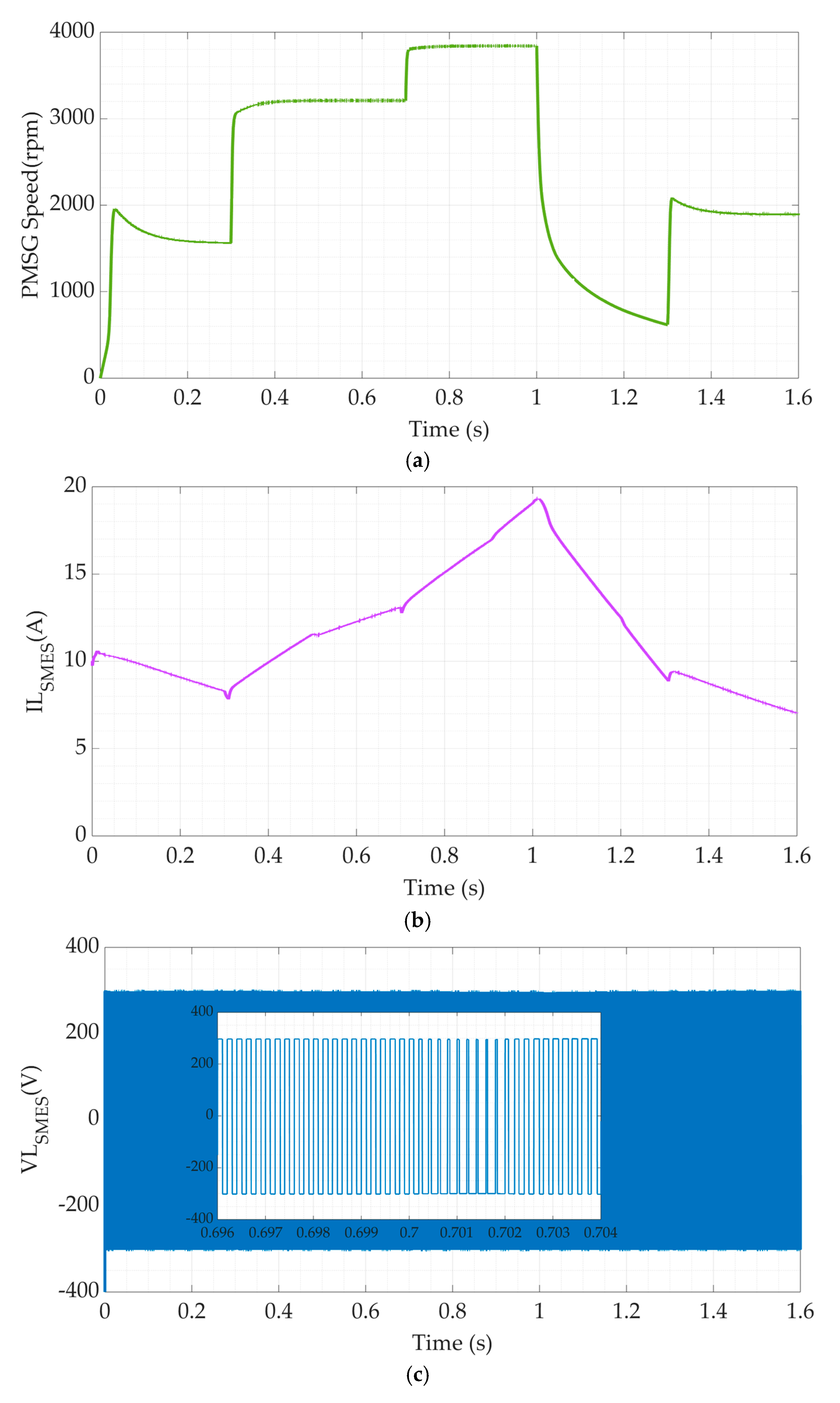
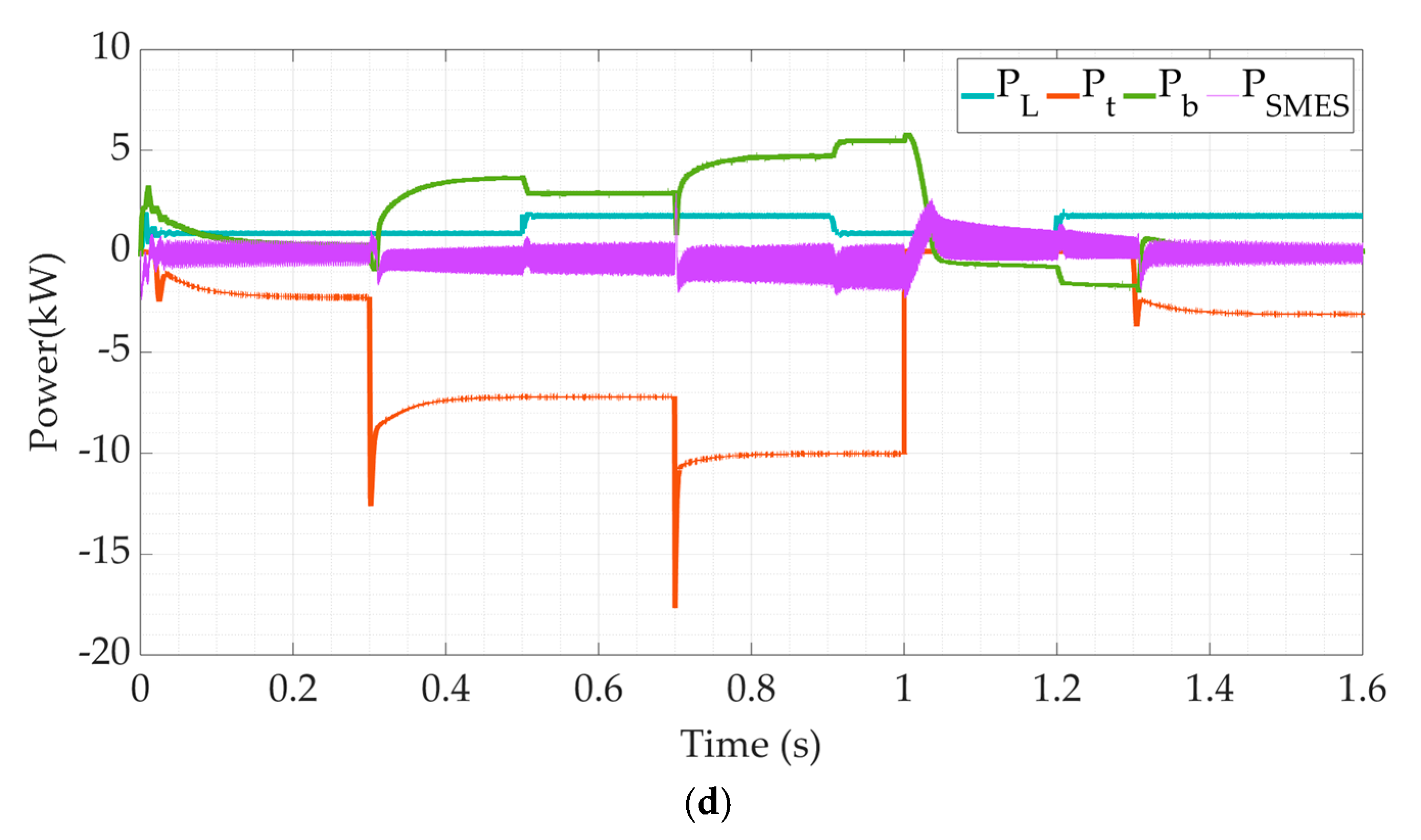
The microgrid simulation’s responses with SMES using the proposed FPID (a) PMSG speed, (b) SMES coil current, (c) SMES coil voltage, and (d) system powers.
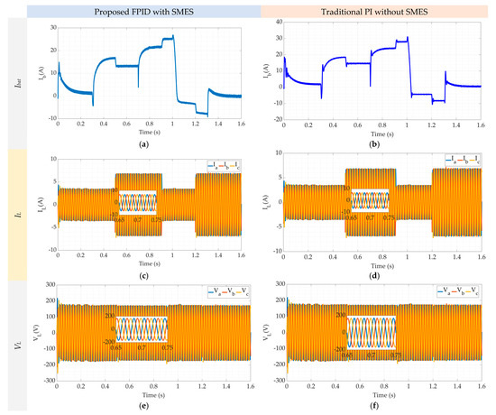
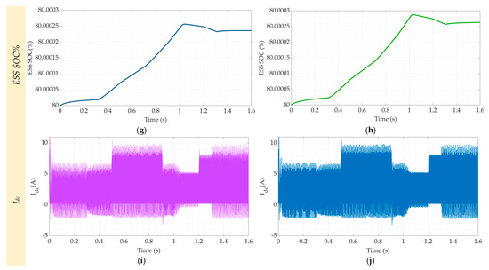
Figure 11.
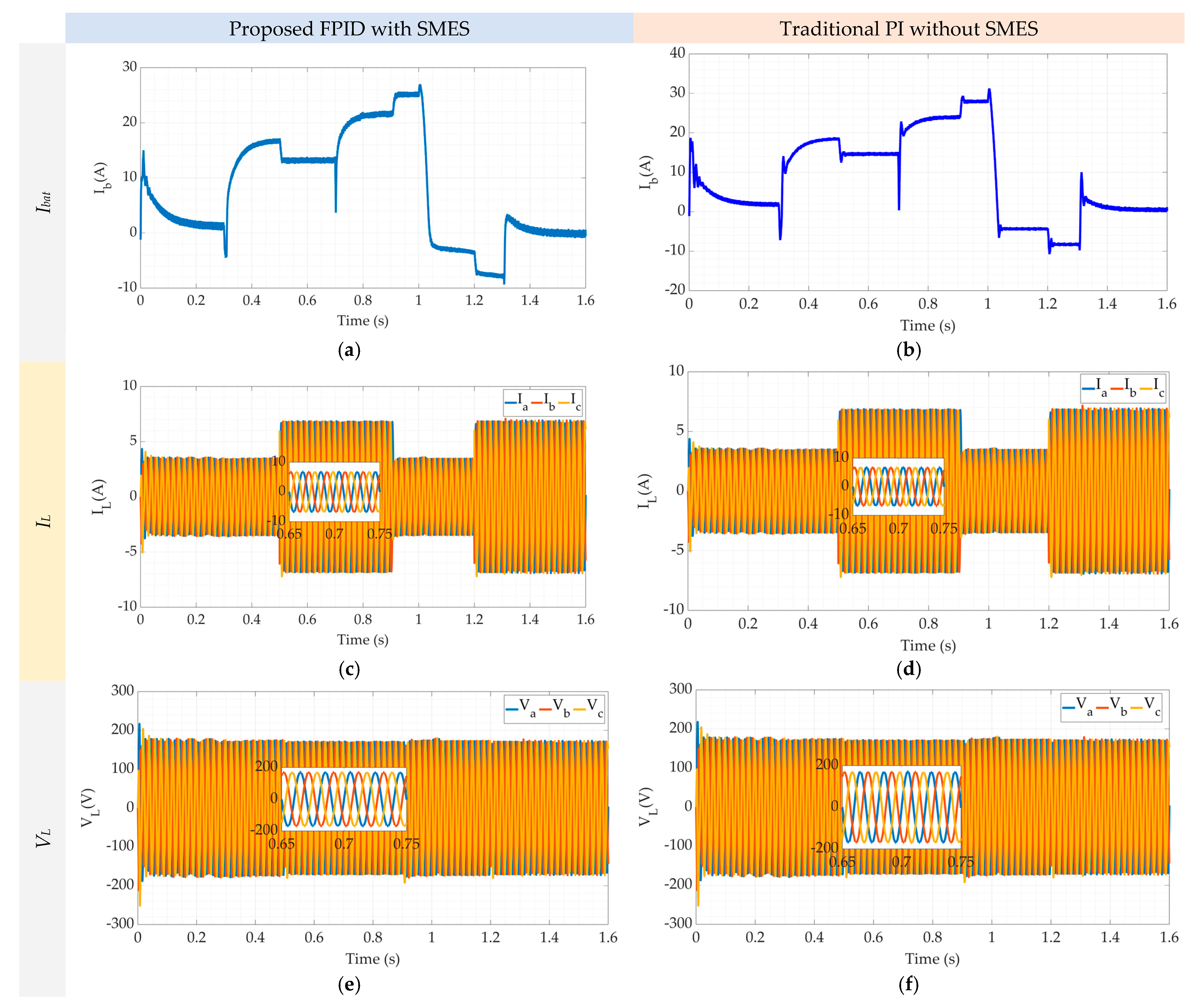
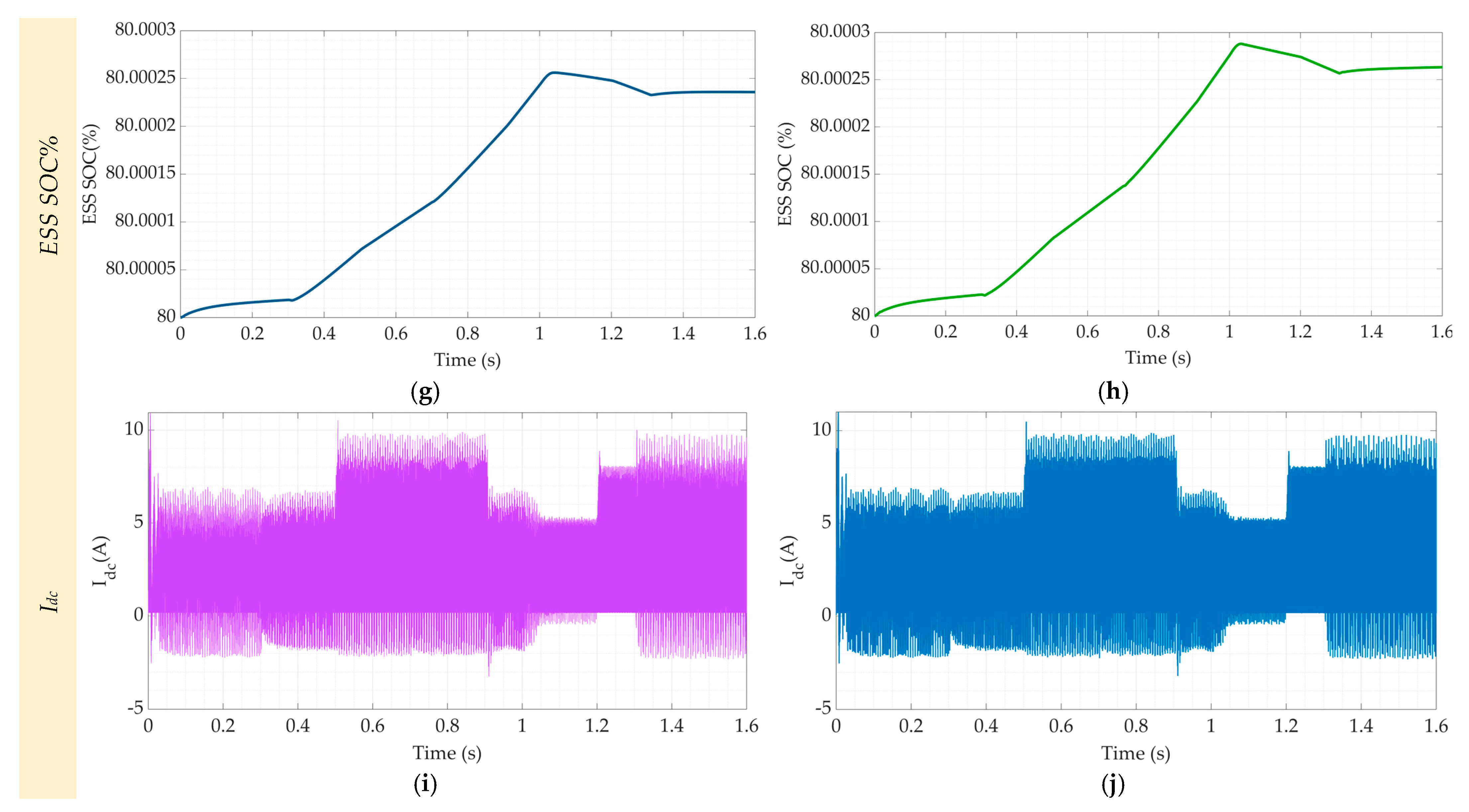
The microgrid simulation’s responses with/without SMES using both controllers: the proposed FPID (a,c,e,g,i) and the conventional PID (b,d,f,h,j).
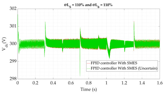
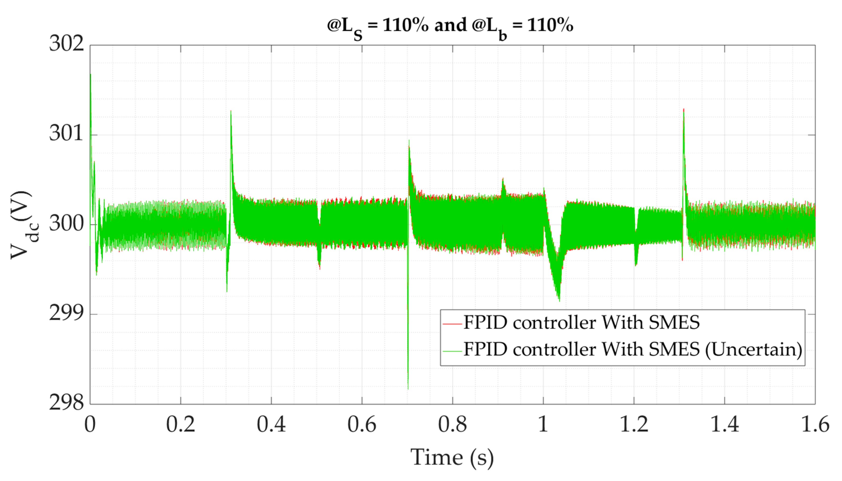
Figure 12.
The DC link voltage under variations in the system’s parameters.
Table 3.
The suggested AM drive settings.
The findings for a few of the suggested microgrid parameters are shown in Figure 9. Step changes in wind speed (Ws) were applied to the microgrid, as Figure 9a illustrates. Throughout the duration [0–0.3s], the wind velocity has been maintained at 7 m/s; it stepped to 12 m/s at time 0.3 s, rose to 14 m/s at the time of 0.7 s, and fell to 0 m/s at time 1s. Finally, a step change in the wind speed of 8m/s is applied at time 1.3 s. Figure 9b presents the load power variations that are indicated by the step changes in the load demand at the timings (0, 0.5 s, 0.9 s, and 1.2 s). These variations in the load power represent another type of disturbance for the control system. Figure 9c compares the DC bus voltage responses using the suggested FPID and traditional PID controllers. The comparison was performed in two situations: with and without the presence of the SMES. In fact, that figure compares four cases for the suggested microgrid:
- The FPID controller with SMES.
- The PID controller with SMES.
- The FPID controller without SMES.
- The PID controller without SMES.
The finest response is obviously delivered by the proposed FPID controller with the SMES in operation. It can be noticed from the subfigures that the main improvement with the proposed controller is the peak-to-peak overshoot. However, the steady-state error for all cases is zero. On the other hand, the settling times for all cases and at the different disturbances are almost the same. This can be understood if complexities such as the visualized huge damping of the filters and SMES’ components are visualized. The traditional PID regulator without SMES had the worst performance. Moreover, the overshoot and the overall transient performance of the DC bus voltage, with SMES and the suggested FPID regulator, is better than that without SMES. Outlines of the percentage errors in the DC link voltage for the previous four cases are shown in Figure 9d. Nevertheless, the error shape with the proposed FPID controller is the lowest with the presence of the SMES unit. Nevertheless, the traditional PID regulator, without utilizing the SMES, has the worst response of all the cases. Figure 9e illustrates the injected SMES current to the DC bus. The current is alternating in nature. However, its peak varies according to the energy requirement of the DC bus. It has been observed that the load and wind speed transients are associated with the rapid variations in SMES energy and current. SMES enhances the DC bus voltage’s transient reactivity by allowing the coil to charge and discharge in accordance with controller orders. Additionally, when the wind increases, the SMES current increases quickly, and vice versa. This problem aids in reducing undesired transients and system oscillations. Therefore, the transient performance is enhanced when SMES are present in the system.
The remaining findings for the suggested microgrid’s parameters are shown in Figure 10. The PMSG speed, predicted in Figure 10a, is typically proportionate to the wind speed of Figure 9a. Furthermore, as Figure 10b illustrates, the SMES coil current is a pure DC but varies in its value. The coil is charging during the high wind speed periods, while it discharges during the low wind speed periods. The changes in the SMES coil current value may deliver or absorb energy from the DC bus to improve the transient response of the microgrid. Figure 10c shows the SMES coil voltage. According to the traditional operation of the SMES converter, the coil voltage oscillates ± Vdc in a pulse width modulation (PWM) manner. The controller adapts the PWM such that the required energy by the DC bus is delivered to achieve a better transient response. The major powers in the proposed power system using the FPID controller with SMES are presented in Figure 10d. It is viewed that the integration of SMES power with battery power is thought to enhance response and control the microgrid’s energy status. In all circumstances, the overall powers are the same. The high-frequency variations in the SMES power are caused by the SMES’ converter switching.
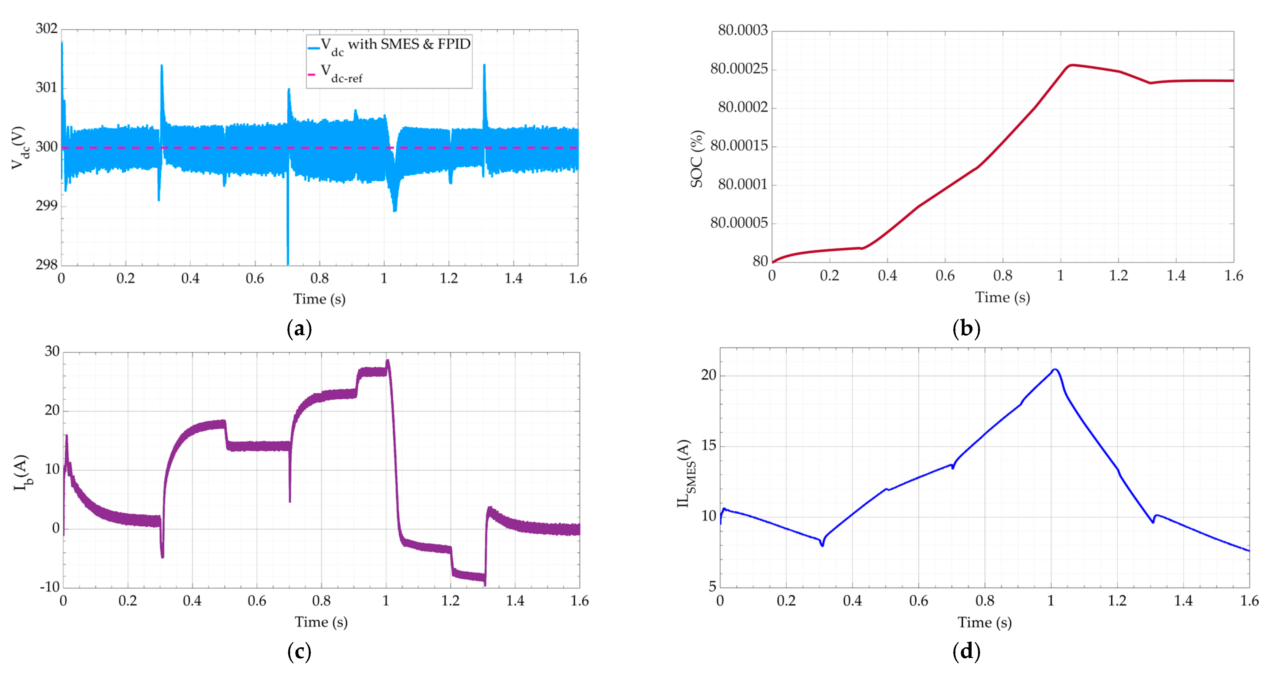
Figure 11 predicts the comparison of the microgrid response using two cases: (1) the FPID controller with SMES and (2) the traditional PID without SMES. The responses of the battery or ESS’s currents are presented in Figure 11a,b. The response of case (1) FPID with SMES appears to be more damped than the battery’s current response to case (2) without SMES. Additionally, depending on the amount of wind energy, the battery current charges and drains the battery in both cases. The load voltage and current responses using both cases are shown in Figure 11c–f, respectively. It is demonstrated that while the load current fluctuated based on the demand load, the AC load voltage kept at its level in both frequency and amplitude. The controller applies a perfect energy management procedure. Hence, the charging state of the ESS is based on the wind velocity level. If the wind speed is high enough, the ESS charges; otherwise, it discharges to supply the required demand. The battery’s state of charge (SOC) in both scenarios is displayed in Figure 11g,h. In both circumstances, the SOC’s profile is identical except for a slightly higher SOC during periods of high wind speeds. It is noted that the SOC in case (2) without SMES is greater than that in case (1) FPID with SMES. The reason behind that phenomenon is the energy utilized by the SMES reduces the available charging energy of the ESS’s battery. Figure 11i,j illustrate, respectively, how the DC link current responds under the suggested disturbances using both cases. It is noted that the DC link voltage transient responsiveness has been enhanced in case (1), FPID with SMES, and is more consistent than in case (2), PID without SMES.
To evaluate the robust stability of the recommended FPID regulator vs. the fluctuations of the microgrid parameters, a few of the system’s variables are altered. There is an increase of 10% in the SMES’s inductance (Ls) and the battery converter inductance (Lb), simultaneously. The microgrid’s response under parameter ambiguity is illustrated in Figure 12. It is discovered that the proposed regulator can precisely maintain the system stable under any disturbances, notwithstanding the modeling errors.
Using the proposed FPID and the conventional PID controller, Table 4 evaluates the peak overshoot for the DC bus voltage for each period of the findings. Both controllers are applied to the microgrid while the SMES is in operation. The DC bus voltage has a much lower peak overshoot with the proposed FPID compared with the conventional PID controller for a variety of load power (Pl) and wind velocity (ωs) disturbances. Using both controllers, the steady-state error is nearly eliminated for all troubles, and the average improvement in overshoot is roughly 24.4%. Both controllers have almost the same settling time.
Table 4.
Performance comparison of the proposed microgrid, with the SMES, using both the traditional PID and the suggested optimized FPID controllers.
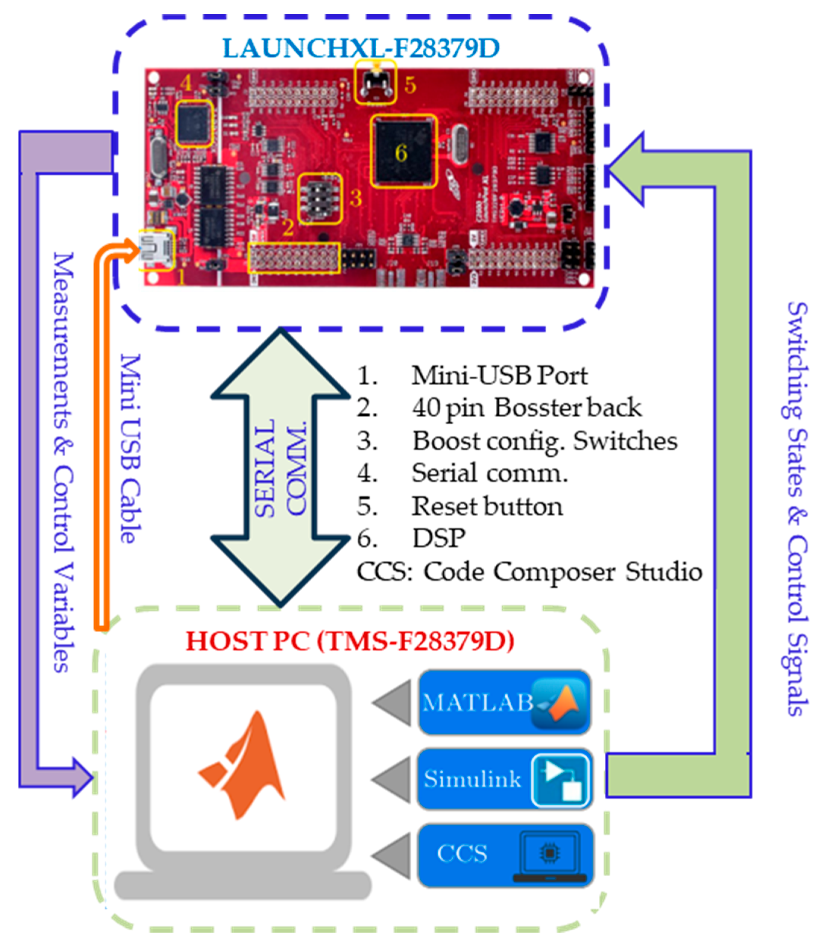
The TI C2000 Launchpad XL, TMS320F28379D kit (Texas Instruments, Kuala Lumpur, Malaysia) was used to create a HIL emulator in order to assess the suggested system and verify the simulation findings, as shown in Figure 13. The system is divided in this configuration by the HIL emulator, which usually hosts the power components on a personal computer as a model in MATLAB. MATLAB is used to simulate the power units of the suggested system, which include the wind turbines, power converters, SMES, battery, and filters. During this time, the microcontroller kit runs the control procedures, namely the FPID. A virtual serial communication port is used to establish connection between the PC and the microcontroller. This enables MATLAB to transmit the measured signals from the power setup of the microgrid, including the DC link voltage, to the microcontroller.
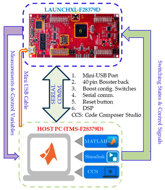
Figure 13.
Diagrammatic representation of the HIL implementation using the TI C2000 Launchpad XL, TMS320F28379D kit.
Figure 14 presents the response of the suggested microgrid (with the SMES) utilizing the proposed FPID controller using the HIL implementation. The findings are relatively near to those presented in Figure 9.
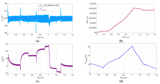
Figure 14.
The response of the suggested microgrid (with SMES) utilizing the proposed FPID controller using the HIL implementation (a–d).
7. Conclusions
In this article, a green isolated microgrid is illustrated. It has a wind energy generator, a superconducting magnetic energy storage system, and an ESS. The FPID controller can be adapted to improve the performance of the proposed microgrid. Under typical conditions, wind and ESS energies are suitable for fulfilling load requirements. On the other hand, the SMES steps in to cover the extra capacity required in emergency scenarios. The behaviors of the microgrid against step variations in load demand and wind velocity were observed using the newly developed FPID regulator. Matlab/Simulink implementations were run to assess the performance of the suggested system. The results indicate that, despite any interruptions, the introduced microgrid successfully delivers the load in a precise behavior. In addition, the recommended controller can stabilize the DC link voltage. Consequently, the load voltage tracks their set amounts despite changes in wind velocity and demand load. Evaluation and comparison of the ideally regulated microgrid’s performance with and without the SMES were conducted. The findings show that the SMES significantly enhanced the dynamic responsiveness and reduced all sorts of overshoots in the response. The proposed control system provides an average improvement in overshoot of about 24.4%. Moreover, it is discovered that the proposed FPID regulator can precisely keep the system stable under all disturbances in the load power and wind velocity, notwithstanding the modeling errors. The proposed FPID controller with SMES has a flawless load voltage response and lower overshoot than the case without the SMES with the PID controller. Ultimately, the microcontroller (TI C2000 Launchpad XL, TMS320F28379D) kit was used to create a Hardware-in-the-Loop (HIL) emulator in order to assess the suggested system and verify the simulation results. One of the limitations of this research is the relatively small power rating. This issue affects the system’s inertia and dynamics. Consequently, the wind velocity variations are assumed to be relatively fast. Another limitation of the FPID controller is the high computational load, which makes it less suitable for real-time applications that require a very fast response.
Author Contributions
Writing—review and editing, K.S.A.; formal analysis and conceptualization, S.A.Z. All authors have read and agreed to the published version of the manuscript.
Funding
This research received no external funding.
Data Availability Statement
The original contributions presented in the study are included in the article, further inquiries can be directed to the corresponding author.
Conflicts of Interest
The authors declare no conflicts of interest.
Nomenclature
| ESS | energy storage system |
| SMES | superconducting magnetic energy storage system |
| FPID | fuzzy-order proportional–integral-derivative |
| PID | proportional–integral–derivative |
| PMSG | permanent magnet synchronous generators |
| AC | alternating current |
| DC | direct current |
| PWM | pulse width modulation |
| rs | stator resistance |
| (isd, isq) | stator current’s d-q components |
| (Ld, Lq) | stator current’s d-q inductances |
| p | number of pole pairs |
| λm | permanent flux connection is |
| (Vp, Ip) | PMSG phase out put input voltage and current |
| (Vd, Id) | rectifier’s average output voltage and current |
| (Vdc, Idc) | average output voltage and current of the boost converter |
| d1 | the boost converter duty ratio |
| (Ism, Vsm) | is the average current and voltage of the SMES coil |
| (Idc, Vdc) | average current and voltage of the DC link |
| k | duty cycle of the boost converter switch |
| (rb, Eb) | internal resistance and the voltage of the ESS |
| (C, L) | capacitance and inductance of the filter of ESS converter |
| (vb, il) | capacitor voltage and inductor current |
| S1 | logic-state function |
| Io | output current |
| (Lf, Cf) | filter inductance and capacitance of the load inverter |
| Q | switching state function of the load inverter |
| Vc | capacitor voltage of the load inverter |
| If | filter current of the load inverter |
| (e, Δe) | error and its derivative |
| (kP, kI, and kD) | PID controller gains |
| T | sampling period |
| (en, Δen) | normalized error and its derivative |
| (AP, Ad) | predetermined constants for the PID parameters |
| (ΔP, Δd) | change in the pre-determined PID parameters values |
| α | integral parameter adjusting value |
| R | turbine blade radius |
| Pm | turbine’s output power |
| ρ | air density |
| vw | wind velocity |
| β | blade pitch angle |
| Cp | wind turbine’s performance coefficient |
| ωm | mechanical angular speed of the turbine |
| λ | tip-speed ratio |
| Ls | SMES’s inductance |
| Lb | battery converter inductance |
| μG | Microgrid |
| HIL | Hardware-In-the-Loop |
References
- Atawi, I.; Zaid, S. Model predictive control of h7 transformerless inverter powered by pv. Intell. Autom. Soft Comput. 2022, 31, 449–469. [Google Scholar] [CrossRef]
- Atawi, I.E.; Kassem, A.M.; Zaid, S.A. Modeling, Management, and Control of an Autonomous Wind/Fuel Cell Micro-Grid System. Processes 2019, 7, 85. [Google Scholar] [CrossRef]
- Albalawi, H.; Kassem, A.M.; Zaid, S.A.; Lakhouit, A.; Arshad, M.A. Energy management of an isolated wind/photovoltaic microgrid using cuckoo search algorithm. Intell. Autom. Soft Comput. 2022, 34, 2051–2066. [Google Scholar] [CrossRef]
- Guerrero, J.M.; Chandorkar, M.; Lee, T.; Loh, P.C. Advanced Control Architectures for Intelligent Microgrids—Part I: Decentralized and Hierarchical Control. IEEE Trans. Ind. Electron. 2013, 60, 1254–1262. [Google Scholar] [CrossRef]
- Rosso, R.; Wang, X.; Liserre, M.; Lu, X.; Engelken, S. Grid-Forming Converters: Control Approaches, Grid-Synchronization, and Future Trends—A Review. IEEE Open J. Ind. Appl. 2021, 2, 93–109. [Google Scholar] [CrossRef]
- Kirubadevi, S.; Sutha, S. PMSG based wind energy conversion system using intelligent mppt with hgrsc converter. Intell. Autom. Soft Comput. 2022, 34, 895–910. [Google Scholar] [CrossRef]
- Merabet, A.; Ahmed, K.T.; Ibrahim, H.; Beguenane, R.; Ghias, A.M.Y.M. Energy Management and Control System for Laboratory Scale Microgrid Based Wind-PV-Battery. IEEE Trans. Sustain. Energy 2017, 8, 145–154. [Google Scholar] [CrossRef]
- Ahmed, S.D.; Al-Ismail, F.S.M.; Shafiullah, M.; Al-Sulaiman, F.A.; El-Amin, I.M. Grid Integration Challenges of Wind Energy: A Review. IEEE Access 2020, 8, 10857–10878. [Google Scholar] [CrossRef]
- Bitaraf, H.; Rahman, S. Reducing Curtailed Wind Energy Through Energy Storage and Demand Response. IEEE Trans. Sustain. Energy 2018, 9, 228–236. [Google Scholar] [CrossRef]
- Karimulla, S.; Ravi, K. Integration of renewable energy sources into the smart grid using enhanced sca. Intell. Autom. Soft Comput. 2022, 32, 1557–1572. [Google Scholar] [CrossRef]
- Albalawi, H.; Zaid, S.A.; Buswig, Y.M.; El-Rab, H.W.; Lakhouit, A.; Arshad, M.A. Wind energy management of a standalone system operating at maximum power point. Int. J. Power Electron. Drive Syst. 2022, 13, 1684–1695. [Google Scholar] [CrossRef]
- Zaid, S.A.; Albalawi, H.; Alatawi, K.S.; El-Rab, H.W.; El-Shimy, M.E.; Lakhouit, A.; Alhmiedat, T.A.; Kassem, A.M. Novel Fuzzy Controller for a Standalone Electric Vehicle Charging Station Supplied by Photovoltaic Energy. Appl. Syst. Innov. 2021, 4, 63. [Google Scholar] [CrossRef]
- Alrashidi, M. Comparative analysis for evaluating wind energy resources using intelligent optimization algorithms and numerical methods. Comput. Syst. Sci. Eng. 2023, 47, 491–513. [Google Scholar] [CrossRef]
- Liu, H.; Xie, X.; He, J.; Xu, T.; Yu, Z.; Wang, C.; Zhang, C. Subsynchronous Interaction Between Direct-Drive PMSG Based Wind Farms and Weak AC Networks. IEEE Trans. Power Syst. 2017, 32, 4708–4720. [Google Scholar] [CrossRef]
- Yaramasu, V.; Wu, B.; Sen, P.C.; Kouro, S.; Narimani, M. High-power wind energy conversion systems: State-of-the-art and emerging technologies. Proc. IEEE 2015, 103, 740–788. [Google Scholar] [CrossRef]
- Harrouz, A.; Colak, I.; Kayisli, K. Control of a small wind turbine system application. In Proceedings of the IEEE International Conference on Renewable Energy Research and Applications (ICRERA), Birmingham, UK, 20–23 November 2016; pp. 1128–1133. [Google Scholar] [CrossRef]
- Lee, D.-J.; Wang, L. Small-signal stability analysis of an autonomous hybrid renewable energy power generation/energy storage system part I: Time-domain simulations. IEEE Trans. Energy Convers. 2008, 23, 311–320. [Google Scholar] [CrossRef]
- Mammadov, F.F. Fuzzy Logic Controller Application in Hybrid Solar and Wind Energy System. In Proceedings of the International Artificial Intelligence and Data Processing Symposium (IDAP), Malatya, Turkey, 21–22 September 2019; pp. 1–4. [Google Scholar] [CrossRef]
- Vadim, M.; Nazarov, M. Energy consumption conditions optimization of the autonomous system based on carbon-free energy. In Proceedings of the Ural Smart Energy Conference (USEC), Ekaterinburg, Russia, 13–15 November 2020; pp. 93–96. [Google Scholar] [CrossRef]
- Bhim, S.; Kasal, G.K. Voltage and frequency controller for a three-phase four-wire autonomous wind energy conversion system. IEEE Trans. Energy Convers. 2008, 23, 509–518. [Google Scholar] [CrossRef]
- Wang, Z.; Jia, Y.; Cai, C.; Chen, Y.; Li, N.; Yang, M. Study on the optimal configuration of a wind-solar-battery-fuel cell system based on a regional power supply. IEEE Access 2021, 9, 47056–47068. [Google Scholar] [CrossRef]
- Liu, X.; Wang, P.; Loh, P.C. A hybrid AC/DC microgrid and its coordination control. IEEE Trans. Smart Grid 2011, 2, 278–286. [Google Scholar] [CrossRef]
- Al Sumarmad, K.A.; Sulaiman, N.; Wahab, N.I.A.; Hizam, H. Microgrid energy management system based on fuzzy logic and monitoring platform for data analysis. Energies 2022, 15, 4125. [Google Scholar] [CrossRef]
- Zaid, S.A.; Kassem, A.M.; Alatwi, A.M.; Albalawi, H.; AbdelMeguid, H.; Elemary, A. Optimal Control of an Autonomous Microgrid Integrated with Super Magnetic Energy Storage Using an Artificial Bee Colony Algorithm. Sustainability 2023, 15, 8827. [Google Scholar] [CrossRef]
- Kumar, R.A.; Daya, J.L.F. A Novel Self-Tuning Fuzzy Based PID Controller for Speed Control of Induction Motor Drive. In Proceedings of the International Conference on Control Communication and Computing (ICCC), Thiruvananthapuram, India, 13–15 December 2013; pp. 62–67. [Google Scholar]
- Fini, A.M.O.; Gogani, M.B.; Pourgholi, M. Fuzzy Gain Scheduling of PID Controller Implemented on Real Time Level Control. In Proceedings of the 4th Iranian Joint Congress on Fuzzy and Intelligent Systems (CFIS), Zahedan, Iran, 9–11 September 2015; pp. 1–5. [Google Scholar]
- El-Shimy, E.M.; Zaid, S.A. Fuzzy PID Controller for Fast Direct Torque Control of Induction Motor Drives. J. Electr. Syst. 2016, 12, 687–700. [Google Scholar]
- Kotb, K.M.; Elmorshedy, M.F.; Salama, H.S.; Dán, A. Enriching the stability of solar/wind DC microgrids using battery and superconducting magnetic energy storage based fuzzy logic control. J. Energy Storage 2022, 45, 103751. [Google Scholar] [CrossRef]
- Elmorshedy, M.; Amin, M.M.; El-Sousy, F.F.M.; Mohammed, O.A. DC-bus voltage control of MPPT-based wind generation system using hybrid BESS-SMES system for pulse loads in ship power applications. In Proceedings of the IEEE Applied Power Electronics Conference and Exposition, Phoenix, AZ, USA, 14–17 June 2021; IEEE: Piscataway, NJ, USA, 2021. [Google Scholar] [CrossRef]
- Said, S.M.; Aly, M.; Hartmann, B.; Alharbi, A.G.; Ahmed, E.M. SMES-based fuzzy logic approach for enhancing the reliability of microgrids equipped with PV generators. IEEE Access 2019, 7, 92059–92069. [Google Scholar] [CrossRef]
- Kumar, M.; Sen, S.; Kumar, S.; Samantaray, J. An Adaptive Fuzzy Controller-Based Distributed Voltage Control Strategy for a Remote Microgrid System with Solar Energy and Battery Support. IEEE Trans. Ind. Appl. 2024, 60, 4870–4887. [Google Scholar] [CrossRef]
- Bharathi, G.; Kantharao, P.; Srinivasarao, R. Fuzzy logic control (FLC)-based coordination control of DC microgrid with energy storage system and hybrid distributed generation. Int. J. Ambient. Energy 2021, 43, 4255–4271. [Google Scholar] [CrossRef]
- Jin, J.X.; Wang, J.; Yang, R.H.; Zhang, T.L.; Mu, S.; Fan, Y.J.; Xing, Y.Q. A superconducting magnetic energy storage with dual functions of active filtering and power fluctuation suppression for photovoltaic microgrid. J. Energy Storage 2021, 38, 102508. [Google Scholar] [CrossRef]
- Al Alahmadi, A.A.; Belkhier, Y.; Ullah, N.; Abeida, H.; Soliman, M.S.; Khraisat, Y.S.; Alharbi, Y.M. Hybrid wind/PV/battery Energy management-based intelligent non-integer control for smart dc-microgrid of smart university. IEEE Access 2021, 9, 98948–98961. [Google Scholar] [CrossRef]
- Fayegh, S.K.; Rosen, M.A. A review of energy storage types, applications and recent developments. J. Energy Storage 2020, 27, 101047. [Google Scholar] [CrossRef]
- Chen, X.; Xie, Q.; Bian, X.; Shen, B. Energy-saving superconducting magnetic energy storage (SMES) based interline DC dynamic voltage restorer. CSEE J. Power Energy Syst. 2022, 8, 238–248. [Google Scholar] [CrossRef]
- Hassan, I.D.; Bucci, R.M.; Swe, K.T. 400 MW SMES power conditioning system development and simulation. IEEE Trans. Power Electron. 1993, 8, 237–249. [Google Scholar] [CrossRef]
- Acharya, D.; Das, D.K. Human Conception Optimizer-Based Optimal Type-2 Fuzzy PID Controller Design for Artificial Respiratory System. IEEE Tran. Syst. Man Cyber. Syst. 2024, 54, 5388–5399. [Google Scholar] [CrossRef]
- Shen, J.; Xin, B.; Cui, H.; Gao, W. Control of single-axis rotation INS by tracking differentiator based fuzzy PID. IEEE Trans. Aerosp. Electron. Syst. 2017, 53, 2976–2986. [Google Scholar] [CrossRef]
- Li, H.X.; Gatland, H. Conventional fuzzy control and its enhancement. IEEE Trans. Syst. Man Cybern. Part B 1996, 26, 791–797. [Google Scholar]
- Kakigano, H.; Miura, Y.; Ise, T. Distribution Voltage Control for DC Microgrids Using Fuzzy Control and Gain-Scheduling Technique. In IEEE Transactions on Power Electronics; IEEE: Piscataway, NJ, USA, 2013; Volume 28, pp. 2246–2258. [Google Scholar] [CrossRef]
- Arcos-Aviles, D.; Pascual, J.; Marroyo, L.; Sanchis, P.; Guinjoan, F. Fuzzy Logic-Based Energy Management System Design for Residential Grid-Connected Microgrids. In IEEE Transactions on Smart Grid; IEEE: Piscataway, NJ, USA, 2018; Volume 9, pp. 530–543. [Google Scholar] [CrossRef]


Disclaimer/Publisher’s Note: The statements, opinions and data contained in all publications are solely those of the individual author(s) and contributor(s) and not of MDPI and/or the editor(s). MDPI and/or the editor(s) disclaim responsibility for any injury to people or property resulting from any ideas, methods, instructions or products referred to in the content. |
© 2025 by the authors. Licensee MDPI, Basel, Switzerland. This article is an open access article distributed under the terms and conditions of the Creative Commons Attribution (CC BY) license (https://creativecommons.org/licenses/by/4.0/).