Abstract
The combination of grid-forming (GFM) and grid-following (GFL) distributed renewable resources (DERs) can leverage their complementary functionalities to achieve superior resilience, reliability, and power quality compared to systems employing a single control strategy. Several studies have focused on the steady-state power coordinated control under stiff power grids, while the transient interaction and coordinated fault ride-through (FRT) issue between the parallel GMF and GFL DERs under weak power grids remains underexplored. To fill this gap, the transient interaction model of the hybrid system under weak grids is developed to guide the stability enhancement-oriented controller design. It is revealed that the GFM DER should help to enhance the GFL DER under transient state since the latter’s PLL has a high probability of lose lock under a weak grid. Moreover, a coordinated FRT control is proposed according to the coupling mechanism. The GMF DER has no need to switch the operation modes, while the system frequency deviation and voltage inrush could be reduced by 0.2% and 40% compared with conventional methods. Finally, simulation verifications based on PSCAD/EMTDC are provided to validate the correctness of the theoretical analysis and the effectiveness of the proposed method.
1. Introduction
Distributed renewable energy resources are usually connected to the distributed network through power electronic interface converters. The control mode of the converters can be divided into the GFM and GFL control to provide energy support to the grid side in different manners [1]. GFL control tracks the real-time voltage and frequency of the power grid through a phase-locked loop (PLL) and then injects specific active and reactive currents according to the instructions. It could not establish voltage and frequency by itself and completely depends on the perception of grid voltage. Hence, it is suitable for primary energy sources with constant power output, such as photovoltaic power (PV). Meanwhile, the GFM control could independently establish and maintain the terminal voltage, providing a stable voltage support for the grid side [2]. It does not rely on PLL for synchronization but could respond to changes in grid-side frequency and voltage by regulating its output power. These features of the GFM control make it suitable to use energy storage as a primary source. According to the main features of the GFM and GFL DERs, a pure paralleled GFL DER system relies heavily on the external power grid to provide voltage and frequency references. Once the power grid fails, the system will collapse due to the loss of reference. On the other hand, a pure paralleled GFM DER system can operate independently, but its stability highly depends on the control accuracy. If there is any one GFM DER suffering from failure, it may cause the system to oscillate, or even collapse [3,4].
Combining the characteristics of primary renewable energy, the GFL and GFM DER hybrid systems can complement each other’s advantages: (1) The GFM DERs can immediately establish a stable voltage and frequency framework when the power grid is disconnected, allowing the GFL DERs to have a master to follow and achieve seamless island operation, greatly enhancing the reliability of the power supply [5]; (2) multiple GFL DERs can serve as parallel current sources to cooperatively support the loads. Even if one DER fails, the other GFM DERs can regulate the power distribution to maintain system stability, achieving N-1 redundancy and higher reliability [6]. (3) The GFM DERs can actively control the output voltage, while the GFL DERs usually have good current control performance. Hence, the hybrid system can have superior power quality [7]. (4) The GFL DERs are usually designed to be plug-and-play. In a hybrid system, it is easy to add GFL DERs to expand the system capacity without making large-scale renovations to the original GFM DERs, and the hybrid system has better scalability [8].
When the GFL and GFM DER parallel system is connected to an infinitely strong power grid, it has many advantages. However, high-proportion renewable energy systems usually operate on islands or are integrated into the end of the distribution network. Therefore, in conventional operation scenarios, they are more inclined to be integrated into weak power grids [9]. The steady-state performance of the paralleled system is still acceptable. However, when facing large disturbance problems such as faults, situations will be different from those in strong power grids. Therefore, exploring the coupling characteristics between the GFL DERs and GFM DERs under a weak grid and proposing a new collaborative fault ride-through control strategy are the main motivations of this paper.
Many studies have provided insight into the modeling and coordination control of the paralleled DERs system, which could provide valuable references. Ref. [10] presents an adaptive hybrid GFL and GFM control, which enhances small-signal stability of the paralleled system under ultra-weak and strong grids. The controller of GFL or GFM DERs is adaptively adjusted according to the system short-circuit ratio (SCR), but the power couplings between the GFM and GFL DERs remain unrevealed. Ref. [11] proposes a model predictive control method that integrates GFL and GFM control to enhance the system stability under large grid impedance and reduced SCR. In Ref. [12], a control method that could weigh the modulation signals of GFL mode and GFM mode is proposed to enhance the small-signal stability, and the PLL of GFL DER is removed. Nevertheless, this method could hardly achieve an in-time response under a transient state. Ref. [13] comparatively investigates the influence of the GFM and GFL DERs control on the power grid, and two external power grid models are used to evaluate these two kinds of DER-penetrated systems under a weak power grid. Nevertheless, most of them focus on the stability of small disturbances under a stiff power grid; the transient interaction model of the paralleled GFM and GFL DERs system and their coupled mechanism remains unrevealed.
Many researchers have also carried out the FRT problem of a pure GFM DERs system and a pure GFL DERs system, respectively. In Ref. [14], a dynamic master–slave architecture for transient coordination control of paralleled GFM DERs is proposed. A dynamic reconfigurable voltage reference unit is designed according to the real faults to be the master unit and guide the other DERs. However, this method relies heavily on the reliability and timeliness of communication. In Ref. [15], the transient performance of GFM DERs with different FRT control strategies is analyzed. In Ref. [16], a coordinated FRT control based on mode-switching is proposed for paralleled GFM DERs, which could switch the GFM DERs into a current control mode during grid faults and switch them back after the fault is cleared. This action needs the paralleled GFM DERs to connect to a stiff power grid with ideal voltage support. The above-mentioned research is generally carried out under the conditions of islanded microgrids or parallel connection to stiff power grids.
Some studies also investigated the CFRT problem of the paralleled GFM and GFL DERs system. Ref. [17] reveals that the GFL DER’s current injection angle (active current and reactive current) has an influence on the GFM DER’s transient stability. And the current of GFL DER is adapted to help improve the transient stability of the GFM DER. However, under a weak grid, the stability issue of GFL DER is more severe than that of the GFM DER. Since these two kinds of DERs are also coupled with each other, the stability of the entire paralleled system will deteriorate. Ref. [18] presents a 2-D phase portrait method to reveal the transient interactive dynamics between GFM and GFL DERs. The influence of the virtual impedance and saturation limiters based on current-limiting strategies on the transient stability has been revealed. Moreover, the transient power angle variations can be well depicted. Ref. [19] explores the power features of the inter-harmonics injected by MPPT and transfers this mechanism to develop a P-ω admittance model for the hybrid GFM and GFL DERs systems, which could achieve precise prediction of oscillation amplitudes. However, the background still focuses on the power grid:
To fill this gap, this paper investigates the transient interaction model of the paralleled GFM and GFL under weak grids and proposes a CFRT control. The main contributions are summarized as follows:
- (1)
- The transient model of the paralleled GFM and GFL DERs system under weak grids is established. It is revealed that the PLL of GFL DERs has deeper coupling with the terminal voltage vector of GFM DER under large grid-side impedance.
- (2)
- The transient interaction mechanisms among paralleled GFM and GFL DER systems are revealed to guide the stability enhancement-oriented method design.
- (3)
- Under weak grids, the transient stability of GFL DERs is worse than that of the GFM DERs. In the proposed CFRT control method, the GFL DER is supported by the stable angular frequency of GFM DER, which is different from the traditional conclusion.
The remainder of this paper is organized as follows. In Section 2, the transient model of the paralleled system is established. In Section 3, the principle of the proposed CFRT control strategy is elaborated. In Section 4, comparative case studies and discussions are presented. Section 5 concludes this work.
2. Transient Model Establish
2.1. System Description
The topology of the paralleled GFM and GFL DERs hybrid system is shown in Figure 1. The DC-side of the GFM DER is usually connected with energy storage, while the DC-side of the GFL DER could be wind turbines, photovoltaic, etc. The GFM DER is connected to the common connection point (PCC) through an LC filter and line impedance R1 + jωL1, while the GFL DER is connected to the same PCC through a filter inductor and line impedance R3 + jωL3. The grid-side line impedance is R2 + jωL2. The GFM DER collects the filter reactance current iac1 and the filter capacitor voltage uac1 and sends them to the controller to achieve synchronous power control and current-limiting control in case of grid faults. The GFL DER collects the line current iac2 to achieve current control and collects the PCC voltage upcc. The phase of upcc is locked through the PLL as the reference phase angle of GFL DER.
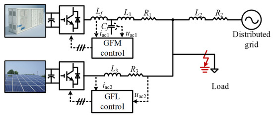
Figure 1.
Paralleled GFM and GFL DER system connected to a weak grid.
In this paper, the typical droop control is employed for the GFM DER, while the constant power control (PQ) is employed for the GFL DER.
The basic control principle of GFM control is shown in Figure 2 and (1). Basic principle of GFL control and PLL is shown in Figure 3 and (2)–(4) [20]. There are many studies that have already explained these two concepts very clearly, which we will not elaborate on here:
where fac, Uac, Pac, Qac, fn, Uacn, Pacn, and Qacn represent the real-time frequency, voltage, active power, reactive power, rated frequency, voltage, active power, and reactive power, respectively. mp and nq represent the droop coefficients, respectively.
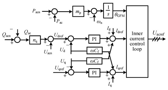
Figure 2.
Control scheme of GFM DER.
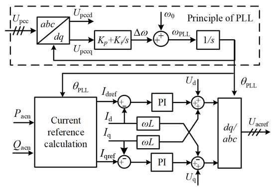
Figure 3.
Control scheme of GFL DER.
- (1)
- Principle of the PLL: When a grid-side fault occurs, the current amplitude of the GFL DER could be directly limited. Therefore, the transient process of a GFL DER is mainly determined by the phase θPLL locked by the PLL, since θPLL is used for abc/dq coordinate transformation. As shown in Figure 3, first, the PCC voltage uPCC is transmitted to the PLL module through the sampling stage. The obtained Q-axis voltage component Uq generates an angular frequency offset Δω through the PI controller. The internal angular frequency ωPLL will pass through an integration unit to generate the internal phase angle θPLL. By designing the controller parameters of the current inner loop, it is ensured that the current inner loop can achieve rapid tracking of the reference current, and its control bandwidth is much greater than that of the PLL. According to Figure 3, the mathematical equation of PLL can be expressed as follows:where ω0, Kp, Ki, and Upccq represent the rated angular frequency, PI parameters, and the Q-axis component of uPCC, respectively.
- (2)
- Definition of weak grid: In engineering, we often use the short-circuit ratio (SCR) to quantitatively assess the strength of a power grid. It is the ratio of the short-circuit capacity Ssc of the power grid to the rated capacity Prated of the generators or DERs connected to this point. It is described in the following (5):where Ssc represents the apparent power at the short-circuit point. Un and Xeq are the rated pre-fault voltage and system equivalent impedance, including the impedance of lines, transformer, and generator, respectively. Hence, the most prominent feature of a weak power grid is that the equivalent impedance of the grid side is relatively large and the short-circuit capacity is relatively small. This means that the power-supporting capacity of the system is insufficient. When there are power fluctuations or disturbances, the voltage and frequency of the power grid are more likely to fluctuate, and the system stability is relatively poor, as is concluded in Table 1.
 Table 1. Relationship of short-circuit ratio and strength of grid.
Since the extremely weak power grids are related to the rationality of power grid architecture design, this paper mainly considers the weak power grid problem when 3 ≤ SCR < 10.
2.2. Model of Paralleled System
By referring to the topology of the paralleled GFM and GFL DER system and the local control principle, Figure 4 shows the equivalent circuit of the hybrid system for a more intuitive expression. As can be observed, the terminal voltage/current of the GFM DER is represented by uac1 and iac1, which is equal to a voltage-controlled source paralleled with an impedance Z1. The terminal voltage/current of the GFL DER is represented by uac2 and iac2, which is equal to a current-controlled source. The external grid is represented by ug paralleled with an impedance Z2, and the phase of ug is also used as the phase calculation base in the following model.
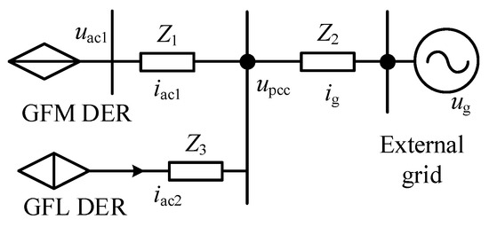
Figure 4.
Equivalent circuit of the paralleled GFM and GFL DERs connected to a weak grid.
According to Kirchhoff’s current law, the system node current equation is established as follows (6):
where Y1, Y2, and Ig are the admittance of Z1, Z2, and the grid-side current. Equation (6) reflects the voltage and current relationship among the GFM DER, GFL DER, and the external grid through the node current equation. According to (6), the current of GFL DER can be derived as follows (7):
From (6) to (7), the grid-side current Ig is eliminated, so that the current Iac2 can be expressed through measurable variables. Then, Upcc can be derived as follows (8):
By referring to the PLL principle in Figure 2, Upccq is derived through the abc/dq coordinate transformation with the phase locked by PLL when the d-axis of the grid-side voltage is employed as the basis, as is shown in the following (9):
where φ12, φ21, and φ11 are the impedance phase angles of equal paralleled lines among Z1, Z2, and Z3. φ is the phase angle of the PLL. As can be inferred by (9), Upccq is coupled with the current vector of the GFL DER iac2, the voltage vectors of the GFM DER uac1, and the external weak grid ug, while the line impedance Z1 and Z2 determine the extent of influence.
Furthermore, the power injected into the PCC by the GFL DER can be derived as follows (10):
where S2*, and Iac2*, respectively, represent the total output power of the GFL DER in the paralleled system and the conjugation of the GFL DER current. Combining (7), (8), and (10), and substituting the phases of voltage and current, the output power of the GFL DER is solved as follows (11):
As can be observed from (11), the cos(x) unit reflects the active power component, while the sin(x) unit reflects the reactive power component. As can be inferred, both the active/reactive powers are related to the current vector of the GFL DER iac2, the voltage vectors of the GFM DER uac1, and the external weak grid ug. Moreover, the line impedance Z1 and Z2 determine the extent of influence. To intuitively present the coupling degree, we define three coefficients, K1 = Z1Z2/(Z1 + Z2), K2 = Z2/(Z1 + Z2), and K3 = Z1/(Z1 + Z2), and describe the variations in these three coefficients in Figure 5 when the line impedance Z1 and Z2 change.
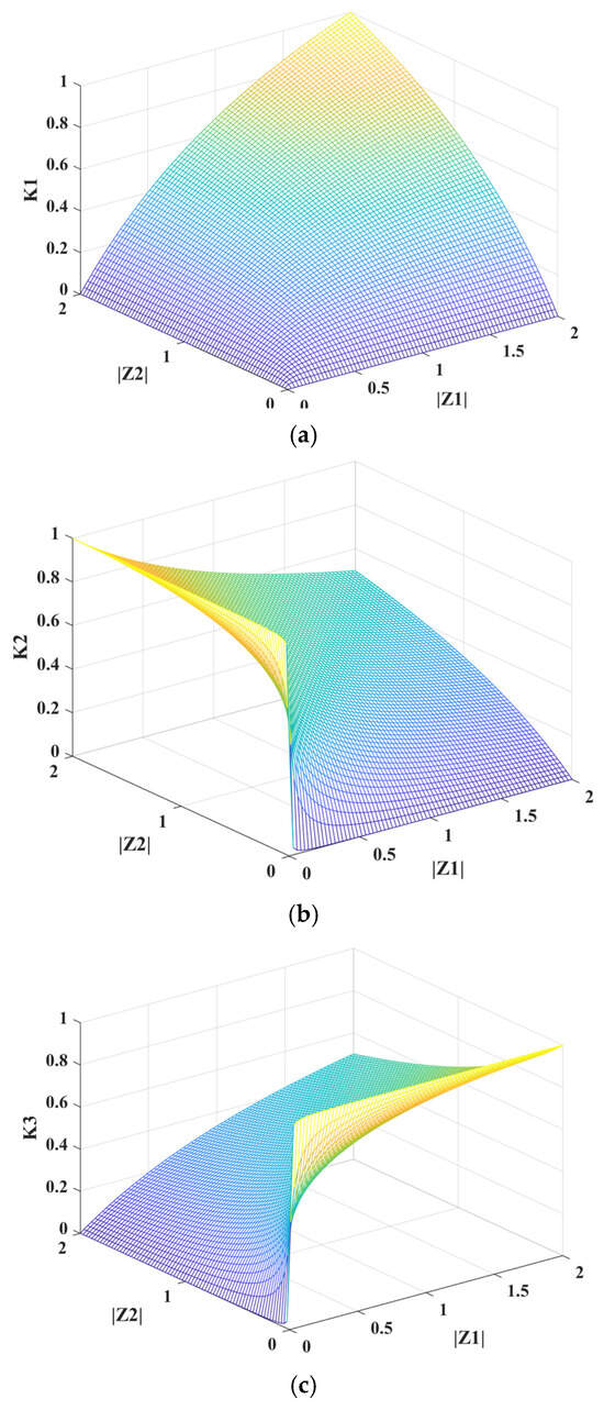
Figure 5.
Influence of different line parameters on the sensitivity of the PLL. (a) Influence of |Z1| and |Z2| on K1, (b) influence of |Z1| and |Z2| on K2, and (c) influence of |Z1| and |Z2| on K3.
As shown in Figure 5a, the change of K1 is relatively gentle with the increase of Z1 or Z2. As is described in Figure 5c, K3 will increase rapidly with the increase of Z1, but have a gentle response to changes in Z2. As is described in Figure 5b, K2 will increase rapidly with the increase of Z2, but have a gentle response to changes in Z1. It is obvious that the weak grid with a larger impedance Z2 will enlarge the coefficients K2, which denotes that the weak grid will make the Upccq and the output power of the GFL DER more sensitive to the voltage dynamics of a GFM DER. Since the transient process of a GFL DER is mainly influenced by Upccq, the coupling degree between the GFM and GFL DERs will be increased.
As is shown in (9), the voltage vector of the GFM DER and the external weak grid are related to the phase θ1 = (φ21 + δ − φ) of GFM DERs and the phase θ2 = (φ11 − φ) of the grid-side voltage. Hence, the PLL dynamics of GFL DER also depend on the phase θ2 of GFM DERs and the phase θ1 of the grid-side voltage. Under a transient state, the drastically changeable frequency of the power grid and the relatively stable frequency that GFM DER attempts to maintain will cause the Upccq of PLL to present an uncertain state between them. As is shown in (11), the output power of the GFL DER also depends on the phase θ3 = (φ21 + δ − φac2) and the phase θ4 = (φ11 − φac2). If θ3 = 0, the power coupling between the GFL DER and the GFM DER will be minimized. If θ4 = 0, the power of GFL DER will be less influenced by the grid-side voltage. Subsequently, we will further analyze the impact of these phase variations.
When the line is purely inductive, φ11 and φ21 can be regarded as 0°. According to the transient interaction model in (10), the phase angles φ of the PLL and the power angle δ of the GFM DER will increase. Due to the inertia property of GFM DER, the angular frequency ωGMF changes more slowly than ωPLL, resulting in δ changing more slowly than φ. Therefore, the value of δ − φ will gradually become negative. From θ1 = (φ21 + δ−φ), it can be known that the interval of phase θ1 is within [−π/2,0]. Moreover, the phase θ2 = (φ11 − φ) is also within [−π/2, 0], and there will be −π/2 < θ2 < θ1 < 0. The phase θ3 = (δ − φac2) is within [−π/2, π/2]. The phase θ4 = −φac2, which depends on the current phase of the GFL DER. Furthermore, Table 2 presents the system stability variations with a different power angle of the GFM and power factor angle of the GFL DER.
Table 2.
System stability variations with a different power angle of GFM and power factor angle of GFL DER when the line is purely inductive.
As can be seen in Table 2, when θ3 = 0, the GFM DER has the greatest influence on the active power of the GFL DER Pac2, but it has no influence on its reactive power. Since there are cosθ4 > 0, and sinθ4 < 0, the GFM DER’s influence is consistent with that of the grid-side voltage. Hence, at this time, the system’s transient stability could be in a middle state. When θ3 is within [0, π/2], the GFM DER’s influence on the active power of the GFL DER Pac2 is consistent with the grid-side voltage’s influence on Pac2, while the GFM DER’s influence on the reactive power of the GFL DER Qac2 is in the opposite direction to that of the grid-side voltage’s influence on Qac2. Hence, at this time, the system’s transient stability could be in a low state. When θ3 is within [−π/2, 0], the GFM DER’s influence on the active/reactive power of the GFL DER is consistent with the grid-side voltage’s influence on Pac2 and Qac2; hence, at this time, the system’s transient stability could be in a high state.
When the line exhibits resistive and inductive properties, as is shown in (9), φ21 and φ11 are less than 0°. Compared with the case where the line is purely inductive, the line impedance with resistive inductive characteristics will further narrow the error between δ and φ, but still stay within [−π/2, 0]. Therefore, θ1 and θ2 are still mainly located within the interval of [−π, 0]. Furthermore, the system’s stability varies with a different power angle of the GFM, and the power factor angle of GFL DER can be seen in Table 3. Since there are cosθ4 ∊ [−1, 1], and sinθ4 < 0, when θ3 is within [−π, 0], the GFM DER’s influence on the active/reactive power of the GFL DER is consistent with the grid-side voltage’s influence on Pac2 and Qac2; hence, at this time, the system’s transient stability could bea in high state.
Table 3.
System stability variations with a different power angle of GFM and power factor angle of GFL DER when the line exhibits resistive and inductive property.
As can be inferred from the above analysis, whether under a pure inductive or impedance network, the influence of the GFM DER voltage and the grid-side voltage on the PLL of the GFL DER is in the same direction. Moreover, in a weak grid, it is more affected by the GFM DER. At this time, the influence of the grid-side voltage will bring new harmonic interference. In addition, in both types of line networks, the system stability of is the highest when the power angle of the GFL DER is greater than the power factor angle of the GFM DER. Based on this mechanism, this paper proposes a coordinated fault ride-through method for the paralleled GFM and GFL DERs connected to a weak grid.
3. Proposed CFRT Control
3.1. Basic Principle
The principle of the proposed adaptive frequency sharing-based CFRT control method for the paralleled GFM DER and GFL DER system under weak grid is shown in Figure 6. Detailed control schemes are elaborated as follows.
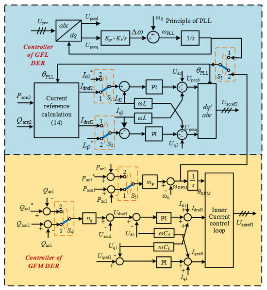
Figure 6.
Principle of the proposed adaptive frequency sharing-based CFRT control method.
- (1)
- Control scheme of GFL DER
As shown in Figure 6, under a steady state, the switches S1–S5 are in the position 1. Under a transient fault state, the switches S1–S5 are in position 2, and the current reference of the GFL DER is regulated to inject proper active/reactive power to support the PCC voltage. In this way, the power factor angle of the GFL DER will have greater maintenance than the power angle of the GFM DER. The angular frequency generated by the GFM DER is also adopted as the angular frequency reference in the GFL DER. This is because, under a weak grid, the PLL of GFL DER has a deeper coupling relationship with the voltage vector of the GFM DER compared to that with the grid-side voltage vector. But these two voltage vectors have different dynamics, which could cause the PLL to lose lock.
According to Figure 1, the terminal voltage of the GFL DER can be expressed as follows (12):
where Idq2 and Udq2 represent the terminal current and voltage of the GFL DER in the dq frame. When (12) is written in matrix form, it can be expressed as follows (13):
It was pointed out in Section 2 that, as for the CFRT issue of the paralleled GFM DER and GFL DER system, the reactive and active power injection ratio of the GFL DER should be larger than that of the GFM DER to enhance stability of the paralleled system under large disturbances. Ignoring the losses of the converter, it is assumed that the real-time output current can fully track the current reference signals through the inner-current control loop. Subsequently, the current reference of the GFL DER is regulated from the following (14):
where uα and uβ are the two components of the PCC voltage in the static αβ coordinate system, which could represent the real-time status of the grid side. In this way, the GFL DER can inject an appropriate active and reactive power ratio, making the PCC voltage more stable. Since, in the above (13), the voltage difference vector [(Ud2 − Upccd), (Uq2 − Upccq)] is in the stationary coordinate system [uα, uβ]. Therefore, if the components of the stationary coordinate system are directly adopted in the control, the measured values can be reduced and the system response speed can be improved. The middle matrix is the inverse matrix of the equivalent impedance. The component (1 − Upccpu) indicates the degree of voltage drop. When the PCC voltage is normal, this component will be 0. It will increase with the degree of voltage drop. The grid voltage components uα and uβ are directly used, which enables the control to respond quickly to changes in grid voltage and improves the system dynamics. Idqref is the steady current reference of the GFL DER, while Iqd* is the transient state current reference considering the line impedance characteristics. Upccpu is the Per-unit value. K is the proportion coefficient, which could make the maximum current amplitude Iacm less than twice the rated current Iacn.
- (2)
- Control scheme of GFM DER
The above control scheme of the GFL DER cannot enhance the transient stability of the GFM DER. In this paper, a method for changing the power reference of the GFM DER is proposed to enhance the large disturbance stability. The principle is shown in the following (15):
where Pac1*, Qac1*, and Sn1 denote the active/reactive power during a transient state and the rated apparent power of the GFM DER. As shown in Figure 7, the stability mechanism of the GFM DER can be explained by the extended equal area rule (EEAC). As shown in Figure 7, curves I, II, and III, respectively, represent the pre-fault, fault duration, and post-fault power angle curves (P − δ) of the GFM DER. According to the EEAC rule, when a grid fault occurs, the active power reference Pacn will be greater than the output active power Pac1. Therefore, the angular frequency of the GFM DER will increase. The area between the reference active power and the output active power curve is called the acceleration area, denoted as AS1. Meanwhile, the area between the reference active power and the output active power after the fault is cleared is called the deceleration area and is denoted as AS2. This occurs if there exists δmax that satisfies AS1 = AS2. Also, if δmax < δu (unstable equilibrium point), the synchronous power converter can return to the stable equilibrium point after the fault is removed. If δmax > δu, the synchronous power converter will experience transient synchronous instability. Therefore, if the active power reference could be reduced during the fault period, the acceleration area would be decreased, and the δmax value range would be larger, thereby enhancing the system stability. When it is ensured that Pacn and curve II have an intersection point, the system will have a stable equilibrium point. Therefore, in this paper, this value is taken as the reference value of the adjusted active power reference, as shown in (11). Subsequently, the reactive power reference should be modified after the active power reference is determined.
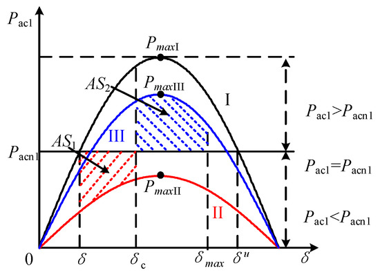
Figure 7.
P-δ of the GFM DER.
Meanwhile, the adaptive proportional current restraining method in Ref. [21] is applied in the current control loop of the GFM DER method. Since it has been elaborated in detail in Ref. [21], this will not be introduced in this paper.
3.2. Implementation Process
To better elaborate on the coordination principle of the GFM and GFL DERs, the implementation process of the proposed CFRT strategy is described in Figure 8.
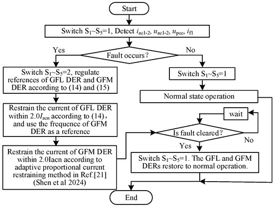
Figure 8.
Implementation flow chart of the proposed CFRT strategy [21].
Step 1: Under a steady state, the droop control and PQ control are applied in the GFM and GFL DERs, respectively. The PCC voltage and the terminal current/voltage of GFM and GFL DERs are monitored. The Switch S1~S5 is located at position 1.
Step 2: When a grid-side fault occurs and is detected by the above monitored signals. The switch S1~S5 is located at position 2. The current reference of the GFL DER is regulated according to (14), while the power references of the GFM DER are regulated according to (15).
Step 3: The real-time current of the GFL DER is restrained within twice the rated current Iacn2 through the parameter K in (14). The real-time current of the GFM DER is restrained by the adaptive-proportional current limiter and is also within 2.0 times its rated current Iacn1.
Step 4: After the fault is cleared, the grid-side voltage will return to the original state. At this time, switch S1~S5 returns to position 1, and the GFM and GFL DERs are restored to normal operation by the rated references.
4. Case Studies
To verify the effectiveness of the proposed CFRT method for the paralleled GFM and GFL DERs system under a weak grid, three groups of case studies are carried out in this section through PSCAD/EMTDC software 4.2, including (1) Case A: Theoretical Model Validation; (2) Case B: CFRT Performance Validation of Paralleled GFM and GFL DERs under Weak Grid; and (3) Case C: Comparison with the conventional method. The line parameter Z2 uses the (0.01 + j0.12 pu) and (0.038 + j0.98 pu) to simulate the strong grid and weak grid, respectively. The system topology is consistent with Figure 2. The circuits and control parameters are listed in Table 4.
Table 4.
Circuit and control parameters.
4.1. Theoretical Model Validation
Section 2 of the paper presents a transient interaction model of the paralleled GFM and GFL DERs system based on PLLs. The correctness of the transient interaction model will be verified first. The physical circuit, as shown in Figure 1, and the DER controller are established in PSCAD/EMTDC to carry out the physical power electronics simulation. The fault condition is at T1 = 2.0 s, a three-phase short-circuit fault occurs, and at T2 = 2.3 s, the fault is cleared. Then, the mathematical model in Section 2 is also established to carry out the pure numerical simulation. These two simulation results are compared in Figure 9 and Figure 10, respectively, where the blue line represents the power electronics simulation and the red line represents the pure numerical simulation.
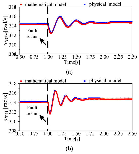
Figure 9.
Results of the power electronics simulation and the pure numerical simulation under small line impedance: (a) angular frequency of GFM DER, and (b) angular frequency of PCC voltage.
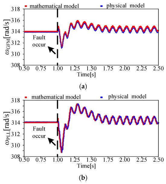
Figure 10.
Results of the power electronics simulation and the pure numerical simulation under larger line impedance: (a) angular frequency of GFM DER, and (b) angular frequency of PCC voltage.
Figure 9 shows the results under a small line impedance condition (Z2 = 0.01 + j0.12 pu, (SCR ≈ 16)). As can be observed, Figure 9a shows the angular frequency ωGFM generated inside the GFM DERs system. Figure 9b shows the angular frequency ωPLL of the PCC voltage that is locked by the PLL. It can be seen from Figure 9 that the response curve of the physical power electronics simulation results is basically consistent with the output results of the pure mathematical model in Section 2, which verifies the accuracy of the model analysis. Under the small line impedance condition, after the fault occurs, both angular frequencies will experience slight oscillations but will eventually return to stability. The minimum angular frequency of the GFM DER drops to 312.8 Hz, while the minimum angular frequency of the PCC voltage drops to 312 Hz. Compared with Figure 10, these are all within the allowable range. Moreover, due to the virtual inertia and the time scale of the voltage outer loop, the angular frequency response speed of the PLL is faster than that of the GFM DER, which is consistent with the analysis results.
Figure 10 shows the response results when the paralleled system is connected to a weak grid with a relatively larger line impedance Z2 = 0.038 + j0.98 pu, (SCR ≈ 4). With the same fault conditions, the response curves of the physical power electronics simulation results are basically consistent with the output results of the pure mathematical model. However, in this case, after the fault occurs, there are more harmonics in the PLL, and both the angular frequency of the PCC voltage locked by the PLL and the angular frequency generated inside the GFM DER experience unstable oscillations. Meanwhile, the oscillation forms of these two angular frequencies are very similar, indicating that the PCC voltage vector and the GFM DER voltage vector are deeply coupled at this time. The minimum angular frequency of the GFM DER drops to 311 Hz, while the minimum angular frequency of the PCC voltage drops to 309 Hz. This group of studies could verify the correctness of the above theoretical analysis.
4.2. CFRT Performance Validation of Paralleled GFM and GFL DERs Under Weak Grid
The case analysis results of the proposed method under the above circuit (Z2 = 0.038 + j0.98 pu, (SCR ≈ 4)) and fault conditions are shown in Figure 11. The fault condition is at T1 = 2.0 s, a three-phase short-circuit fault occurs, and at T2 = 2.3 s, the fault is cleared. As shown in Figure 11a, when T1 = 2.0 s, the grid-side voltage drops to around 70%Un. At this point, the PCC frequency drops to around 49.94 Hz due to a lack of active power, but it can remain stable. As shown in Figure 11c,d, the phase current of the GFL DER at a steady state is about 30.46 A, and the active/reactive power is approximately 20 kW and 2 kvar, respectively. After the fault occurs, the fault current amplitude of the GFL DER is within twice the current limit value, which is around 60 A. During the fault period, the active power of the GFL DER decreased to approximately 8.3 kW, while the reactive power output increased to about 13.8 kvar. After the fault is cleared, the GFL DER can smoothly transfer to the initial state.
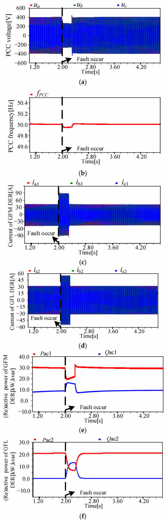
Figure 11.
Performance of the proposed CFRT control under a weak grid: (a) PCC voltage, (b) PCC frequency, (c) current of GFM DER, (d) current of GFL DER, (e) active/reactive power of GFM DER, and (f) active/reactive power of GFL DER.
As shown in Figure 11c, at the steady operating state, the current of the GFM DER is around 48 A. After the fault occurs, through the current-limiting control of the dual proportional limiter, the fault current of the GFM DER can be limited to twice the rated current (approximately 96 A). As shown in Figure 11f, the active power of the GFM DER is 30 kw, and the reactive power is about 10 kvar at steady state. During the fault period, due to the significant change in the equivalent line impedance, the active and reactive power of the GFM DER also changed, manifested as a decrease in the active power and an increase in the reactive power. With the proposed method, the reference value of the active power of the GFM DER was adjusted during the CFRT process. After the fault was cleared, no large disturbance instability occurred, and the GFM DER could also smoothly transition to a stable state, which verifies the effectiveness of the proposed CFRT control method.
4.3. Comparison with Conventional Method
To verify the operational advantages of the proposed CFRT method under a weak grid, the cooperative fault ride-through method based on switching control in Ref. [16] is compared in this section under the same fault and circuit conditions (Z2 = 0.038 + j0.98 pu, (SCR ≈ 4)).
As shown in Figure 12a, with the conventional method, a momentary voltage surge is prone to occur at the reverse switching time after the fault is cleared, which is 40% more than that of the proposed CFRT method. Comparing Figure 11b with Figure 12b, the system frequency deviation increased by 0.2%. As shown in Figure 12c,d, the conventional method can effectively limit the converter current to twice the rated current. However, after the fault is cleared, the terminal current of the GFM DER has a slight oscillation and harmonic distortions, while the terminal current of the GFL DER can remain normal. By comparing Figure 11e,f and Figure 12e,f, it is found that with the conventional method, the power response of the GFM DER is relatively slow after the fault is cleared, which is consistent with the transient overvoltage situation. Due to the oscillation and distortion of the current, the active power and reactive power of the GFM DER also oscillate, while the active power and reactive power of the GFL DER are relatively stable. But, due to the influence of power coupling on GFM DER, the power restoration time to a stable state for the GFL DER increases by 1.6 s after the fault is cleared.
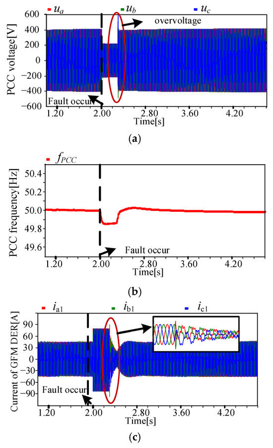
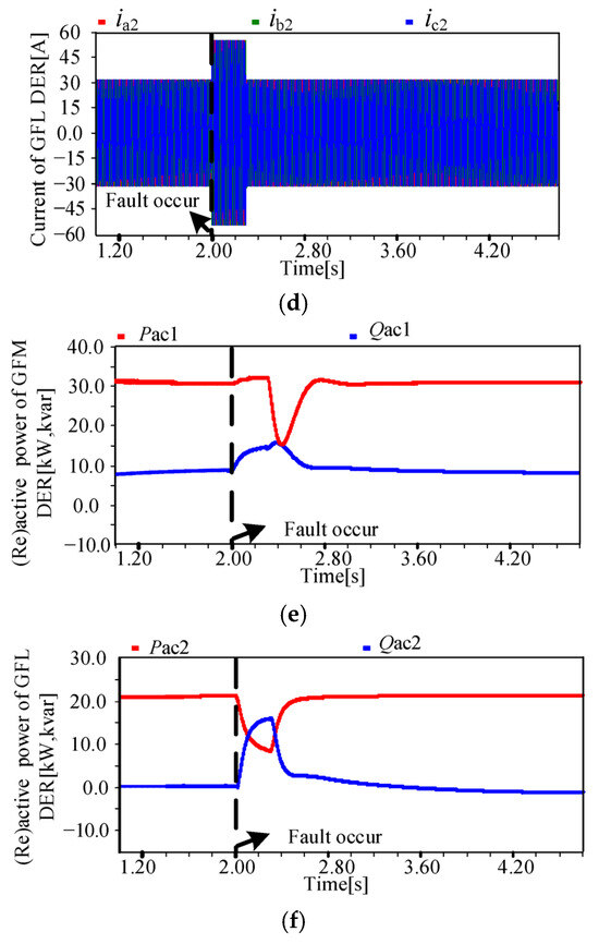
Figure 12.
Performance of conventional mode-switching-based CFRT control under weak grid: (a) PCC voltage, (b) PCC frequency, (c) current of GFM DER, (d) current of GFL DER, (e) active/reactive power of GFM DER, and (f) active/reactive power of GFL DER.
5. Conclusions
The paralleled GFM and GFL DERs system could suffer from transient instability under a weak grid. This paper investigated the transient coupling relationship between GFM and GFL DERs and proposed a CFRT control method. The main conclusions are summarized as follows:
- (1)
- When the grid-side impedance is greater, the GFL DER will be more easily affected by the GFM DER. During grid-side fault transience, the PLL of the GFL DER is prone to oscillation instability.
- (2)
- Under a transient state, in a parallel system, the GFL DER is more prone to instability than the GFM DER. The GFM DER should give priority to supporting the GFL DER, which is inconsistent with the traditional conclusion.
- (3)
- In the proposed method, during the transient period, the GFM DER shares the frequency it generates with the GFL DER. Meanwhile, both of them need to regulate the active and reactive power references to enhance the system stability.
Future prospects: This paper focuses on elaborating the transient stability issues of the paralleled GFM DER and GFL DER system connected to a weak power grid. The coupling model of the paralleled system, as well as the influence of the GFM DER’s control on the GFL DER under symmetric short-circuit faults, is studied. However, when an asymmetric fault occurs, the system’s active and reactive powers will contain oscillation components. More complex coupling influence problems will occur, respectively, in positive, negative, and zero networks. In the next stage, we will focus on investigating the issue under an asymmetric fault. Moreover, more heterogeneous GFM and GFL DERs will be considered. To be closer to the actual system, the control-hardware-in-loop (CHIL) experiments based on RTLAB will be designed for verification in the future.
Author Contributions
Conceptualization, T.T. and S.H.; methodology, Y.G. and X.S.; software, H.X.; validation, T.T.; writing—original draft preparation, T.T. and X.S. All authors have read and agreed to the published version of the manuscript.
Funding
This work was supported by the Smart Grid-National Science and Technology Major Project (2024ZD0800802), and the science and technology project of SGCC (State Grid Corporation of China): Low-carbon and Reliable Urban Power Distribution System Demonstration Project (Contract No. SGTJDK00DWJS2400298).
Data Availability Statement
The original contributions presented in the study are included in the article, further inquiries can be directed to the corresponding author.
Conflicts of Interest
Authors Tao Tan, Shengli He, Yuqin Gao were employed by the company NARI Technology Co., Ltd. The remaining authors declare that the research was conducted in the absence of any commercial or financial relationships that could be construed as a potential conflict of interest.
References
- Qu, Y.; Bai, F.; Yan, R. Adaptive Controller Based on Stability Boundaries for Grid-Forming and Grid-Following Inverters under Varying Grid Impedance. IEEE Trans. Sustain. Energy, 2025; early access. [Google Scholar] [CrossRef]
- Saha, D.; Bazmohammadi, N.; Lashab, A.; Vasquez, J.C.; Guerrero, J.M. Power and Energy Management System of a Lunar Microgrid—Part II: Optimal Sizing and Operation of ISRU. IEEE Trans. Aerosp. Electron. Syst. 2024, 60, 1376–1385. [Google Scholar] [CrossRef]
- Fan, B.; Wang, X. Equivalent Circuit Model of Grid-Forming Converters with Circular Current Limiter for Transient Stability Analysis. IEEE Trans. Power Syst. 2022, 37, 3141–3144. [Google Scholar] [CrossRef]
- Almesri, Z.M.; Hussain, H.A.; Kamel, R.M. Low Voltage Ride-Through Capability of Grid-Connected PV Systems: A Comparative Study of Grid-Following and Grid-Forming Converters Under Current Limits. IEEE Access 2025, 13, 105590–105607. [Google Scholar] [CrossRef]
- Liu, N.; Wang, H.; Zhou, W.; Song, J.; Zhang, Y.; Prieto-Araujo, E.; Chen, Z. Hybrid Frequency-domain Modeling and Stability Analysis for Power Systems with Grid-following and Grid-forming Converters. J. Mod. Power Syst. Clean Energy 2025, 13, 15–28. [Google Scholar] [CrossRef]
- Sati, T.E.; Azzouz, M.A. Optimal Protection Coordination for Inverter Dominated Islanded Microgrids Considering N-1 Contingency. IEEE Trans. Power Deliv. 2022, 37, 2256–2267. [Google Scholar] [CrossRef]
- Wu, Y.; Wu, H.; Zhao, F.; Li, Z.; Wang, X. Influence of PLL on Stability of Interconnected Grid-Forming and Grid-Following Converters. IEEE Trans. Power Electron. 2024, 39, 11980–11985. [Google Scholar] [CrossRef]
- Shen, C.; Gu, W.; Sheng, W.; Liu, K. Transient stability analysis and design of VSGs with different DC-link voltage controllers. CSEE J. Power Energy Syst. 2024, 10, 593–604. [Google Scholar] [CrossRef]
- IEEE Std 1547-2018; IEEE Standard for Interconnection and Interoperability of Distributed Energy Resources with Associated Electric Power Systems Interfaces. IEEE: New York, NY, USA, 2018; pp. 1–227.
- Liu, P.; Xie, X.; Shair, J. Adaptive Hybrid Grid-Forming and Grid-Following Control of IBRs With Enhanced Small-Signal Stability Under Varying SCRs. IEEE Trans. Power Electron. 2024, 39, 6603–6607. [Google Scholar]
- Yu, C.; Wang, Q.; Fang, W.; Wang, Y.; Diao, H.; Xu, H.; Guo, L. Research on Dynamic and Steady-State Characteristics of Grid-Following/Grid-Forming Hybrid Control Based on Model Predictive Control. IEEE Open J. Power Electron. 2025, 6, 909–918. [Google Scholar] [CrossRef]
- Han, F.; Zhang, X.; Li, M.; Li, F.; Zhao, W. Stability Control for Grid-Connected Inverters Based on Hybrid-Mode of Grid-Following and Grid-Forming. IEEE Trans. Ind. Electron. 2024, 71, 10750–10760. [Google Scholar] [CrossRef]
- Li, F.; Ma, J. Stability Studies of Grid-Forming and Grid-Following Inverter Penetrated Systems with Different External Power System Models. IEEE Trans. Power Deliv. 2024, 39, 2580–2591. [Google Scholar] [CrossRef]
- Shen, X.; Shen, C.; Huang, W.; Xu, Y. Dynamic mater-slave control strategy for transient coordination of inverter based microgrids under asymmetric faults. Int. J. Electr. Power Energy Syst. 2024, 161, 190–213. [Google Scholar] [CrossRef]
- Shen, C.; Gu, W.; Luo, E. Transient performance comparison of grid-forming converters with different FRT control strategies. Frontiers in Energy. Front. Energy 2023, 17, 239–250. [Google Scholar] [CrossRef]
- Shen, C.; Shen, X.; Zhao, B.; Chen, Z.; Zhang, X.; Lin, D.; Gu, W. Coordinated FRT Control for Paralleled Grid-Forming Converters with Enhanced Transient Stability and Current Control Flexibility. IEEE Trans. Ind. Appl. 2024, 60, 3653–3663. [Google Scholar] [CrossRef]
- Shen, C.; Shuai, Z.; Shen, Y.; Peng, Y.; Liu, X.; Li, Z.; Shen, Z.J. Transient Stability and Current Injection Design of Paralleled Current-Controlled VSCs and Virtual Synchronous Generators. IEEE Trans. Smart Grid 2021, 12, 1118–1134. [Google Scholar] [CrossRef]
- Chen, S.; Wang, Y.; Tian, Z.; Xiao, X.; Xie, X.; Gomis-Bellmunt, O. Understanding a Type of Forced Oscillation in Grid-Forming and Grid-Following Inverter Connected Systems. IEEE Trans. Power Electron. 2025, 40, 11628–11640. [Google Scholar] [CrossRef]
- Wang, S.; Jiang, A.; Ma, J.; Wang, P.; Zhang, R.; Liu, T. Transient Stability Analysis for Hybrid Parallel-Connected Converters by Two-Dimensional Phase Portrait. IEEE Trans. Power Electron. 2025, 40, 7765–7776. [Google Scholar] [CrossRef]
- Yang, C.; Huang, L.; Xin, H.; Ju, P. Placing Grid-Forming Converters to Enhance Small Signal Stability of PLL-Integrated Power Systems. IEEE Trans. Power Syst. 2021, 36, 3563–3573. [Google Scholar] [CrossRef]
- Shen, X.; Shuai, Z.; Huang, W.; Shen, C.; Shen, Y.; Shen, Z.J. Transient Characteristics and Accommodative Current Limiting Strategy for Bidirectional Interlinking Converters in Hybrid AC/DC Microgrids. CSEE J. Power Energy Syst. 2024, 10, 1575–1588. [Google Scholar] [CrossRef]
Disclaimer/Publisher’s Note: The statements, opinions and data contained in all publications are solely those of the individual author(s) and contributor(s) and not of MDPI and/or the editor(s). MDPI and/or the editor(s) disclaim responsibility for any injury to people or property resulting from any ideas, methods, instructions or products referred to in the content. |
© 2025 by the authors. Licensee MDPI, Basel, Switzerland. This article is an open access article distributed under the terms and conditions of the Creative Commons Attribution (CC BY) license (https://creativecommons.org/licenses/by/4.0/).