Abstract
With the increasing penetration of renewable energy generation, large-scale voltage dips may cause significant active power deficits and threaten system frequency stability. To address the issue, this article proposes a two-stage control strategy to enhance the frequency support capability of renewable energy plants by maximizing converter utilization during asymmetric grid voltage dips. First, a qualitative analysis of converter active power capacity considering current capacity constraints under grid faults is conducted to establish the basis for mitigating system-wide active power deficits. Second, individual phase current constraints are formulated for converters under asymmetric voltage conditions to achieve full utilization of converter capacity. Based on this, a two-stage control strategy for renewable energy plants is proposed, where plant-level convex optimization models for both pre-fault and post-fault conditions are established. By optimally allocating current references of converters within the plants, the requirement of grid codes is satisfied, and the overall frequency support capability of plants is effectively improved. Simulation results demonstrate that the proposed strategy raises the system frequency nadir from 49.58 Hz to 49.66 Hz under a minor fault and from 49.06 Hz to 49.11 Hz under a severe fault, confirming its effectiveness in enhancing the frequency support capability of renewable energy plants.
1. Introduction
With the continuous increase in the penetration of renewable energy generation, the requirement of new power systems for renewable energy plants is transitioning from “passive adaptation” to “active support” [1,2,3]. During grid faults, renewable energy plants are required not only to maintain grid connection but also to provide system support in order to mitigate the adverse impacts of grid faults.
Currently, many low-voltage ride-through (LVRT) control methods have been proposed to enhance the voltage support capability of renewable energy plants. In [4], the voltage support problem of converters was formulated as a voltage optimization issue under constraints of current, active power, and synchronization stability, with strict optimality analysis of improving the positive-sequence voltage at the point of common coupling (PCC). In [5], a model-free control method for inverter-based resources was developed to achieve optimal dynamic voltage support without requiring detailed grid parameters. In [6], a neural network (NN) control framework was proposed to effectively detects voltage sags, comprehend their characteristics, and provide support to the system by injecting reactive current according to the requirement of grid codes. In [7], coordinated control of rotor-side and stator-side active/reactive currents of a doubly-fed induction generator (DFIG) was developed, improving both DC bus voltage stability and voltage support capability. In [8], the remaining capacity of wind turbines was preferentially utilized to substitute for the output of the static var generator (SVG) in steady state, thereby ensuring sufficient reactive power reserve in the SVG for rapid voltage support during faults.
The above research mainly focuses on the voltage support of renewable energy plants under symmetric fault conditions. However, since asymmetric faults are much more common in power systems, research on the active support capability of renewable energy plants under such conditions is of greater practical significance [9,10,11]. In [12], the negative sequence current phasor was optimally distributed into its active and reactive components to achieve the minimum voltage unbalance factor and the positive-/negative-sequence current phasors were adjusted to confirm the minimum real power fluctuations. In [13], the calculation of converter current references was transformed into an easily solved second-order cone programming (SOCP) problem by changing the voltage orientation and replacing variables, and thereby the voltage unbalance factor at the PCC was reduced. In [14], a per-phase independent reactive power control strategy was proposed, where capacitive reactive power was injected into the faulted phase and inductive reactive power is absorbed from the healthy phases, and thereby the voltage of the faulted phase was effectively boosted while overvoltage in the healthy phases were suppressed. In [15], an optimization model for converters considering instantaneous active/reactive power oscillations and peak current limitation was established to achieve optimal voltage support. In [16], an optimal unbalance attenuation model was established for DFIGs considering dual-sequence coupling and was solved by SOCP, which reduced the voltage unbalance while maintaining the grid-connected stability.
The above literature mainly focuses on voltage support during grid faults but pays limited attention to frequency safety issues. When a large number of renewable energy plants simultaneously enter LVRT operation, significant active power deficits will occur, which may lead to frequency drops [17,18,19]. In [20], the frequency stability challenges of the Irish power system with high wind penetration were discussed, showing that the sudden loss of wind turbine active power during grid faults posed a greater frequency risk than conventional generator tripping.
To address the system’s frequency safety issues during low-voltage faults, some studies have sought to improve the frequency support capability of renewable energy plants during fault conditions by incorporating extra equipment. In [21], grid battery storage systems were integrated with DFIG-based wind farms to inject both active and reactive current during grid faults. In [22], a weighted active current impact index was introduced to quantify LVRT-induced active power impulse, and synchronous condensers were effectively configured to suppress the impulse. In [23], static synchronous compensators in DFIG-based wind farms were utilized to inject more reactive current during the LVRT period to enable the DFIGs to output more active power.
Considering the cost associated with such extra equipment, some studies tend to address the frequency safety issue by improving the control strategies of renewable energy plants. In [24], model predictive control (MPC) is added within the active control loop of virtual synchronous generator (VSG) and PI control link is added within the reactive control loop, which achieves fast and accurate regulation of frequency and voltage during grid faults. In [25], the traditional fixed reactive/active current priority was replaced with an adaptive optimal scheme, in which LVRT requirements and active power support are effectively balanced during faults to mitigate frequency excursion. In [26], an enhanced control method was proposed where the output of active power was maximized while ensuring equipment safety and compliance with grid codes, and proportional resonant (PR) regulators are utilized to reduce fluctuations in active power. In [27], wind turbine pitch angles were adjusted to reserve active regulation capability during LVRT to reduce sudden active power changes and suppress frequency fluctuations. In [28], a two-stage active/reactive power optimization method for symmetrical low-voltage faults was proposed, which ensured that wind farms could maintain pre-fault active power output as much as possible. In [29], a method based on an optimal power flow model was proposed, which considered both pre-fault operational constraints and post-fault transient operational constraints to determine the optimal wind power curtailment level during LVRT operation, and thereby system economy, voltage stability, and frequency stability requirements are balanced.
However, existing literature still lacks sufficient analysis of the active power output capability of converters within plants during LVRT states and fail to fully utilize the converter capacity for frequency support. Moreover, most studies focus on frequency support under symmetrical voltage dips, while only few studies focus on control strategies for renewable energy plants under asymmetric faults. To bridge the gap, this article proposes a two-stage control strategy for renewable energy plants under asymmetric voltage dips to enhance the frequency support capability by fully utilizing the converter capacity.
The main contributions of this article are as follows:
- A qualitative analysis of the active power capability of converters during voltage dips is presented to provide the basis for a scheme to mitigate system-wide active power deficits.
- Individual phase current constraints for converters under asymmetric voltage conditions are formulated to improve converter capacity utilization and increase the upper limit of active power output.
- A two-stage control strategy is proposed to enhance the frequency support capability of the renewable energy plant by maximizing the utilization of converter capacity.
The remainder of the article is arranged as follows: Section 2 analyzes the active power capability of converters during voltage dips; Section 3 derives individual phase current constraints under asymmetric voltage conditions; Section 4 illustrates the proposed control strategy; Section 5 validates the effectiveness and superiority of the strategy through two case studies; and Section 6 concludes the article.
2. Active Power Capability of Converters Under Asymmetric Grid Faults
During grid faults, the power output capability of a renewable energy plant is mainly determined by converters within the plant, and the capacity of converters is closely related to converter current limits. Therefore, this section provides a qualitative analysis of converter active power capability under grid fault conditions, taking converter current capacity constraints into account, in order to reflect the overall active power capability of the plant.
The typical control structure of a converter under asymmetric grid faults is shown in Figure 1, which includes a synchronization module, a current references generator module, and positive- and negative-sequence current control loops [30]. In the synchronization module, the phase-locked loop (PLL) provides the grid voltage angle for dq-frame decomposition [31]. In the current references generator module, the converter current references are generated according to the requirement of grid codes, while the current limiter ensures that the converter operates within its current capacity. In the positive- and negative-sequence current control loops, the dq components of the positive- and negative-sequence currents are independently regulated by PI controllers. The output voltage references from both loops are then summed and sent to the space vector pulse width modulation (SVPWM) module to drive the grid-side converter. It should be noted that this article mainly focuses on the current output characteristics of the grid-side converters in renewable energy plants. Therefore, the dynamics of the front-end devices (e.g., photovoltaic arrays or rotor-side converters of wind power generators) are not taken into account, and the following analysis is conducted under the assumption that the DC-link voltages are perfectly maintained by the front-end converters or chopper circuits [32].
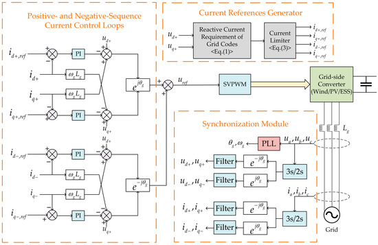
Figure 1.
The typical control structure of a converter under asymmetric grid faults.
The LVRT capability of renewable energy converters mainly consists of two aspects: the ability to remain connected to the grid under specified voltage conditions, and the ability to output reactive current. This article primarily focuses on the latter aspect. In the Chinese grid codes, the reactive current output requirements are identical for converters in wind power generation systems, photovoltaic (PV) power generation systems, or energy storage systems [1,2,3]. Therefore, the analysis in this section is suitable for all these three types of converters.
According to the grid codes, when an asymmetric fault occurs in the grid, converters are required to inject positive- and negative-sequence reactive current Iq+ and Iq− in proportion, i.e., Iq+ and Iq− should satisfy Equation (1):
where Iq,0 is the pre-fault reactive current of the converter; K+ and K− are the positive- and negative-sequence reactive current droop coefficients of the converter, respectively; U+ and U− are the positive- and negative-sequence voltages at the PCC, respectively; and IN is the rated current of the converter.
Due to the constraints of converter capacity, the total output current of the converter must not exceed its capacity limit. Neglecting the initial phase angle difference between the positive- and negative-sequence reference frames [18], the constraint is given by:
where Id+ and Id− are the positive- and negative-sequence active currents of the converter, respectively; and Imax is the maximum converter current capacity.
Since grid codes do not specify the requirements for the negative-sequence active current, the negative-sequence active current Id− is set to zero in this article to reduce the current imbalance. In addition, considering that Iq− > 0, the constraint condition in Equation (2) can be rewritten as:
When the PCC voltage experiences a severe dip, the converter may have no remaining capacity for positive-sequence active current after providing the required reactive currents, resulting in a zero maximum active power output, i.e., Pmax = 0.
In contrast, when the voltage dip is minor, the converter still retains some current capacity for positive-sequence active current after delivering the mandated reactive currents. According to Equation (3), the maximum output positive-sequence active current Id+,max of the converter is given by:
Under such conditions, the maximum active power output Pmax is:
Substituting Equations (1) and (4) into Equation (5), the maximum output active power Pmax of the converter under minor voltage dips is obtained as:
Substituting typical parameters into Equation (6) (where K+ = 1.5 p.u., K− = 1.5 p.u., Iq,0 = 0 p.u. and Imax = 1.2 p.u.) and considering a typical pre-fault active power of 0.5 p.u., the relationship between the maximum active power of the converter and the positive- and negative-sequence voltages at the PCC can be plotted, as shown in Figure 2.
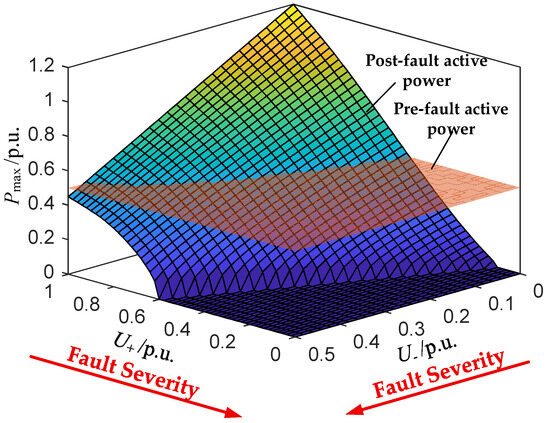
Figure 2.
The relationship between the maximum active power of the converter and the positive- and negative-sequence voltages at the PCC.
From Figure 2, the following conclusions can be drawn:
- Under severe voltage dips, the active power output of converters is significantly reduced and may even drop to zero. This leads to active power deficits in the system, which causes frequency drop and in severe cases low-frequency load shedding will be triggered.
- Under minor voltage dips, converters can maintain their pre-fault active power output, and in some cases, converters can even deliver additional active power. If the system experiences frequency drops, converters have the potential to supply extra active power to support the system frequency.
Based on the above analysis, this article proposes a compensation scheme for active power deficits under grid fault conditions. When some renewable plants are heavily affected by a fault so that their active power output is reduced due to LVRT operation, which further results in a frequency drop, the control strategy of less-affected plants can be adjusted to increase their overall active power output in order to support system frequency and enhance the frequency safety. It should be noted that such temporary active power increase requires additional energy sources within the plant, which can be provided by reserve capacity of renewable units, kinetic energy stored in wind turbine rotors, or energy storage systems.
3. Current Constraints of Converters Under Asymmetric Grid Faults
The previous analysis of the converter active power capability was based on the conventional current capacity constraints, which computes the converter total current as the scalar sum of positive- and negative-sequence currents and imposes a limit on this value. However, under asymmetric voltage conditions, the three-phase currents are also unbalanced. When the total current reaches its upper limit, it does not necessarily mean that each phase current has reached its individual limit, and thus there may still be room for increasing active current output [33]. Therefore, to improve the converter capacity utilization, it is necessary to derive the relationship between per-phase current and the positive-/negative-sequence active and reactive components, thereby obtaining a more accurate current constraint under asymmetric voltage dips. This provides a theoretical foundation to improve the control strategy.
According to the inverse Park Transformation, the magnitudes of converter active and reactive current components are related to the per-phase currents Ia, Ib and Ic as follows:
where θa+, θb+ and θc+ are the phase angle differences between the positive-sequence components of each phase currents and the positive-sequence synchronous reference frame; θa−, θb− and θc− are the corresponding angle differences for the negative-sequence components, and these satisfy the following condition:
where β is the initial phase angle difference between the positive- and negative- sequence rotating reference frames.
Expanding the expression for phase-A current yields:
By applying trigonometric angle addition formulas, phase-A current can be further rewritten as:
where
Thus, it can be concluded that the phase-A current must satisfy the following constraint:
Similarly, the phase-B and phase-C currents must satisfy:
Combining Equations (12) and (13) yields the individual phase current constraints of converters under asymmetric grid voltage dips. Compared with the conventional total-current capacity constraint in (2), adopting these individual phase current constraints ensures more effective utilization of converter capacity, thereby the active power output capability of renewable energy plants during grid faults can be further enhanced.
4. Two-Stage Control Strategy for Renewable Energy Plants Under Asymmetric Grid Voltage Dips
To maximize the utilization of converter capacity and enhance the frequency support capability of renewable energy plants during grid faults, this section proposes a two-stage frequency support control strategy, in which the active and reactive currents of each converter in the plant are optimized both before and after the fault to ensure coordinated support across all converters in the plant. In the post-fault stage, the plant’s total active power reference is adjusted to guide the plant to output more active power than under pre-fault conditions. At the same time, individual phase current constraints are adopted to guarantee full utilization of the converter capacity, thereby improving the overall active power capability of the plant.
4.1. Stage I: Pre-Fault Optimization
Communication delays are inevitable in the plant-level coordinated control due to data transmission and optimization computation. However, the proposed two-stage control strategy inherently mitigates the adverse effects of such delays. During Stage I of pre-fault control, the plant is expected to pre-calculate the current references for each converter under different fault severity levels and distribute them in advance to the converter controllers [28]. This allows converters to retrieve the corresponding current references through a look-up table method once a fault occurs, thereby enabling a timely response to compensate for the communication delay.
On the premise that the plant’s reactive current output satisfies the requirement of the grid codes, a mathematical optimization model is established to ensure that the active power output of the plant remains as close as possible to the pre-fault level by determining the positive-sequence active current, positive-sequence reactive current, and negative-sequence reactive current of each converter.
The objective function of the optimization model is:
where c1 and c2 are the weighting factors for reactive current and active power objectives, respectively; ρ is the scaling factor for reactive current; Pplant is the plant active power during the fault; Pplant,0 is the plant active power before the fault.
To prioritize the reactive current support required by grid codes during voltage dips, the weighting factors in the optimization model are set such that c1 ≫ c2 (e.g., c1 = 0.99 and c2 = 0.01). The specific values of c1 and c2 are not unique and can be tuned according to specific operation conditions. However, their ratio must be kept sufficiently large to guarantee reactive current priority. Under minor voltage dips, this objective ensures ρ = 1, and active power is optimized under this constraint. Under severe voltage dips, the objective shifts to maximizing ρ to ensure that the reactive current support requirement is satisfied.
The constraints in Stage I are as follows:
- Reactive current requirement
The plant’s positive- and negative-sequence reactive currents must satisfy the grid codes. When converter capacity cannot meet the requirement, both components should be reduced proportionally. Thus, the reactive current of the plant must satisfy Equation (15):
where Iq+,plant and Iq−,plant are the positive- and negative-sequence reactive current of the plant, respectively; and are the positive- and negative-sequence reactive current of the i-th converter, respectively; Iq,plant,0 is the reactive current of the plant before the fault; K+,plant and K−,plant are the positive- and negative-sequence reactive droop coefficients of the plant, respectively; IN,plant is the rated current of the plant; n is the number of converters in the plant.
- 2.
- Active power constraints
Under the assumption that internal active power losses within the plant are neglected, the relationship between the plant and converter active powers satisfies the following equation:
where is the positive-sequence active current of the i-th converter; Pi is the active power of the i-th converter during the fault; is the maximum available active power of the i-th converter.
To prevent excessive short-term power fluctuations, which may threaten the safety of power generation equipment, the change in each converter’s active power must be limited:
where is the maximum permissible change in active power output for the i-th converter; is the active power of the i-th converter before the fault.
- 3.
- Current capacity constraints
According to previous conclusion, three-phase separate current constraints is beneficial for enhancing the converter’s active power capability. However, since the initial phase angle difference β between the positive- and negative-sequence rotating coordinate systems is unknown before the fault, employing the three-phase separate current constraints for optimization would require traversing all possible values of β, which increases the computational burden significantly. Therefore, in Stage I, the scalar sum of the positive and negative sequence currents is used to calculate the total current of the converter to reduce the computational burden. The resulting issue of under-utilization of the converter capacity will be addressed in Stage II.
According to Equation (3), the current capacity constraint of the converter can be transformed into a second-order cone form to improve solving efficiency:
where is the maximum current capacity of the i-th converter.
In summary, the optimization model for Stage I is:
Since the objective function is quadratically convex and the constraints comprise linear equalities, linear inequalities and second-order cone constraints, the optimization model for Stage I is a second-order cone programming (SOCP) problem, which can be solved efficiently.
The flow chart of the proposed control strategy in Stage I is shown in Figure 3. During steady-state operation, the plant controller periodically (e.g., every 1–3 min) solves the optimization model for different U+ and U−. to generate current reference tables and distribute them to all converters. This enables converters to promptly look up and apply the pre-calculated references upon fault occurrence to minimize active power deviation in the early stage of the fault and consequently alleviate the frequency drop.
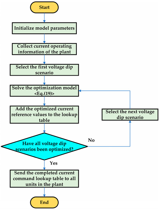
Figure 3.
The flow chart of the proposed control strategy in Stage I.
4.2. Stage II: Post-Fault Optimization
In Stage I, the conventional current constraint was used with limited converter utilization, and the plant reference power was fixed to the pre-fault level, preventing additional active power support. Therefore, in Stage II (post-fault), the plant enters real-time optimization mode to output more active power.
The transition from Stage I to Stage II is triggered immediately upon fault detection. At this point, the plant controller enters the post-fault optimization mode and starts solving the plant-level optimization problem to redistribute converter current references. However, due to the computation and communication delays, converters will operate by using the pre-calculated commands from Stage I during the initial period of the fault. Once the optimization results of Stage II are received from the plant controller, each converter will seamlessly switch to the updated current references.
As shown in Section 2, under minor voltage dips, plants can output more active power than before the fault. Consequently, after fault occurs, if a frequency drop is detected, the active power reference of the plant will incorporate a frequency droop term in order to guide additional active power output. Otherwise, the reference remains at the pre-fault level. Thus, the overall plant active power reference is:
where Dplant is the active power droop coefficient of the plant; f is the measured system frequency; fN is the rated frequency of the system.
The objective in Stage II is to minimize the deviation between plant active power and its reference while meeting the reactive current requirement of grid codes. Thus, the objective function can be:
where the criterion for determining the weighting factors c1 and c2 is the same as that in Stage I.
The constraints for Stage II are as follows:
- Reactive current requirement: Same as Equation (15).
- Active power constraints.
Similarly, the power constraints for the plant and the converters in Stage II are:
where is the active power output by the i-th converter in the last control cycle.
- 3.
- Current capacity constraints
In Stage II, the initial phase angle β is measurable. Therefore, individual phase current constraints derived in Section 3 can be applied to ensure better utilization of converter capacity. According to Equations (12) and (13), the three-phase separate current constraints for the converters can be rewritten as:
In summary, the optimization model for Stage II is:
Since the objective function is quadratically convex and the constraints comprise linear equalities, linear inequalities and quadratic inequalities, the optimization model for Stage II is a quadratically constrained quadratic programming (QCQP) problem, which can also be solved efficiently to meet real-time control requirement.
The flow chart of the proposed control strategy in Stage II is shown in Figure 4. Once a fault is detected, the plant controller will update the active power reference and solves Equation (24) in real time to optimize current references of each converter. The optimized current references will then be dispatched to converter controllers, which will track the references to deliver additional active power for frequency support.
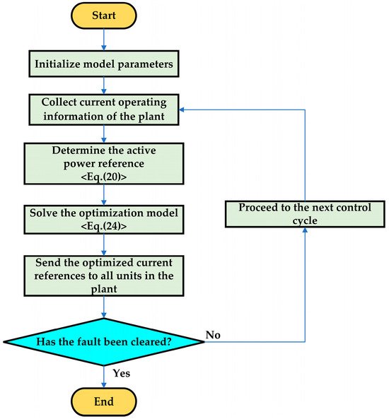
Figure 4.
The flow chart of the proposed control strategy in Stage II.
4.3. Comparison with Existing Strategies
In order to highlight the advantage of the proposed strategy, a comparison with several existing representative strategies discussed in Section 1 is presented [24,25,27,28]. As summarized in Table 1, most existing frequency-supporting strategies for renewable plants are designed for symmetric voltage dips and thus lack adaptability to the asymmetric conditions. In addition, although these strategies can provide frequency support during grid faults, they are unable to deliver additional active power beyond the pre-fault level under minor voltage dips. In contrast, the proposed control strategy enables active power compensation under asymmetric grid faults and achieves superior frequency support performance compared with existing strategies, which demonstrates its practical significance for system frequency safety.

Table 1.
Comparison between the proposed strategy and existing strategies.
5. Simulation Verification and Analysis
To validate the effectiveness of the control scheme proposed in this article, a model is built on the MATLAB/Simulink (R2024a) platform for simulation study. The simulation model includes a wind-photovoltaic-energy storage power plant and a three-phase AC power grid, as shown in Figure 5. The plant includes 30 wind power generation units rated at 2 MW, 30 PV power generation units rated at 1 MW, and 10 energy storage units rated at 1 MW. The topology and control method for each unit can be found in [34]. The AC grid can simulate voltage dips caused by short-circuit faults and can also simulate the inertial and primary frequency response to active power disturbances like synchronous generators. When a fault signal is triggered, the grid voltage amplitude U decreases to simulate a voltage dip. Meanwhile, when an active power disturbance occurs, the grid frequency f varies according to the frequency response model, reflecting the dynamic frequency behavior of the AC grid [35]. The transmission lines connect the renewable plant to the AC grid and model the impedance effects between the plant and the grid.
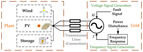
Figure 5.
Schematic diagram of the simulation system.
In simulation studies, all the wind power generation units and PV power generation units operate under maximum power point tracking (MPPT) mode. Wind power generation units can release part of their rotor kinetic energy for short-term active power boost, whereas PV power generation units do not have such capability. Energy storage units operate in discharge mode and also provide active power boost. Key system parameters are listed in Table 2. To comprehensively assess the performance of the proposed strategy, two case studies are designed. Case 1 investigates the scenario of a minor voltage dip where additional active power support is possible, while Case 2 focuses on a severe voltage dip where converter capacity is heavily constrained.
Table 2.
Key parameters of the simulation.
5.1. Case 1
The operation condition of Case 1 is that a single-phase-to-ground short-circuit fault occurs at t = 1 s, and thus phase-C voltage drops to 0.6 p.u., while phase-A and phase-B voltage remain unchanged. The fault lasts for 1.4 s. Meanwhile, other plants in the system enter deep LVRT mode, resulting in a 30 MW power deficit and a frequency drop. In this case, the PCC voltage dip is minor, and the frequency droop term added in active power reference of plant plays a major role by guiding the plant to generate additional active power. Three strategies are employed and comparatively studied: conventional unit-level autonomous response (Strategy I), the proposed strategy without frequency droop term in the power reference of plant in Stage II (Strategy II) and the proposed strategy with frequency droop term in the power reference of plant in Stage II (Strategy III). The comparison of the control structures of Strategies I to III is shown in Figure 6. To illustrate the asymmetry of the fault, Figure 7 and Figure 8, respectively, show the three-phase voltage and current waveforms at the PCC during several cycles of the fault under different control strategies. The positive-sequence reactive current, negative-sequence reactive current, active power output, and system frequency under these three strategies are shown in Figure 9, Figure 10, Figure 11 and Figure 12. The amplitudes of three-phase currents and active power outputs of each unit are given in Table 3 and Table 4. The phase current amplitudes listed in Table 3 are obtained from the measured current values at the converter terminals. The active power of each unit in Table 4 is calculated from the measured terminal voltage and current of each unit according to Equation (22).
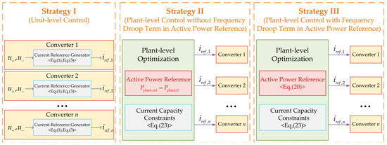
Figure 6.
The comparison of the control structures of Strategies I to III.
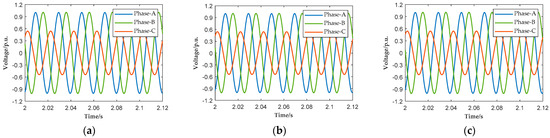
Figure 7.
The three-phase voltage waveforms at the PCC during several cycles of the fault under different control strategies: (a) Strategy I; (b) Strategy II; (c) Strategy III.
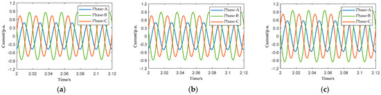
Figure 8.
The three-phase current waveforms at the PCC during several cycles of the fault under different control strategies: (a) Strategy I; (b) Strategy II; (c) Strategy III.
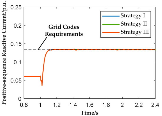
Figure 9.
The positive-sequence reactive current of the plant under different control strategies in Case 1.
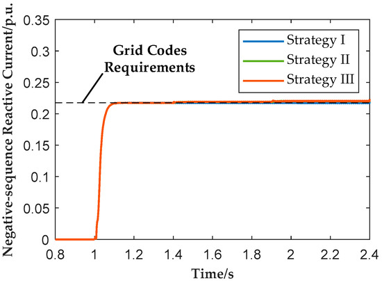
Figure 10.
The negative-sequence reactive current of the plant under different control strategies in Case 1.
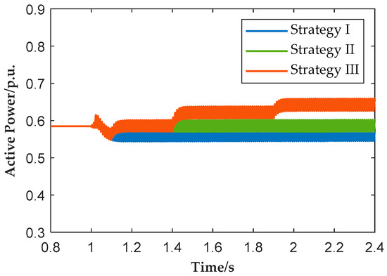
Figure 11.
The active power output of the plant under different control strategies in Case 1.
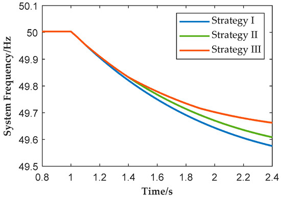
Figure 12.
The system frequency under different control strategies in Case 1.
Table 3.
The three-phase current amplitudes of each unit under different control strategies in Case 1 (p.u.).
Table 4.
The active power of each unit under different control strategies in Case 1 (p.u.).
Figure 9 and Figure 10 show that all three strategies yield similar positive- and negative-sequence reactive currents, which meets the requirement of grid codes. Table 3 indicates that the phase current amplitude of all units remains below the limit of 1.2 p.u. However, differences are clear in Figure 11 and Figure 12. Under Strategy I, active power of the plant drops to about 0.56 p.u. and frequency nadir is reduced to 49.58 Hz. Under Strategy II, active power of the plant remains around 0.58 p.u. (same as pre-fault), and frequency nadir is raised to 49.61 Hz. Under Strategy III, during the initial stage of the fault the plant’s active power output is approximately 0.58 p.u., which is the same as the pre-fault level. After 1.4 s, the Stage-II real-time control begins to take effect, increasing the plant’s active power to about 0.62 p.u. during 1.4–1.9 s and further to about 0.64 p.u. during 1.9–2.4 s, thereby raising the frequency nadir to 49.66 Hz.
Table 3 and Table 4 indicate that under Strategy I, PV power generation units must output positive- and negative-sequence reactive currents to limit their active power, while wind power generation and energy storage units maintain constant output, and thus the overall active power of plant will be reduced. Under Strategy II, PV power generation units continue to prioritize active power output and maintain values close to their pre-fault level, while the additional reactive current required by the grid is compensated by wind power generation units and energy storage units. This demonstrates the advantage of plant-level coordinated control, which allocates reactive current support among units without reducing the active power contribution of PV power generation units. Under Strategy III, on the premise of satisfying reactive current requirement, wind power generation units and energy storage units not only provide reactive current support but also further increase their active power output. As a result, the total plant active power rises above the pre-fault level, thereby providing enhanced frequency support under minor voltage dips.
5.2. Case 2
The operation condition of Case 2 is that a two-phase-to-ground fault occurs at t = 1 s, and thus phase-A and phase-B voltage drop to 0.1 p.u. while phase-C voltage remains unchanged. The fault lasts for 1.4 s. Meanwhile, other plants in the system enter deep LVRT mode, resulting in a 30 MW power deficit and a frequency drop. In this case, the PCC voltage dip is severe, so active power of the plant cannot be restored to pre-fault levels. However, since the individual phase current constraints are applied in Stage II under the proposed strategy, the active power of plant is still slightly increased to mitigate the frequency drop. Three strategies are employed and comparatively studied: conventional unit-level autonomous response (Strategy IV), proposed strategy with traditional current constraints in Stage II (Strategy V) and proposed strategy with individual phase current constraints in Stage II (Strategy VI). The comparison of the control structures of Strategies IV to VI is shown in Figure 13. To illustrate the asymmetry of the fault, Figure 14 and Figure 15, respectively, show the three-phase voltage and current waveforms at the PCC during several cycles of the fault under different control strategies. The positive-sequence reactive current, negative-sequence reactive current, active power output, and system frequency under these three strategies are shown in Figure 16, Figure 17, Figure 18 and Figure 19. The amplitudes of three-phase currents and active power outputs of each unit are given in Table 5 and Table 6. The data listed in Table 5 and Table 6 are derived in the same way as those in Table 3 and Table 4, based on the measured terminal current and voltage of each unit in Case 2.
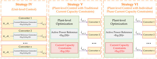
Figure 13.
The comparison of the control structures of Strategies IV to VI.
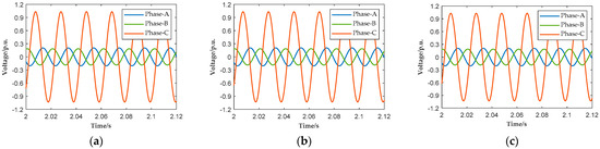
Figure 14.
The three-phase voltage waveforms at the PCC during several cycles of the fault under different control strategies: (a) Strategy IV; (b) Strategy V; (c) Strategy VI.
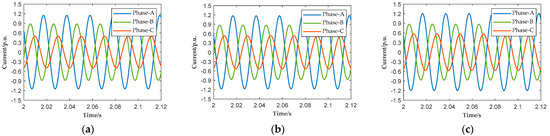
Figure 15.
The three-phase current waveforms at the PCC during several cycles of the fault under different control strategies: (a) Strategy IV; (b) Strategy V; (c) Strategy VI.
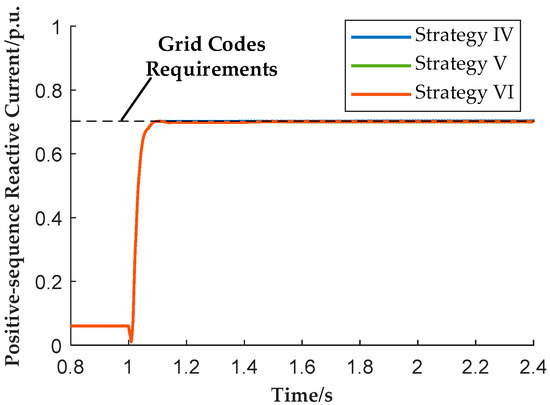
Figure 16.
The positive-sequence reactive current of the plant under different control strategies in Case 2.
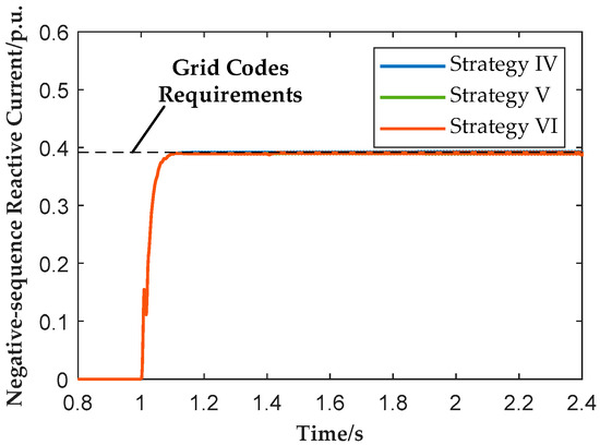
Figure 17.
The negative-sequence reactive current of the plant under different control strategies in Case 2.
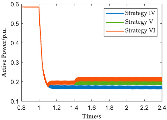
Figure 18.
The active power output of the plant under different control strategies in Case 2.
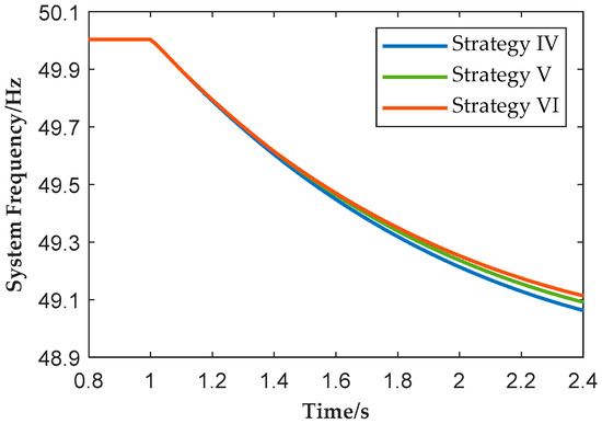
Figure 19.
The system frequency under different control strategies in Case 2.
Table 5.
The three-phase current amplitudes of each unit under different control strategies in Case 2 (p.u.).
Table 6.
The active power of each unit under different control strategies in Case 2 (p.u.).
Figure 16 and Figure 17 show that all three strategies yield similar positive- and negative-sequence reactive currents, which meets the requirement of grid codes. Table 5 indicates that the phase current amplitude of all units remains below the limit of 1.2 p.u. As shown in Table 6, due to the large reactive current demand under severe voltage dips, active power output decreases significantly in all cases. However, differences between the three strategies can still be observed from Figure 18 and Figure 19. Under Strategy IV, plant active power drops to approximately 0.17 p.u., and the system frequency nadir falls to 49.06 Hz. Under Strategy V, with plant-level coordinated control, the active power output is slightly improved to about 0.19 p.u., and the frequency nadir rises to 49.08 Hz. Under Strategy VI, by adopting individual phase current constraints, plant active power further increases to about 0.21 p.u., and the frequency nadir improves to 49.11 Hz.
Table 5 further shows that under Strategy VI, during the period of 1.4–2.4 s, phase-A current of all units reach the upper limit of 1.2 p.u., which demonstrates that the proposed constraint enables better utilization of converter current capacity. Even under severe voltage dips, the proposed strategy enables a tangible increase in active power and frequency support, from which its effectiveness in enhancing the frequency support capability of renewable plants is demonstrated.
6. Conclusions
Aiming at the issue of severe active power deficits in the system caused by large-scale renewable plants simultaneously entering low-voltage ride-through (LVRT) operation during grid faults, a two-stage control strategy is proposed to enhance the frequency support capability of renewable energy plants. The main conclusions are as follows:
- The active power capability of renewable plants under grid faults has been qualitatively analyzed. It is shown that plants less affected by faults can provide additional active power to compensate for the system-wide active power deficits. This provides theoretical guidance for setting active power references during faults.
- The limitations of conventional current constraints under asymmetric voltage conditions are highlighted, and individual phase current constraints are derived. These constraints have ensured better utilization of converter capacity under asymmetric faults, providing theoretical support for the proposed control strategy.
- A two-stage LVRT control strategy is proposed to improve the frequency support capability. By adjusting active power references, renewable plants are guided to output more active power, while individual phase current constraints ensure efficient utilization of converter capacity. Simulation results demonstrate that the proposed strategy raises the system frequency nadir from 49.58 Hz to 49.66 Hz under a minor fault and from 49.06 Hz to 49.11 Hz under a severe fault, confirming its effectiveness in enhancing the frequency support capability of renewable energy plants.
Author Contributions
Conceptualization, M.W. and C.H.; methodology, Y.W. and H.N.; software, P.L.; validation, P.L.; formal analysis, P.L.; investigation, G.Z.; resources, K.T.; data curation, P.L.; writing—original draft preparation, Z.J.; writing—review and editing, X.M. and D.S.; visualization, P.L.; supervision, X.M.; project administration, C.H.; funding acquisition, H.N. All authors have read and agreed to the published version of the manuscript.
Funding
This work was supported by Science and Technology Project of State Grid Corporation of China (SGNW0000FGJS2400319).
Data Availability Statement
The original contributions presented in the study are included in the article, further inquiries can be directed to the corresponding author.
Conflicts of Interest
Authors Penghan Li, Xiaowei Ma, Meng Wang, Chao Huo, Ying Wang, Guankun Zhao and Keqiang Tai were employed by the company Northwest Branch of State Grid Corporation of China. The remaining authors declare that the research was conducted in the absence of any commercial or financial relationships that could be construed as a potential conflict of interest.
Abbreviations
The following abbreviations are used in this manuscript:
| LVRT | Low-voltage Ride-through |
| PCC | Point of Common Coupling |
| NN | Neural Network |
| DFIG | Doubly fed Induction Generator |
| SVG | Static Var Generator |
| SOCP | Second-order Cone Programming |
| MPC | Model Predictive Control |
| VSG | Virtual Synchronous Generator |
| PR | Proportional Resonant |
| PLL | Phase-locked Loop |
| SVPWM | Space Vector Pulse Width Modulation |
| PV | Photovoltaic |
| QCQP | Quadratically Constrained Quadratic Programming |
References
- GB/T 19963.1-2021; Technical Specification for Connecting Wind Farm to Power System—Part 1: Onshore Wind Power. Standards Press of China: Beijing, China, 2021.
- GB/T 19964-2024; Technical Requirements for Connecting Photovoltaic Power Station to Power System. Standards Press of China: Beijing, China, 2024.
- GB/T 36547-2024; Technical Requirements for Connecting Electrochemical Energy Storage Station to Power Grid. Standards Press of China: Beijing, China, 2024.
- Guo, Y.; Pal, B.C.; Jabr, R.A.; Geng, H. Global Optimality of Inverter Dynamic Voltage Support. IEEE Trans. Power Syst. 2022, 37, 3947–3957. [Google Scholar] [CrossRef]
- Guo, Y.; Pal, B.C.; Jabr, R.A. Model-Free Optimal Control of Inverter for Dynamic Voltage Support. IEEE Trans. Power Syst. 2023, 38, 5860–5871. [Google Scholar] [CrossRef]
- Khan, M.A.; Kim, J. Smart Sag Detection and Reactive Current Injection Control for a PV Microgrid under Voltage Faults. Energies 2023, 16, 6776. [Google Scholar] [CrossRef]
- Luo, Y.; Yao, J.; Yang, D.; Xie, H.; Zhao, L.; Jin, R. Improved LVRT Strategy for DFIG-Based Wind Turbine Considering RSC-GSC Interaction During Symmetrical Grid Faults. IEEE Trans. Energy Convers. 2025, 40, 1674–1677. [Google Scholar] [CrossRef]
- Li, Y.; Zhu, G.; Lu, J.; Geng, H. Voltage Support Capacity Improvement for Wind Farms with Reactive Power Substitution Control. CSEE J. Power Energy Syst. 2025, 11, 999–1017. [Google Scholar] [CrossRef]
- He, L.; Li, Y.; Chu, X.; Shuai, Z.; Peng, Y.; Shen, Z.J. Single-Phase to Ground Fault Line Identification for Medium Voltage Islanded Microgrids with Neutral Ineffectively Grounded Modes. IEEE Trans. Smart Grid 2022, 13, 4312–4326. [Google Scholar] [CrossRef]
- Elkholy, A.M.; Panfilov, D.I.; Astachev, M.G. Enhancing Power System Resilience: An Analysis of Novel Arc Suppression Device Technology in Mitigating Single Line to Ground Faults. In Proceedings of the 2024 6th International Youth Conference on Radio Electronics, Electrical and Power Engineering (REEPE), Moscow, Russia, 29 February–2 March 2024; IEEE: Moscow, Russia, 2024; pp. 1–7. [Google Scholar]
- Wang, J.; Mokhlis, H.; Nadzirah Mansor, N.; Azil Illias, H.; Ramasamy, A.K.; Wu, X.; Wang, S. Smart Fault Detection, Classification, and Localization in Distribution Networks: AI-Driven Approaches and Emerging Technologies. IEEE Access 2025, 13, 141664–141693. [Google Scholar] [CrossRef]
- Abubakar, M.; Renner, H.; Schürhuber, R. Development of a Novel Control Scheme to Achieve the Minimum Unbalance Factor and Real Power Fluctuations under Asymmetrical Faults. Energies 2023, 16, 7511. [Google Scholar] [CrossRef]
- Zhao, C.; Sun, D.; Duan, X.; Nian, H. Current Reference Optimization for Inverter-Based Resources to Mitigate Grid Voltage Unbalance Factor. IEEE Trans. Power Syst. 2024, 39, 6103–6106. [Google Scholar] [CrossRef]
- Raghuraman, P.; Nath, H.; DSouza, K.; Baran, M. A New LVRT Strategy with Reactive Power Support From Inverter-Based Resources During Unbalanced Faults on a Distribution System. IEEE Trans. Ind. Appl. 2025, 61, 5868–5879. [Google Scholar] [CrossRef]
- Shabani, S.; Gholipour, M.; Niroomand, M. Improving the Performance of Grid-connected Inverters during Asymmetrical Faults and Unbalanced Grid Voltages. IET Gener. Transm. Distrib. 2024, 18, 3097–3107. [Google Scholar] [CrossRef]
- Zhang, S.; Hu, B.; Qiu, Y.; Hua, B.; Sun, D.; Nian, H. Asymmetrical Fault Ride-Through Enhancement for DFIG-Based WTs Based on Sequence Coupling Analysis. IEEE Trans. Ind. Electron. 2025, 1–11. [Google Scholar] [CrossRef]
- Lin, F.-J.; Lu, K.-C.; Ke, T.-H.; Yang, B.-H.; Chang, Y.-R. Reactive Power Control of Three-Phase Grid-Connected PV System During Grid Faults Using Takagi–Sugeno–Kang Probabilistic Fuzzy Neural Network Control. IEEE Trans. Ind. Electron. 2015, 62, 5516–5528. [Google Scholar] [CrossRef]
- Li, J.; Yao, J.; Zeng, X.; Liu, R.; Xu, D.; Wang, C. Coordinated Control Strategy for a Hybrid Wind Farm with DFIG and PMSG under Symmetrical Grid Faults. Energies 2017, 10, 669. [Google Scholar] [CrossRef]
- Tang, C.-Y.; Chen, Y.-T.; Chen, Y.-M. PV Power System with Multi-Mode Operation and Low-Voltage Ride-Through Capability. IEEE Trans. Ind. Electron. 2015, 62, 7524–7533. [Google Scholar] [CrossRef]
- O’Sullivan, J.; Rogers, A.; Flynn, D.; Smith, P.; Mullane, A.; O’Malley, M. Studying the Maximum Instantaneous Non-Synchronous Generation in an Island System—Frequency Stability Challenges in Ireland. IEEE Trans. Power Syst. 2014, 29, 2943–2951. [Google Scholar] [CrossRef]
- Gupta, S.; Shukla, A.; Abusara, M. DFIG Driven Wind Turbine with Grid Supporting Battery Storage System. IEEE Trans. Ind. Electron. 2025, 72, 1537–1548. [Google Scholar] [CrossRef]
- Wei, X.; Zhu, G.; Ding, L. Optimal Configuration Strategy of Condensers for Suppressing Large-Scale Wind Power Generation Low Voltage Ride Through Short-Time Active Power Impact. In Proceedings of the 2023 International Conference on Power System Technology (PowerCon), Jinan, China, 21–22 September 2023; IEEE: Jinan, China, 2023; pp. 1–5. [Google Scholar]
- Li, B.; Zheng, D.; Li, B.; Jiao, X.; Hong, Q.; Ji, L. Analysis of Low Voltage Ride-through Capability and Optimal Control Strategy of Doubly-Fed Wind Farms under Symmetrical Fault. Prot. Control. Mod. Power Syst. 2023, 8, 36. [Google Scholar] [CrossRef]
- Ma, C.; Sun, J.; Huang, J.; Wang, K. Transient Stability Enhancement Strategy for Islanded Microgrids Based on Energy Storage–Virtual Synchronous Machine Control. Energies 2023, 16, 6390. [Google Scholar] [CrossRef]
- Karbouj, H.; Rather, Z.H. A Novel Wind Farm Control Strategy to Mitigate Voltage Dip Induced Frequency Excursion. IEEE Trans. Sustain. Energy 2019, 10, 637–645. [Google Scholar] [CrossRef]
- Rey-Boué, A.B.; Guerrero-Rodríguez, N.F.; Stöckl, J.; Strasser, T.I. Enhanced Control of Three-Phase Grid-Connected Renewables with Fault Ride-Through Capability under Voltage Sags. Electronics 2022, 11, 1404. [Google Scholar] [CrossRef]
- Lyu, X.; Jia, Y.; Liu, T.; He, Y. Concurrent Optimal Re/Active Power Control for Wind Farms Under Low-Voltage-Ride-Through Operation. IEEE Trans. Power Syst. 2020, 35, 4956–4959. [Google Scholar] [CrossRef]
- Zhao, C.; Sun, D.; Zhang, L.; Nian, H.; Hu, B. Two-Stage Optimal Re/Active Power Control of Large-Scale Wind Farm to Mitigate Voltage Dip Induced Frequency Excursion. IEEE Trans. Sustain. Energy 2023, 14, 730–733. [Google Scholar] [CrossRef]
- Kim, S. Optimization Strategy of Wind Power Curtailment Under LVRT Operation. IEEE Access 2024, 12, 116637–116648. [Google Scholar] [CrossRef]
- Song, H.-S.; Nam, K. Dual Current Control Scheme for PWM Converter under Unbalanced Input Voltage Conditions. IEEE Trans. Ind. Electron. 1999, 46, 953–959. [Google Scholar] [CrossRef]
- Rodriguez, P.; Pou, J.; Bergas, J.; Candela, J.I.; Burgos, R.P.; Boroyevich, D. Decoupled Double Synchronous Reference Frame PLL for Power Converters Control. IEEE Trans. Power Electron. 2007, 22, 584–592. [Google Scholar] [CrossRef]
- Uehara, A.; Pratap, A.; Goya, T.; Senjyu, T.; Yona, A.; Urasaki, N.; Funabashi, T. A Coordinated Control Method to Smooth Wind Power Fluctuations of a PMSG-Based WECS. IEEE Trans. Energy Convers. 2011, 26, 550–558. [Google Scholar] [CrossRef]
- Azizi, A.; Banaiemoqadam, A.; Hooshyar, A.; Patel, M. A Blind Spot in the LVRT Current Requirements of Modern Grid Codes for Inverter-Based Resources. IEEE Trans. Power Deliv. 2023, 38, 319–334. [Google Scholar] [CrossRef]
- Bak, Y.; Lee, J.-S.; Lee, K.-B. Low-Voltage Ride-Through Control Strategy for a Grid-Connected Energy Storage System. Appl. Sci. 2018, 8, 57. [Google Scholar] [CrossRef]
- Anderson, P.M.; Mirheydar, M. A Low-Order System Frequency Response Model. IEEE Trans. Power Syst. 1990, 5, 720–729. [Google Scholar] [CrossRef]


Disclaimer/Publisher’s Note: The statements, opinions and data contained in all publications are solely those of the individual author(s) and contributor(s) and not of MDPI and/or the editor(s). MDPI and/or the editor(s) disclaim responsibility for any injury to people or property resulting from any ideas, methods, instructions or products referred to in the content. |
© 2025 by the authors. Licensee MDPI, Basel, Switzerland. This article is an open access article distributed under the terms and conditions of the Creative Commons Attribution (CC BY) license (https://creativecommons.org/licenses/by/4.0/).