1. Introduction
In recent years, with the rapid national economy, the scale of the power system has been expanding, and the characteristics of “double-high” (high proportion of renewable energy and high power electronics) have become more and more prominent, resulting in significant complexity and uncertainty in power grid operation [
1,
2,
3]. However, affected by extreme natural disasters, equipment failures, and other factors, large-scale blackouts are still difficult to avoid completely. Therefore, how to formulate an efficient black start program in advance to ensure the rapid restoration of power supply and economic losses after grid failure has become a key direction of current research [
4]. At present, after a partial blackout occurs in the power grid, it mainly relies on power plants as the restoration power source, among which hydroelectric power plants (including pumped storage power plants) are considered as the black start power source due to their flexible regulation capability [
5,
6]. However, China’s water-scarce regions such as Xinjiang and Northwest China lack such power sources, and in the event of a blackout, they can only rely on the main grid to restore power supply, resulting in a long recovery time. With the increase in new energy penetration, wind power generation has gradually become a new choice for black start auxiliary power [
7,
8,
9]. However, wind farms connected to the grid through high-voltage DC transmission need to rely on the external grid to provide a voltage reference during the start-up process, and therefore must be equipped with an auxiliary power supply to support the start-up of wind turbines and ancillary equipment. Studies have shown that WTGs equipped with auxiliary power supply can have self-starting capability and shorten the recovery time, thus enhancing the support role of wind farms during the black start process and effectively assisting in the rapid reconfiguration of the grid.
As a key means of emergency grid restoration, “black start” can assist in the rapid restoration of power supply to affected areas in the event of a large-scale grid outage, thereby minimizing the economic losses caused by the outage. The core of the technology lies in the use of the self-starting ability of the power unit, which gradually provides start-up power to other power generation equipment and ultimately recovers the entire power system in an orderly manner. In the wind–storage–diesel microgrid system, the specific process of black start is shown as follows: when the microgrid loses power due to external grid failure, the energy storage system is the first to start by virtue of its fast response capability, and supplies power to the auxiliary equipment of the thermal power plant on the opposite side of the transmission line to help the thermal power unit to gradually resume operation. With the successful grid connection of thermal power units, the recovery range of the power system can be gradually expanded until the whole power grid returns to normal operation [
10,
11].
In terms of new energy power control strategy, ref. [
12] investigated the coordinated control strategy of wind power storage through MPPT and load shedding coordinated control of the energy storage burden, to realize the reliable black start of thermal power units, and the simulation verifies that the scheme can be converted to energy storage charging and discharging. Reference [
13] proposes a variable slope voltage control strategy and nonlinear compensation sag control for the whole process of black start of wind–solar storage–thermoelectric power plant, and verifies through simulation that it can effectively inhibit the voltage shock and fluctuation, and improve the stability of the system. Reference [
14], through studying microgrid black start, proposed an optical storage microgrid black start control strategy through the improvement of the sag characteristics to achieve the zero-start boost function of the energy storage system, suppressing the transformer excitation impact, and providing stable voltage support for islanding operation. These studies provide important theoretical support and technical solutions for new energy as a black start power source, but do not consider the power synergistic control of new energy power source and energy storage in microgrids.
In terms of the configuration strategy of energy storage system, Reference [
15] investigated the LCC-HVDC-based doubly fed wind farm islanding start-up and grid-connected control strategy, and put forward a distributed energy storage configuration scheme and coordinated control method to realize black start through DC-side energy storage, and adopt reactive- and active-voltage control strategies to maintain stable operation of the system. Reference [
16] addresses the problem of energy storage capacity allocation for the participation of a combined photovoltaic storage system in black start. The black start feasibility of the system is verified by using energy storage V/f control stabilization, hybrid control of PV MPPT and load tracking, and energy storage demand. Reference [
17] establishes an evaluation system containing indicators such as storage power volatility, charging and discharging depth, etc., from the perspective of energy storage configuration optimization. The proposed model-based predictive control of a wind and light storage power coordination method, through optimization and feedback correction dynamic adjustment of wind and light storage power, effectively suppresses power fluctuations and storage demand, prevents SOC overrun, and verifies the feasibility of the wind and light storage system as a black start power source. These studies jointly optimize the overall energy storage configuration for the black start of new energy systems, but do not consider the power charge of each storage unit and the SOC constraints between storage.
This paper proposes a wind–storage–diesel joint operation cooperative black start system based on energy storage SOC equalization, which realizes the system self-recovery under the grid blackout through the orderly grid-connected control of grid-constructing energy storage, a diesel generator, grid-following energy storage, and a wind turbine. In this paper, firstly, according to the topology of wind–storage–diesel black start operation system, we analyze the whole process of wind–storage–diesel black start in combination with a thermal power unit black start; secondly, we establish the MPPT control strategy for wind power, as well as the grid-constructing VSG storage control strategy and the grid-following P/Q control strategy, and at the same time, we construct the SOC equalization control method of the two kinds of storage relative to the SOC equalization control method. At the same time, the SOC equalization control method is constructed for the two types of energy storage. Then, in the black start operation stage of wind–storage–diesel, the wind–storage–diesel power cooperative control strategy based on the SOC equalization of energy storage is constructed, which utilizes the energy storage to shave peaks and fill valleys of wind power and provides the references and support of the system and the voltage. Additionally, it adopts the equalization of the SOC method that can take care of the state of the energy storage’s own charge so as to make it not charged and discharged and to realize SOC equalization. Finally, the above control strategy is simulated by PSCAD/EMTDC V5 electromagnetic transient simulation software to verify the effectiveness of the proposed scheme.
2. Analysis of the Whole Process of Wind–Storage–Diesel Black Start System
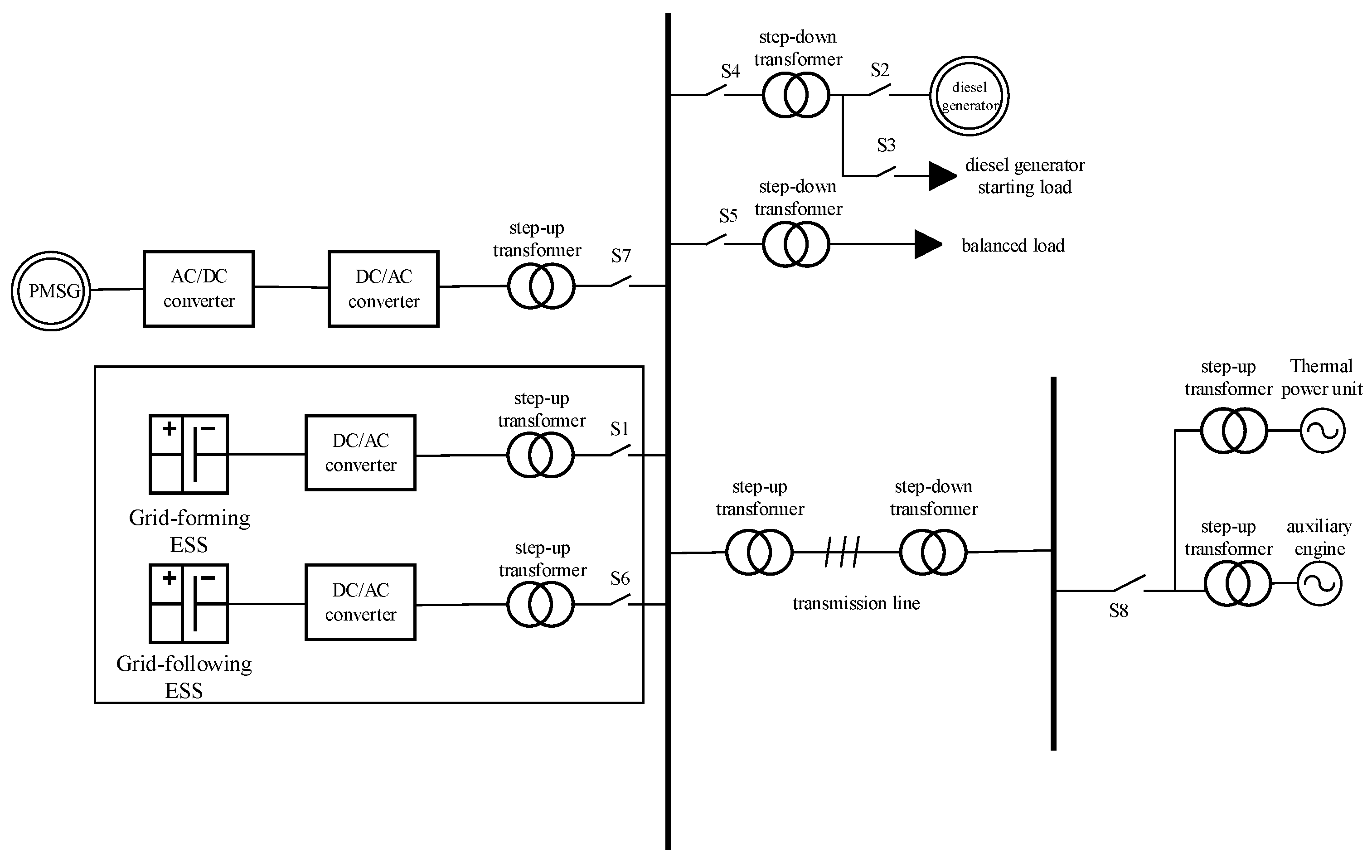
In order to analyze the whole process of wind–storage–diesel-assisted black start system, the topology of wind–storage–diesel joint operation system is established as shown in
Figure 1.
The whole process of wind–storage–diesel black start can be divided into the following steps.
(1) Initial voltage establishment phase: Close S1 and gradually establish the system voltage and frequency by adopting a zero-start boost procedure (Soft Start). The soft start is implemented by ramping up the voltage amplitude reference of the grid-forming energy storage from 0 to 1.0 per unit (p.u.) over a period of 0.5 s to prevent excessive inrush current. The established islanded network operates under the conditions of a rated voltage of 10 kV and a rated frequency of 50 Hz. Through the VSG control strategy, the external characteristics of the synchronous generator are simulated to provide voltage support, ensuring the initial stability of the islanded system.
(2) Diesel-fired grid connection and reactive power support phase: Close S2 to start the diesel generator, close S3 to put in the diesel-fired starting load after the diesel-fired outlet voltage reaches the rated value, close S4 after the diesel-fired returns to the steady state, and close S4; the grid connection is completed and the energy storage is jointly used as the balance power supply for the isolated network system. At this point, sufficient reactive power is provided to enhance the system voltage regulation capability, and at the same time, the active load of the constructed network energy storage is shared, and the SOC is consumed.
(3) Grid-connected phase of grid-following energy storage and wind turbine: Close S5 to start grid-following energy storage using P/Q control, tracking the system power demand and supporting the subsequent load and new energy access; after the system is stabilized, close S6 to put in shock loads to test the system dynamic response capability. Then, S7 is closed to start the turbine to deliver power to the high-voltage side bus via the grid-side converter. Finally, the SOC equalization method is used to maintain the SOC of the structure network and the energy storage of the following network in a stable state, while the energy storage of the following network smooths out the turbine fluctuation.
(4) Auxiliary engine start-up and thermal power unit recovery phase: The system first closes switch S8 to supply power to key auxiliary equipment such as the lubricating oil system and boiler feedwater system of the thermal power plant by starting the standby transformer. After the auxiliary equipment start-up is completed, the water vapor produced by the boiler drives the turbine, driving the generator rotor to rotate and establish the excitation magnetic field. With the establishment of the rotor magnetic field, the generator stator winding generates three-phase AC potential through electromagnetic induction, and the generated power is boosted by the main transformer and connected to the recovering grid system through the booster station. Following its successful grid connection, the thermal power unit establishes a secure foundation for system restoration. Its stable and substantial power output can significantly accelerate the recovery process, enabling the energization of a much wider section of the grid.
3. Modeling and Control Strategy of Each Power Source in a New Energy Power Plant
3.1. Control Strategy and Modeling of Grid-Configured VSG Energy Storage
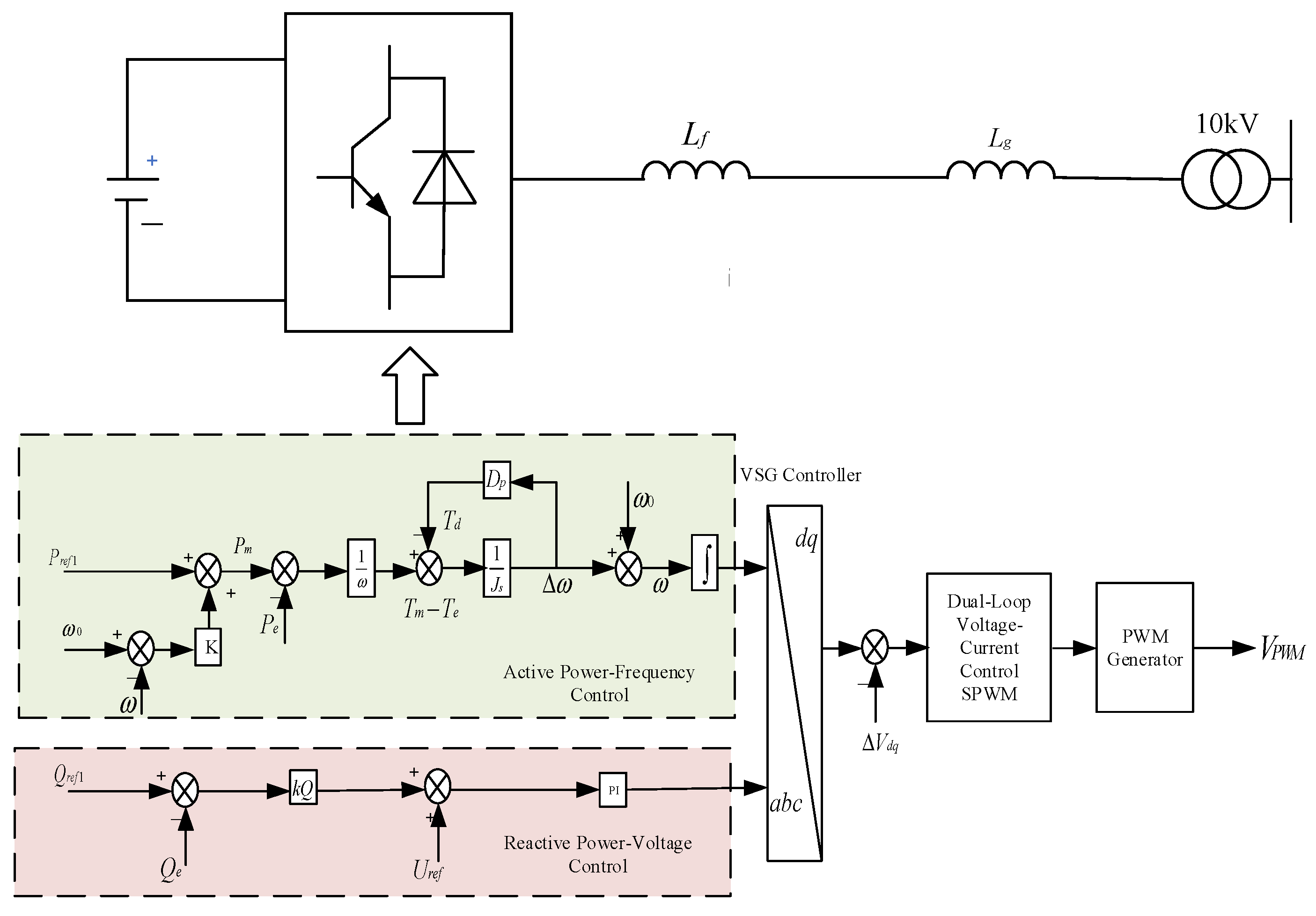
Grid-type energy storage adopts the voltage source type of operation, and its core feature is that it can independently regulate the amplitude and parameters of the output voltage. The built-in control algorithm realizes the precise adjustment of power parameters, which can maintain a stable power output. In terms of operation, it has a dual capability: on the one hand, it can operate in parallel with the public grid, and on the other hand, it can supply power independently without the support of the main grid. From the control strategy point of view, the grid-constructing converter borrows the regulation principle of synchronous generator and can complete the synchronization process without relying on phase-locked loop devices. Thanks to its unique voltage source characteristics, this system has multiple advantages in enhancing the performance of the power system: first, it can significantly enhance the short-circuit current support capability of the grid; second, it can effectively complement the system inertia response; in addition, it can improve the stability of the grid [
18], as shown in
Figure 2. The expression for the active-control of the VSG is shown in Equation (1)
In the formula, J is the virtual inertia coefficient; Dp is the damping coefficient; is a virtual power angle; Pe is the electromagnetic power of the VSG; Pm is the VSG mechanical power; is the angular velocity of VSG; is the rated angular velocity; Pref1 is the power reference value of grid energy storage; and k is the primary frequency modulation coefficient of VSG. generally varies around the rated angular velocity , so it can be considered when calculating the torque difference .
As shown in Equation (1), the VSG control endows grid-forming energy storage with key dynamic characteristics similar to conventional synchronous generators, primarily manifested in two aspects: first, it emulates the rotational inertia characteristics of synchronous machines; second, it achieves primary frequency regulation functionality. The virtual inertia (J) and damping coefficient (D) are two critical parameters that not only affect the dynamic stability of the VSG loop but also directly influence its frequency regulation capability. Based on the aforementioned model, the mathematical relationship between the VSG internal electromotive force and grid-forming energy storage power has been established.
3.2. Grid-Following Energy Storage Control Strategy and Modeling
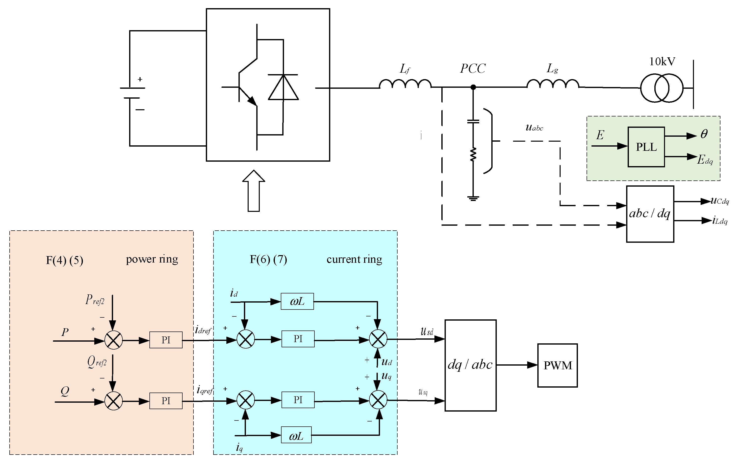
Grid-following energy storage systems operate in current-source mode, exhibiting fundamental differences in characteristics compared to grid-forming systems. These systems rely on the voltage and frequency reference provided by the grid, demonstrating strong grid dependency. Under grid-following control, the energy storage converter achieves synchronization with the main grid through phase-locking techniques. Specifically, a Phase-Locked Loop (PLL) is employed to detect the phase information at the Point of Common Coupling (PCC) in real time, adjusting the output current phase accordingly. Compared with grid-forming systems, the key advantage of grid-following energy storage lies in its fast power response capability, making it particularly suitable for mitigating instantaneous power fluctuations in the grid, thereby enhancing power supply quality and system reliability [
19].
After grid connection, the control objective of the grid-following energy storage inverter is to output the specified active and reactive power according to the microgrid’s command, i.e., the P/Q control strategy, as shown in
Figure 3. In the synchronous rotating reference frame (d-q frame), the instantaneous active power (P) and instantaneous reactive power (Q) output by the three-phase inverter are expressed as follows:
In the formula, ud, uq is the equivalent component of ua, ub, uc on the dq coordinate axis; id, iq is the equivalent component of the inductance current iaL, ibL, icL on the dq coordinate axis, respectively.
From Equation (3), it can be deduced that the command value i
dref, i
qref of the d, q axis current is as follows:
In the formula, P
ref2 is the grid-following energy storage active power reference value, and Q
ref2 is the reactive power reference value. In the synchronous rotating coordinate system, the current inner-loop control equation is as follows:
where u
sd, u
sq is the inverter reference voltage; K
p, K
i is the control parameter of the current regulator;
is the grid angle, and L
g refers to the inductance value of the grid-side inductor.
3.3. Wind Turbine Control Strategy and Modeling
According to the aerodynamic Betz theory, the power P extracted by a wind turbine from the air can be expressed as follows:
In the equation, π is the air density; R is the rotor radius; v is the wind speed; and is the power coefficient, representing the conversion efficiency from wind energy to mechanical energy. Its value depends on the tip-speed ratio, blade diameter, pitch angle, and wind speed, among which the tip-speed ratio λ and pitch angle β are the key variables determining its value.
The tip-speed ratio λ and the wind turbine rotor angular speed ω
rm are expressed as follows:
During the variable-speed operation phase below rated wind speed, since the pitch mechanism remains inactive (fixed-pitch state, β is constant), the wind turbine adjusts the rotor speed dynamically by regulating the generator torque to track the optimal tip-speed ratio λ. As a result, the power coefficient C
p can be simplified as a nonlinear function dependent solely on the tip-speed ratio:
At this point, the control system uses real-time speed to keep λ close to the optimal value, thereby maximizing wind energy capture efficiency and achieving maximum power point tracking.
Based on the relationship between wind power factor and tip speed ratio, we know that for a certain optimal tip speed ratio λ
opt, the power factor reaches its maximum value
. The maximum output power P
a-max can be expressed as follows:
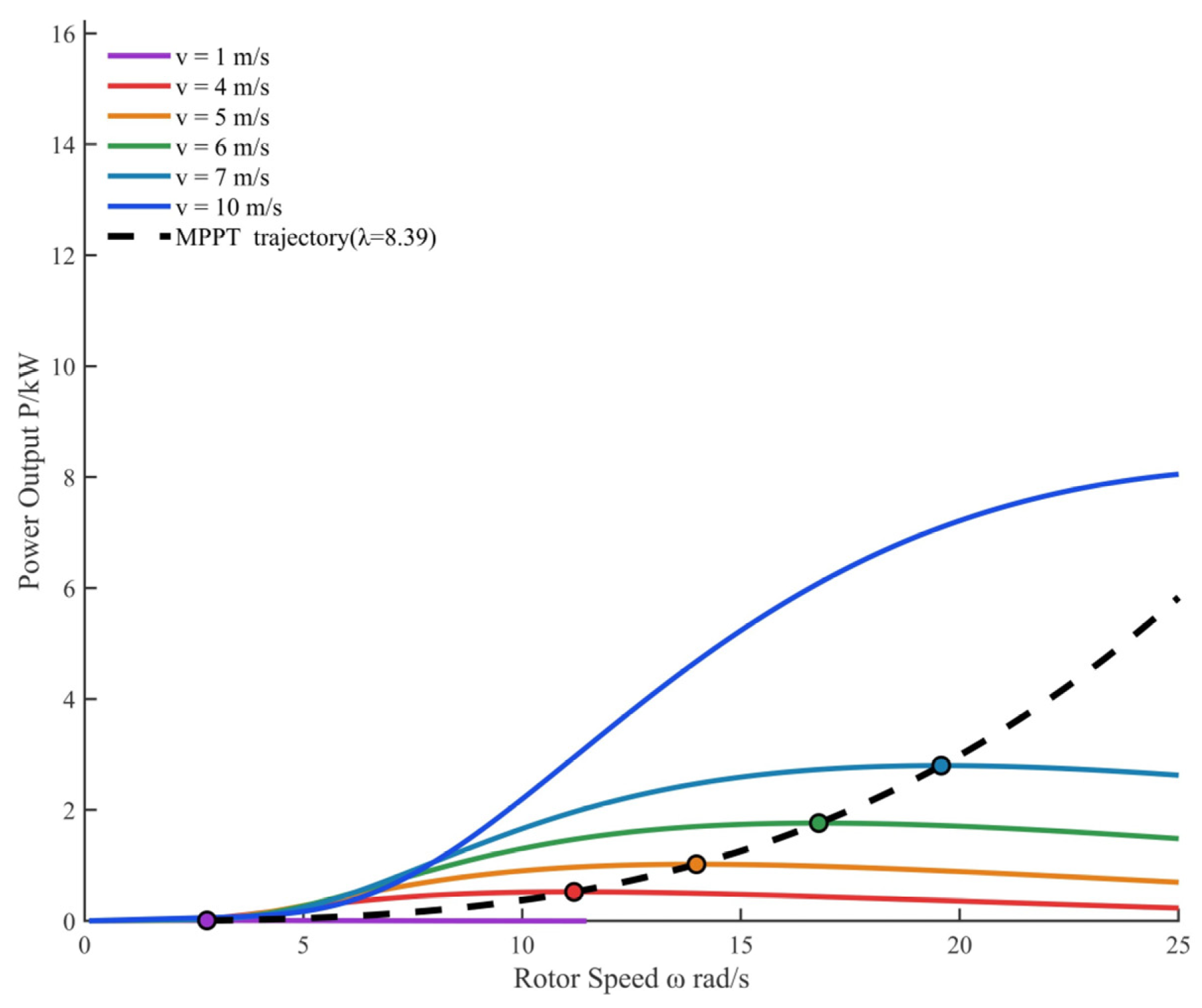
Combining Equations (9) and (11), during the variable-speed operation phase (below rated wind speed), there exists a clear functional relationship between the wind turbine’s output power and rotor speed. By extracting the maximum power points from the power curves at different wind speeds, the MPPT characteristic curve of the turbine can be obtained, as illustrated in
Figure 4. Consequently, the objective of MPPT control is to dynamically adjust the generator speed in real time, ensuring the wind turbine consistently operates along this characteristic curve. However, when the wind speed is 1 m/s, it may fall below the cut-in speed, resulting in an operational trajectory that follows a near-zero power output curve. Therefore, it is essential to set the maximum power point corresponding to the current wind speed as the reference value for the power control loop to guarantee optimal wind energy capture efficiency.
3.4. SOC Balancing
To address the shortcomings of traditional control methods in parallel energy storage systems, control parameters can be linked to the SOC of battery units to achieve reasonable power and current regulation. During the operation of parallel-connected batteries, the control system must simultaneously meet the requirements of current sharing and SOC balancing. During charging, battery units with higher SOC levels are assigned a proportionally reduced current share, while those with lower SOC receive an increased current share. Conversely, during discharging, batteries with higher SOC supply a greater current output, whereas those with lower SOC contribute less. This control strategy dynamically adjusts charge/discharge current distribution to promote SOC balance among battery units. Among them, the SOC is usually estimated using the Coulomb counting method, which tracks the state of charge of the i-th battery by real-time accumulating the charge and discharge capacity SOC
i:
In the formula, SOC
0 is the initial state of charge of the battery; C
bat is the capacity of the battery; and i
L is the output current of the battery. Define the SOC deviation of the i-th energy storage unit:
where SOC
av is the average SOC,
. The SOC deviation is then converted to a power correction value of
by the PI controller:
where K
p and K
i are proportional and integral control coefficients. Superimposing ΔP
ref,i on the original reference power P
ref1, we obtain:
When discharging (P
ref,i > 0), if ΔSOC
i > 0, then ΔP
ref,i > 0, and the output power should increase and the discharge should accelerate; conversely, for power when charging (P
ref,i < 0), if ΔSOC
i < 0, then ΔP
ref,i < 0, and the charging power avoids overcharging. Modified VSG active power sag equation is as follows:
Similarly, for a grid-following ESS, its active power output is given by the following:
In the equation, ΔPi is the power correction value converted from the SOC deviation by a PI controller. Equations (16) and (17) correspond to the SOC-based active power correction algorithms for grid-forming and grid-following energy storage, respectively. These algorithms enable the rational distribution of black start load according to energy storage capacity and achieve the dynamic balance of SOC.
4. Power Coordination Control Strategy for Wind–Storage–Diesel Hybrid Systems with Battery SOC Balancing
During the black start process of the wind storage and diesel system, the random fluctuation of wind power output will significantly affect the uncertainty of system operation. Especially in the critical stage of black start, when a large-capacity load is put into operation, the superimposed effect of this load step change and wind power fluctuation can easily cause system voltage/instability, and eventually lead to black start failure [
20].
During the black start process, the active power balance expression of the microgrid is as follows:
where P
w(t) is the wind turbine output at time t; P
ESS(t) is the active power output of the i-th energy storage distribution unit at time t; P
e(t) is the diesel generator output at time t; P
load(t) is the auxiliary machine power at time t; and 5 P
loss(t) is the system power loss at time t. This also occurs at the same time in the grid-connected stage of wind power plants. To ensure the stability of the system voltage, there are power constraints in the energy storage of the system:
In the equation, P
ESSi max is the maximum output active power of the i-th energy storage unit at time t. The microgrid reactive power balance expression is as follows:
In the formula, Qw(t) is the reactive power compensation of the fan at time t; QESS(t) is the reactive power output of the i-th energy-stored distributed unit at time t; Qe(t) is the reactive power of the diesel generator at time t; Qload(t) is the power of the auxiliary engine at time t; and Qloss(t) is the reactive power loss of the system at time t.
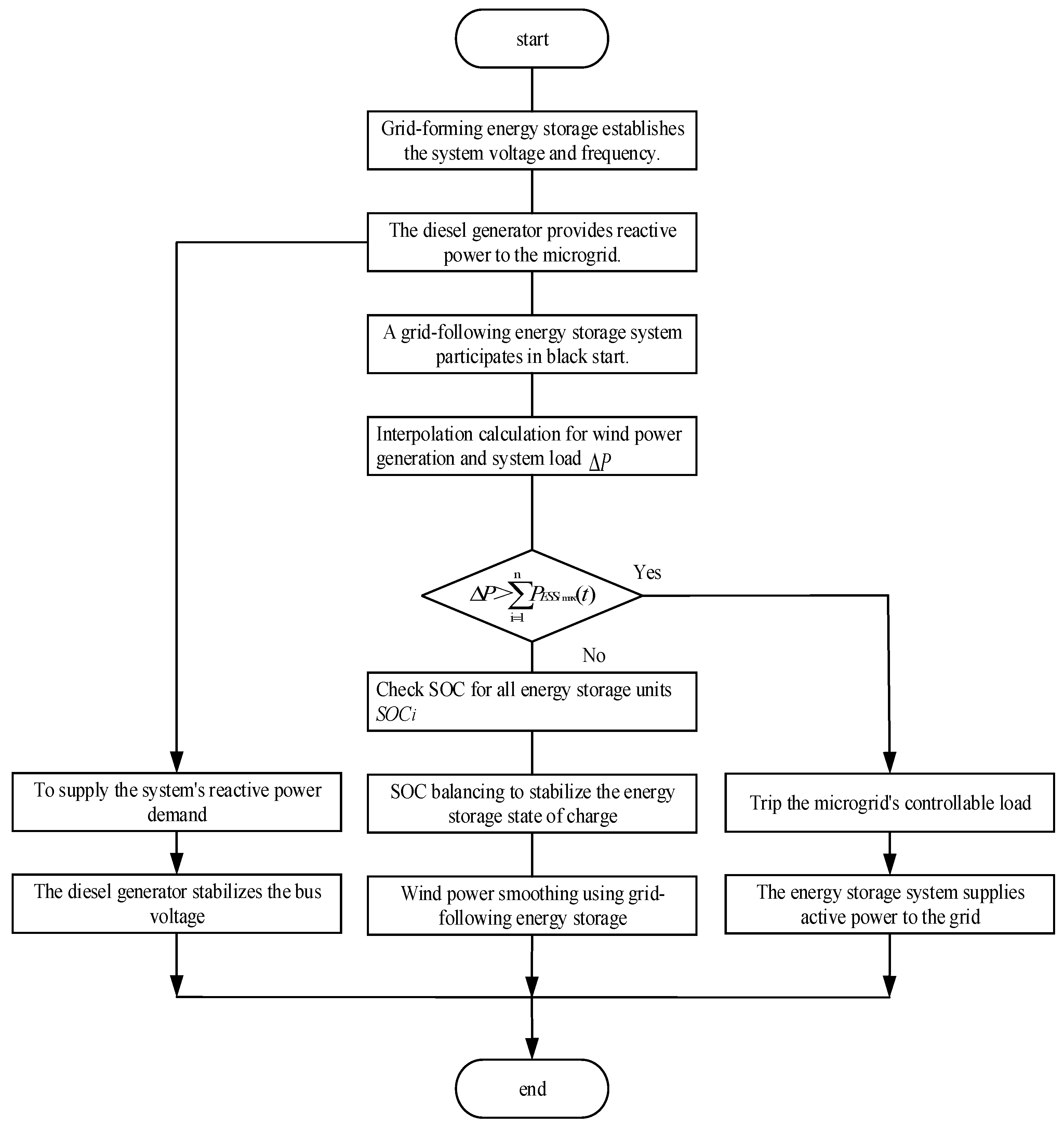
During the black start process of the wind–storage–diesel system, the energy storage system serves as a self-starting source to establish the initial voltage for the AC bus. After the diesel generator is started and synchronized with the grid, it forms a stable islanded system together with controllable loads, subsequently enabling the start-up of wind farms lacking self-start capability. When wind power output fluctuates due to wind speed variations, the ESS rapidly responds to balance active power deviations in the system. Given the load variations during black start and the complexity of coordinated control between energy storage and wind turbines, the energy storage provides dynamic support for system load changes leveraging its fast-response characteristics. During this process, issues such overcharge, over-discharge, or power limit violations may occur in the energy storage system, potentially leading to black start failure. Therefore, coordinating the active and reactive power outputs of both wind power and energy storage during black start, while maintaining the storage SOC within a reasonable range, has become a critical challenge. Addressing the system’s active and reactive power balance requirements, this paper proposes a coordinated power control strategy for the black start of the wind–storage–diesel system, with the specific scheme illustrated in
Figure 5.
The SOC state of the energy storage unit not only represents its residual electricity, but also dynamically reflects the power balance between wind farm output and black start load demand in the island microgrid. As the core of the microgrid, the SOC of the energy storage unit will directly affect the stable operation of the system once the SOC exceeds the limit. In order to ensure the smooth progress of the black start process, it is necessary to adjust the output of each unit in real time through the coordinated control mechanism of fans, diesel generators, energy storage, and loads, so as to prevent the energy storage unit from entering the working forbidden zone of overcharging or overdischarging. This multi-source coordinated control can not only maintain the SOC in the safe range, but can also ensure the uninterrupted power supply of the system, which plays a decisive role in improving the success rate of black start.
In the black start process of wind storage and diesel microgrid, the safe operation status of energy storage SOC is very important. When the SOC of grid-based energy storage and follow-up energy storage is close to the safety limit, the system automatically triggers the SOC equalization control strategy to ensure that all energy storage units are maintained within the normal operating range. At this time, follow-up energy storage mainly undertakes the function of stabilizing the active power fluctuation of wind turbines, and wind turbines usually operate in MPPT to achieve maximum wind energy capture. If the output power of the wind turbine is lower than the minimum operating requirements, resulting in an excessive power shortage, and the energy storage system cannot fully make up for the difference due to the power limitation of the converter, the system will give priority to cutting off the secondary controllable load according to the principle of load classification until the power is restored balance. In order to minimize the impact on system stability and economy, load removal follows the basic principle of secondary, first, and then important.
The SOC of the energy storage unit serves as a critical indicator in microgrid operations, reflecting not only the available energy reserve but also providing real-time insight into the power balance between wind generation and black start load demand within the isolated system. Should the SOC deviate beyond its safe operating range, system stability becomes compromised. To ensure successful black start progression, a coordinated control framework integrating wind turbines, diesel generators, loads, and energy storage is essential for real-time power regulation, thereby preventing the storage units from entering overcharge or over-discharge conditions. This multi-source coordination strategy effectively maintains the SOC within permissible limits while securing continuous power supply, playing a pivotal role in enhancing the overall success rate of system black start.
5. Results
To verify the effectiveness of the whole-process control strategy for wind–storage–diesel black start proposed in this paper, a wind–storage–diesel black start joint operation model as shown in
Figure 1 is built in the PSCAD/EMTDC V5 electromagnetic transient simulation software. This system is a simulation model established to verify the effectiveness of the control strategy, and its parameters are typical.
The system comprises a wind power generation unit, transformers, variable loads, transmission lines, an energy storage system, and a synchronous generator set. Key parameters of the system components are organized as follows:
Table 1 specifies the wind power system configuration;
Table 2 and
Table 3 detail the grid-forming VSG and grid-following energy storage systems, respectively;
Table 4 provides diesel generator specifications;
Table 5 contains transmission line parameters; and
Table 6 outlines the thermal power unit with its auxiliary systems.
The whole process of wind storage and diesel black start-up mentioned in this paper is as follows. Initially, the system is in a fully blacked-out state. From 0 to 1 s, switch S1 is closed to start the grid-forming VSG energy storage station, which establishes the system voltage and frequency through a zero-voltage start-up and boosting method. At 3 s, switch S2 is closed to connect the diesel generator. When the simulation runs to 5 s, switch S3 is closed to connect the diesel generator’s start-up load. At 8 s, switch S4 is closed to connect the diesel generator (with its start-up load) to the grid. When the simulation runs to 20 s, switch S5 is closed to connect the 1 MW primary load. At 40 s, switch S6 is closed to connect the grid-following energy storage. At 60 s, the switch is closed to connect the 2 MW secondary load. At 80 s, switch S7 is closed to start the wind farm. At 100 s, switch S8 is closed to start the auxiliary equipment.
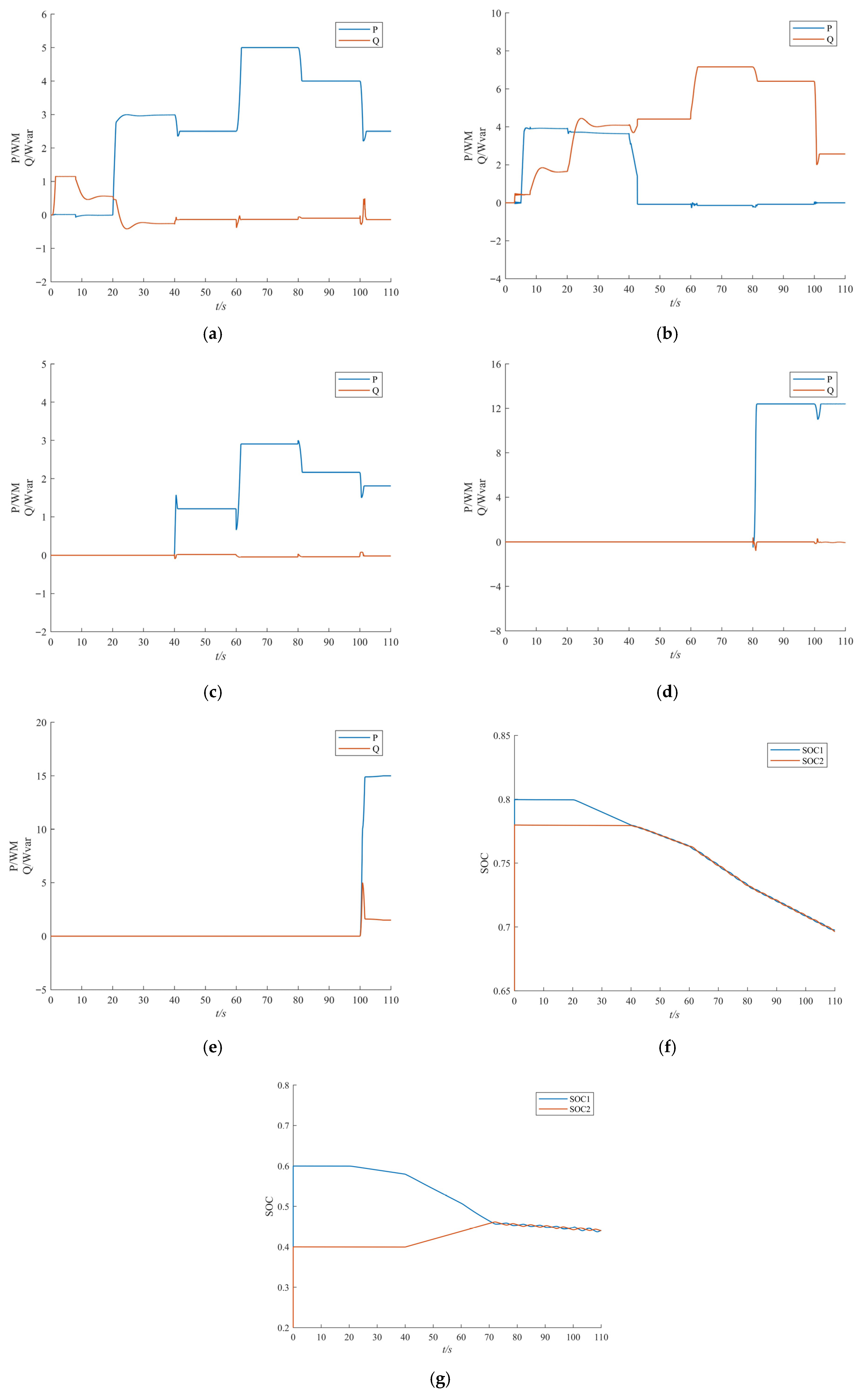
Figure 6a illustrates the active and reactive power profiles of the grid-forming ESS during the black start process of the wind–storage–diesel microgrid. The system initialization begins with a zero-start boost procedure and self-energization using VSG control to establish the AC bus voltage through no-load charging. Following stable voltage establishment, the grid-forming storage primarily maintains power balance for the black start loads.
Figure 6b presents the diesel generator’s power characteristics. The unit initiates operation at 3 s, undergoes a 5 s start-up period under gradual loading, achieves steady state at 8 s, and synchronizes to the grid. Serving as the balancing source for the islanded system, it delivers consistent reactive power support for subsequent black start load connections. The grid-following storage’s power dynamics are shown in
Figure 6c. After diesel generator synchronization, this storage unit transitions to charging mode while employing P/Q control for soft starting. Simultaneously, it implements SOC balancing coordination with the grid-forming storage.
Figure 6d displays the wind turbine’s power behavior. When commissioned at 80 s, its output fluctuations are stabilized through coordinated operation with the grid-following storage. Under MPPT control, the turbine achieves over 12 MW output post-synchronization, supplying reliable power for subsequent black start loads and extending the restoration scope. Thermal plant auxiliary systems’ power characteristics are documented in
Figure 6e. At 100 s, the integrated wind–storage–diesel system successfully energizes the station auxiliaries, enabling thermal unit start-up preparation. Throughout the black start process, both grid-forming and grid-following storage systems distribute active power loads according to their respective SOC levels. As demonstrated in
Figure 6f (where SOC1 represents grid-forming and SOC2 grid-following storage states), the SOC-based coordinated control strategy ensures gradual convergence of the storage systems’ charge states, thereby guaranteeing successful black start implementation. As shown in
Figure 6g, we adjusted the initial SOC of the two energy storage units to 0.6 and 0.3, respectively. After the grid-following energy storage unit is activated at 40 s, its SOC continues to rise and it operates in the charging state due to the constraint of SOC balancing. After 70 s, the SOC values of the two energy storage units gradually converge to a balanced state, and both units discharge continuously to maintain the normal operation of the system while enabling their SOC to gradually tend to be consistent.
In order to verify the superiority of the control strategy proposed in this paper, the following comparison schemes are designed:
Scheme 1: Adopt the control strategy of this paper;
Scheme 2: Adopt conventional sagging control strategy.
As shown in
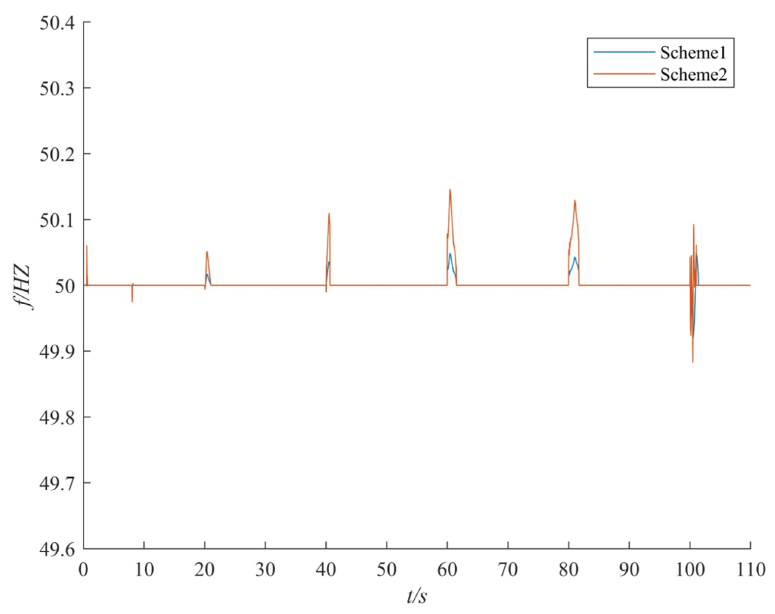
Figure 7, during the black start process, the system faces fluctuations in multiple key links. The data corresponding to
Figure 7 is presented in
Table 7. Whether it is the zero-start step-up process of the grid-forming energy storage system, the grid-connected operation of diesel generators, the commissioning of wind power systems, or the start-up process of auxiliary units of thermal power units, it will cause disturbances to varying degrees. By comparing the performance of the two schemes, it can be seen that although Scheme 2 theoretically has better adjustment capability, its actual suppression effect is not the case: at the moment of grid connection with the grid-forming energy storage, the frequency rises to 50.16 Hz; when the auxiliary unit of the thermal power unit starts, the frequency drops sharply to 48.86 Hz, and there is an obvious oscillation phenomenon throughout the whole process. In contrast, the control strategy proposed in this paper shows good frequency stabilization performance: when the diesel generator and wind power system are put into operation, the system frequency is always stable within 50.05 Hz; even in the start-up stage of the auxiliary unit of the thermal power unit, the frequency deviation can be strictly controlled within the range of 0.1 Hz, realizing the effective adjustment of the whole process of black start.
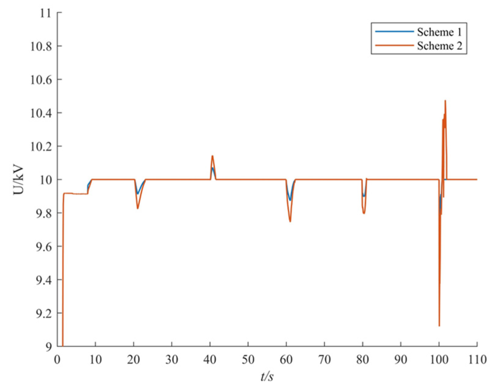
As shown in
Figure 8, voltage fluctuation also occurs during the black start voltage construction and voltage stabilization process, and the system parameters corresponding to its bus voltage waveform are presented in
Table 8. Scheme 2 has poor voltage regulation performance: when the auxiliary units of thermal power units are put into operation, the voltage overshoot reaches 0.88 kV; in addition, the grid connection of wind power will also cause obvious voltage fluctuations. Especially at the moment when the auxiliary units of thermal power units are put into operation, the voltage sags due to the sudden change in reactive power, and voltage oscillation occurs during the recovery process. In contrast, the scheme proposed in this paper successfully realizes the whole-process voltage stability control through the reactive power support of diesel generators: whether it is the grid connection of grid-forming energy storage, wind power grid connection, or the start-up of auxiliary units of thermal power units, the system voltage can remain stable, effectively avoiding the problems of voltage overshoot and oscillation, and the voltage overshoot range is within 0.5 kV, providing reliable voltage support for the wind–storage–diesel black start system.
6. Discussion
Previous research has established the feasibility of using renewable energy with storage for black start procedures, often focusing on high-level system control or overall storage configuration. However, these approaches typically do not address the critical need for dynamic power coordination among distributed sources and storage units within a microgrid, particularly the real-time balancing of SOC across individual storage units. This study fills this gap by proposing a coordinated black start control strategy for a wind–storage–diesel microgrid. The main contributions are as follows:
(1) A Hierarchical Control Framework: The strategy establishes coordinated control among grid-forming storage, diesel generation, grid-following storage, and wind turbines. This ensures system stability by decoupling tasks: storage units mitigate wind power fluctuations and stabilize frequency, while the diesel generator provides voltage support.
(2) Dynamic SOC Balancing: A key innovation is the SOC-aware control, which dynamically adjusts the power of each storage unit based on its individual charge level. This rationalizes the load distribution during black start, prevents over-stressing any single unit, and enhances the overall resilience and longevity of the storage system.
While the simulation results validate the effectiveness of the proposed strategy, several practical implementation challenges need to be considered for future real-world applications.
(1) Since the simulation results clearly demonstrate the superiority of the proposed strategy over conventional sag control, it is insightful to discuss its position relative to other advanced black start control strategies reported in the literature. For instance, Model Predictive Control (MPC) [
17] offers excellent performance for pre-defined scenarios through optimization but demands high computational resources and an accurate system model, which can be challenging to guarantee during the highly uncertain black start process. In contrast, the proposed VSG-based SOC-balancing strategy provides a more computationally efficient and robust solution, as it does not rely on a precise system model for its core operation. Compared to other heuristic methods like fuzzy logic control, our approach offers a more straightforward implementation and deterministic performance. The key distinction and contribution of this work remain the seamless integration of real-time SOC balancing into the grid-forming/grid-following control paradigm, a feature that is not commonly addressed in the aforementioned strategies. Therefore, the proposed method presents a compelling alternative that balances performance, robustness, and practical implementability for microgrid black start.
(2) The coordinated control relies on communication for exchanging SOC data and setpoints. However, communication may be prone to delays and potential packet losses, which could temporarily degrade the performance of the SOC balancing algorithm; the control strategy assumes ideal power converters. In reality, the switching dynamics, dead-time effects, and current/voltage saturation limits of converters may restrict response speed and accuracy; the SOC estimation based on the Coulomb counting method is inherently susceptible to cumulative errors caused by current sensor inaccuracies and uncertainties in the initial SOC.
(3) Regarding the recovery strategy after extreme events, we will need to establish the necessity of formulating resilience-oriented recovery plans in future work. Such plans should prioritize the protection of critical infrastructure, incorporate reinforcement measures against future disasters, and emphasize the importance of conducting cost–benefit analyses, designing market participation mechanisms for recovery services, and clarifying necessary regulatory reforms to incentivize investments in microgrids with black start capability.
Future research will implement this strategy on a Hardware-in-the-Loop (HIL) testbed to evaluate its robustness under these non-ideal conditions and develop compensation mechanisms.
7. Conclusions
This paper develops a coordinated control strategy for black start operation in a wind–storage–diesel microgrid, incorporating dynamic battery SOC balancing. Through real-time regulation of charge/discharge power across storage units and orchestrated dispatch of diesel generation and wind power, the system achieves autonomous recovery from total blackout. The principal findings are summarized below:
(1) The developed control framework successfully enables system self-energization and subsequent cranking of thermal power units. Leveraging both grid-forming and grid-following energy storage systems as black start sources, the strategy facilitates wind farm integration and expands restoration boundaries. System load support is accomplished through complementary power generation features of the hybrid wind–storage–diesel configuration.
(2) The control strategy comprehensively considers the interplay between wind power, energy storage, diesel generation, and load. Grid-forming and grid-following storage controls are used to mitigate wind power fluctuations and stabilize active power and frequency, while the diesel generator provides stable reactive power and voltage support. This integrated approach prevents black start failure caused by frequency or voltage limit violations.
(3) The designed control schemes for the grid-forming storage VSG and the grid-following storage (constant P/Q control) operate based on their individual SOC levels. This ensures rational allocation of the black start load according to their available energy capacity while simultaneously achieving SOC balance among the storage units.
