Article

Multiphysical Coupling Analysis of Sealing Performance of Underground Lined Caverns for Hydrogen Storage

1
China Petroleum Pipeline Engineering Co., Ltd., Langfang 065000, China
2
School of Civil and Transportation Engineering, Hebei University of Technology, 5340 Xiping Road, Beichen District, Tianjin 300401, China
*
Authors to whom correspondence should be addressed.
Processes 2025, 13(11), 3716; https://doi.org/10.3390/pr13113716
Submission received: 12 October 2025 / Revised: 14 November 2025 / Accepted: 15 November 2025 / Published: 18 November 2025
(This article belongs to the Topic Green Mining, 3rd Edition)

Abstract

The accurate analysis of the sealing performance of underground lined cavern hydrogen storage is critical for enhancing the stability and economic viability of storage facilities. This study conducts an innovative investigation into hydrogen leakage behavior by developing a multiphysical coupled model for a composite system of support structures and surrounding rock in the operation process. By integrating Fick’s first law with the steady-state gas permeation equation, the gas leakage rates of stainless steel and polymer sealing layers are quantified, respectively. The Arrhenius equation is employed to characterize the effects of temperature on hydrogen permeability and the evolution of gas permeability. Thermalmechanical coupled effects across different materials within the storage system are further considered to accurately capture the hydrogen leakage process. The reliability of the established model is validated against analytical solutions and operational data from a real underground compressed air storage facility. The applicability of four materials—stainless steel, epoxy resin (EP), ethylene–vinyl alcohol copolymer (EVOH), and polyimide (PI)—as sealing layers in underground hydrogen storage caverns is evaluated, and the influences of four operational parameters (initial temperature, initial pressure, hydrogen injection temperature, and injection–production rate) on sealing layer performance are also systematically investigated. The results indicate that all four materials satisfy the required sealing performance standards, with stainless steel and EP demonstrating superior sealing performance. The initial temperature of the storage and the injection temperature of hydrogen significantly affect the circumferential stress in the sealing layer—a 10 K increase in initial temperature leads to an 11% rise in circumferential stress, while a 10 K increase in injection temperature results in a 10% increase. In addition, the initial storage pressure and the hydrogen injection rate exhibit a considerable influence on airtightness—a 1 MPa increase in initial pressure raises the leakage rate by 11%, and a 20 kg/s increase in injection rate leads to a 12% increase in leakage. This study provides a theoretical foundation for sealing material selection and parameter optimization in practical engineering applications of underground lined caverns for hydrogen storage.

1. Introduction

With the global energy structure shifting to low-carbon and renewable sources, hydrogen energy—an acknowledged clean, efficient secondary energy carrier—has become a core carbon-neutrality strategy [1]. Underground hydrogen storage (UHS) is among the most promising hydrogen storage solutions due to its high capacity, low energy consumption, and inherent compatibility with renewable energy systems [2].
The properties of hydrogen molecules (ultra-small size, high diffusivity, extremely low viscosity) pose considerable challenges to sealing system design and maintenance [3,4]. Primary UHS configurations include salt caverns, aquifers, depleted hydrocarbon reservoirs, and lined rock caverns (LRCs) [5]. Salt caverns use salt rock’s dense, low-permeability structure for sealing, aquifers rely on caprocks’ low permeability, and depleted reservoirs leverage existing sealing systems. However, all three have notable geographical limitations, restricting regional adaptation [6,7,8]. By contrast, emerging LRC storage overcomes these constraints and offers high pressure-bearing capacity, a short cycle period, and strong compatibility [9].
LRC facilities for compressed air energy storage (CAES) and underground hydrogen storage (UHS) share fundamental operational similarities, including thermodynamic processes and cycling mechanisms. Despite differing working media, CAES research has yielded a mature theoretical framework and established engineering practices. Technical advances in CAES cavern design, operational control, and safety assurance offer valuable insights applicable to lined hydrogen storage development [10]. In terms of theoretical research, Kim et al. [11] conducted modeling and simulation based on thermomechanical coupling theory, and found that the permeability of concrete linings and surrounding rock affects the airtightness of storage caverns. Additionally, they noted that air leakage can be prevented if the air entry pressure of the lining exceeds the operating pressure and the water content is high. Allen et al. [12] pointed out that the leakage rate of CAES during a single injection–extraction cycle must be controlled to within 1%; otherwise, economic efficiency will be severely compromised. Wu et al. [13] established a thermal–hydraulic–mechanical (THM) coupling model to investigate the influence of parameters such as rock permeability on leakage from unlined CAES caverns. Rutqvist et al. [14] used TOUGH-FLAC simulator to simulate leakage caused by radial cracks in linings, and observed a daily leakage rate of approximately 0.16%. In research on sealing layer materials, Qin et al. [15] considered the effect of high pressure and found that the airtightness of polymer sealing layers is regulated by multiple factors, including operating pressure and temperature, and so optimizing relevant parameters can reduce the leakage rate. Zhou et al. [16] demonstrated through experiments that butyl rubber (IIR) has the lowest permeability and is therefore a preferred sealing material.
However, these studies only focus on compressed air storage caverns. Since hydrogen has unique physical properties compared to air—greater heat generation and higher pressure rise during compression—their findings cannot be directly applied to UHS [17]. Thus, to advance UHS engineering applications and the theoretical framework, scholars have conducted targeted research. In the context of numerical modeling, Hu et al. [18] built a multiphysical field coupling model comparing UHS and CAES, finding that cavern temperature/pressure variations are similar; however, hydrogen reaches higher post-charging temperatures/pressures. The ideal gas assumption may also overestimate parameters, and sealing layer/lining stresses differ. Antoine Bachand et al. [19] developed a validated open-source numerical model for UHS heat exchange and parameter prediction, noting that heat transfer affects hydrogen density, that thermal perturbation penetration is limited (needing multilayer simulation), and that flow rate regulation is key for controlling temperature peaks. Wei et al. [20] constructed a THM coupling model for LRC-UHS, enabling realistic temperature/pressure simulation. Liu et al. [21] proposed a new model integrating gas equations, heat transfer models, and hydrogen thermophysics, finding that heat transfer models minimally impact temperature/pressure, that injection/extraction temperature/pressure correlates with flow rate, that long-term storage pressure drops relate to flow rate and duration, and that pressure may drop 5–15% per cycle. Still, the aforementioned studies all fail to fully consider the occurrence mechanism of hydrogen leakage during the operation of hydrogen storage caverns, and the omission of this critical factor will lead to non-negligible deviations in the research results. Beyond modeling, sealing layer material selection is critical. In previous studies, EVOH (ethylene–vinyl alcohol copolymer) is renowned for its excellent gas barrier properties, while PI (polyimide) possesses both outstanding thermal stability and mechanical properties [22,23]. Both materials exhibit ideal potential for use as sealing layer materials. Sun et al. [24] used pilot test data to simulate rock mass parameter variability and hydrogen embrittlement on steel linings, finding that the S355 lining has significant hydrogen diffusion after ~2 months. Although cracks grow little in 10 years, S355 may cause excessive leakage, so stainless steel is recommended. Gajda et al. [25] measured epoxy resin (EP) (with admixtures) hydrogen permeability, comparing it with stainless steel and salt rock. They concluded that EP is preferred for UHS seals due to its high temperature resistance, mechanical robustness, chemical stability, and sealing effect. Nevertheless, specialized research on polymer materials as sealing layers remains relatively scarce. Existing studies are mostly confined to the screening of material properties, lacking systematic simulation analysis and in-depth exploration. Furthermore, there are still significant gaps in targeted research on the impermeability performance and mechanical response of sealing layers in lined underground hydrogen storage (UHS) worldwide.
To fill the research gap in hydrogen leakage behavior and sealing material performance for underground lined cavern hydrogen storage, this study numerically investigates the hydrogen leakage process in LRC-UHS by developing a multiphysics coupled model for a composite system of support structures and surrounding rock in the operation process. The model integrates hydrogen leakage dynamics and sealing layer mechanical properties during operation, and incorporates thermomechanical coupling via Fick’s first law, the sealing layer steady-state gas permeation equation, and the Arrhenius equation (for the effect of temperature on hydrogen permeability), aiming to accurately capture the hydrogen leakage behavior. It further evaluates four sealing materials—stainless steel, EP, EVOH, and PI—and systematically investigates key operating parameters (initial temperature/pressure, hydrogen injection temperature and injection-production rate) affecting sealing layer performance. The results are expected to provide theoretical support for material selection and parameter optimization in practical underground hydrogen storage in lined caverns.

2. Governing Equations

2.1. Gas Thermodynamics Within the Cavern

The operational cycle of a lined rock cavern UHS system consists of four successive stages (Figure 1). In the initial injection phase 0 ~ t 1 , continuous hydrogen injection makes the cavern gas mass increase continuously, and the gas mass rises steadily, as shown in the graph. Then comes the first storage plateau t 1 ~ t 2 , during which the gas mass remains constant while the injection is suspended. Next is the production phase t 2 ~ t 3 , where the controlled discharge of high-pressure gas leads to a gradual decrease in the cavern gas mass. Finally, t 3 ~ t 4 is the second hydrogen storage stage, and during this period, the gas mass stays unchanged.
For the thermodynamic behavior within the cavern, the governing equations are adopted [26,27] as follows:
V d ρ d t = F i + F e m ˙ c m 1 t
V ρ c v d T d t = F i m ˙ c h i h + Z R T ρ u ρ | T + F e m ˙ c Z R T ρ u ρ | T m 1 t Z R T ρ u ρ | T + Q ˙
F i = 1   C h a r g i n g 0   O t h e r w i s e , F e = C D   D i s c h a r i n g   0   O t h e r w i s e    
c v = c v 0 , h i h = c p 0 T i T , u ρ | T R T 0 2 Z T 0 ρ 0
p = Z R T ρ
where V   is the volume of the storage cavern, m3, ρ   is the density of hydrogen within the cavern, kg/m3, t is the operational time, s , F i represents the dimensionless periodic function for gas injection, F e represents the dimensionless periodic function for gas production, m 1 ( t ) is the hydrogen mass leakage rate from the cavern, k g / s , c v is the constant-volume specific heat capacity of the gas, J / ( k g · K ) , T   is the temperature of the gas within the cavern, K , m ˙ c is the gas mass flow rate of the compressor, k g / s , h i is the enthalpy of the injected gas, J / k g , h is the enthalpy of the gas, J / k g , Z is the gas compressibility factor, R is the gas constant, J / ( k g · K ) , u is the specific internal energy of the gas, J / k g , Q ˙ is the heat transfer rate at the cavern wall surface, J / s , C D   is the ratio of injected gas mass flow rate to produced gas mass flow rate, c p is the constant-pressure specific heat capacity of the gas, J / ( k g · K ) , T i is the temperature of the injected gas, K , Z T 0 is the partial derivative of the gas compressibility factor with respect to temperature at the initial state, and p is the pressure within the cavern,   M P a .
Due to the extremely high storage pressures within the cavern, the ideal gas assumption becomes invalid, necessitating the consideration of real gas behavior. For a real gas, the gas compressibility factor can be expressed as [18]
Z = 1 9 p 128 p c T c T 6 T c 2 T 2 1
where p c   is the gas pressure at the critical state, M P a , and T c is the gas temperature at the critical state, K .
At the cavern boundary, heat exchange occurs between the stored gas and the cavern wall through convection and conduction. To simplify calculations, an average heat transfer coefficient is employed to characterize the thermal exchange process at the cavern wall. The total heat transfer rate across the cavern surface can be expressed as
Q ˙ = h c A c T r 0 , t T t
where h c is the convective heat transfer coefficient between the gas in the cavern and the surrounding rock, W / ( m 2 · K ) , A c is the contact area between the storage cavern and the surrounding rock, m 2 , T r 0 , t is the temperature at the cavern wall surface, K , r 0 is the radius of the cavern, m , and T t is the temperature of the gas within the cavern, K .

2.2. Gas Leakage and the Effect of Temperature on Permeable Property

Quantifying hydrogen leakage through a stainless steel sealing layer via Fick’s first law [28],
J = D c
where J is the diffusive flux, m o l / m 2 · s , D is the diffusion coefficient, m 2 / s , and c is the concentration gradient, m o l / m 4 .
Considering that hydrogen leakage from an underground lined rock cavern is a very slow and minimal process, the leakage can be regarded as a steady-state process. Integrated with Sieverts’ law [29], Fick’s first law of diffusion can be modified to obtain
J = D · c x D · c 1 c 2 L = D · S · ( p 1 p 2 ) L = k · ( p p o u t ) L
m 1 t = J · A c · M
where c 1 and c 2 are the hydrogen concentrations at the inner and outer boundaries of the sealing layer, m o l / m 3 , respectively, L is the thickness of the sealing layer, m , S is the solubility coefficient, m o l / m 3 · P a , p 1 and p 2 are the hydrogen partial pressures at the inner and outer boundaries of the sealing layer, P a , respectively, p o u t is the gas pressure on the outer side of the sealing layer, P a , k is the permeability coefficient of stainless steel, m o l · m 1 · s 1 · P a 0.5 , and M is the molar mass of hydrogen, k g / m o l .
When polymeric materials are employed as the sealing layer, the steady-state gas permeation equation for polymeric membranes is applied [30],
m 1 t = ρ s · A C · P · p p o u t L
where P is the permeability of the polymeric material, ( m 3 S T P · m · m 2 · s 1 · P a 1 ) , and ρ s is the density of air at 273.15   K under standard atmospheric pressure, k g / m 3 .
Accounting for the influence of temperature on the permeable property the material, the temperature dependence of the permeable property is characterized using the Arrhenius equation [31],
k = k 0 exp E p R T   o r   P = P 0 exp E p R T
where k 0 is the initial permeability coefficient of the stainless steel m o l · m 1 · s 1 · P a 0.5 , P 0   is the initial permeability of the polymeric material ( m 3 S T P · m · m 2 · s 1 · P a 1 ) , and E p is the activation energy, k J / m o l .

2.3. Heat Transfer Around the Cavern

In this study, heat transfer within the sealing layer, the lining layer, and the surrounding rock mass of the cavern requires simultaneous consideration. The governing equation for heat conduction can be expressed as
ρ j c p j T j t = · λ j T j   j = 1,2 , 3
where ρ j is the density of the j -th layer medium, k g / m 3 , c p j is the constant-pressure specific heat capacity of the j -th layer medium, J / ( k g · K ) , k j is the thermal conductivity of the j -th layer medium, J / ( m · s · k ) , and T j is the temperature of the j -th layer medium, K . Here, the subscript indices ( j = 1, 2, 3) correspond to the sealing layer, lining layer, and surrounding rock, respectively.

2.4. Thermomechanical Deformation of the Sealing Layer

In this study, the stress-displacement behavior of the sealing layer is governed by the classical thermoelasticity theory, nut mechanical damage modes induced by stress have not been incorporated within the scope of this preliminary analysis;
· σ = F v
σ σ 0 = C : ε ε 0 ε T
ε T = α T T 0
ε = 1 2 u T + u
where σ is the Cauchy stress tensor, P a , σ 0 denotes the initial in situ stress tensor, P a , F v represents the body force vector per unit volume, N , C is the fourth-order elasticity tensor, the operator ‘:’ signifies the double-dot product (tensor contraction), ε is the infinitesimal strain tensor, ε 0 is the initial strain tensor, ε T is the thermal strain tensor, and α is the coefficient of thermal expansion, K 1 .

3. Model Validation

3.1. Validation Against Analytical Solutions

This section verifies the numerical model’s reliability through comparison with Xia’s [32] analytical thermodynamic solution for compressed air storage in lined caverns. The comparison confirms model accuracy. Extending Kushnir’s thermodynamic governing equations for caverns, Xia derived a computational method for temperature/pressure distributions using modified Bessel functions and Laplace transforms. Two simplifying assumptions were adopted as follows: (1) The thermal resistance of the sealing layer is neglected, assuming uniform temperature distribution equivalent to the lining’s inner surface temperature. (2) The surrounding rock and lining are homogenized into a single medium with concrete’s thermal properties.
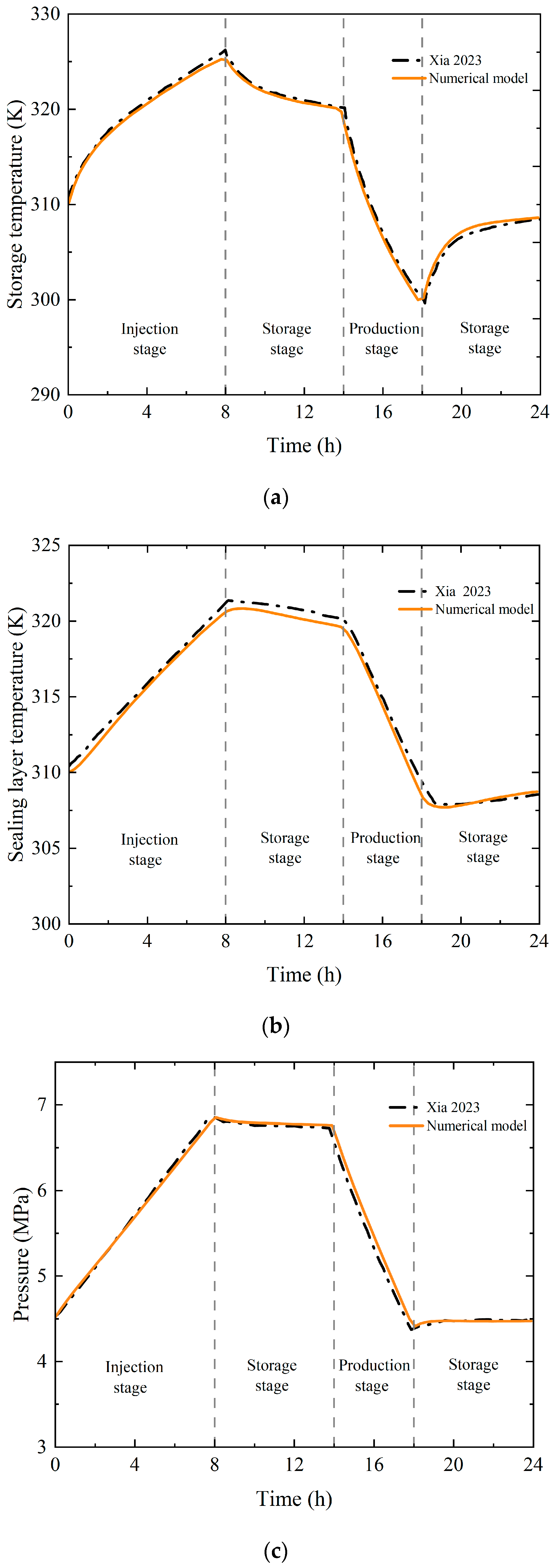
The simulation parameters exactly replicate those in the analytical solution (Table 1, Table 2 and Table 3) [18,32]. Figure 2 presents comparative results, showing dynamic temperature fluctuations in the cavern and sealing layer, as well as pressure variations inside the cavern, during injection/production cycles. During gas injection, the gas temperature rises steadily, leading to an increase in pressure within the cave and a subsequent gradual rise in the sealing layer temperature. Conversely, during gas production, the gas temperature decreases continuously, causing the cave pressure to drop and the sealing layer temperature to decline gradually as well. Additionally, the relative errors for the cave temperature, cave pressure, and sealing layer temperature are 0.18%, 0.17%, and a mere 0.06%, respectively. These extremely low relative errors across all three parameters indicate that the model exhibits high accuracy in simulating thermodynamic processes.

3.2. Validation Against Field Operational Data

The field testing of lined caverns for compressed hydrogen storage has not yet been realized due to high costs and technical complexities. However, a groundbreaking 1990s Japanese field trial on compressed air storage in a lined cavern, conducted in Kamimasagawa City, Hokkaido (surrounding rock: dry, impermeable sandy mudstone), provided critical validation for similar underground storage systems [33]. Key parameters included a 3 m-diameter cavern (1611.6 m3), a three-layer butyl rubber sealing (3 mm layers with nylon mesh), and a 0.3 m-thick segmented concrete lining. The seven-day protocol consisted of the following: Day 1—constant-rate air injection, Days 2–6—static natural leakage monitoring, and Day 7—production at injection-equivalent rates. Steady-state leakage rates from Days 2–6 were primary metrics, verified using an identical multiphysics model (parameters in Table 2 and Table 4) [34].
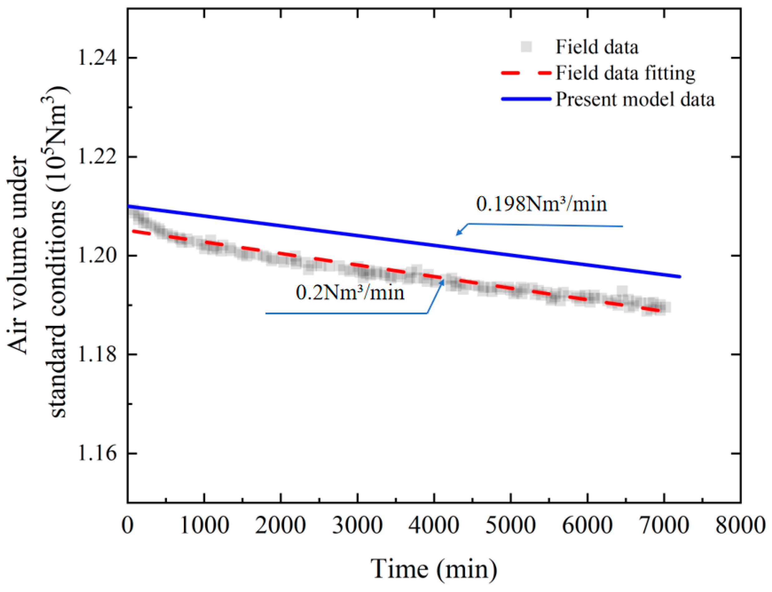
Figure 3 illustrates air volume dynamics during natural leakage, with volumes converted to standard conditions (1 atm, 20 K) using the ideal gas law. The profile exhibits a rapid initial volume decline followed by progressive stabilization. Hori et al. [33] derived a leakage rate of 0.2 Nm3/min through experimental data regression. Numerical simulations employing steady-state permeation equations yielded a leakage rate of 0.198 Nm3/min, with a relative error of only 1%, indicating that the model can accurately capture gas leakage behavior in practical scenarios.

4. Results and Discussion

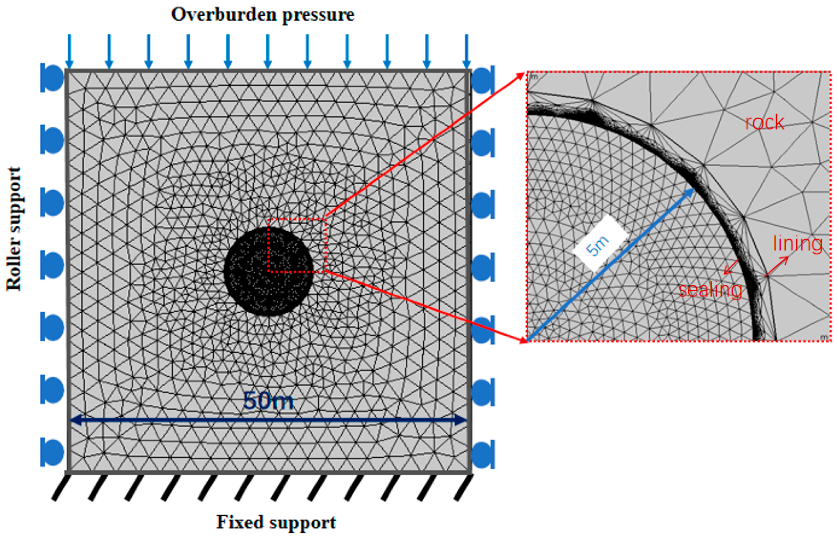
The thermo-hydro-mechanical (THM) coupled numerical model was solved using COMSOL Multiphysics 6.2 software. A two-dimensional model was established with a computational domain of 50   m × 50   m , featuring a cavern radius of 5   m , a sealing layer thickness of 0.01   m , and a lining layer thickness of 0.5   m . The operational cycle was set to 24 h—gas injection during 0–8 h, storage during 8–12 h, gas production during 12–16 h, and storage during 16–24 h. For stress field analysis, boundary conditions were applied as follows: The top boundary received a surface load representing overburden pressure, the left and right boundaries were assigned roller supports, and the bottom boundary was fixed. In thermal analysis, all external boundaries were defined as adiabatic. The initial temperature within the cavern was 273.15   K , with gas injection at 20   k g / s and initial pressure at 4.5   M P a . The initial temperatures of the sealing layer, lining, and surrounding rock matched the cavern temperature. It is assumed that the materials are isotropic, and the sealing layer, lining layer, and surrounding rock all follow the linear elastic constitutive relation without plastic deformation. In addition, the aging and degradation effects of materials during the long-term operation of the storage facility are temporarily neglected. During the computational process, the temperature and pressure within the cavern are solved by the Ordinary Differential Equation (ODE) Module in COMSOL for Equations (1)–(5), the temperature evolution of the sealing layer is determined by the Heat Transfer in Solids Module for Equation (8), and the mechanical response of the sealing layer is resolved through the Solid Mechanics Module for Equations (14)–(17). During the model construction process, to balance computational simplicity and solution efficiency, a non-uniform meshing strategy was adopted—for key regions such as the storage interior, sealing layer, and lining layer, a relatively fine mesh was used to ensure calculation accuracy; for non-key regions like the surrounding rock mass, a relatively coarse mesh was employed to reduce computational costs. Ultimately, a total of 37,980 elements were generated within the entire computational domain. The calculation parameters were set as follows: the time step was set to 1000 s, and the tolerance was taken as 0.001; a fully coupled solver was selected to accurately capture the strong coupling effects between various physical fields and ensure the reliability of the calculation results. The numerical model geometry and boundary conditions are illustrated in Figure 4. The hydrogen permeability coefficient of stainless steel is 4.812 × 10⁻²²  m o l · m 1 · s 1 · P a 0.5 [35], and the remaining calculation parameters are listed in Table 5 [16,18,32].

4.1. Sealing Performance and Mechanical Characteristics of Lined Cavern Materials

4.1.1. Temperature and Pressure Evolution Within the Cavern

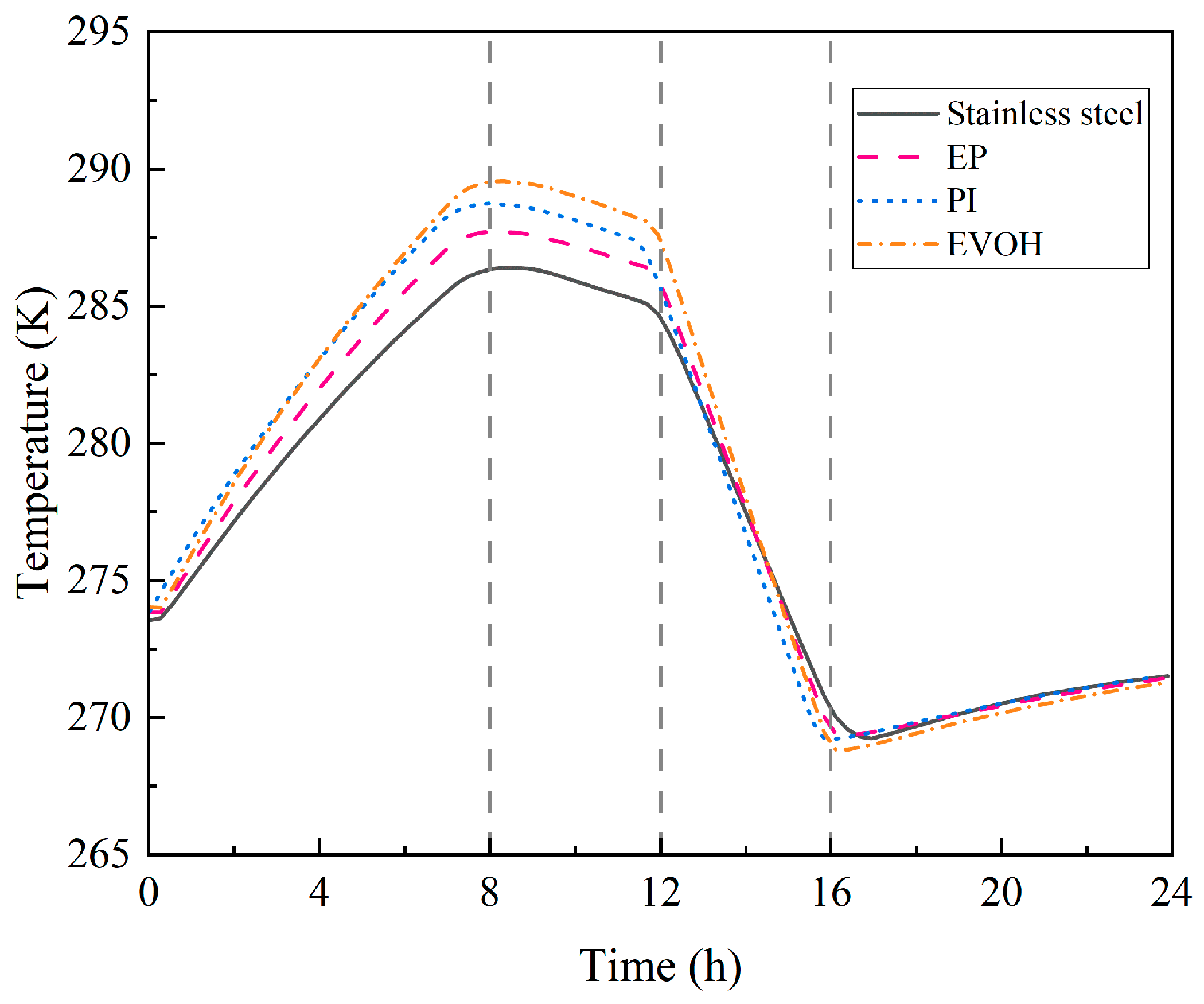
Figure 5 and Figure 6 illustrate the temperature evolution of gas within the cavern and the sealing layer for stainless steel, EP, EVOH, and PI sealing materials, respectively. During the gas injection phase (0–8 h), the temperature variation range of the gas inside the cavern corresponding to the four sealing materials exhibits a decreasing trend in the order of EVOH > PI > EP > stainless steel, with their maximum temperatures reaching 294.98 K, 294.37 K, 293.66 K, and 289.87 K, respectively. From the data, we see that the maximum temperature differences among the three polymer materials (EVOH, PI, and EP) are relatively small, with the largest difference being only 1.32 K; in contrast, the maximum gas temperature in the cavern between stainless steel and EVOH differs significantly by 5.11 K. This temperature variation characteristic shows a significantly negative correlation with the thermal conductivities of the four materials (0.15 W·m−1·k−1, 0.2 W·m−1·k−1, 0.3 W·m−1·k−1, and 20 W·m−1·k−1). Specifically, the thermal conductivity of stainless steel is much higher than that of the three polymer materials (approximately 67 to 133 times), and its excellent thermal conductivity enables it to quickly transfer the heat generated during the gas injection process to the surrounding rock, accelerating heat dissipation. Consequently, the temperature inside the storage cavern is significantly lower than that in scenarios using polymer materials. Mechanistic analysis reveals that sealing materials with low thermal conductivity markedly inhibit heat transfer from the cavern to the surrounding rock. Reduced heat dissipation allows the cavern gas to maintain elevated temperatures, consequently raising the temperature of the adjacent sealing layer. During the second storage phase (16–24 h), both cavern gas and sealing layer temperatures exhibited partial recovery. This phenomenon occurred because the rapid temperature decline following gas extraction in the previous phase caused the cavern temperature to fall below that of the surrounding rock, triggering a heat conduction influx from the rock mass to the cavern.
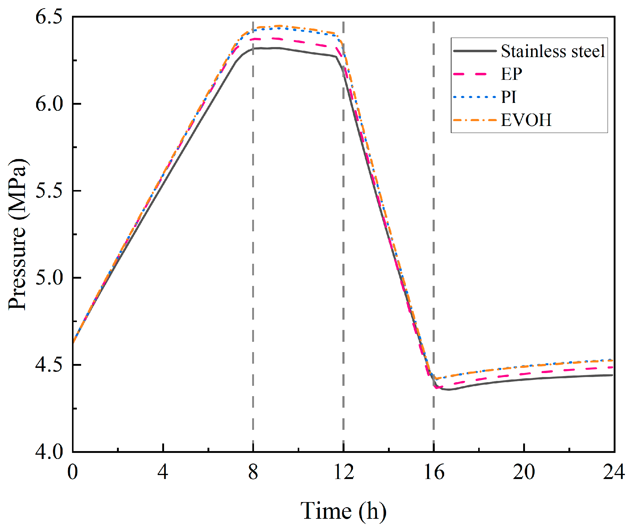
Figure 7 presents operational pressure variations within the cavern, influenced collectively by gas injection/extraction and thermal effects. Changes in gas density during injection/extraction constituted the primary pressure driver, while temperature-induced pressure increases—attributable to the elevated average kinetic energy of hydrogen molecules—played a secondary role. As indicated in Figure 5, minimal temperature differences across sealing materials resulted in negligible pressure variations.

4.1.2. Hydrogen Leakage Dynamics in Cavern

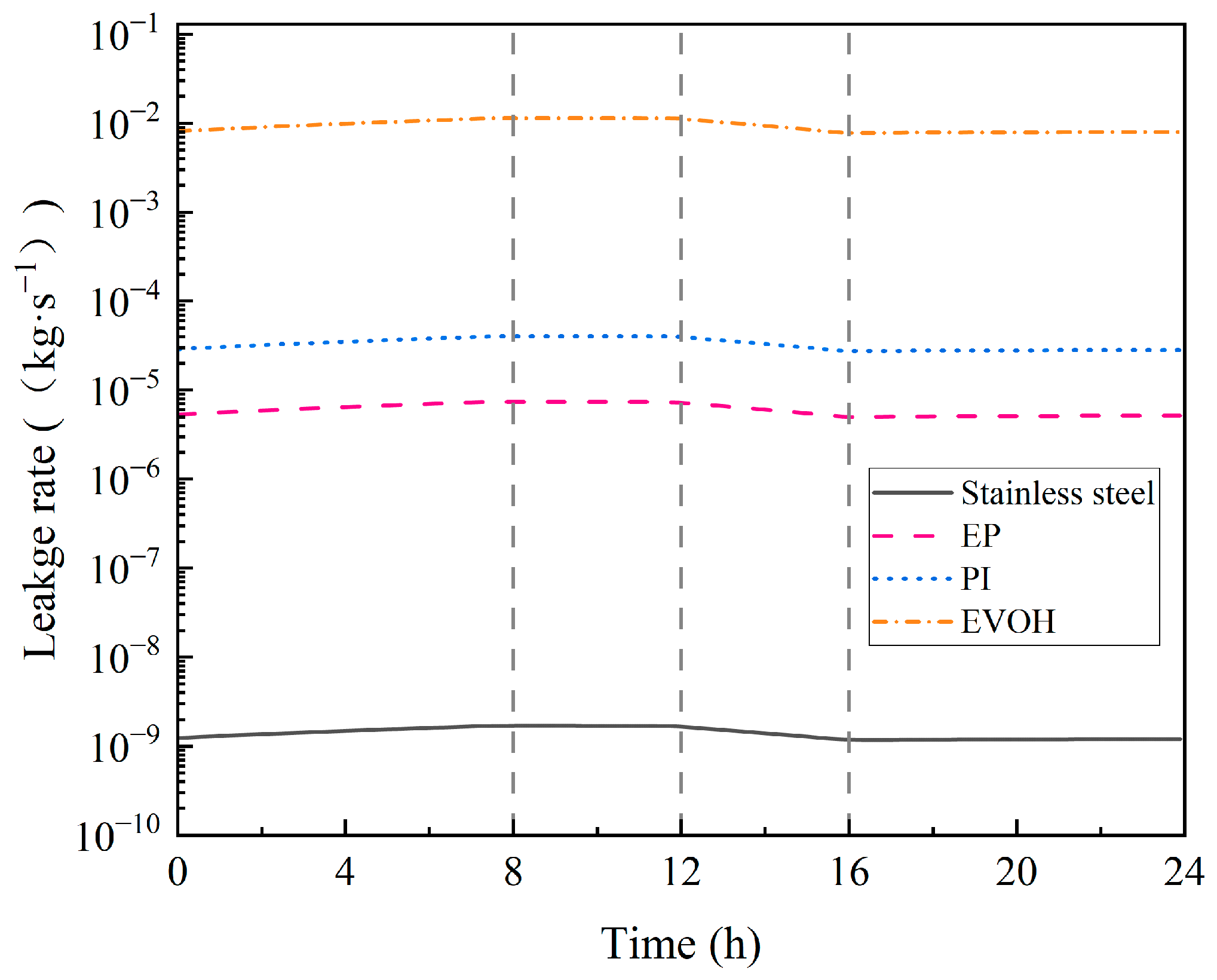
Figure 8 presents the simulation results of the cavern leakage rate under the action of different sealing layer materials. According to the permeability equation of polymer materials, when the operating conditions and geometric parameters are consistent, the hydrogen permeability of the material dominates the hydrogen leakage amount. As shown in the figure, the leakage rates, in descending order, are stainless steel, epoxy resin, polyimide, and ethylene–vinyl alcohol copolymer, which is completely consistent with the order of their hydrogen permeability. Given the lack of specifications for allowable leakage in underground hydrogen storage, this study refers to the allowable leakage ratio of underground gas storage (less than 1%) [12] and the allowable leakage ratio of hydrogen pipeline transportation (less than 0.25% per day) [39]. Based on the data calculation shown in Figure 8, it can be seen that EVOH, which has the highest leakage rate, has a daily leakage rate of only 0.14%, far below the requirements of the aforementioned specifications. In contrast, the leakage rates of stainless steel, EP, and PI are several orders of magnitude lower than that of EVOH, so they can all be used as sealing layer materials for underground lined cavern compressed hydrogen storage, among which stainless steel and epoxy resin are relatively very good.

4.1.3. Mechanical Characteristics of Sealing Layers

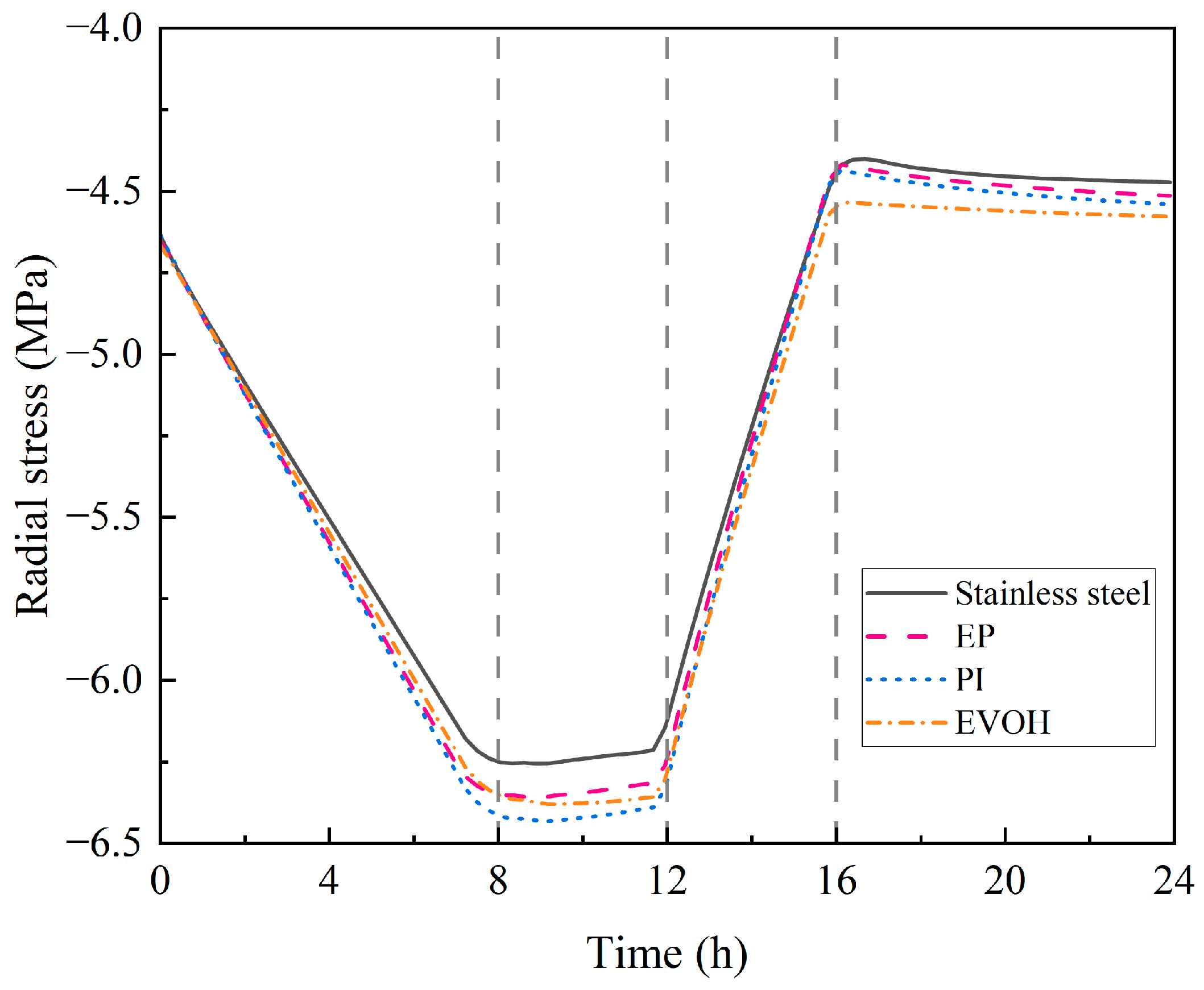
Figure 9 and Figure 10 present the distributions of radial and circumferential stress in the sealing layer of an underground lined cavern for compressed hydrogen storage. The radial stress values remain consistent across all sealing materials, as radial stress is equal to the negative value of cavern pressure. When stainless steel is adopted as the sealing layer material, the maximum pressure inside the cavern can reach 6.3 MPa during the operation of the storage facility. This exerts significant radial and hoop stresses on the steel lining, which constitutes the mechanical driving force for hydrogen embrittlement. In a high-pressure hydrogen environment, hydrogen atoms will diffuse and accumulate in these high-stress regions, then penetrate into the metal interior. This leads to a decrease in the fracture toughness of the steel lining, promotes the initiation and propagation of subcritical cracks, and ultimately induces hydrogen embrittlement. Sun et al. conducted relevant research on the hydrogen embrittlement effect of compressed hydrogen storage facilities in underground lined caverns. The results show that when the stainless steel side is subjected to a pressure of 52 MPa, even after ten years of operation of the storage facility, the degree of crack propagation is still minimal, and the structural deflection is much lower than the elongation at break of the steel, with no obvious damage. However, it should be noted that the core function of the steel lining is to ensure the sealing performance of the storage facility. Even without overall damage after long-term operation, the microcracks generated on its surface may increase the risk of hydrogen leakage. Therefore, in subsequent studies, a composite sealing scheme of “stainless steel lining + surface-sprayed polymer material” can be considered. The synergistic effect of the two not only ensures the sealing performance of the storage facility, but also effectively inhibits the occurrence of hydrogen embrittlement.
Figure 10 demonstrates that the circumferential stress in the stainless steel sealing layer significantly exceeds that of the three polymeric materials (EVOH, EP, and PI). This disparity arises from stainless steel’s rigid nature, characterized by a Young’s modulus substantially higher than those of flexible polymers. Mechanistically, a higher Young’s modulus enhances a material’s resistance to deformation, resulting in minimal strain and limited load redistribution. Consequently, rigid materials sustain elevated stress levels. In contrast, polymeric materials with lower moduli undergo greater deformation, facilitating stress redistribution and reducing internal stresses. Among the polymers, circumferential stress magnitudes follow EVOH > EP > PI, correlating directly with their Poisson’s ratios. Higher Poisson’s ratios restrict deformation capacity, impeding load release and amplifying circumferential stress. Circumferential stress is affected by both the cavern pressure and temperature. Throughout the process, circumferential stress in the sealing layer is predominantly compressive, but tensile stress arises during the initial gas injection stage and the final gas production stage. This occurs because the thermal expansion coefficient of the sealing layer exceeds that of the support structure, and the constraint during expansion and contraction generates tensile stress.
Based on the comparison results of the sealing performance of the four materials, stainless steel and epoxy resin (EP) are recommended as the preferred sealing layer materials. Among them, stainless steel is suitable for scenarios with high pressure and frequent temperature fluctuations, while epoxy resin can be used in medium- and low-pressure storage facilities with requirements for construction convenience and cost.

4.2. Impact of Operating Conditions

Prior studies have systematically characterized the operational behavior of hydrogen storage caverns under typical operating conditions. However, practical engineering requires dynamic parameter adjustments based on geographical constraints, functional requirements, and environmental factors. These adjustments manifest as differentiated configurations of critical parameters, including initial cavern pressure/temperature, hydrogen injection temperature, and mass flow rates. As established in preceding analyses, both stainless steel and epoxy resin exhibit superior sealing performance. However, stainless steel is limited by high costs and susceptibility to hydrogen embrittlement—a potential failure mechanism for sealing layers. Consequently, this study selects epoxy resin as the sealing material and employs a single-variable control methodology to comprehensively evaluate the influence of key operational parameters on sealing integrity, i.e., gas tightness, and mechanical response characteristics.

4.2.1. Initial Pressure in the Cavern

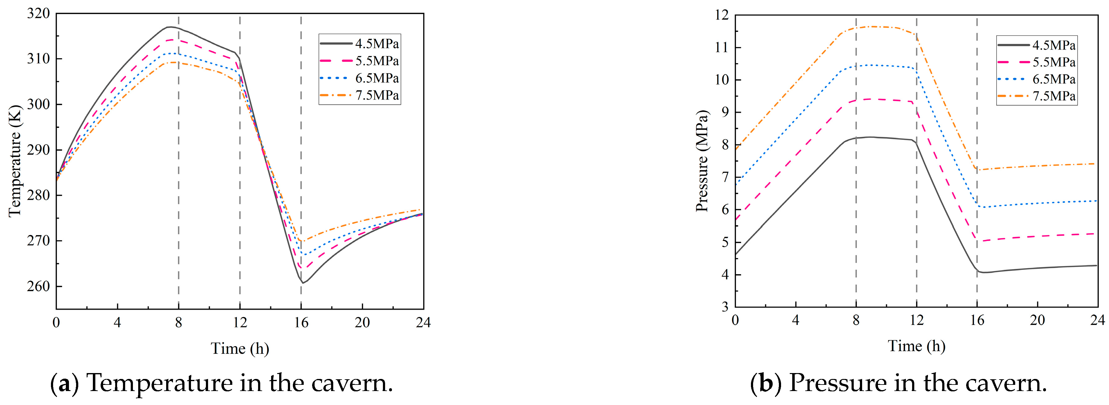
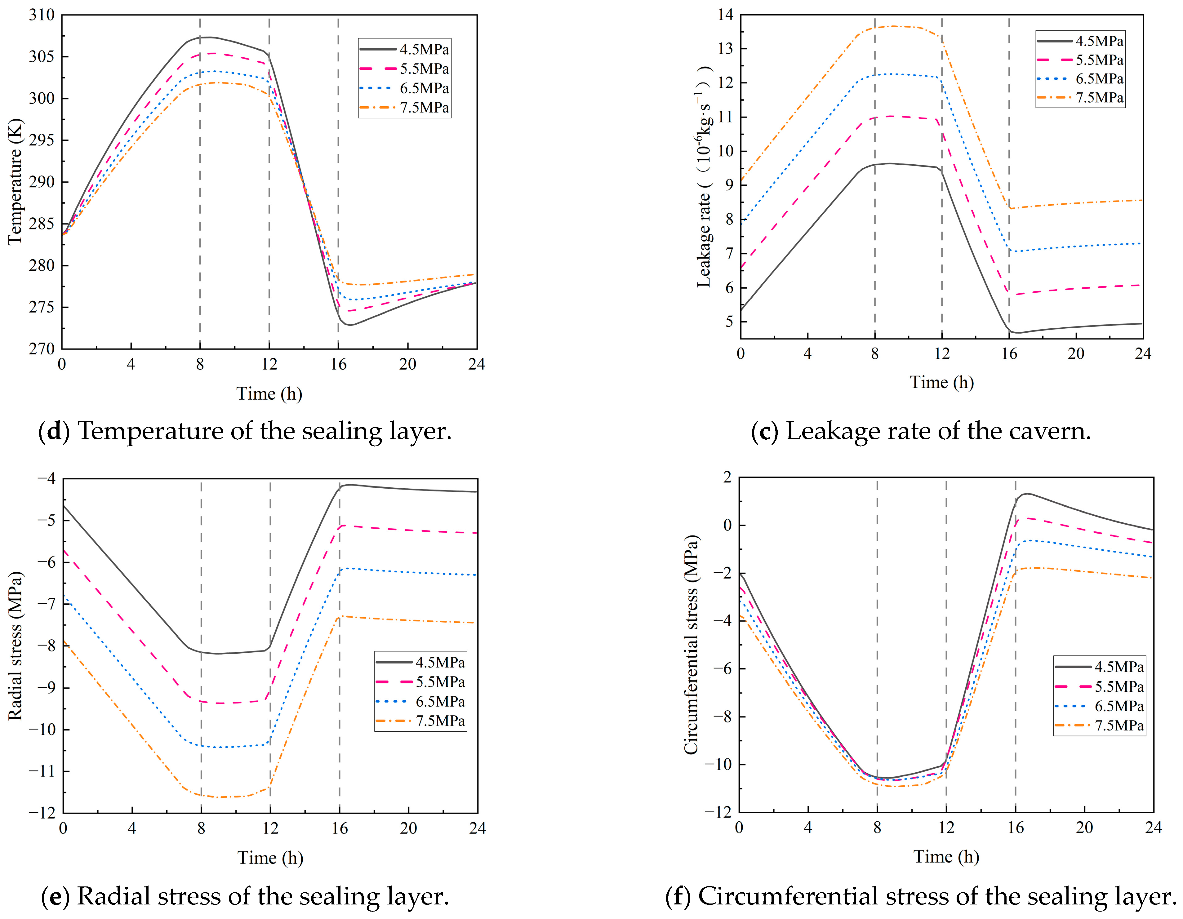
The preset initial pressure of the cavern is used in engineering practice to balance the geological stress of the rock mass and pore hydrostatic pressure. However, this pressure state will affect the thermodynamic behavior of the hydrogen storage cavern, thereby influencing the airtightness and mechanical characteristics of the sealing layer. To quantify the influence law of initial pressure on the integrity of the sealing system, this section establishes numerical simulation conditions with different pressure gradients (4.5 MPa, 5.5 MPa, 6.5 MPa, 7.5 MPa), focusing on analyzing the evolution characteristics of the temperature, stress, and leakage rate of the sealing layer under different initial pressure conditions. It can be observed in Figure 11a that there is a negative correlation between the initial pressure in the hydrogen storage cavern and the maximum operating temperature. This is because the temperature rise during the injection process mainly results from the heat generated by the compression of hydrogen. The higher the initial pressure, the less heat is generated by the compression effect and the lower the temperature, thus improving the safety of the storage cavern. However, this also leads to the insufficient utilization of hydrogen and causes a temperature rise in the cavern after gas extraction. At the same time, it significantly increases the operating pressure in the hydrogen storage cavern and the radial stress of the sealing layer, resulting in an increased risk of damage to the sealing layer and a significant increase in the leakage rate. As shown in Figure 11f, with increasing initial pressure, the circumferential stress of the sealing layer shows a gradual increasing trend, but the change in the maximum value is small, and the stress state is entirely transformed into compressive stress. According to the theory of elastic mechanics, this phenomenon occurs because, in the final stage of extraction, the contribution of temperature load to circumferential stress is relatively limited, while the pressure load in the cavern becomes the dominant factor.

4.2.2. Initial Temperature in the Cavern

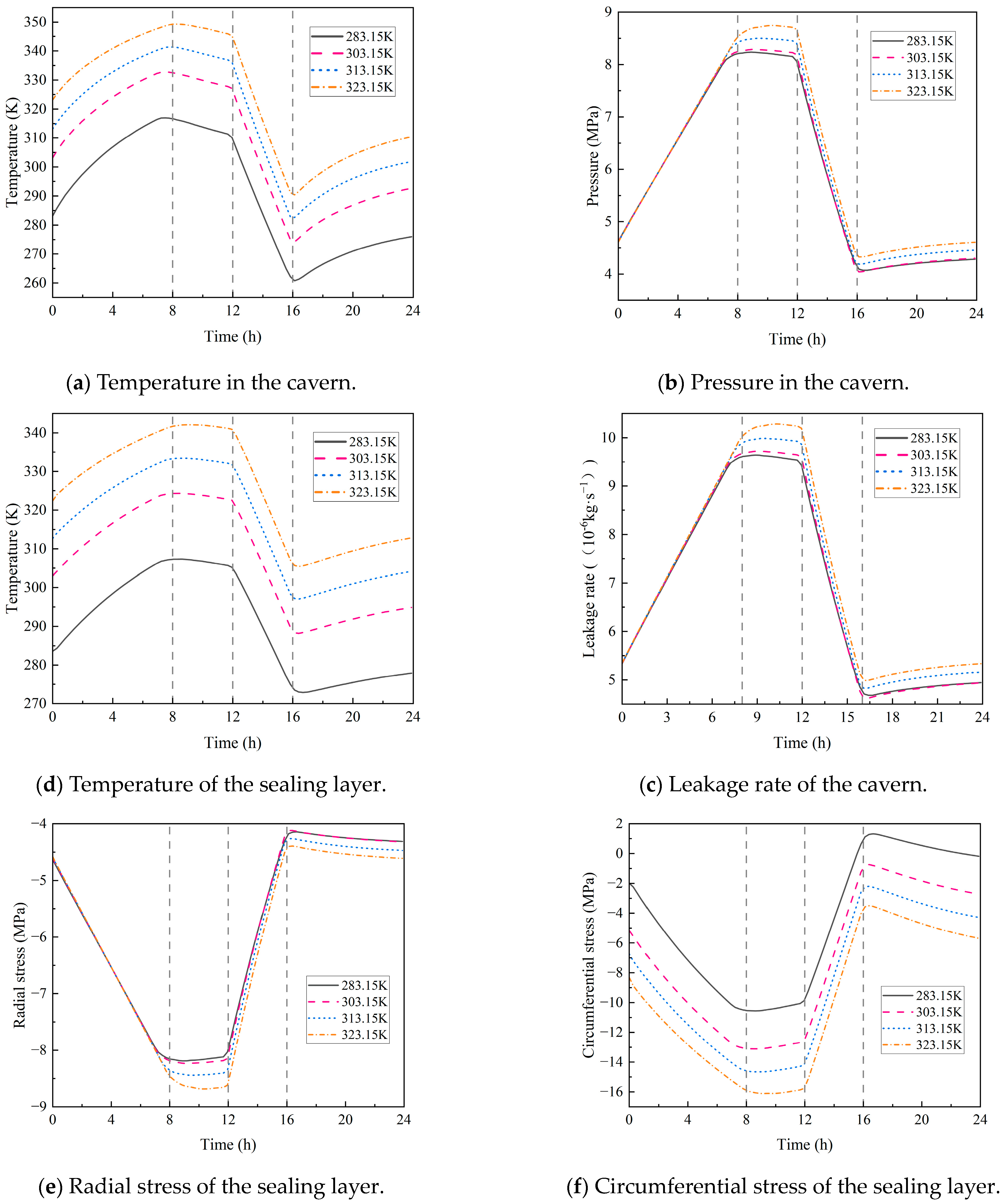
In actual engineering scenarios, the initial temperature of hydrogen storage caverns is affected by both differences in environmental conditions and specific engineering requirements. Changes in this parameter will further affect the temperature rise of hydrogen and the heat conduction behavior among the sealing layer, the lining layer, and the surrounding rock. Therefore, this paper selects four initial temperature conditions (283.15 K, 303.15 K, 313.15 K, 323.15 K) to simulate the operational behavior of hydrogen storage caverns. It can be seen from Figure 12 that with increasing initial temperature, the gas temperature and the temperature of the sealing layer increase synchronously, but the pressure does not change significantly. This phenomenon verifies that the pressure of the hydrogen storage cavern mainly comes from the compression of hydrogen, and the influence of temperature on it is limited. Since the radial stress is the negative value of the pressure, its variation trend is consistent with that of the pressure, with no obvious fluctuation. In addition, the leakage rate is mainly dominated by pressure, so it is also weakly affected by the initial temperature. It is worth noting that with increasing temperature, the circumferential stress of the sealing layer gradually increases. Combined with the analysis in the previous section, it is evident that the circumferential stress is not only affected by pressure factors but also by thermal load, which is an important influencing factor. For every 10 K increase in temperature, the maximum circumferential stress increases by 11%.

4.2.3. Hydrogen Injection Temperature

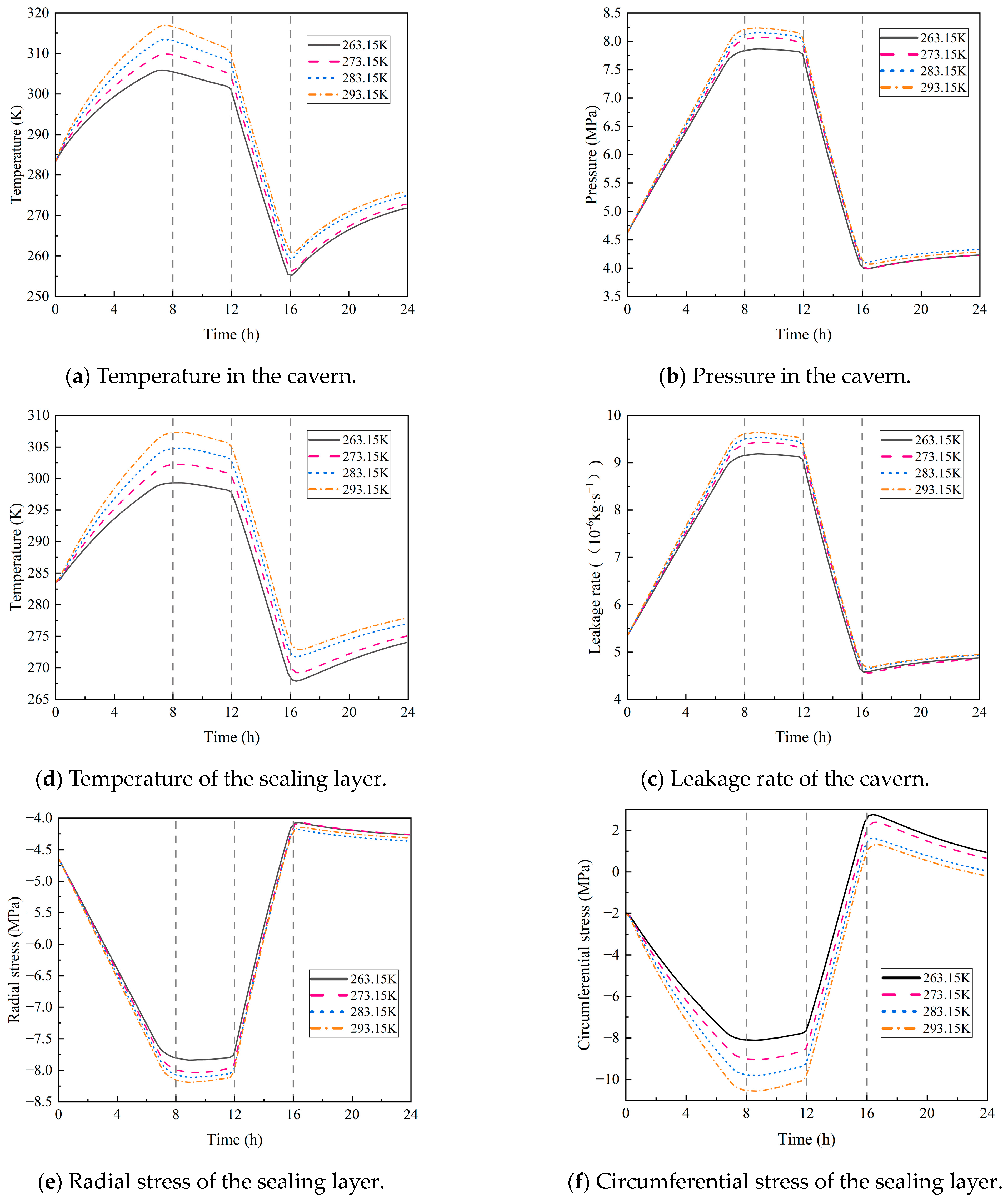
In actual hydrogen injection and production projects, to effectively control the temperature rise during the injection process and improve the safety of hydrogen storage operations, precooling is usually applied to the injected hydrogen. Based on this engineering background, this section selects four hydrogen injection temperature conditions—263.15 K, 273.15 K, 283.15 K, and 293.15 K—sets the ambient temperature at 273.15 K and the initial pressure at 4.5 MPa, and conducts a numerical simulation study on the injection and production process of the hydrogen storage cavern. It can be seen from Figure 13 that during the injection and production process, with increasing gas injection temperature, both the gas temperature in the cavern and the temperature of the sealing layer show a certain rising trend, but the pressure does not change significantly, which in turn leads to small changes in the radial stress and leakage rate. It is worth noting that the circumferential stress shows an obvious response characteristic with increasing injection temperature, which is significantly affected by the thermal expansion caused by the temperature gradient. For every 10 K increase in injection temperature, the circumferential stress increases by 11%, which further verifies that the temperature load cannot be ignored in the mechanical response of the sealing structure of the hydrogen storage cavern.

4.2.4. Hydrogen Injection and Production Rate

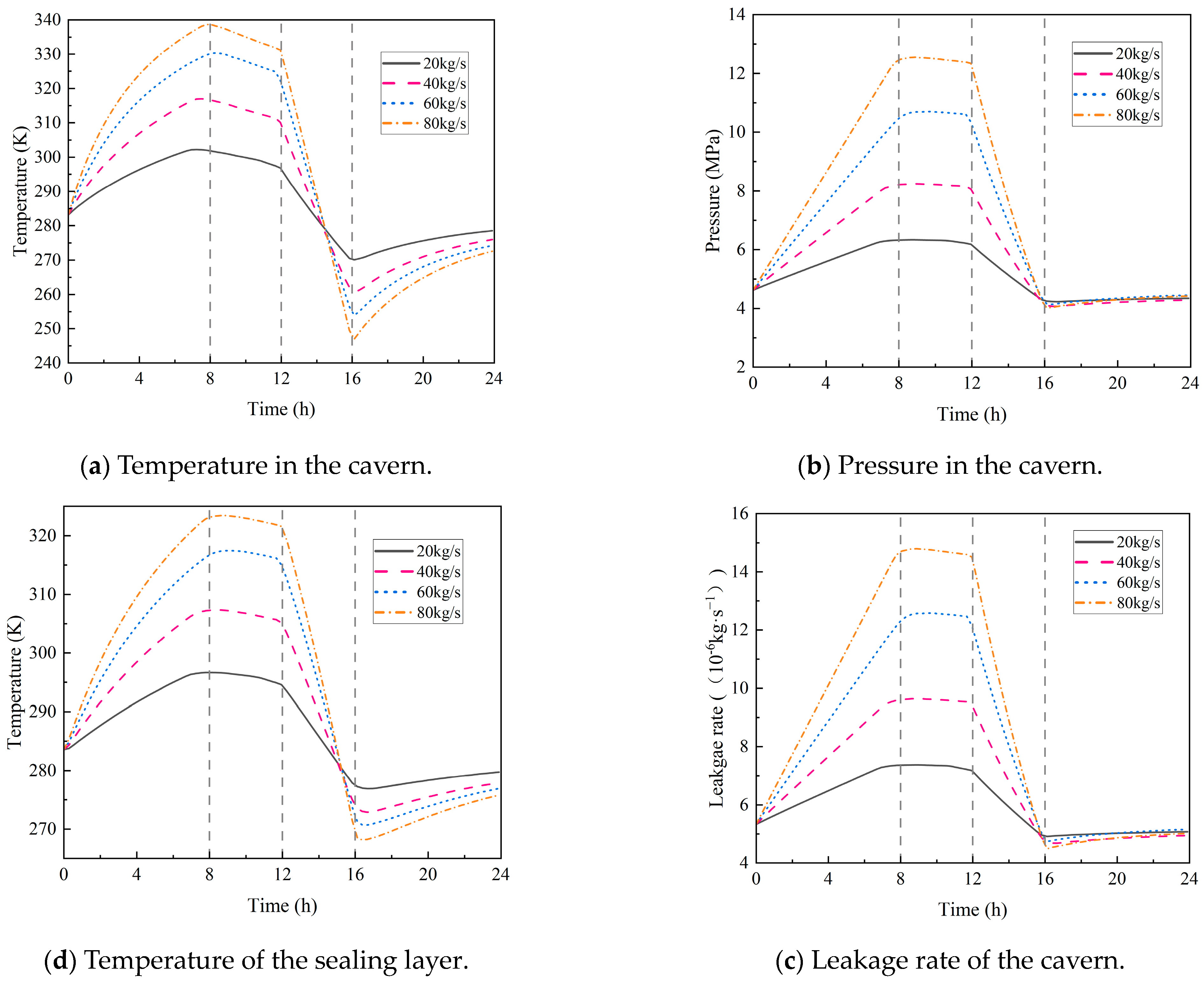
In practical applications of hydrogen storage engineering, the dynamic adjustment of hydrogen injection and production rates is usually required to balance supply–demand relationships and optimize resource utilization efficiency. Although the regulation of injection and production rates can meet diversified energy demands, such changes will significantly affect the temperature and pressure evolution in hydrogen storage caverns, thereby potentially impacting the airtightness and structural stability of the sealing layer. Based on this, this section sets four injection and production rates (20 kg/s, 40 kg/s, 60 kg/s, 80 kg/s) to conduct numerical simulation studies and evaluate their effects on the thermodynamic characteristics of hydrogen storage caverns. As shown in Figure 14, the increase in injection and production rates has a significant impact on the temperature–pressure field in the hydrogen storage cavern and the mechanical response of the sealing layer. When the injection rate increases in increments of 20 kg/s, the maximum temperatures of the gas and the sealing layer show a regular upward trend, with the maximum temperature increasing by approximately 8% for each rate increment.
However, as the injection and production rates increase, the temperature inside the cavern drops rapidly during the gas production phase, with the minimum temperature reaching 246.97 K, putting the interior of the storage cavern in a low-temperature state. The cause of this phenomenon is as follows; when the hydrogen production process is fast, the time for heat transfer from the surrounding area of the cavern to the hydrogen is short, and the heat input is low. Therefore, the entire process can be approximated as adiabatic expansion—hydrogen completes expansion only through changes in its own internal energy. Since internal energy is directly related to temperature, the consumption of internal energy leads to a significant decrease in hydrogen temperature, even dropping to 246.97 K. This low-temperature phenomenon is a critical safety concern for the sealing layer. First, when the temperature drops sharply from a high level to a low temperature, the sealing layer undergoes drastic thermal shrinkage, generating large internal stresses within the material. These stresses easily exceed the tensile strength limit of the sealing layer, inducing microcracks or even macroscale damage, thereby significantly increasing the hydrogen leakage rate. Second, low temperatures trigger material embrittlement, particularly for polymer-based sealing materials (e.g., EVOH, PI, EP), whose toughness and impact resistance are significantly reduced, making the sealing layer more susceptible to damage under cyclic temperature–pressure loading. Third, the abrupt thermal cycle (the rapid switch from high temperature during the gas injection phase to low temperature during the gas production phase) weakens the interfacial adhesion between the sealing layer and the surrounding lining/rock mass, creating additional leakage paths and further compromising the overall airtightness of the storage system.
In addition, the increase in injection and production rates also leads to an approximate 12% increase in the maximum pressure in the cavern, which directly causes a synchronous increase in the leakage rate. Meanwhile, the radial stress also increases significantly with the increase in injection and production rates. As shown in Figure 14f, the circumferential stress also rises, but its increase amplitude is smaller compared with that during the phase of increasing circumferential compressive stress. This is because during the gas production process, the sealing layer rapidly transitions from a compressed state to a tensile state; however, due to the relatively short gas production process and a certain buffer in pressure drop, the circumferential tensile stress increases but with a smaller amplitude than that of the compressive stress increase.
Based on the influence law of operating parameters on sealing performance, we suggest that the initial temperature should be controlled at 273.15–283.15 K, the initial pressure should not exceed 5.5 MPa, the temperature difference between hydrogen injection temperature and initial temperature should be controlled within 10 K, and the injection–production rate is recommended to be stabilized at 20–40 kg/s to balance storage efficiency and sealing durability.

5. Conclusions

To accurately analyze the sealing performance of underground lined caverns for hydrogen storage, this study establishes a multiphysical coupling model that accounts for the real gas properties of hydrogen and the effect of temperature on permeability (integrating Fick’s first law, the steady-state gas permeation equation for the sealing layer, and the Arrhenius equation). The reliability of the established model is validated against analytical solutions and operational data from a real underground compressed air storage facility. The study systematically investigates the performance of sealing materials and the influence of key operating parameters on the hydrogen leakage behavior. The main conclusions are as follows:
(1)
During the injection phase (0–8 h), continuous hydrogen injection synchronously raises cavern pressure and temperature, and the pressure drives a slow upward leakage rate. In the first storage phase (8–12 h), pressure and temperature stabilize, and the leakage rate peaks with small fluctuations. In the production phase (12–16 h), hydrogen discharge lowers cavern pressure and temperature significantly, reducing the leakage rate slowly. Although the sealing layer may develop local tensile stress (due to the thermal expansion coefficient difference with the support structure), leakage stays controlled. In the second storage phase (16–24 h), cavern temperature and pressure rise slowly with tiny variations, and the leakage rate remains stable;
(2)
Stainless steel has the best sealing performance, but it has drawbacks such as its high cost and susceptibility to hydrogen embrittlement (which may cause the deterioration of mechanical properties during long-term service). Epoxy resin (EP) offers excellent sealing, temperature resistance, cost-effectiveness, and no hydrogen embrittlement, making it ideal as a stainless steel alternative under medium–low-pressure and cost-sensitive conditions. Polyimide (PI) excels in anti-aging, high-temperature resistance, and sealing reliability, although it is costly. Ethylene–vinyl alcohol copolymer (EVOH) has poor hydrogen barrier performance and sensitivity to temperature/humidity, making it suitable only for stable environments. For anti-aging, PI is best, followed by EP, with EVOH being relatively weaker;
(3)
Both the initial temperature of the storage and the hydrogen injection temperature have a significant impact on the circumferential stress of the sealing layer. For every 10 K increase in the initial temperature, the circumferential stress rises by 11%. For every 10 K increase in the injection temperature, the circumferential stress increases by 10%, with little impact on the leakage rate. In addition, the initial pressure of the storage and the hydrogen injection rate exert a considerable influence on airtightness. Each 1 MPa increase in the initial pressure causes the leakage rate to rise by 11%, and every 20 kg/s increase in the injection rate leads to a 12% increase in the leakage rate.
Notably, this study does not consider the long-term degradation of sealing layer materials caused by hydrogen’s physicochemical properties. Future research should introduce material aging models and incorporate long-term service data to build a multi-field coupled degradation model. Additionally, hydrogen embrittlement’s mechanism is complex and lacks a universal explanation, and subsequent work will combine experiments and numerical simulations to investigate its mechanism and establish a theory suitable for compressed hydrogen storage in underground lined caverns.

Author Contributions

Conceptualization, S.C., Y.L. and Y.C.; methodology, S.C., Y.L., Y.C. and J.Z.; validation, Y.C. and J.Z.; formal analysis, S.C., Y.L. and Y.C.; investigation, S.C., Y.L., Y.C. and J.Z.; writing—original draft preparation, Y.C. and J.Z.; writing—review and editing, S.C., Y.L. and Y.C. All authors have read and agreed to the published version of the manuscript.

Funding

This research received funding from the National Natural Science Foundation of China (Grant No. U23A6018), Science and Technology Program of Hebei (Grant No. E2022202041, 2022HBQZYCXY004, 242Q9920Z).

Data Availability Statement

The original contributions presented in this study are included in this article. Further inquiries can be directed to the corresponding authors.

Conflicts of Interest

Authors Shaodong Cui and Yin Li was employed by the China Petroleum Pipeline Engineering Co., Ltd. The remaining authors declare that the research was conducted in the absence of any commercial or financial relationships that could be construed as a potential conflict of interest.

Nomenclature

V Cavern volume J Diffusive flux
ρ Density of hydrogen within the cavern D Diffusion coefficient
F i Dimensionless periodic function for gas injection c Concentration gradient
F e Dimensionless periodic function for gas production c Hydrogen concentration
m ˙ c Gas mass flow rate of the compressor L Thickness of the sealing layer
m 1 t Hydrogen mass leakage rate from the cavern S Solubility coefficient
c v Constant-volume specific heat capacity of the gas p 1 Hydrogen partial pressures at the inner boundaries of the sealing layer
T Temperature of the gas within the cavern p 2 Hydrogen partial pressures at the outer boundaries of the sealing layer
h i Enthalpy of the injected gas p o u t Gas pressure on the outer side of the sealing layer
h the enthalpy of the gas k Permeability coefficient of stainless steel
Z Gas compressibility factor M Molar mass of hydrogen
R Gas constant P Permeability of the polymeric material,
u Specific internal energy of the gas ρ s Density of air at 273.15   K under standard atmospheric pressure
Q ˙ Heat transfer rate at the cavern wall surface E p Activation energy
C D Ratio of injected gas mass flow rate to produced gas mass flow rate ρ j Density of the j -th layer medium
c p Constant-pressure specific heat capacity of the gas c p j Constant-pressure specific heat capacity of the j -th layer medium
T i Temperature of the injected gas k j Thermal conductivity of the j -th layer medium
Z T 0 Partial derivative of the gas compressibility factor with respect to temperature at the initial state T j Temperature of the j -th layer medium
p Pressure within the cavern σ Cauchy stress tensor
p c Gas pressure at the critical state F v Body force vector per unit volume
T c Gas temperature at the critical state C Fourth-order elasticity tensor
h c Convective heat transfer coefficient:Double-dot product (tensor contraction)
A c Cavern surface area ε Infinitesimal strain tensor
T r 0 , t Temperature at the cavern wall surface α Coefficient of thermal expansion
r 0 Radius of the cavern

References

  1. Shu, K.Y.; Guan, B.; Zhuang, Z.Q.; Chen, J.; Zhu, L.; Ma, Z.; Hu, X.; Zhu, C.; Zhao, S.; Dang, H.; et al. Reshaping the energy landscape: Explorations and strategic perspectives on hydrogen energy preparation, efficient storage, safe transportation and wide applications. Int. J. Hydrogen Energy 2025, 97, 160–213. [Google Scholar] [CrossRef]
  2. Mwakipunda, G.C.; Kouassi, A.K.F.; Ayimadu, E.T.; Komba, N.A.; Nadege, M.N.; Mgimba, M.M.; Ngata, M.R.; Yu, L. Underground hydrogen storage in geological formations: A review. J. Rock Mech. Geotech. Eng. 2025, 17, 6704–6741. [Google Scholar] [CrossRef]
  3. Leng, G.; Yan, W.; Chen, Z.; Li, Z.; Liu, B.; Deng, P.; Zhang, C.; Liu, W.; Qi, H. Technical challenges and opportunities of hydrogen storage: A comprehensive review on different types of underground storage. J. Energy Storage 2025, 114, 115900. [Google Scholar] [CrossRef]
  4. Ho, T.A.; Dang, S.T.; Dasgupta, N.; Choudhary, A.; Rai, C.S.; Wang, Y. Nuclear magnetic resonance and molecular simulation study of H2 and CH4 adsorption onto shale and sandstone for hydrogen geological storage. Int. J. Hydrogen Energy 2024, 51, 158–166. [Google Scholar] [CrossRef]
  5. Muhammed, N.S.; Haq, B.; Al Shehri, D.; Al-Ahmed, A.; Rahman, M.M.; Zaman, E. A review on underground hydrogen storage: Insight into geological sites, influencing factors and future outlook. Energy Rep. 2022, 8, 461–499. [Google Scholar] [CrossRef]
  6. Sari, M.; Sarout, J.; Esteban, L.; Mandal, P.P.; Nguyen, D.; Mallants, D. Hydrogen geo-storage in rock salt formations: Petrophysical characterisation and geomechanical testing of a potential host formation in Western Australia. In Proceedings of the Australian Hydrogen Research Conference, Canberra, Australia, 8–10 February 2023. [Google Scholar]
  7. Michelsen, J.; Hagemann, B.; Ganzer, L.; Hujer, W. Measurement of hydrogen diffusion through caprock samples. In Proceedings of the Sixth International Conference on Fault and Top Seals, Vienna, Austria, 26–28 September 2022; Volume 2022, pp. 1–5. [Google Scholar] [CrossRef]
  8. Muhammed, N.S.; Haq, M.B.; Al Shehri, D.; Al-Ahmed, A.; Rahman, M.M.; Zaman, E.; Iglauer, S. Hydrogen storage in depleted gas reservoirs: A comprehensive review. Fuel 2023, 337, 127032. [Google Scholar] [CrossRef]
  9. Zivar, D.; Kumar, S.; Foroozesh, J. Underground hydrogen storage: A comprehensive review. Int. J. Hydrogen Energy 2021, 46, 23436–23462. [Google Scholar] [CrossRef]
  10. Karellas, S.; Tzouganatos, N. Comparison of the performance of compressed-air and hydrogen energy storage systems: Karpathos island case study. Renew. Sustain. Energy Rev. 2014, 29, 865–882. [Google Scholar] [CrossRef]
  11. Kim, H.M.; Rutqvist, J.; Jeong, J.H.; Choi, B.-H.; Ryu, D.-W.; Song, W.-K. Characterizing excavation damaged zone and stability of pressurized lined rock caverns for underground compressed air energy storage. Rock Mech. Rock Eng. 2013, 46, 1113–1124. [Google Scholar] [CrossRef]
  12. Allen, R.D.; Doherty, T.J.; Kannberg, L.D. Summary of Selected Compressed Air Energy Storage Studies; Pacific Northwest Laboratory: Richland, WA, USA, 1985; PNL-5091. [Google Scholar]
  13. Wu, D.; Wang, J.G.; Hu, B.; Yang, S.-Q. A coupled thermo-hydro-mechanical model for evaluating air leakage from an unlined compressed air energy storage cavern. Renew. Energy 2020, 146, 907–920. [Google Scholar] [CrossRef]
  14. Rutqvist, J.; Kim, H.M.; Ryu, D.W.; Synn, J.-H.; Song, W.-K. Modeling of coupled thermodynamic and geomechanical performance of underground compressed air energy storage in lined rock caverns. Int. J. Rock Mech. Min. Sci. 2012, 52, 71–81. [Google Scholar] [CrossRef]
  15. Qin, S.K.; Xia, C.C.; Zhou, S.W. Air tightness of compressed air storage energy caverns with polymer sealing layer subjected to various air pressures. J. Rock Mech. Geotech. Eng. 2023, 15, 2105–2116. [Google Scholar] [CrossRef]
  16. Zhou, Y.; Xia, C.C.; Zhou, S.W.; Zhang, P. Air tightness and mechanical properties of polymer sealing layers in compressed air energy storage lined caverns. Chin. J. Rock Mech. Eng. 2018, 37, 2685–2696. [Google Scholar]
  17. Ahmed, I.H.; Alakoul, K.A.; Al-Manea, A.; Wetaify, A.R.H.; Saleh, K.; Al-Rbaihat, R.; Alahmer, A. An overview of hydrogen production techniques: Challenges and limiting factors in achieving wide-scale productivity. AIP Conf. Proc. 2024, 3051, 050003. [Google Scholar] [CrossRef]
  18. Hu, B.W.; Yu, Y.L.; Mi, Z.X.; Xu, F.; Li, S.; Li, W.; Wei, C.; Zhang, T. Comparative analysis of thermodynamic and mechanical responses between underground hydrogen storage and compressed air energy storage in lined rock caverns. Int. J. Min. Sci. Technol. 2024, 34, 531–543. [Google Scholar] [CrossRef]
  19. Bachand, A.; Doyon, B.; Raymond, J. Thermo-physical numerical model for hydrogen storage in underground tanks and caverns. Int. J. Hydrogen Energy 2024, 66, 66–80. [Google Scholar] [CrossRef]
  20. Wei, L.Y.; Zhen, M.X.; Hu, B.W.; Li, S.; Liu, R.; Ye, J. Three-dimensional thermo-hydro-mechanical coupling model of lined rock cavern hydrogen storage and stability analysis of cavern group operation. J. China Univ. Min. Technol. 2024, 53, 1099–1116. [Google Scholar] [CrossRef]
  21. Liu, H.T.; Li, P.; Wang, T.; Tang, X.; Wang, Z.; Liu, L.; Luo, J.; Tang, J. Thermodynamic performance of hydrogen in lined rock caverns for large-scale underground storage: Short-term and long-term analyses. J. Energy Storage 2025, 117, 116149. [Google Scholar] [CrossRef]
  22. Maes, C.; Luyten, W.; Herremans, G.; Peeters, R.; Carleer, R.; Buntinx, M. Recent Updates on the Barrier Properties of Ethylene Vinyl Alcohol Copolymer (EVOH): A Review. Polym. Rev. 2018, 58, 209–246. [Google Scholar] [CrossRef]
  23. Zhang, Q.; Chen, L.; Li, X.; Hou, B.; Wu, X.; Gui, X.; Cao, D.; Liu, J.; Li, J.; Duan, J.; et al. Robust, high-temperature-eesistant polyimide separators with vertically aligned uniform nanochannels for high-performance lithium-ion batteries. ACS Nano 2024, 18, 32162–32174. [Google Scholar] [CrossRef]
  24. Sun, Z.; Wu, F.; Fager, A.; Crouse, B. Numerical analysis of hydrogen storage in lined rock cavern under high pressure and its implications to hydrogen embrittlement. Int. J. Hydrogen Energy 2024, 80, 1021–1029. [Google Scholar] [CrossRef]
  25. Gajda, D. Epoxy resin for sealing the underground hydrogen storage reservoirs. In Proceedings of the 5th International Conference on Energy Harvesting, Storage and Transfer (EHST’21), Virtual Conference, 21–23 May 2021. [Google Scholar] [CrossRef]
  26. Kushnir, R.; Dayan, A.; Ullmann, A. Temperature and pressure variations within compressed air energy storage caverns. Int. J. Heat Mass Transf. 2021, 55, 5616–5630. [Google Scholar] [CrossRef]
  27. Kushnir, R.; Ullmann, A.; Dayan, A. Thermodynamic models for the temperature and pressure variations within adiabatic caverns of compressed air energy storage plants. J. Energy Resour. Technol. 2012, 132, 021901. [Google Scholar] [CrossRef]
  28. Díaz, A.; Alegre, J.M.; Cuesta, I.I. A review on diffusion modelling in hydrogen related failures of metals. Eng. Fail. Anal. 2016, 66, 577–595. [Google Scholar] [CrossRef]
  29. Liu, M. Corrosion and mechanical behavior of metal materials. Materials 2023, 16, 973. [Google Scholar] [CrossRef] [PubMed]
  30. Flaconnèche, B.; Martin, J.; Klopffer, M.H. Transport properties of gases in polymers: Experimental methods. Oil Gas Sci. Technol. 2001, 56, 245–259. [Google Scholar] [CrossRef]
  31. Chen, W.H.; Lin, C.N.; Chi, Y.H.; Lin, Y.L. Permeation characteristics of hydrogen through palladium membranes in binary and ternary gas mixtures. Int. J. Energy Res. 2017, 41, 1579–1595. [Google Scholar] [CrossRef]
  32. Xia, C.C.; Zhou, Y.; Zhou, S.W.; Wang, X.J.; Mei, S.H.; Zhou, S.W. Key Technologies of Underground Rock-Lined Caverns for Compressed Air Energy Storage; Tongji University Press: Shanghai, China, 2023; pp. 45–56. [Google Scholar]
  33. Hori, M.; Goda, Y.; Onishi, H. Mechanical behaviour of surrounding rock mass and new lining structure of air-tight pressure cavern. In Proceedings of the ISRM Congress, Sandton, South Africa, 8–12 September 2003. ISRM-10CONGRESS-088. [Google Scholar]
  34. Zhou, Y.; Xia, C.C.; Zhao, H.B.; Wang, X.J.; Mei, S.H.; Zhou, S.W. A method for estimating air leakage through inner seals and mechanical responses of the surrounding rock of lined rock caverns for compressed air energy storage. Chin. J. Rock Mech. Eng. 2017, 36, 297–309. [Google Scholar] [CrossRef]
  35. Li, S.; He, D.; Liu, X.P.; Zhang, C.; Wang, S.-M.; Yu, Q.-H.; Qiu, H.-C.; Jiang, L.-J. Hydrogen permeation properties of alumina coating on 316L stainless steel. J. Inorg. Mater. 2013, 28, 775–779. [Google Scholar]
  36. Gajda, D.; Lutyński, M. Hydrogen permeability of epoxy composites as liners in lined rock caverns—Experimental study. Appl. Sci. 2021, 11, 3885. [Google Scholar] [CrossRef]
  37. Zhang, X.; Zhai, L.; Li, H.; Qi, G.; Gao, X.; Yang, W. Molecular simulation study on the hydrogen permeation behavior and mechanism of common polymers. Polymers 2024, 16, 953. [Google Scholar] [CrossRef] [PubMed]
  38. Kurata, K.; Mano, H.; Sakurai, M.; Notomi, M. Evaluation of hydrogen permeability of polymer membranes. J. Soc. Mater. Sci. Jpn. 2022, 71, 903–909. [Google Scholar] [CrossRef]
  39. QX/T 357-2016; Technical Specification for Meteorological Hydrogen Operation Safety. Chinese Meteorological Administration: Beijing, China, 2016.
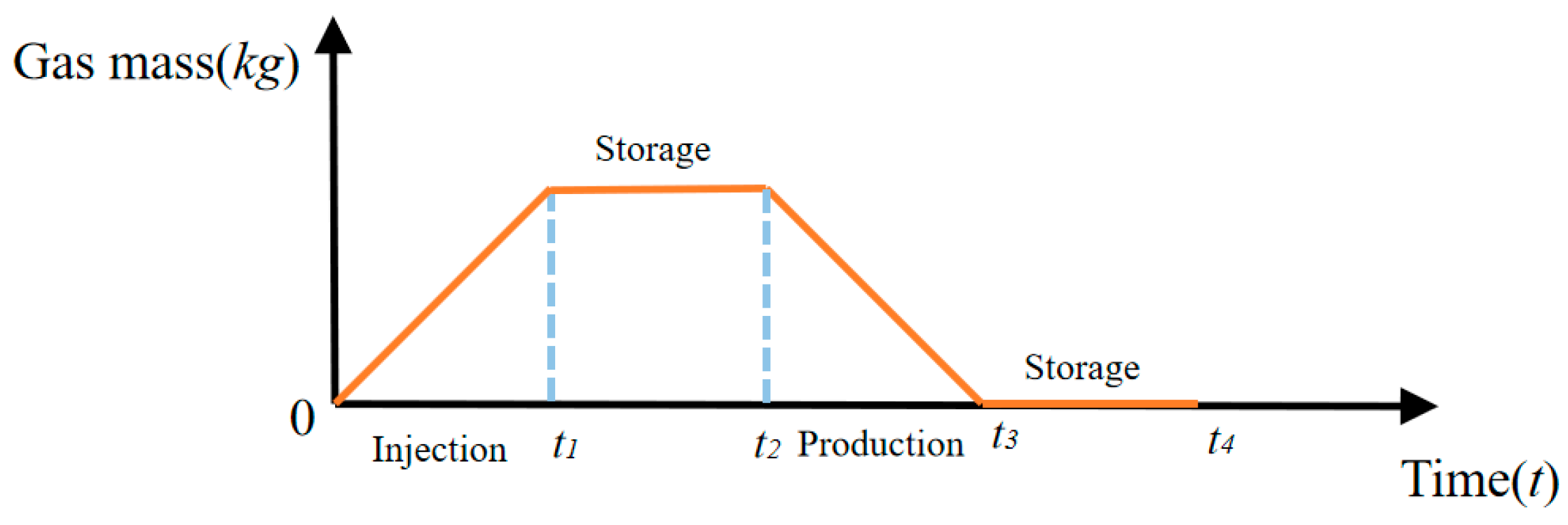
Figure 1. The single-cycle operation process of the storage.
Processes 13 03716 g001
Figure 2. Single-cycle comparison of storage temperature, sealing layer temperature, and storage pressure: (a) storage temperature, (b) sealing layer temperature, (c) storage pressure [32].
Processes 13 03716 g002
Figure 3. Comparison of air volume changes in the Hokkaido experimental cavern, Japan.
Processes 13 03716 g003
Figure 4. Mesh generation and boundary conditions.
Processes 13 03716 g004
Figure 5. The evolution of cavern hydrogen temperature (different sealing layer materials).
Processes 13 03716 g005
Figure 6. The evolution of sealing layer temperature (different sealing layer materials).
Processes 13 03716 g006
Figure 7. The evolution of cavern pressure (different sealing layer materials).
Processes 13 03716 g007
Figure 8. The evolution of the cavern hydrogen leakage rate (different sealing layer materials).
Processes 13 03716 g008
Figure 9. The evolution of sealing layer radial stress (different sealing layer materials).
Processes 13 03716 g009
Figure 10. The evolution of sealing layer circumferential stress (different sealing layer materials).
Processes 13 03716 g010
Figure 11. Influence of initial pressures on cavern operation.
Processes 13 03716 g011aProcesses 13 03716 g011b
Figure 12. Influence of initial temperatures on cavern operation.
Processes 13 03716 g012
Figure 13. Influence of injection temperatures on cavern operation.
Processes 13 03716 g013
Figure 14. Influence of injection–production rates on storage operation.
Processes 13 03716 g014aProcesses 13 03716 g014b
Table 1. Operation parameters of the analytical solution.
ParametersDefinitionsValuesUnits
V Cavern volume3 × 105 m 3
r Cavern radius8 m
d 1 Sealing layer thickness0.1 m
d 2 Lining layer thickness0.5 m
T 0 Initial air temperature310 K
P 0 Initial air pressure4.5 M P a
T i Injection air temperature322.4 K
Table 2. Physical and mechanical parameters: analytical solution and Hokkaido cavern.
PositionDensity/   ( k g / m 3 ) Young’s Modulus/   G P a Poisson’s RatioHeat Transfer Coefficient/   W · m 1 · K Specific Heat/   J · k g · K 1 Thermal Expansion Coefficient/   ( K 1 )
Analytical solutionSurrounding rock2700300.33.510001.2 × 10−5
Lining layer2500300.31.48371.2 × 10−5
Sealing layer78002000.3455001.7 × 10−5
HokkaidoSurrounding rock26002.40.31.71410551.0 × 10−5
Lining layer240032.50.22.949601.0 × 10−5
Sealing layer9200.00150.49950.009119404.8 × 10−4
Table 3. Thermodynamic parameters of air and hydrogen.
ParametersAirHydrogenUnits
Specific heat at volume ( c v 0 )0.718 × 1039.934 × 103 J / ( k g · K )
Specific heat at pressure ( c p 0 )1.005 × 10314.05 × 103 J / ( k g · K )
Gas constant ( R )0.287 × 1034.124 × 103 J / ( k g · K )
Gas pressure in critical state ( P c )3.7661.297 M P a
Gas temperature in critical state ( T c )132.6533.3 K
Table 4. Operation parameters of the Hokkaido cavern.
ParametersDefinitionsValuesUnits
V Cavern volume1611.6 m 3
r Cavern radius3 m
d 1 Sealing layer thickness9 × 10−3 m
d 2 Lining layer thickness0.3 m
T 0 Initial air temperature301.65 K
P 0 Initial air pressure0 M P a
T i Injection air temperature294.65 K
Table 5. Parameters of sealing layer materials.
Density/   ( k g / m 3 ) Young’s Modulus/   G P a Poisson’s RatioHeat Transfer Coefficient/   W · m 1 · K Specific Heat/   J · k g · K 1 Thermal Expansion Coefficient/   K 1 Permeability/ ( m 3 S T P · m · m 2 · s 1 · P a 1 )
Stainless steel80002000.3205001.7 × 10−5
EP110030.40.310005.6 × 10−51.365 × 10⁻¹⁸ [36]
EVOH11403.60.420.1517008 × 10−52.231 × 10⁻¹⁵ [37]
PI135030.350.212002 × 10−57.302 × 10⁻¹⁶ [38]
Surrounding rock2700300.33.510001.2 × 10−5
Lining layer2500300.31.48371.2 × 10−5
Disclaimer/Publisher’s Note: The statements, opinions and data contained in all publications are solely those of the individual author(s) and contributor(s) and not of MDPI and/or the editor(s). MDPI and/or the editor(s) disclaim responsibility for any injury to people or property resulting from any ideas, methods, instructions or products referred to in the content.