1. Introduction
The rapid proliferation of non-synchronous renewable energy sources, particularly wind and photovoltaic generation, has profoundly altered the dynamic characteristics of modern power systems. As traditional synchronous generators are gradually supplanted, the intrinsic inertia of the grid diminishes, rendering the system increasingly susceptible to frequency instabilities under disturbances [
1]. Renewable energy is significantly affected by meteorological factors and is more prone to frequency instability in response to large load disturbances. Ensuring the adequacy of frequency support mechanisms in such low-inertia systems has therefore become a critical requirement for maintaining operational security and ensuring the reliable integration of high-penetration renewable energy [
2], and there is a need to innovate virtual inertial control methods for renewable energy in low-inertia systems to increase their resistance to extreme weather conditions.
Wind energy has been recognized worldwide as a major source of clean electricity generation. For instance, wind and other renewable sources contribute 28.1% of electricity generation in the United Kingdom, while global projections suggest that solar and wind could together meet more than 50% of electricity demand by 2050 [
2]. While wind power provides significant environmental and economic benefits, its strong dependence on meteorological conditions makes its output highly variable and uncertain [
3]. Such volatility significantly impairs the ability of wind turbines to provide reliable frequency regulation, particularly during sudden frequency excursions [
4]. Accordingly, the combination of wind generation and energy storage has been recognized as a practical solution to enhance system resilience by augmenting virtual inertia and fast frequency response [
5].
A range of coordinated control strategies for wind–storage hybrid systems has recently been explored in the literature, targeting improvements in frequency stability across diverse operating conditions. In [
6,
7], enhanced rotor speed recovery schemes were proposed to mitigate secondary frequency dips by leveraging the fast response characteristics of ESS. The integration of ESS in weak grids was further optimized in [
8] through a coordinated sizing and placement approach that simultaneously improves system reliability, voltage stability, and frequency performance. Advanced control paradigms have also been investigated, such as the fractional-order tilt-integral double-derivative (FOTI2D) controller in [
9], which significantly enhances the disturbance rejection and transient stability of hybrid renewable systems. While the aforementioned method enhances the frequency support capacity of wind–storage systems, the complexity of its control framework may hinder its practical implementation in real-world engineering scenarios, and there is a lack of validation work for extreme operating conditions.
Prior research has underscored the importance of adapting virtual inertia dynamically to real-time system states. For instance, ref. [
10] introduced an inertia-coordinated control scheme whereby the control coefficients are adaptively adjusted according to the state of charge (SOC) of the ESS, thereby optimizing inertia provisioning under varying conditions. In [
11], a layered wind–storage cooperative controller was designed based on precise quantification of frequency regulation requirements, incorporating an inertia-based exit criterion to circumvent the limitations of traditional differential control. In [
12], a supercapacitor-enhanced fast frequency response (FFR) strategy was developed, wherein a real-time pre-charging mechanism ensures the availability of active power support during severe frequency contingencies.
Subsequent work, building on these foundations, has introduced adaptive wind–storage frequency regulation schemes [
13], consensus-based hierarchical control methods [
14], and fuzzy logic-based ESS dispatch approaches [
15,
16,
17]. It has been consistently demonstrated that the coordinated deployment of appropriately sized ESS units alongside wind generation can substantially enhance short-term frequency response capability and overall operational stability. Moreover, multifunctional utilization of ESS—including inertia emulation, frequency reserve provision, and temporal energy shifting—further improves the economic viability and flexibility of high-renewable power systems [
18,
19,
20]. Although the control frameworks presented in prior studies have improved the frequency regulation performance of wind–storage systems under standard operating conditions, the provision of frequency support during extreme weather events has received limited attention.
Although previous studies have demonstrated improvements in the frequency regulation performance of coordinated wind–storage systems under normal operating conditions, their effectiveness under extreme meteorological events—such as cold waves, typhoons, or sudden and large wind speed variations—remains inadequately investigated. Consequently, there is an urgent need to develop advanced control strategies for integrated wind–energy storage systems that can effectively mitigate active power and frequency fluctuations, particularly under scenarios involving turbine outages caused by severe weather conditions.
Motivated by these developments, this paper investigates the frequency response performance of a coordinated wind–energy storage system, with particular emphasis on its dynamic regulation behavior under extreme wind conditions. Taking wind power as a representative form of renewable generation, a comprehensive transfer function–based model is developed using MATLAB/Simulink 2023b Edition. The model integrates wind power generation, energy storage, and conventional thermal generation subsystems, aiming to accurately capture their dynamic interactions during frequency disturbances. Special attention is given to enhancing the system’s resilience and stability under extreme wind scenarios, ensuring reliable frequency support and sustained grid operation even in the presence of severe meteorological fluctuations. The frequency response modeling in this study is primarily oriented at the provincial level, focusing on the dynamics and interactions within a defined regional power system. The model is specifically designed to capture short-term primary frequency support, emphasizing the rapid response of local generation units, renewable energy sources, and energy storage systems to sudden load variations or generation fluctuations. By concentrating on the regional scale and short-term dynamics, the model enables a detailed assessment of frequency deviations, system stability, and the effectiveness of coordinated control strategies under transient conditions. A comprehensive modeling framework is established, wherein a doubly-fed wind turbine induction generator is represented in Simulink by decomposing its control system into a frequency regulation module and a rotor speed recovery module. A virtual inertia control link is embedded within the doubly-fed wind turbine induction generator to enable active participation in frequency support. These subsystems are integrated into a unified transfer function model, enabling analytical characterization of the hybrid system’s dynamic response to grid disturbances. By simulating scenarios where extreme wind speeds cause complete power curtailment of wind turbines, this model demonstrates superior frequency support performance compared to standalone wind power systems. Furthermore, when evaluating frequency regulation capabilities against conventional systems lacking virtual inertia, the control strategy proposed herein exhibits clear advantages. Simulation results further demonstrate that the proposed control method is of considerable practical relevance in improving the adaptability of low-inertia systems to wind power integration under extreme meteorological conditions. The results underscore the critical role of coordinated wind–storage systems in mitigating the adverse impacts of low-inertia conditions and enhancing frequency resilience in future power systems.
The main contributions of this paper are as follows:
(1) Unified hybrid system modeling: A wind–storage hybrid system is formulated by jointly modeling the virtual inertia of doubly-fed wind turbine generators and the SOC-based control dynamics of energy storage systems, establishing an integrated framework for system-level frequency support analysis.
(2) Resilience-oriented control strategy: A novel control architecture is proposed to ensure continuous frequency support during wind turbine curtailment under extreme meteorological conditions, addressing a research gap that has received limited attention in previous studies.
(3) Transfer function-based evaluation framework: A systematic transfer function approach is developed to characterize and compare the dynamic frequency regulation performance of the hybrid system under diverse disturbance scenarios, providing a transparent and quantitative assessment tool.
The remainder of this paper is structured as follows.
Section 2 introduces the structural characteristics of the doubly-fed wind turbine induction generator and the frequency regulation principles of the ESS.
Section 3 presents the derivation of transfer functions for each subsystem and the construction of the composite system model.
Section 4 details the simulation results and performance analysis under different operational conditions.
Section 5 concludes the study and outlines future research directions.
2. Principles of Combined Wind–Storage Modeling
2.1. Frequency Control Mechanism of Wind Turbines
When a sudden increase in system load occurs, the power supply becomes insufficient, leading to a frequency decline. To mitigate this, the connected wind turbine adjusts its active power output through the control system, thereby contributing to frequency stability. This study focuses on the primary frequency regulation of the wind–storage system, considering only differential regulation based on system inertia.
In the context of frequency regulation, wind turbines can be configured to emulate the dynamic behavior of conventional synchronous generators. In particular, the inertial response provided by the rotating masses of the wind turbine contributes to transient frequency support. The capacity of the system to withstand frequency fluctuations is typically characterized by the inertia time constant [
21,
22], which is expressed as:
where
is the inertial time constant,
is the moment of inertia of the rotating components (kg·m
2);
is the rotational speed (rad/s);
is the rated capacity of a synchronous generator (VA).
The active power output of a wind turbine is primarily determined by the aerodynamic power and the generator–converter control loop.
Neglecting the fast electrical transients, the rotor speed dynamics can be expressed as:
where
is the total inertia,
is the mechanical torque from the turbine, and
is the electromagnetic torque.
Assuming the converter’s active power control provides a proportional control on frequency deviation, the small-signal transfer function between frequency deviation and active power output can be written as:
where
represents the frequency–power coefficient and
the converter response time constant.
As evident from (1), a higher level of stored kinetic energy—associated with larger inertia or rotational speed—results in a greater inertia time constant, thereby enhancing the system’s capability to suppress frequency deviations.
The active power penetration of wind energy within the system is defined by:
where
is the rated capacity of the wind farm and
is the rated capacity of conventional synchronous generators,
is the share of wind power capacity in total capacity.
Consequently, the equivalent inertia time constant of a wind-integrated system can be formulated as:
where
is the equivalent inertial time constant.
This relationship reveals that increasing wind power penetration reduces the effective system inertia, thereby impairing frequency stability.
The kinetic energy stored in the rotating parts of a wind turbine generator (WTG) is expressed as:
where
and
retain their previous definitions. As penetration increases, the aggregate inertia of the system decreases, underscoring the need for supplementary inertial support.
To address this limitation, virtual inertia is introduced in the WTG control system, with the associated kinetic energy represented as:
where
is the equivalent virtual inertia emulated by the control algorithm.
Analogous to conventional machines, the inertia time constant of the wind turbine can be redefined as:
where
is the rated capacity of the WTG. It is evident that the virtual inertia response capability of the WTG is governed primarily by its operating speed and the control-defined
. A higher initial rotor speed corresponds to a greater kinetic energy reserve, thereby enabling stronger inertial support during frequency transients.
During system disturbances, the WTG modulates its rotational speed to inject or absorb power, thereby mimicking the inertial response of synchronous machines. This frequency–speed coupling mechanism allows wind turbines to effectively emulate traditional inertia behavior. Enhancing the virtual inertia control loop is therefore crucial for improving the frequency regulation capacity of wind-dominant systems.
2.2. Frequency Regulation Mechanism of Battery Energy Storage Systems
Since the active power output of wind generation is inherently unstable and strongly influenced by meteorological conditions, an energy storage system is employed in this study to support frequency regulation under extreme weather scenarios. As the energy storage system is not affected by meteorological factors, it provides more effective assistance in maintaining the frequency stability of the power system.
Battery energy storage systems (BESS) have emerged as vital assets for grid frequency regulation due to their rapid response capabilities, controllability, and bidirectional power exchange. The core function of BESS in frequency control lies in real-time modulation of charging and discharging power to counteract system frequency deviations. The typical control framework comprises three key components: frequency measurement, control logic, and battery dynamic response [
23].
The dynamic behavior of BESS is constrained by multiple physical and operational parameters, including the state of charge (SOC), round-trip efficiency, thermal effects, and degradation models. These factors must be carefully incorporated into the control strategy to avoid overcharging or deep discharging, both of which can impair system stability and reduce battery lifespan. To achieve optimal system-wide performance, BESS is often coordinated with synchronous generators via advanced control algorithms such as model predictive control (MPC), fuzzy logic, or multi-objective optimization approaches [
24].
Different levels of battery degradation and the associated storage capacity constraints can have a significant impact on the frequency response of the system. However, to maintain the focus and simplicity of the present study, these effects are not explicitly considered in the modeling and simulation. Future work could incorporate battery aging models and capacity limitations to provide a more comprehensive assessment of the performance and reliability of the wind–storage frequency regulation system over long-term operation.
For the battery or flywheel storage system, the converter control loop is typically much faster than the mechanical dynamics, allowing a first-order approximation:
which gives the transfer function:
The parameters and represent the frequency–power coefficient and converter response time of the energy storage system, respectively.
Unlike synchronous machines, BESS lacks mechanical inertia and cannot inherently provide inertial response. To emulate inertia, the control system introduces virtual inertia control, which approximates the swing equation of a synchronous generator.
This functionality is implemented by integrating a virtual inertia control link into the conventional energy storage system, allowing the power electronic converters to emulate the inertial response behavior of traditional synchronous generators. Through this mechanism, the converters can momentarily release or absorb power proportional to the system’s frequency deviation rate, thereby contributing synthetic inertia and improving the system’s transient frequency stability.
This is implemented through a power–frequency derivative relationship within the control loop:
where
(
) is the virtual inertia constant and
denotes the frequency derivative.
However, the conventional wind–energy storage hybrid system without a virtual inertia control strategy lacks the virtual inertia component, while the other modeling aspects remain largely consistent with those of the hybrid system incorporating virtual inertia control.
To ensure the robustness of this emulated inertial response, the control strategy must include SOC-aware logic, thereby preventing excessive discharging that would limit BESS availability in future events.
The energy stored in a battery system can be mathematically expressed as:
where
and
are the instantaneous internal voltage and current, respectively, and
is the initial stored energy.
During load disturbances, BESS can exchange energy with the system by adjusting its power output. This energy conversion process, conceptually analogous to rotational inertia, can be formulated as:
Accordingly, the virtual kinetic energy provided by BESS for frequency support can be interpreted as:
where
is the frequency deviation and
is the nominal frequency.
Finally, the equivalent inertia time constant associated with the BESS-based virtual inertia provision is derived as:
where
is the rated capacity of the battery system.
This formulation enables analytical comparison between mechanical and emulated inertia sources, providing a quantitative framework for integrating BESS into frequency control strategies in modern low-inertia power systems.
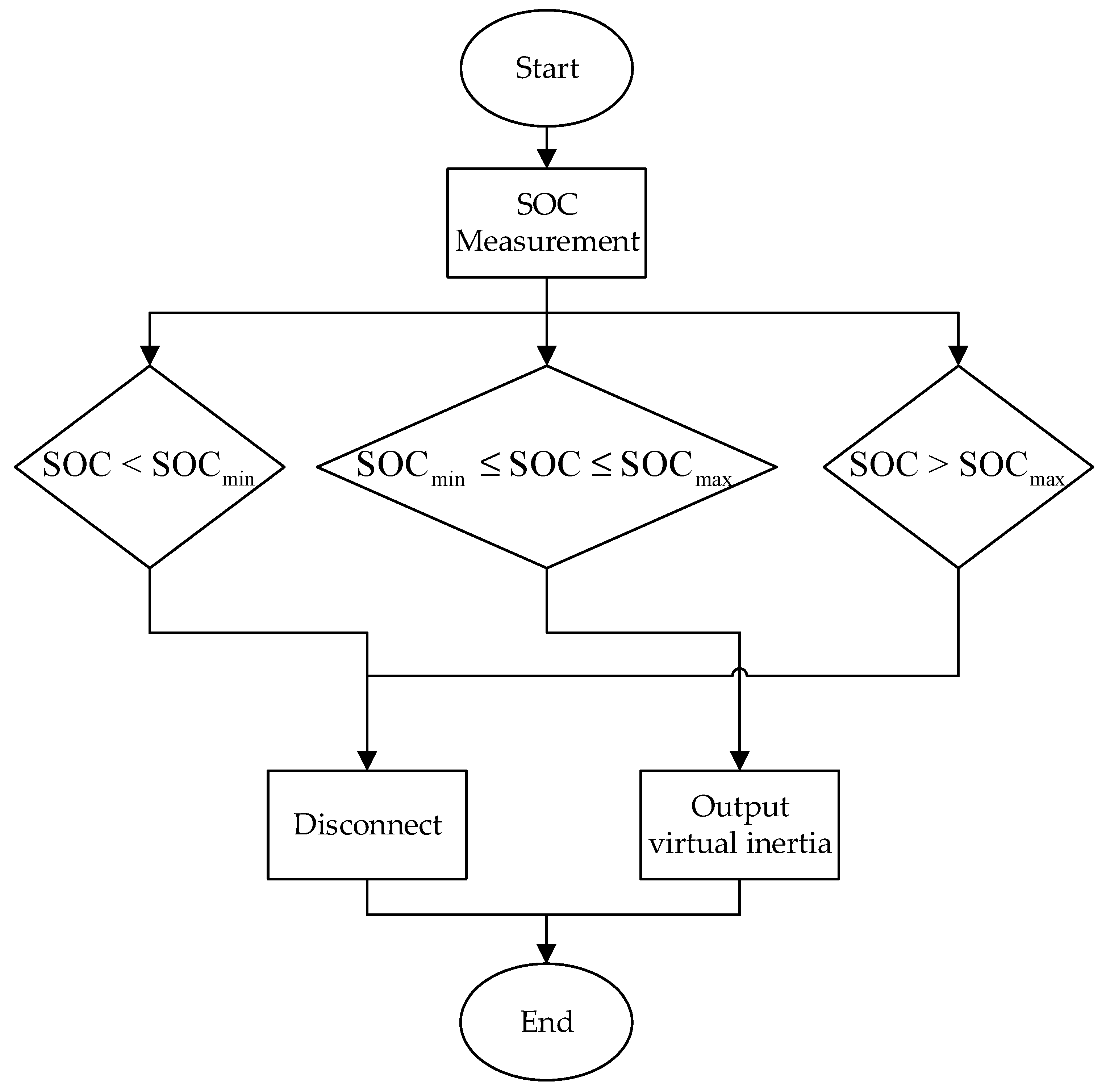
To ensure safe and reliable operation of the energy storage system (ESS) during virtual inertia support, the state of charge (SOC) must be effectively managed. In this study, an SOC-based discrimination mechanism is introduced to guarantee that the ESS operates within a predefined safety window. Specifically, the SOC is constrained within the range of 20–70%, which is widely recognized in the literature and industry standards as the optimal interval for maintaining battery health and ensuring stable energy output.
When the SOC remains within this safe range, the ESS is allowed to participate in frequency regulation and provide virtual inertia support in coordination with the wind turbine generator. Conversely, when the SOC exceeds 70% or drops below 20%, the system automatically suspends the virtual inertia function to prevent overcharging or deep discharging, thereby avoiding accelerated battery degradation and ensuring long-term operational reliability.
The overall control process is summarized in
Figure 1, which illustrates the logical flow of SOC discrimination and control decision-making. This mechanism not only enhances the operational safety of the ESS but also ensures that virtual inertia can be reliably supplied under varying grid conditions, particularly during transient events that demand rapid frequency support.
3. Power System Modeling of Combined Wind–Storage Systems
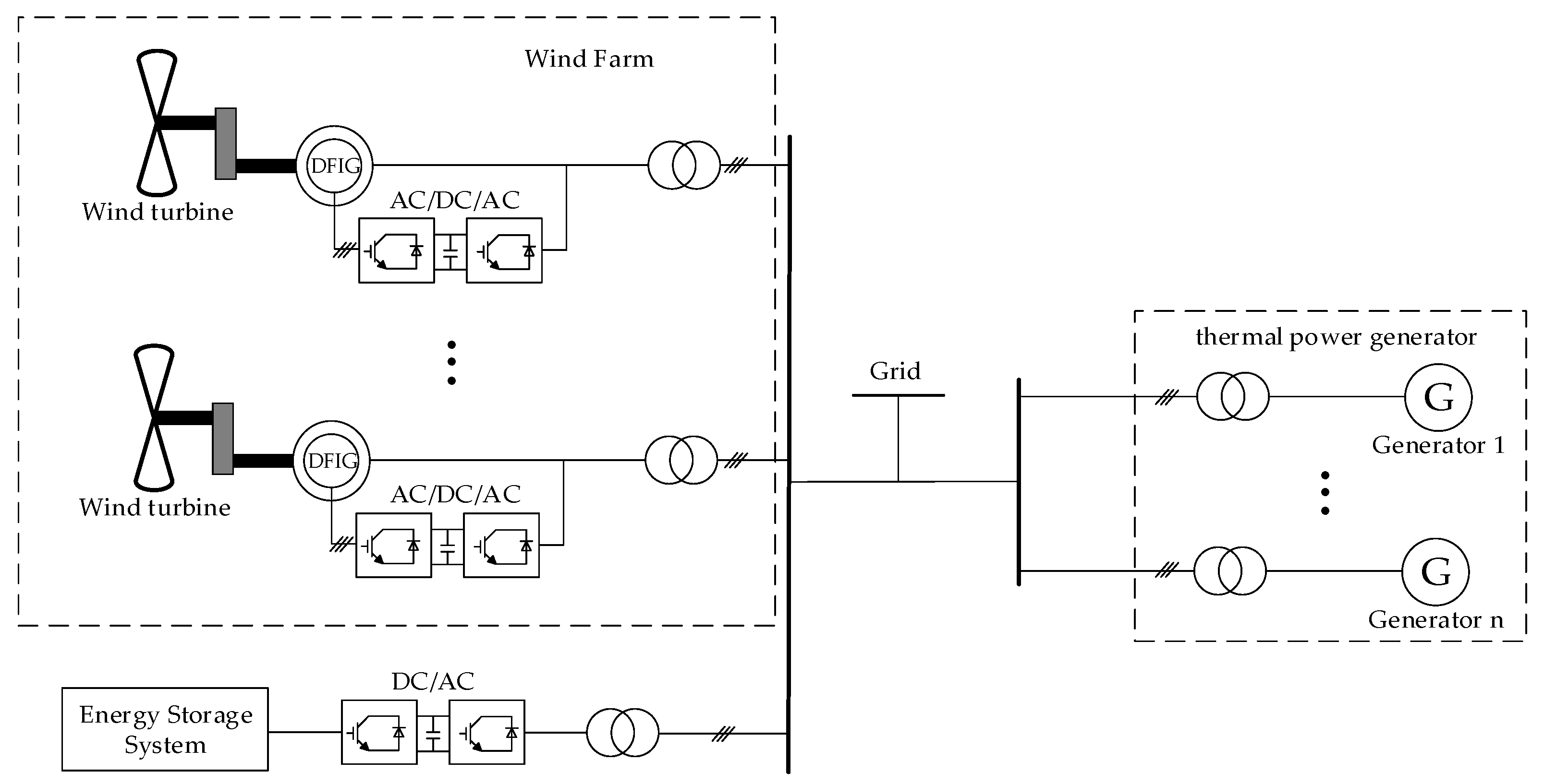
In the wind–storage hybrid system connected to the grid, the doubly-fed wind turbines of the wind power plant and the energy storage system are connected in parallel to a common bus, whereas the thermal generating units are connected to a separate bus. The two subsystems are subsequently integrated into the grid together, as illustrated in
Figure 2.
In the proposed virtual inertia control (VIC) framework, the converter dynamics are explicitly considered to capture the realistic frequency response behavior.
The converter can be modeled as a cascaded control system consisting of an inner current control loop, an outer active power control loop, and a virtual inertia control layer. The current control loop is typically designed with a high bandwidth, and its dynamics can be approximated by a first-order transfer function:
where
represents the time constant of the current loop.
The active power control loop is slower and dominates the dynamic interaction with the grid frequency.
Its dynamics are expressed as:
where
is the converter power-control time constant.
Integrating the virtual inertia control law:
the overall converter–VIC system can be represented as:
This formulation highlights that the converter time constants introduce phase delay and reduce the effective inertia response, especially during fast frequency transients.
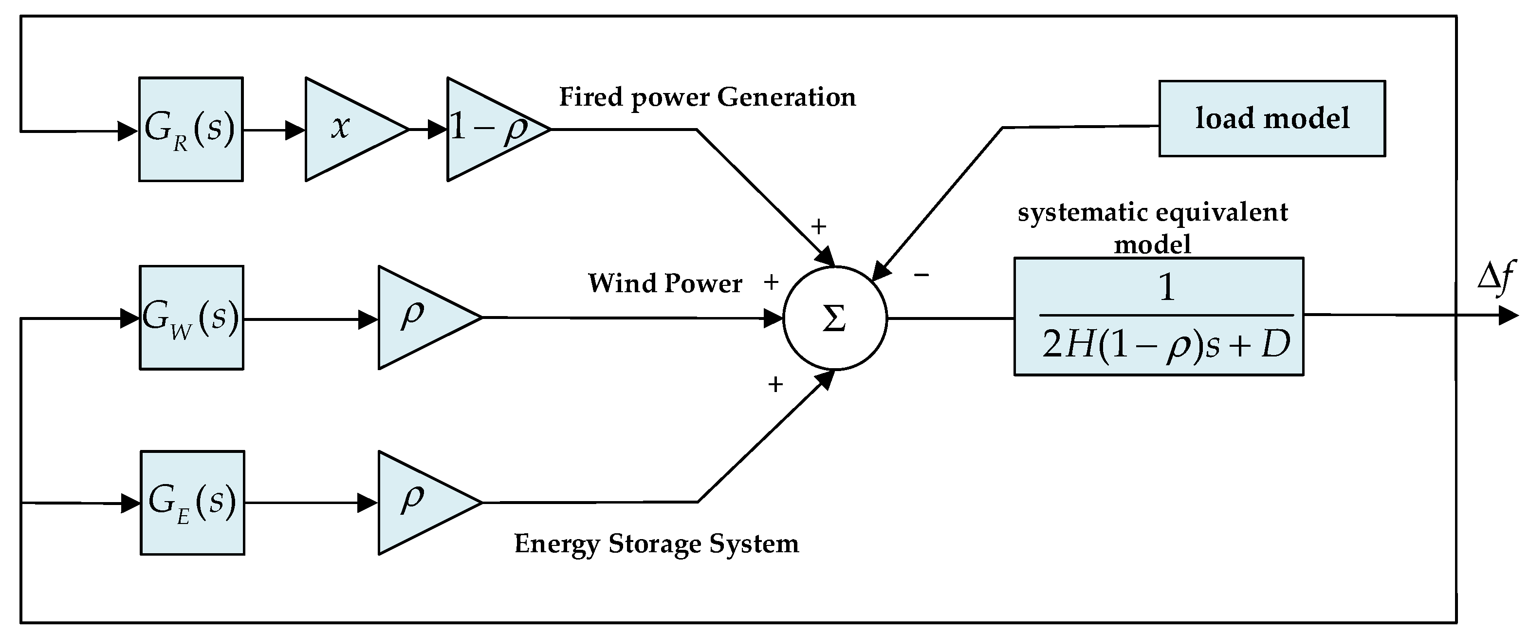
In the model building phase, four main aspects are involved: thermal power units, wind power units, energy storage systems and loads, and the overall linkage architecture is shown in
Figure 3. In the constructed power system model, the thermal power unit, wind power generation unit, and energy storage subsystem are all equipped with frequency feedback links that continuously monitor and exchange real-time frequency deviation signals across the system. These feedback mechanisms enable coordinated dynamic responses among the subsystems, ensuring that frequency fluctuations are effectively detected and compensated. As the principal contributors to the system’s equivalent inertia, these three components play a decisive role in shaping the overall frequency stability and transient response characteristics of the integrated power network.
3.1. Modeling of Thermal Power Units
The dynamic response of thermal power units during frequency regulation is governed primarily by the characteristics of their governor systems. In this study, four key elements are considered in the governor model: the frequency regulation dead zone, the regulation coefficient, the maximum output limit, and the response delay. Under normal system operation, frequency fluctuations are frequent but often minor. To avoid excessive and unnecessary actuation, a dead zone is introduced, within which no governor action occurs. In Chinese grid codes, the standard dead zone is typically specified as ±0.033 Hz.
Once the frequency deviation exceeds the dead zone threshold, the control signal is passed through a first-order inertia link, after which the steam valve control signal is generated based on the regulation coefficient. This signal is then constrained by the turbine’s rated power output limit.
The transfer function representing the dynamic behavior of the thermal governor is given by:
where
is the governor time constant (
, representing the inertia and delay inherent in the regulation process.
In terms of turbine modeling, steam turbines are generally classified as reheat and non-reheat types. Reheat turbines include additional high and intermediate-pressure stages, while non-reheat turbines adopt a simplified configuration, suitable for dynamic frequency analysis. In this study, the non-reheat turbine model is employed, with its dynamic behavior represented by a first-order transfer function:
where
is the turbine time constant.
As illustrated in
Figure 4 the change in mechanical power is obtained through the transfer function of the non-reheat thermal unit. This transfer function represents the turbine’s energy conversion dynamics within the thermal power system, linking the governor response to the resulting mechanical power output.
By cascading the governor and turbine models (Equations (16) and (17)), the overall transfer function of the thermal unit can be expressed as:
This composite model serves as the foundation for analyzing thermal unit responses to system frequency disturbances.
3.2. Generator–Load Dynamic Modeling
The generator–load model forms the core structure of dynamic frequency analysis in power systems, capturing the interaction between power generation and consumption. On the generation side, the model encompasses synchronous generators, renewable sources, and energy storage devices, each described by their respective control dynamics. On the demand side, both static loads and frequency-sensitive dynamic loads are considered.
The frequency dependence of load power is characterized by the load damping coefficient, which quantifies how load consumption varies with system frequency. This coefficient plays a critical role in evaluating frequency regulation performance, transient behavior, and system stability under renewable energy penetration.
The electromechanical dynamics of synchronous generators are traditionally described using the classical swing equation:
where
is the per-unit inertia constant (
),
is the rotor angular speed deviation,
is the change in mechanical input power,
is the change in electromagnetic output power.
The thermal unit is modeled as a first-order system representing the turbine governor and valve dynamics.
The linearized swing equation and governor model are given by:
where
is the governor droop,
is the governor time constant, and
,
are inertia and damping coefficients.
Applying the Laplace transform yields:
Assuming power balance, where
, and incorporating the load damping coefficient
, the load variation can be modeled as:
Substituting Equation (17) into Equation (16) yields the closed-loop dynamic model of the generator–load system:
This expression facilitates analytical evaluation of frequency response under disturbance conditions. The variation in mechanical power derived from
Figure 5 serves as one of the system inputs. The total power imbalance is then obtained by subtracting the load power from the input power through the inertia link, from which the corresponding change in rotor angular velocity is determined.
To ensure a fair comparison with the proposed wind–storage system, the conventional thermal generator is modeled with realistic governor characteristics, including a deadband of ±0.036 Hz, a turbine–governor time constant
, representing the mechanical response delay, and a control valve lag
accounting for actuator and hydraulic dynamics. With these considerations, the overall transfer function from frequency deviation (
) to mechanical power change (
) can be expressed as:
Time-domain simulations under a 0.2 p.u. load step show that including the deadband and response delays reduces the effective primary frequency response, leading to a slightly deeper frequency nadir (~0.03 Hz lower) compared to an idealized instant-response model. This ensures that the comparison reflects practical operational behavior.
3.3. Conventional Power System Frequency Response Model
The conventional power system frequency response model characterizes the dynamic behavior of the system under power imbalance conditions, primarily resulting from sudden changes in generation or load. This model integrates the core electromechanical dynamics of synchronous generators, the response behavior of their associated regulation systems, and the frequency sensitivity of electrical loads into a unified analytical framework.
At the heart of the model lies the rotor motion equation of synchronous generators, commonly referred to as the swing equation, which captures the fundamental relationship between rotor acceleration and the mismatch between mechanical input and electromagnetic output power. This relationship encapsulates the inertia time constant of the generator, which determines the system’s ability to resist rapid changes in frequency. Inertia, inherently provided by rotating masses, plays a crucial role in maintaining short-term frequency stability following disturbances.
Complementing the rotor dynamics, the frequency regulation process also involves the coordinated action of the governor and prime mover. These components are typically represented by first-order transfer functions, each introducing delay and smoothing in the response to frequency deviations. The governor modulates mechanical input based on frequency error, while the turbine (prime mover) translates this control into power adjustments with its own inherent time constant. Together, they form the dynamic frequency regulation path that governs how quickly and effectively power output can respond to frequency fluctuations.
In addition to the generator and control system dynamics, the model incorporates the frequency-dependent behavior of system loads. Most electrical loads exhibit a natural tendency to reduce consumption when system frequency drops, due to either inherent physical properties or embedded control logic in industrial devices. This phenomenon is characterized by the load damping coefficient, which introduces passive frequency stabilization into the system by offsetting a portion of the imbalance with a load-side response.
By integrating these three components—the generator’s rotor dynamics, the response characteristics of the speed regulation system, and the load’s frequency sensitivity—the conventional frequency response model forms a closed-loop system that governs the evolution of frequency over time. This integrated model accurately captures the transient frequency behavior of traditional power systems and serves as a theoretical foundation for frequency regulation strategies, stability assessment, and the design of control systems in conventional grid architectures. It is particularly relevant for benchmarking the performance of emerging renewable-integrated systems where rotational inertia is limited or emulated through synthetic means.
Through the derivations presented in the preceding subsections, the frequency response of the system can be obtained for the case where only thermal units are present in the conventional power grid. In this configuration, all inertia sources within the region—namely, the steam turbines—independently contribute both mechanical inertia and energy to the system. The net power input is determined by subtracting the load demand from the total generated power, and the resulting frequency deviation is calculated through the inertia link, as illustrated in
Figure 6.
3.4. Frequency Response Modeling of Wind–Storage Integrated Systems
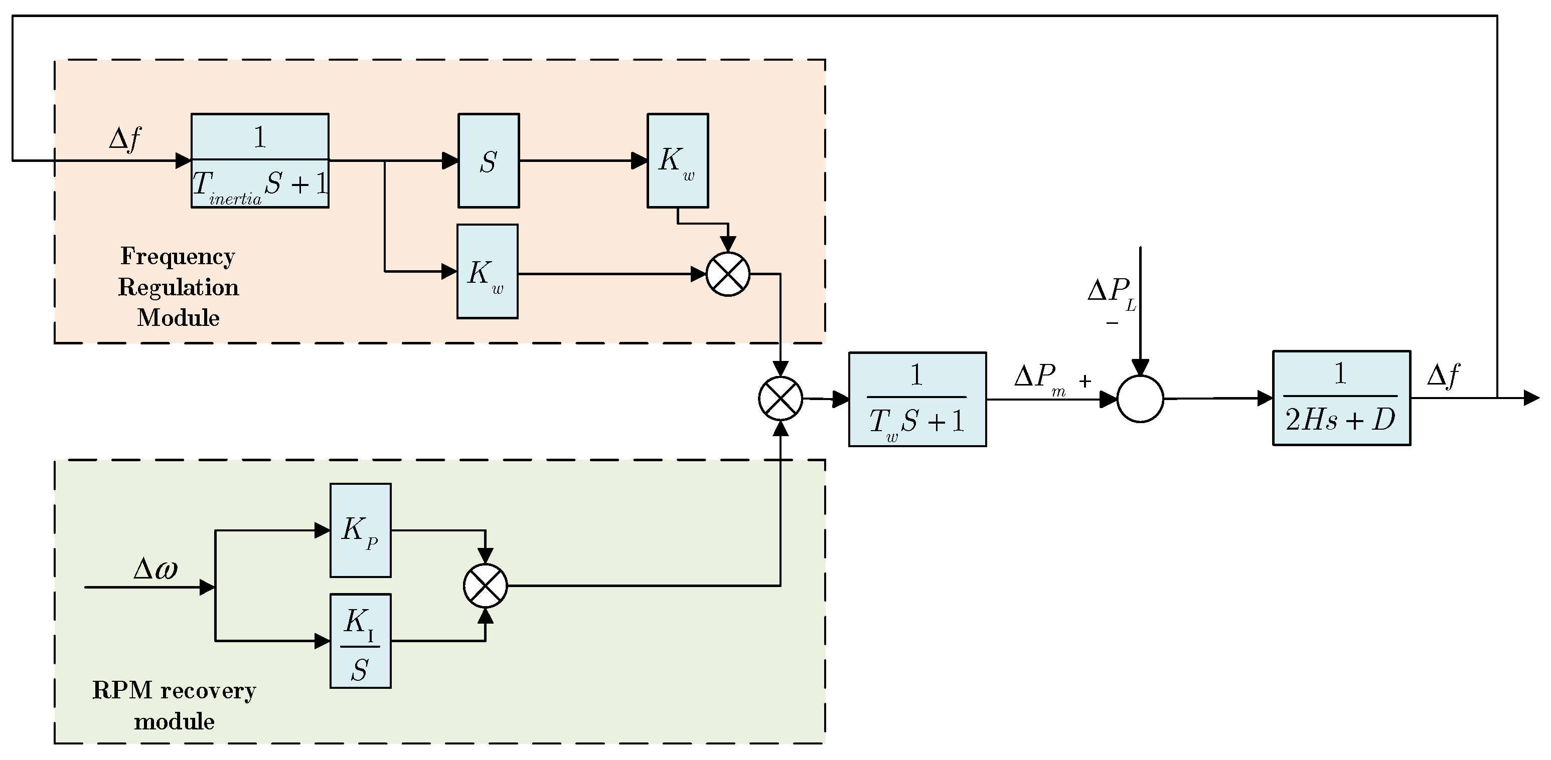
In this study, the wind generation component is modeled using a doubly-fed induction generator (DFIG), which is decomposed into two distinct modules: (1) a frequency regulation module, and (2) a rotor speed recovery module [
25].
The modular modeling approach allows for accurate representation of rotor speed adjustments and inertial response mechanisms during frequency deviations, the specific connection of the two modules is shown in
Figure 7.
The dynamic behavior of the battery energy storage system (BESS) in primary frequency regulation is modeled as:
where
is the response time constant of the storage system, reflecting the delay in its power output adjustment.
To realize the virtual inertia control strategy proposed in this paper, a first-order virtual inertia link is appended to the output of the energy storage system’s transfer function. This additional dynamic link enables the system to emulate the inertial response of a conventional synchronous generator, thereby enhancing the overall frequency stability of the grid. The specific implementation is expressed as follows:
where
is the response time constant of the virtual inertia, reflecting the effect of virtual inertia links on the system’s power–frequency dynamics.
Based on the aforementioned modeling and control principles, the final expression of the transfer function for the energy storage system is obtained as follows:
Through the derivation of the above transfer function, the relationship between power variation and frequency deviation can be established, yielding the analytical expression of the power–frequency characteristic.
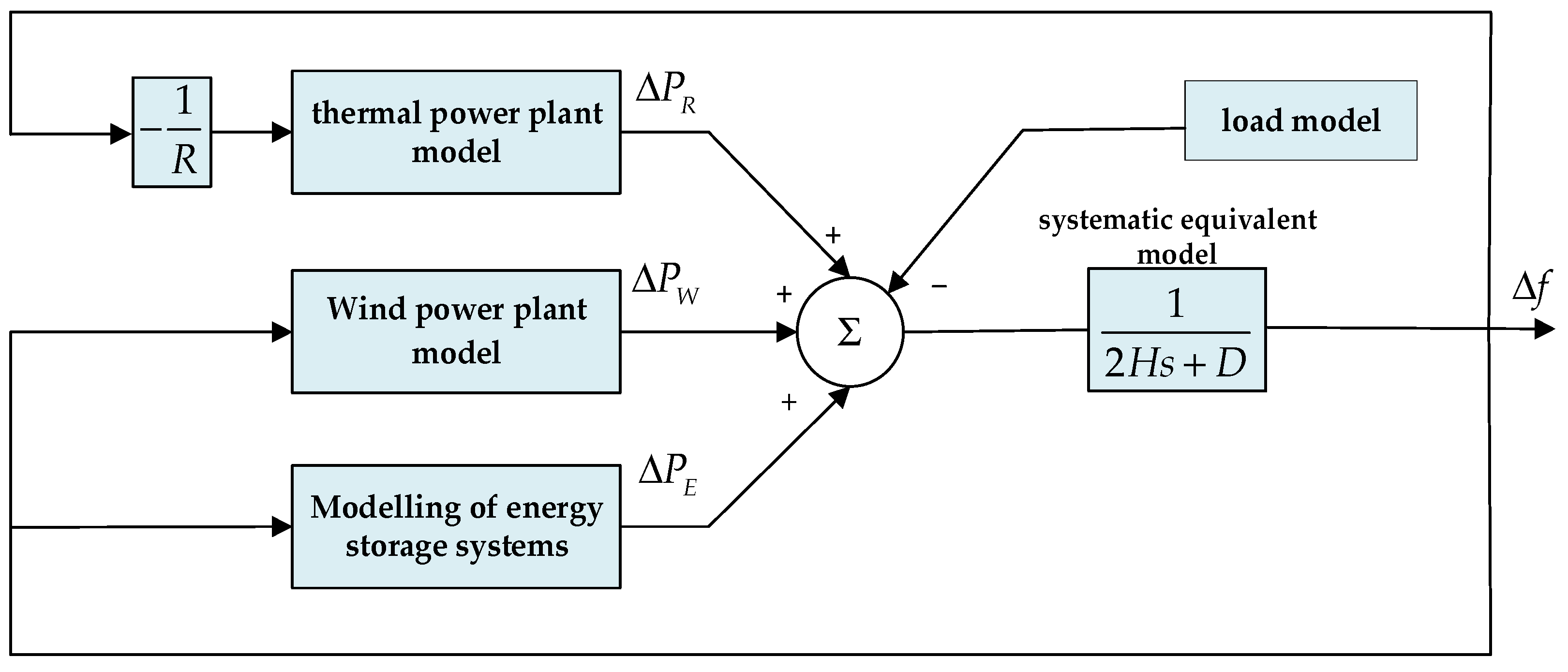
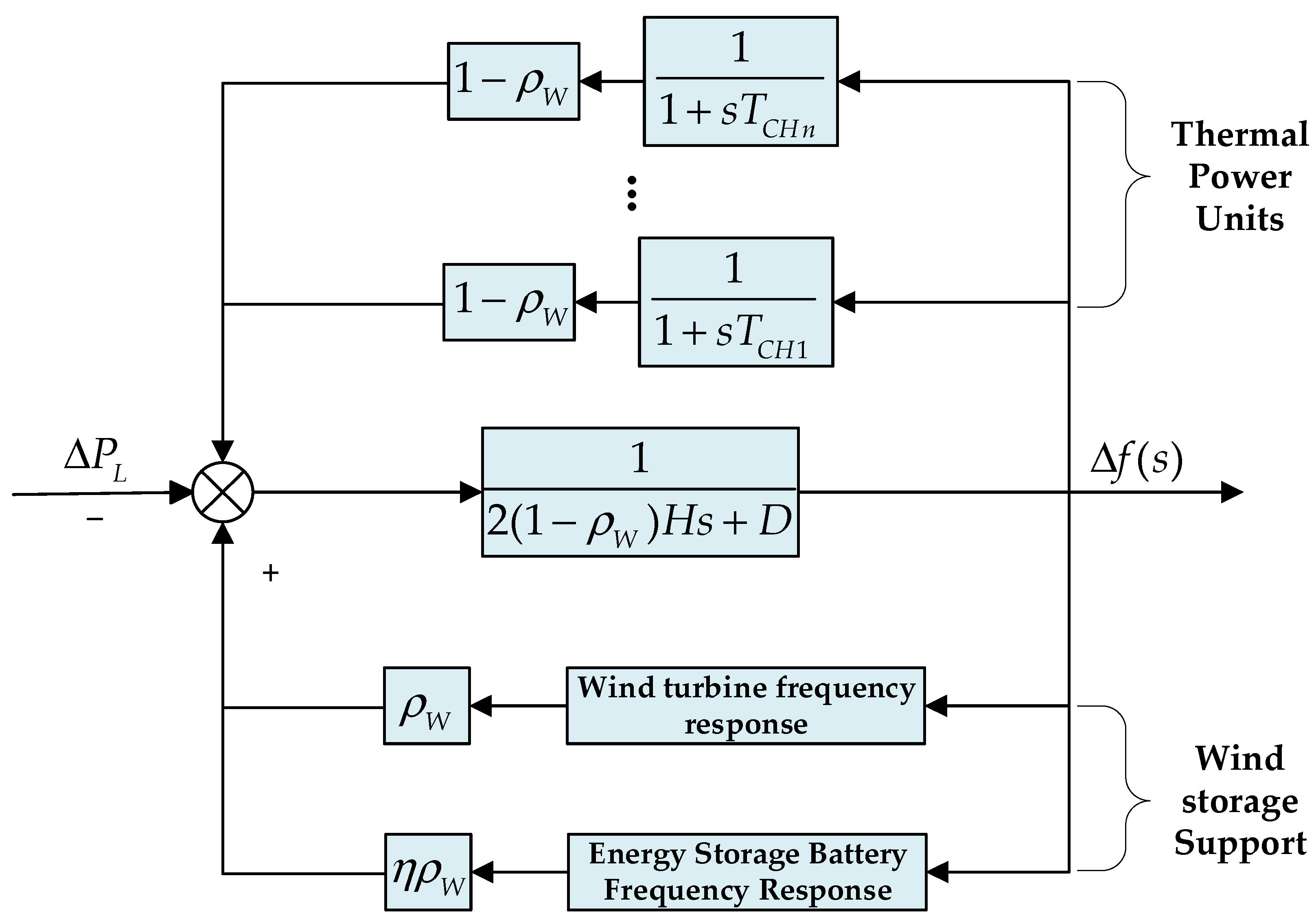
The enhanced frequency response model of the power system—accounting for contributions from both wind generation and energy storage—is illustrated in
Figure 8.
In conventional wind–storage hybrid systems, the primary source of system inertia is provided by thermal power units, with wind turbines contributing only a minor portion. However, as the proportion of renewable energy continues to increase, this inertia structure becomes inadequate, leading to insufficient overall system inertia. Consequently, the system’s ability to rely on inherent inertia for frequency stability under disturbances is significantly weakened. By incorporating a virtual inertia control link within the energy storage system, the effective inertia of the power grid can be enhanced, thereby enriching the system’s inertia sources and improving its frequency stability and disturbance resilience.
This integrated model reveals that under typical conditions, the wind turbine and BESS work in tandem to provide complementary frequency support. Notably, under extreme wind scenarios requiring wind turbine curtailment, the BESS independently provides sufficient frequency regulation capacity. This highlights the operational resilience and complementary value of storage in wind-dominated systems, underscoring its critical role in maintaining frequency stability under volatile renewable conditions.
4. Simulation Results and Discussion
4.1. Base Data
To assess the effectiveness of the proposed coordinated frequency regulation strategy, simulations are conducted on a single-area power system model. The system comprises one thermal generating unit rated at 600 MW, which includes 100 MW of spinning reserve, supplying a nominal load of 500 MW at 50 Hz. A 300 MW doubly-fed wind turbine and a 60 MW battery energy storage system (BESS) are integrated into the system to evaluate the contribution of renewable generation and storage to frequency regulation, as shown in
Table 1. The frequency regulation coefficient of the thermal unit is denoted as
, and the system dynamics are characterized by inertia constant
and damping coefficient
. 60 MW step load disturbance is introduced at
under all simulation scenarios. The disturbance scenarios considered in this study are described in detail, including the magnitude and duration of the load disturbances. It should be noted that the surge load is sustained throughout the simulation, as explicitly specified in the case study section. The wind speed is maintained at 12 m/s, corresponding to 50% wind energy penetration.
According to the model structure in the previous sections, the regional power system model required for validation is constructed, and the constructed regional model structure is shown in
Figure 9. The overall power system architecture was implemented in MATLAB/Simulink based on the developed transfer function models. The subsequent analysis demonstrates that the proposed wind–storage hybrid control strategy maintains system frequency stability even under extreme wind conditions, thereby verifying its robustness and superiority over conventional configurations.
4.2. Model Validation
To verify the effectiveness of the proposed control strategy, comparative simulations are conducted between two configurations of wind–energy storage hybrid systems. The first configuration integrates the virtual inertia control strategy proposed in this study, while the second configuration represents a conventional system without virtual inertia control, maintaining identical installed capacities, unit connections, and system parameters. This parallel design ensures that any observed performance differences can be solely attributed to the inclusion of virtual inertia control. In the subsequent validation section, the frequency regulation performance of both systems is comparatively analyzed under various operating conditions, including normal operation and extreme wind disturbances.
In the baseline case, only the thermal unit participates in frequency regulation. As shown in
Figure 10, following the load disturbance, the system frequency declines to a nadir of 49.76 Hz, corresponding to a deviation of 0.24 Hz. This value falls below the lower limit of the acceptable frequency range for secure operation (49.80–50.20 Hz), thereby posing a substantial threat to system stability. The result highlights the limitations of conventional thermal units in responding promptly to sudden disturbances due to their inherent response delays and limited control bandwidth. In low-inertia systems subject to frequent fluctuations, such as those associated with high renewable penetration or extreme weather events, reliance on thermal inertia and governor action alone proves inadequate.
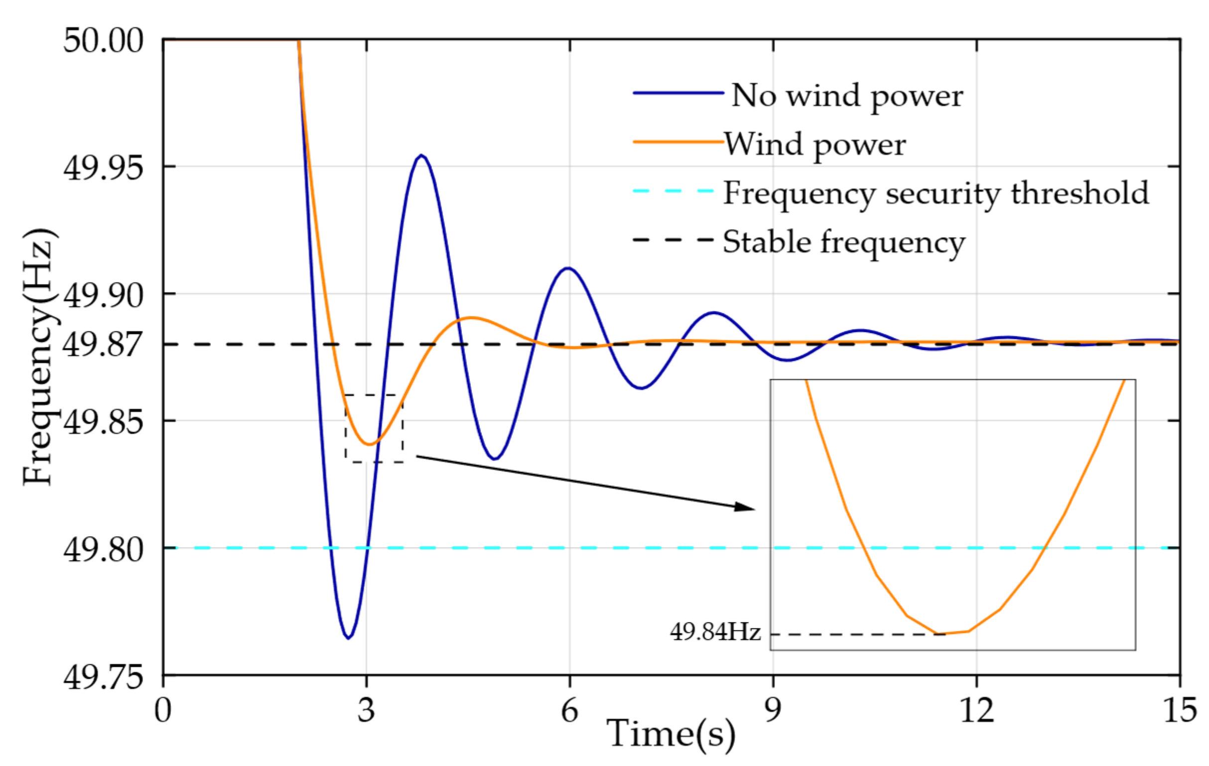
When wind power is enabled for frequency regulation via virtual inertia control, the system exhibits improved dynamic behavior. As illustrated in
Figure 11, the frequency nadir rises to 49.84 Hz under the same disturbance conditions, reducing the deviation to 0.16 Hz. This improvement is primarily attributed to the rapid release of rotor kinetic energy from the wind turbine during the initial phase of frequency decline. Through coordinated control of virtual inertia and over-speed operation, the wind turbine supplements the slower response of the thermal unit, effectively mitigating the frequency dip in the critical early moments following the disturbance.
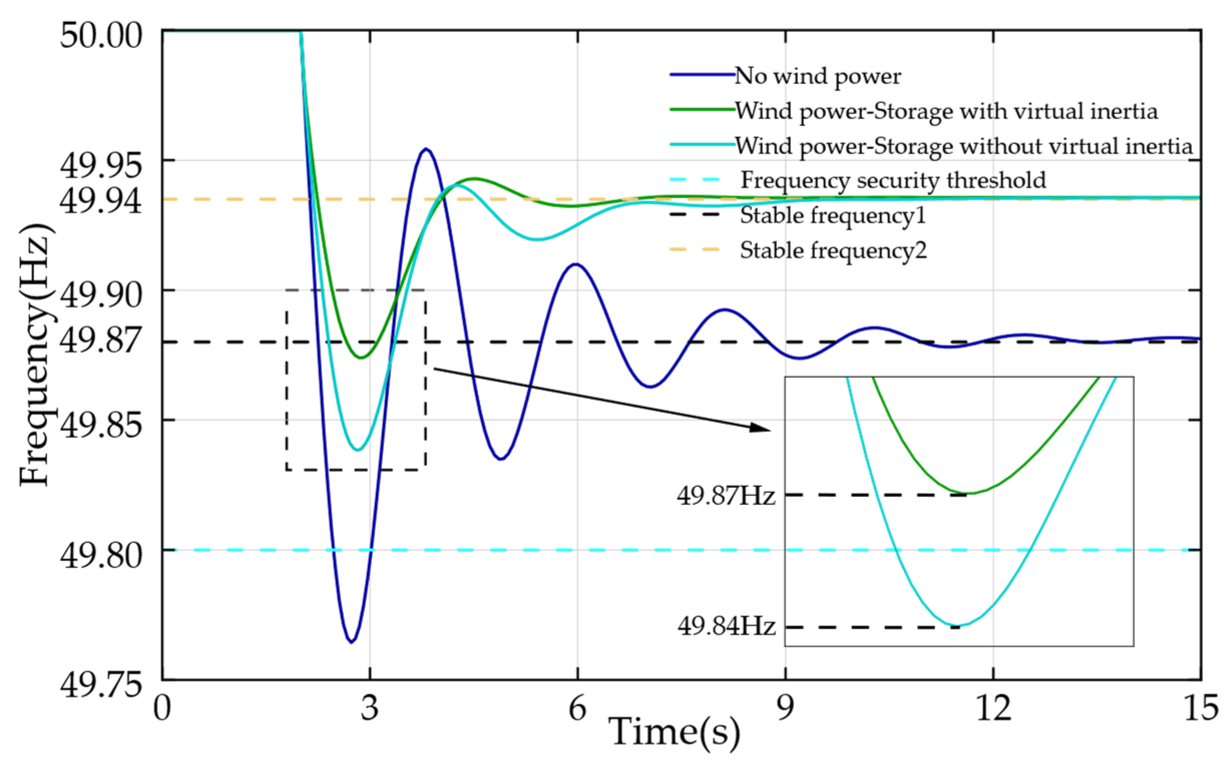
When wind turbines and battery energy storage systems (BESS) operate collaboratively for frequency regulation, the overall system performance is further enhanced. As illustrated in
Figure 12, under the coordinated virtual inertia wind–storage control strategy, the system’s minimum frequency rises to 49.87 Hz, while the steady-state frequency stabilizes at 49.94 Hz. In contrast, without the incorporation of virtual inertia, the steady-state frequency remains nearly identical; however, the minimum frequency drops to 49.84 Hz, indicating a comparatively weaker transient frequency response. These results demonstrate that the proposed wind–storage coordination strategy with virtual inertia satisfies operational requirements for both transient stability and steady-state frequency performance, outperforming the conventional scheme lacking virtual inertia. The superior performance of the proposed approach arises from the synergistic interaction between the millisecond-scale rapid power injection from the BESS at the onset of disturbances, the virtual inertia control that emulates synchronous generator dynamics, and the sustained inertial response of the wind turbines. This interaction forms a multi-timescale, cross-domain regulation framework that effectively reduces the frequency regulation burden on thermal units. Consequently, the proposed hybrid control strategy exhibits superior inertia emulation capability and achieves a higher minimum frequency nadir compared with traditional wind–storage hybrid systems without virtual inertia control, proving particularly effective in mitigating frequency risks under highly variable operating conditions.
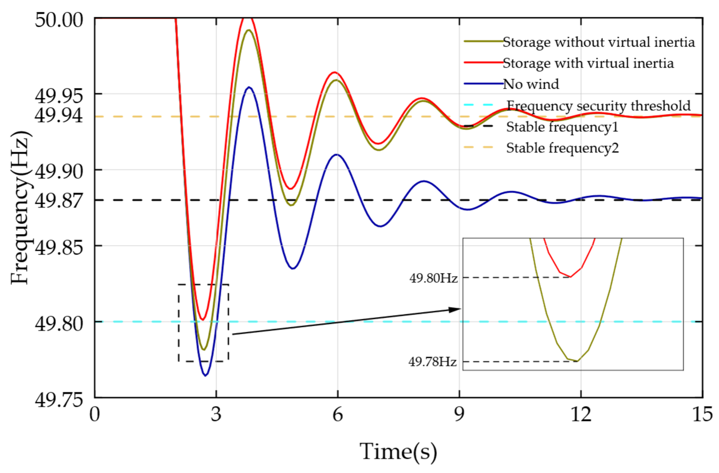
Finally, to validate the capability of the proposed wind–storage system to withstand extreme windy conditions, one of the most severe scenarios is considered: a large-scale wind turbine outage in a wind farm subjected to extreme winds. Under this scenario, the frequency modulation strategy implemented by the wind–storage system effectively regulates the system frequency, demonstrating the robustness of the coordinated control approach in mitigating frequency deviations during extreme events.
As illustrated in
Figure 13, under this operating condition, the system frequency of the wind–energy storage hybrid system equipped with virtual inertia control drops to a minimum of 49.80 Hz, remaining within the prescribed safety boundary. In contrast, the corresponding system without virtual inertia control experiences a slightly deeper frequency nadir of 49.78 Hz, which falls below the safe operating limit. This comparison clearly demonstrates that the wind–energy storage hybrid system with virtual inertia control provides superior frequency regulation performance under extreme conditions. The results underscore the critical role of incorporating virtual inertia in energy storage systems for maintaining grid stability during extreme weather events that may lead to large-scale renewable energy disconnections. Furthermore, the findings validate that the proposed BESS control strategy exhibits greater robustness than conventional approaches and effectively enhances the system’s resilience against high-impact disturbances.
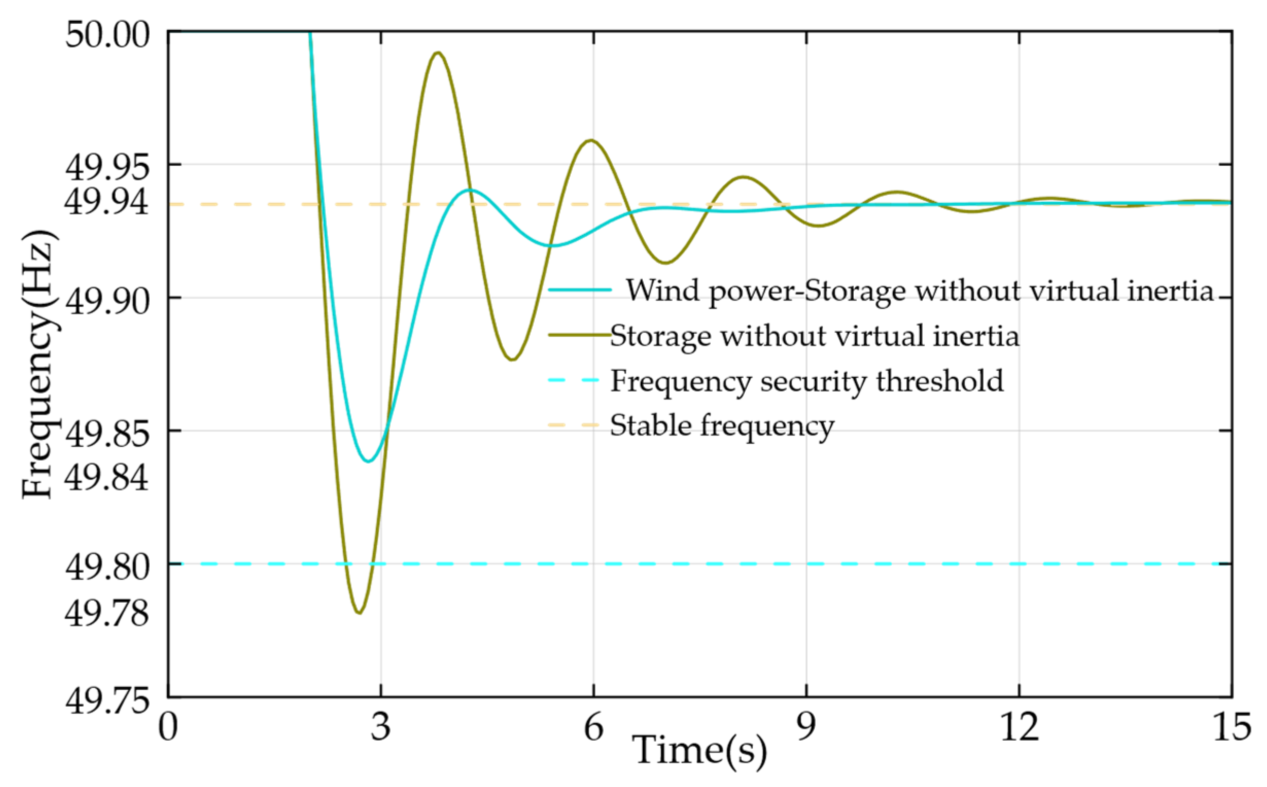
Up to this stage, the coordinated frequency regulation strategy proposed in this study has undergone comprehensive validation within the constructed high-wind-penetration power system model, with the regulation performance exhibiting close agreement with the predicted theoretical behavior. The validation framework considers two representative operating scenarios: coordinated wind–storage regulation with the wind turbine in service under nominal wind speed conditions, and coordinated regulation with the wind turbine disconnected under high-wind cut-out conditions.
Figure 14 and
Figure 15 presents the complete frequency trajectories under both normal and extreme wind conditions, with the minimum frequency remaining above 49.8 Hz in all cases. This clearly demonstrates the robustness of the proposed model in maintaining system stability under extreme wind events.
The frequency response trajectories in
Figure 14 and
Figure 15 indicate that under nominal wind conditions, the coordinated wind–storage system with virtual inertia maintains a minimum frequency of 49.87 Hz, and 49.80 Hz during turbine tripping events. In contrast, the system without virtual inertia exhibits minimum frequencies of 49.84 Hz and 49.78 Hz, respectively, demonstrating the superior transient frequency support provided by virtual inertia. These results confirm the strategy’s effectiveness in enhancing inertial response and primary frequency regulation in grids with high renewable penetration. The developed dynamic model accurately captures electromechanical and electrochemical interactions, enabling precise prediction of multi-timescale responses and providing a solid foundation for advanced frequency stability assessment and optimal control designs.
4.3. Assessment of Frequency Regulation Capacity
Through comprehensive validation, the minimum frequency and steady-state frequency deviations of the system under various grid-connection configurations and operating conditions were obtained, as summarized in
Table 2. As shown, when the regional power system relies solely on the inherent inertia of synchronous generators to counteract frequency deviations induced by sudden load increases, the resulting minimum frequency falls outside the safe fluctuation range specified by operational frequency regulation standards. Similarly, wind–storage systems without virtual inertia are inadequate to address the full spectrum of complex frequency regulation scenarios. These results clearly demonstrate that the incorporation of virtual inertia from wind turbines and energy storage systems significantly enhances the system’s dynamic frequency support capability.
However, the steady-state frequency exhibits no significant improvement in this case. By contrast, when the system incorporates the coordinated wind–storage frequency regulation mechanism, both wind turbines and the battery energy storage system (BESS) contribute additional synthetic inertia and fast active power support through advanced control strategies. This results in a pronounced increase in the nadir frequency during load disturbances, alongside a marked enhancement in steady-state frequency recovery compared to the first two cases. Even under the extreme scenario of wind turbine cut-off during severe wind events, the coordinated wind–storage system maintains the minimum frequency within the prescribed secure operating range. These results provide quantitative validation that the integrated wind–storage model plays a critical role in augmenting the effective system inertia, thereby reinforcing frequency resilience and ensuring robust stability under high renewable penetration conditions.
Overall, the simulation results demonstrate the progressive improvement in frequency regulation performance as control participation evolves from thermal-only, to wind-assisted, and finally to fully coordinated wind–storage operation. The study also confirms the capacity of BESS to independently fulfill frequency support roles under emergency conditions. The proposed modeling and control framework accurately captures these dynamic behaviors and provides a reliable foundation for designing frequency regulation strategies in future low-inertia, high-renewable power systems.
