Article

Enhancing Breakdown Field Strength and Energy Density in Sandwich-Structured P(VDF-HFP)/BT Films with BN Coating

1
State Grid Shanxi Electric Power Research Institute, Taiyuan 030012, China
2
College of Electrical and Power Engineering, Taiyuan University of Technology, Taiyuan 030024, China
*
Author to whom correspondence should be addressed.
Processes 2025, 13(10), 3295; https://doi.org/10.3390/pr13103295
Submission received: 11 September 2025 / Revised: 7 October 2025 / Accepted: 11 October 2025 / Published: 15 October 2025
(This article belongs to the Special Issue Fiber-Reinforced Composites: Latest Advances and Interesting Research)

Abstract

With the rapid development of communication, electronics, medical, and energy industries in modern society, film capacitors have garnered widespread attention and undergone significant growth. However, the low energy density (Ue) resulting from low breakdown strength (Eb) significantly limits the application of thin-film capacitors. In this work, we use a low-cost and effective dip-coating method to apply boron nitride (BN) layers onto the outer layers of poly(vinylidene fluoride-co-hexafluoropropylene)/barium titanate (P(VDF-HFP)/BT) composite films to prepare boron nitride-poly(vinylidene fluoride-co-hexafluoropropylene/barium titanate-boron nitride (BN-P(VDF-HFP)/BT-BN) composite films with a sandwich structure that exhibits extremely high Eb and Ue. The experimental results show that the sandwich-structured BN-P(VDF-HFP)/BT-BN films containing 7.5 wt% BT nanoparticles obtained 530 MV/m Eb and 18.12 J/cm3 Ue, both of which are much higher than those of the corresponding monolayer films. In addition, the finite element simulation results show that the designed sandwich-structured films can reduce local field strength distortion, decrease leakage current, and suppress the development of breakdown channels, thereby significantly improving Eb and Ue. In summary, this study presents a low-cost and effective method for enhancing the breakdown strength and energy density of thin-film capacitors.

1. Introduction

As an indispensable part of power electronics systems, film capacitors offer the advantages of high breakdown strength, high power density, and low preparation cost. Therefore, film capacitors can be used in various types of circuits, typically for high-frequency power inverters and direct current converters [1,2,3]. The performance and lifespan of film capacitors mainly depend on the dielectric materials. Among all types of dielectrics, polymer dielectrics are ideal materials for high-energy-density capacitors due to their low dielectric loss, high breakdown voltage, scalability, and reliability [4]. However, their low dielectric constant limits the application of polymer film capacitors in many areas. For example, commercial biaxially-oriented polypropylene (BOPP) exhibits a low energy density (~5 J/cm3), which is restricted by its low dielectric constant (generally <3) [5]. The low energy storage density of polymer capacitors cannot meet the requirements of miniaturization, lightness, and integration of electronic devices; therefore, the development of dielectrics with unprecedented energy density is highly requested [6]. For linear dielectrics, the energy density Ue is described as follows:
U e = 0.5 ε 0 ε r E b 2
where ε0 is the dielectric constant of vacuum, εr is the relative dielectric constant of polymer, and Eb is the breakdown electric field strength [7].
εr and Eb are two key parameters used to assess energy density. However, the contradiction between εr and Eb will limit the enhancement of Ue, posing a significant challenge that needs to be addressed. Currently, the typical strategy is to blend ceramic fillers that have a high dielectric constant with a polymer to prepare nanocomposites [8]. For the polymer, poly(vinylidene fluoride) (PVDF) and its copolymers with a highly polar C-F bond have been widely studied, including poly(vinylidene fluoride-hexafluoropropylene) (P(VDF-HFP)), poly-(vinylidene fluoride-trifluoroethylene-chlorotrifluoroethyle) (P(VDF-TrFE-CTFE)), and so on [9,10,11]. High-dielectric-constant ceramic particles, such as barium titanate (BT), potassium titanate (K1.6Fe1.6Ti6.4O16), calcium copper titanate (CCTO), and so on, are considered excellent nanofillers [12,13,14,15]. Although blending various ceramic particles can increase the dielectric constant of nanocomposite dielectrics, it also leads to a new problem: the aggregation of particles will cause electric field distortion and form local high-conductivity regions, resulting in an increase in leakage current density and a decrease in Eb, which ultimately limits the further improvement of energy storage density.
To enhance the insulation performance and energy storage density, some 2D ceramic materials with high band gaps, such as hexagonal boron nitride (h-BN), montmorillonite (MMT), and silica (SiO2), are incorporated into polymers [16,17,18]. Ceramic fillers used in composites can be classified into granular grains, nanofibers (1D), and nanosheets (2D). Compared with granular grains and 1D materials, 2D nanosheets have lower dielectric loss and higher breakdown voltage. Hexagonal boron nitride (BN), a typical 2D ceramic material, possesses a layered structure similar to that of graphite and has been introduced in reported strategies to improve the Eb and decrease energy loss [19]. However, the energy storage performance of single-layer ceramic/polymer nanocomposites still falls short of meeting the requirements for commercial applications. The emergence of layer-structured design introduces an effective method to resolve the paradox between high Eb and enhanced εr in ceramic/polymer nanocomposites [20,21]. It has been reported in some of the literature that inorganic insulation layers are attached to the polymer surface via Chemical Vapor Deposition (CVD) to enhance the performance of composite films [22,23]. However, the CVD process is complicated. In this study, we propose and adopt a low-cost dip-coating method to obtain sandwich-structured composite films consisting of two BN outer layers with a P(VDF-HFP)/BT film in between to enhance the Eb and Ue and reduce the electrical loss of nanocomposites. This method not only improves the performance of materials but also has significant application value due to its economic and safety benefits.

2. Materials and Methods

2.1. Materials

Poly(vinylidene fluoride-hexafluoropropylene) (P(VDF-HFP), 10% HFP) was purchased from Arkema, France. N, N-dimethylformamide (DMF, AR, 99.5%) was procured from Macklin, Shanghai, China. Barium titanate (BT, <100 nm), polyvinyl butyral (PVB), and boron nitride (BN, 1–2 μm) were obtained from Aladdin, Shanghai, China.

2.2. P(VDF-HFP)/BT Films

Figure 1 illustrates the process for preparing sandwich-structured BN-P(VDF-HFP)/BT-BN films. Firstly, BT nanoparticles (NPs) dispersed into DMF were ultrasonicated for 1 h. Then, P(VDF-HFP) powders were added to the DMF and quickly stirred for 12 h at 30 °C until a stable mixed suspension formed. Next, the suspension was covered on glass substrates to obtain the thin-film-like P(VDF-HFP)/BT composites. During preparation, film thickness can be controlled by changing the scraper height. After casting, the P(VDF-HFP)/BT films were dried at 130 °C for 12 h in a vacuum oven to remove the DMF solvent. Films were quenched in ice water after being heated at 200 °C for 25 min. Finally, flexible freestanding P(VDF-HFP)/BT films were obtained after they were dried at 80 °C for 12 h and peeled from the glass substrates. For comparison, P(VDF-HFP)/BT films with different mass contents of BT NPs were prepared. The mass fractions of BT NPs in P(VDF-HFP)/BT films were 2.5 wt%, 5 wt%, 7.5 wt%, 10 wt%, 20 wt%, and 30 wt%, respectively. Films are denoted as “x wt% BT”, where x is the mass fraction of BT NPs. For example, 2.5 wt% BT refers to the P(VDF-HFP)/BT film with 2.5 wt% BT NPs.

2.3. Preparation of Sandwich-Structured Films

The sandwich-structured BN-P(VDF-HFP)/BT-BN films were obtained by coating BN layers on the top and bottom surfaces of the P(VDF-HFP)/BT films. Firstly, 0.5 g of BN powder was dispersed in ethanol solution under ultrasonication for 1 h. Subsequently, 0.5 g of PVB was added to the BN solution and stirred for 12 h at 30 °C. Then, the suspension was further mixed under ultrasonication for 1 h to obtain the BN coating precursor solution. After removing the P(VDF-HFP)/BT films from the glass substrates, they were placed vertically in the BN coating precursor solution for 1 min and slowly pulled up. Finally, films were hung on a drying rack and dried at 60 °C for 12 h. The sandwich-structured BN-P(VDF-HFP)/BT-BN films were denoted as BN-x-BN. For example, BN-2.5-BN refers to a P(VDF-HFP)/BT film with 2.5 wt% BT between two outer layers of BN films.

2.4. Characterization

The morphologies of the P(VDF-HFP)/BT films and sandwich-structured BN-P(VDF-HFP)/BT-BN composite films were studied by scanning electron microscopy (SEM) (Tescan Vega3SBU, Brno, Czech Republic). X-ray diffraction (XRD) (Bruker D8 Advanced, Karlsruhe, Germany) was used to analyze the crystal structures of all films. After the films were sputtered with gold electrodes of a 2 mm diameter on both sides, the dielectric constant and loss tangent were measured using a Novocontrol Concept 80, Montabaur, Germany, over a frequency range from 102 Hz to 107 Hz. The breakdown electric field strength was measured under DC voltage. The energy density and charge–discharge efficiency of the samples were acquired using electric displacement vs. electric field (D-E) loops, which were measured with a modified Sawyer–Tower circuit at 10 Hz.

2.5. Finite Element Analysis and Breakdown Process Simulation

To analyze the effect of BN coating on the insulation properties of BN-P(VDF-HFP)/BT-BN films, finite element analysis, and simulation of the electric field and leakage current density distribution of 7.5 wt% BT and BN-7.5-BN were carried out. In this simulation, the top was set to high voltage, the bottom was set to ground, and the left and right boundaries were set to electrical insulation. The electric field and the leakage current density were solved by Gauss’s law and continuity equations:
ε 0 ε r E = ρ
J = ρ t
J = σ E
where ε0 is the vacuum dielectric constant, εr is the relative dielectric constant, E is the local electric field, ρ is the charge density, J is the current density, and σ is the electrical conductivity at DC stresses.
In addition, to further reveal the important role of the BN layer in enhancing Eb, the development of breakdown channels in films was visualized by the phase field model based on the work of Hong and Cai et al. [24]. In this model, a continuous scalar phase field s(x, t) (s ∈ [0, 1]) was introduced to characterize the degree of damage in the dielectric. The damage to the dielectric was reflected in the dielectric properties. To show the process of gradual deterioration of the material with breakdown propagation, the phase field method assumes that the relative dielectric constant of the material in different damage states is different, which can be written as follows:
ε s = ε 0 f s + η
where f(s) = 4s3 − 3s4, ε0 is the initial dielectric constant of the material, and η is a small enough number with a value of 0.001 [25]. It can be seen that when s = 1, ε = ε0/(1 + η), which is approximately equal to the initial dielectric constant of the material, indicating that it is in an intact state. However, when s = 0, ε = ε0/η, the value is very large, which means that the material is broken down into a conductor at this moment. This part is given a very high relative dielectric constant, which reflects the strong polarization and insulation performance of the material after breakdown due to charge accumulation. The governing equations of the growth and propagation process of the conductive channel are
ε s ϕ = 0 ε s ϕ
1 m s t = ε s 2 ϕ ϕ + W c f s + Γ 2 2 s
where φ is the electric potential, m is the breakdown mobility, t is the time, Wc is the critical density of electrostatic energy, and Γ is the approximate breakdown energy.
Since the focus of the simulation was to study the reason and mechanism for improvement in the insulation performance of the BN coating on the whole nanocomposite, all the simulations were performed in the two-dimensional (2D) domain. All models realized the random distribution of nano-fillers in the matrix.

3. Results and Discussion

Figure 2a shows SEM images of the P(VDF-HFP)/BT films with different contents of BT. With the increase in BT content, the distance between BT NPs decreased. When the BT content was approximately 30 wt%, the agglomeration phenomenon became evident. The fracture morphology of BN-7.5 wt% BT/P(VDF-HFP)-BN films is shown in Figure 2b. It can be seen that the film exhibited a sandwich structure with a total thickness of about 302 μm. The outermost layer was a BN layer with a thickness of about 5 μm, and the middle layer was a BT/P(VDF-HFP) layer with a thickness of about 20 μm. Figure 2c shows the surface microstructure of the BN-BT/P(VDF-HFP)-BN nanocomposite. It can be seen that the layered BN nanosheets were successfully coated on the surface of BT/P(VDF-HFP) films. In summary, the sandwich-structured BN-BT/P(VDF-HFP)-BN films were successfully prepared by the method described in Section 2.3.
Figure 3a shows the XRD patterns of BN, BT, pure P(VDF-HFP), BT/P(VDF-HFP) film, and BN-P(VDF-HFP)/BT-BN film. The typical characteristic patterns of tetragonal-structured BT clearly observed at 2θ = 22.1°, 31.4°, 38.7°, 45.04°, 50.7°, 56°, and 65.6° were indexed to the (100), (110), (111), (200), (210), (211), and (220) planes, respectively. The similar typical characteristic patterns of the P(VDF-HFP)/BT films could be seen in those of BN-P(VDF-HFP)/BT-BN films. It can be observed in Figure 3a that three characteristic patterns were obviously located at 18.4°, 19.8°, and 26.7°, which correspond to the γ(020), γ(110), and γ(022) phases in pure P(VDF-HFP) film. However, the XRD patterns of the BT/P(VDF-HFP) films and BN-BT/P(VDF-HFP)-BN films only showed weak γ(020) and γ(110) phases with peaks at 18.4° and 19.8°. As shown in Figure 3a, the sandwich-structured BN-P(VDF-HFP)/BT-BN films consisted of not only P(VDF-HFP)/BT as the main body but also BN thin film as the outer layer, which was verified by the pattern at 2θ = 26.7°, referring to the (002) crystal plane.
Figure 3b,c show the variations in the dielectric constant and loss tangent of the P(VDF-HFP) and BN-P(VDF-HFP)/BT-BN films at 30 °C over a frequency range from 102 Hz to 107 Hz. Figure 3b shows that the dielectric constant of all samples decreased with increasing frequency, which was caused by the delayed response of the dipole moment. In addition, the dielectric constant and loss tangent of the BN-P(VDF-HFP)/BT-BN films increased with the increase in BT nanoparticle content. This is attributed to the high dielectric constant of BT. On the one hand, the overall dielectric constant of the P(VDF-HFP) and BN-P(VDF-HFP)/BT-BN films became higher. On the other hand, it increased the polarization intensity and led to an uneven distribution of the electric field, resulting in increased polarization loss and conduction loss, particularly at high frequencies.
Figure 3d shows a comparison of the dielectric constant and loss tangent of all films filled with different contents of BT NPs at a frequency of 104 Hz. Apparently, the dielectric constant and loss tangent of all BN-P(VDF-HFP)/BT-BN films decreased compared to those of P(VDF-HFP)/BT films. The loss tangent values of the BN-P(VDF-HFP)/BT-BN films were all below 0.02. The addition of BN-coating layers can effectively inhibit the injection of electrons into films at the electrode, similar to the formation of a barrier around the P(VDF-HFP)/BT film, thereby reducing the leakage current density and conduction loss. Meanwhile, the polarization degree of the composite material was reduced after BN coating was applied, so the polarization loss and dielectric constant were also reduced accordingly.
In addition to dielectric performance, breakdown strength is an essential element for the energy storage performance of composites. The breakdown strength of composites is analyzed by the Weibull distribution, expressed as follows:
P ( E ) = 1 exp ( ( E E b ) β )
where P(E) represents the cumulative failure probability; E is the measured breakdown strength; Eb is the calculated breakdown strength when the cumulative failure probability is 63.2%; and β is the shape parameter used to evaluate the measure of dispersion.
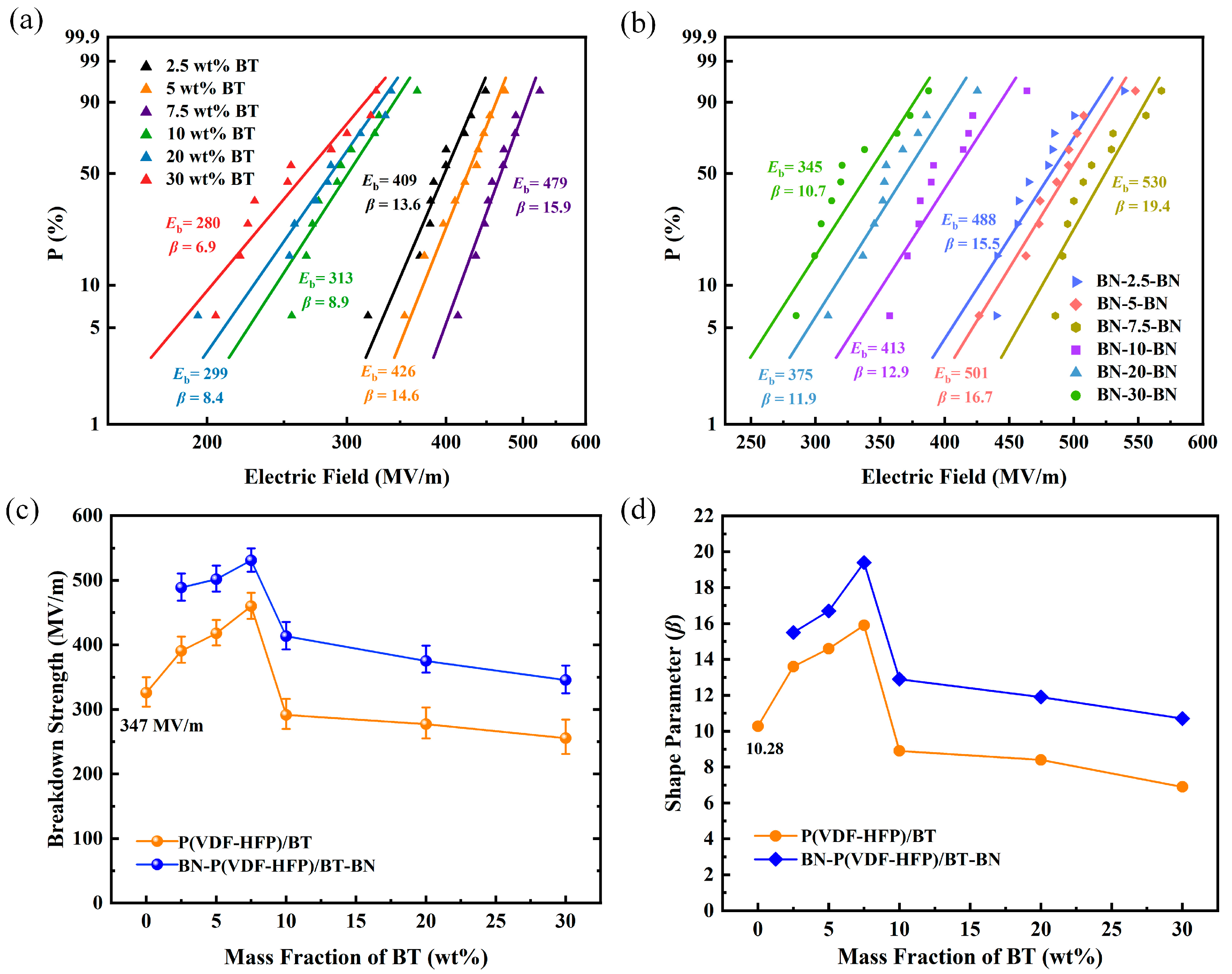
The Weibull distributions of the P(VDF-HFP)/BT and BN-P(VDF-HFP)/BT-BN films are shown in Figure 4a,b. The breakdown strength first increased and then decreased with the increase in BT NP filler content because more structural defects were introduced when the mass fraction of BT NPs exceeded 7.5 wt%, such as micropores and agglomeration. Figure 4c,d show the breakdown electric field strength Eb and the shape parameter β of the P(VDF-HFP)/BT and BN-P(VDF-HFP)/BT-BN films. The 7.5 wt% BN-P(VDF-HFP)/BT-BN nanocomposite had the largest Eb and β values of 530 MV/m and 19.4, respectively. The Eb and β of the BN-P(VDF-HFP)/BT-BN nanocomposite were higher than those of the samples without BN coating. Eb of the BN-P(VDF-HFP)/BT-BN nanocomposite was about 1.53 times that of pure P(VDF-HFP) (347 MV/m). Thanks to the BN-coating layers, the sandwich-structured nanocomposite exhibited a relatively high dielectric constant stability and achieved improved insulation performance.
Using the finite element analysis method to calculate Equations (2)–(4), the potential, electric field, and leakage current density distributions of 7.5 wt% BT and BN-7.5-BN were obtained, as shown in Figure 5. The contour lines in the Figure are equipotential lines. It can be seen in Figure 5a that the equipotential lines are basically evenly spaced, but the addition of BT changed the distribution of the equipotential lines near it, which indicates that the local electric field here was distorted. It can be seen in Figure 5d that the equipotential lines of the BN layer are denser, the equipotential lines of the P(VDF-HFP)/BT layer are relatively sparse, and the equipotential line distortion near the ceramic particles is alleviated. Based on the relationship between the electric potential and electric field, it can be seen that the BN layer had a positive impact on regulating the electric field strength. This is clearly confirmed in Figure 5b,e. As shown in Figure 5b, severe field distortion occurred in the P(VDF-HFP)/BT layer due to the large difference in the relative dielectric constant between BT and P(VDF-HFP). The high field strength area was mainly concentrated on the upper and lower sides of BT, which became the weak link in the breakdown process, resulting in a significant decrease in the breakdown strength of the composite material as a whole [26]. However, after the BN layer was coated on both sides of the P(VDF-HFP)/BT layer, according to the partial pressure law of the multilayer medium, the local electric field inside the material was redistributed due to the difference in dielectric constant and thickness between the adjacent two layers. Figure 5e shows the results of electric field redistribution. The high-insulating BN bore a higher electric field strength, reducing the actual electric field strength on the P(VDF-HFP)/BT layer. This weakened the degree of electric field distortion, which inhibited breakdown progression. Therefore, BN-P(VDF-HFP)/BT-BN films obtained higher breakdown strength [27]. In addition, as shown in Figure 5c, 7.5 wt% BT had a high leakage current density. A shown Figure 5f, due to the introduction of wide-bandgap BN layers, a dense topological barrier formed around the P(VDF-HFP)/BT intermediate layer, which significantly inhibited charge injection at the electrode and reduced the leakage current density. The decrease in leakage current density was consistent with the enhancement of breakdown strength [28]. The above simulation results further verify that the BN layer can effectively suppress charge injection and regulate the electric field distribution, allowing the BN-7.5-BN composite film to achieve extremely high Eb and Ue.
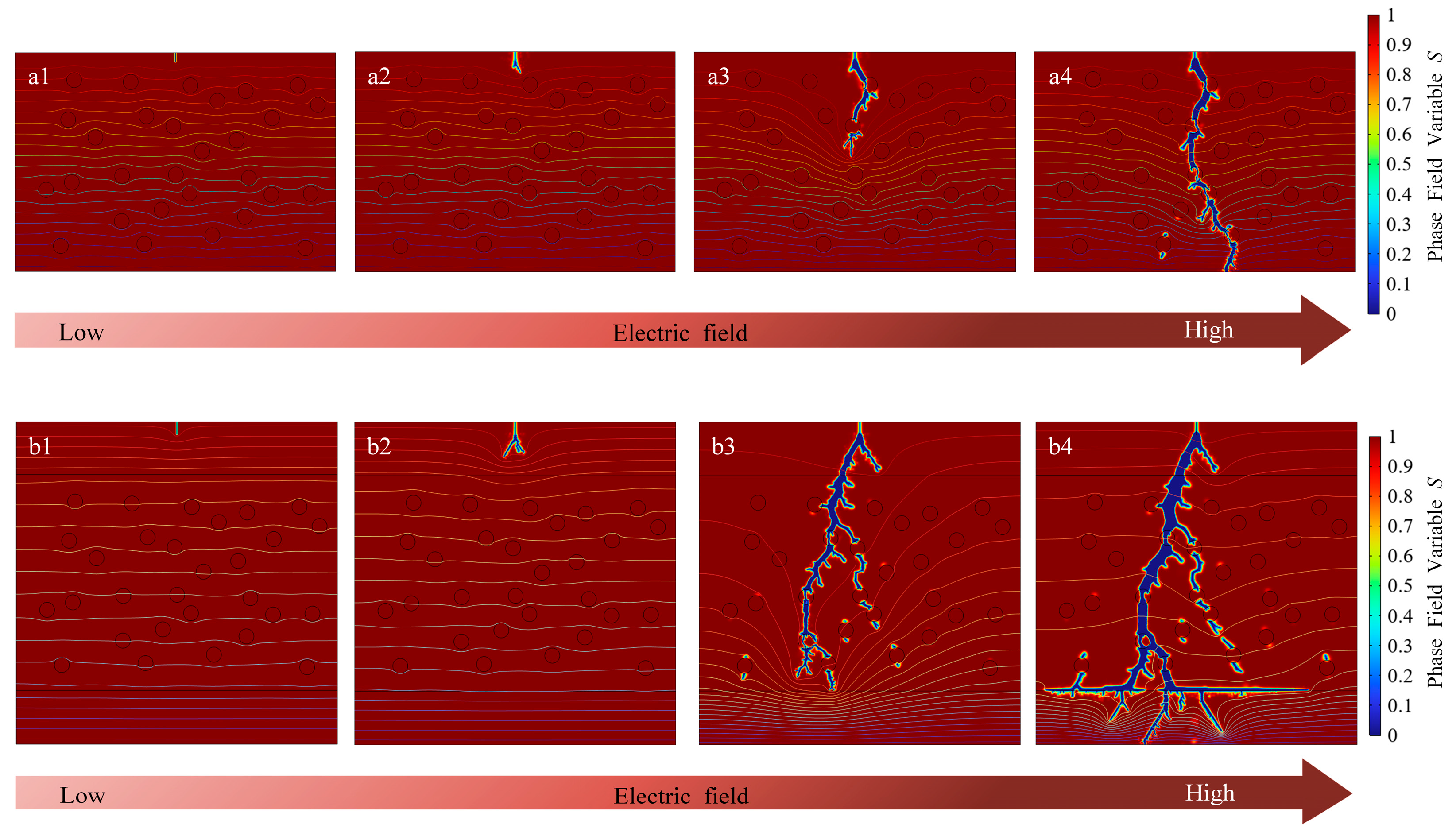
Furthermore, Equations (6) and (7) were solved to visualize the breakdown path of the composite material. In the phase field model, the top was set as a high-voltage electrode, the bottom was grounded, and a longitudinal electric field was applied. A conductor was introduced at the top of the simulation area as a field concentrator, so that the electric field was concentrated here, thereby controlling the starting position of the breakdown [29]. The development process of the internal breakdown path of single-layer 7.5 wt% BT films is shown in Figure 6(a1–a4), and the horizontal line is the real-time equipotential line. As shown in Figure 6(a1), films remained intact when the electric field strength was low. Then, as the electric field strength increased, the conductive channel began to grow from the set electric field concentrator and produced some branches, as shown in Figure 6(a2). After that, the breakdown channel continued to develop. Since the electric field at the tip of the channel was much higher than that at other positions, the development of the entire breakdown process was dominated by the tip, as shown in Figure 6(a3). Finally, as shown in Figure 6(a4), the breakdown path continued to develop toward the ground electrode, forming a conductive channel throughout the entire region inside the material. At this time, the nanocomposite was completely broken down and the insulation performance was completely lost.
The development process of the internal breakdown path of BN-7.5-BN films is shown in Figure 6(b1–b4) and was similar to the breakdown development process of 7.5 wt% BT films. However, the development of the breakdown path of the two was quite different. In the 7.5 wt% BT films with a single-layer structure, the breakdown paths were relatively concentrated, with fewer branches. In the BN-7.5-BN films with the sandwich structure, the breakdown path was tortuous and many branches were formed. Because the phase field model is always based on the criterion of phase transition to reduce total free energy, branching and tortuous breakdown paths are beneficial to dissipate more energy, thus helping to improve the breakdown strength of the composite [30]. In addition, it can be seen in Figure 6(b4) that when the breakdown path developed from the middle layer to the bottom layer, many new path branches were derived at the interface, forming an interface that effectively dissipated energy, so its breakdown field strength was higher than that of the single-layer structure. The breakdown behavior caused by electrostatic stimulation was accurately analyzed by the phase field model. It was found that the breakdown paths of 7.5 wt% BT and BN-7.5-BN were significantly different, which explains why the latter exhibited a higher Eb and was consistent with the experimental results presented in this paper.
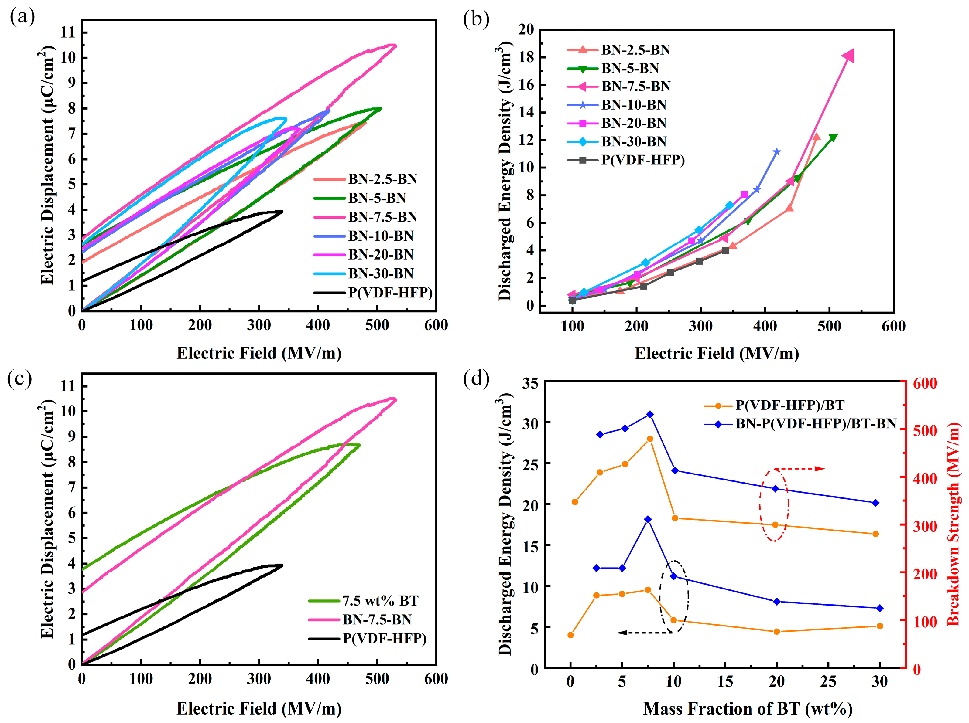
The energy density Ue of BN-P(VDF-HFP)/BT-BN nanocomposite is closely related to the D-E ferroelectric hysteresis loop, which is positively correlated with the electric field and the maximum electric displacement Dmax. Figure 7a shows the D-E loops of the BN-P(VDF-HFP)/BT-BN films with different BT NPs filling amounts. It can be seen that under the same electric field, the electric displacement increased with the increase in BT NP content. The maximum electric displacement of the films initially increased and then decreased with the increase in BT NP content, and the maximum electric displacement was achieved near the breakdown strength. When the BN-7.5-BN composite was at 530 MV/m, the maximum electric displacement of 10.5 μC/cm2 was obtained. This was due to the introduction of BN layers and the precise control of BT NP content. Based on the D-E loops, the energy density Ue of the pure P(VDF-HFP) polymer and the BN-P(VDF-HFP)/BT-BN films was calculated and is presented in Figure 7b. The Ue values of the BN-P(VDF-HFP)/BT-BN films with BT contents of 2.5 wt%, 5 wt%, 7.5 wt%, 10 wt%, 20 wt%, 30 wt%, and pure P(VDF-HFP) were 12.19, 12.22, 18.12, 11.15, 8.07, and 7.28 J/cm3, respectively. It can be seen that the sandwich-structured BN-7.5-BN nanocomposite obtained the best energy density of 18.12 J/cm3, which is about 2.5 times that of pure P(VDF-HFP).
Figure 7c displays the D-E loops near the breakdown strength of the pure P(VDF-HFP), 7.5 wt% BT, and BN-7.5-BN films. The Dmax values were 3.94 μC/cm2, 8.68 μC/cm2, and 10.5 μC/cm2. Compared with pure P(VDF-HFP), the maximum electric displacement of the 7.5 wt% BT nanocomposite was higher, mainly due to the increased dielectric constant when BT NPs were added. Further comparison revealed that the maximum electric displacement of the BN-7.5-BN nanocomposite was higher than that of the 7.5 wt% BT nanocomposite, and the D-E hysteresis loop became thinner, which helped improve the energy density of the films. Generally, higher breakdown strength leads to higher displacement of the films. In comparison with that of single-layer films, the significantly enhanced maximum displacement of the sandwich-structured BN-P(VDF-HFP)/BT-BN films mainly resulted from the increased breakdown strength, which was caused by BN-coating outer layers. The energy density and breakdown strength of the P(VDF-HFP)/BT and BN-P(VDF-HFP)/BT-BN films are compared in Figure 7d. These results demonstrate that BN layers beneficially improved the insulation and the energy storage performance of P(VDF-HFP) films.

4. Conclusions

In conclusion, BN-P(VDF-HFP)/BT-BN films with a sandwich structure were prepared by a low-cost and straightforward dip-coating method, and their properties were tested and discussed. The composite material benefits from the high insulation properties of BN and the high εr of BT NPs, allowing for the achievement of extremely high Eb and Ue. It is worth noting that the introduction of BT NPs will affect the polarization behavior and electric field distribution; therefore, it is essential to accurately control their content to optimize the comprehensive properties of P(VDF-HFP)-based films. We systematically studied the dielectric constant, loss tangent, Eb, D-E loops, and Ue of films with different BT NPs contents. The results demonstrate that the sandwich-structured BN-P(VDF-HFP)/BT-BN films filled with 7.5 wt.% BT NPs obtained 530 MV/m Eb and 18.12 J/cm3 Ue at the same time, and the loss tangent was also at a low level. Based on this, we employed the finite element method to simulate the electric field, leakage current density distribution, and breakdown evolution process within single-layer and sandwich-structured films. Through comparative studies, it was found that the BN coating had a positive effect on regulating the electric field, weakening the local high conductivity region formed by the addition of BT NPs, and introducing an energy dissipation interface, which significantly hindered the development of breakdown channels in the films. This work presents a novel design concept for thin-film capacitors, offering excellent energy storage performance.

Author Contributions

This paper is the result of a collaboration between all co-authors. Formal analysis, Y.C.; investigation, Y.C. and W.W.; methodology, Y.C. and X.B.; validation, R.G., Y.C. and Z.L. (Zhenyu Lu); data curation, Y.C., R.W. and Z.L. (Zhipeng Lei); writing—original draft preparation, Y.C. and Z.L. (Zhipeng Lei).; writing—review and editing, R.G. and W.W.; visualization, Y.C. and Y.X.; funding acquisition, W.W. All authors have read and agreed to the published version of the manuscript.

Funding

This work was supported in part by the Science and Technology Project of State Grid Shanxi Electric Power Co., Ltd. under grants 52053024000U and 5205S124001.

Data Availability Statement

The original contributions presented in this study are included in the article. Further inquiries can be directed to the corresponding author.

Conflicts of Interest

The authors declare no conflicts of interest.

References

  1. Zhou, L.; Zhao, S.; Xie, P.; Miao, X.; Liu, S.J.; Sun, N.N.; Guo, M.F.; Xu, Z.Q.; Zhong, T.J.; Shen, Y. Research progress and prospect of polymer dielectrics. Appl. Phys. Rev. 2023, 10, 031310. [Google Scholar] [CrossRef]
  2. Guo, Y.; Zhou, D.; Xu, R.; Zhu, Q.S.; Li, D.; Zhao, W.C.; Pang, L.X.; Wang, Y.F.; Liu, W.F.; Su, J.Z.; et al. Enhancement in the energy storage performance of P(VDF-HFP)-based composites by adding PLZST inorganic nanoparticles. J. Mater. Chem. A 2022, 10, 22058–22066. [Google Scholar] [CrossRef]
  3. Li, Q.; Chen, L.; Gadinski, M.R.; Zhang, S.H.; Zhang, G.Z.; Li, H.Y.; Iagodkine, E.; Haque, A.; Chen, L.-Q.; Jackson, T.N.; et al. Flexible high-temperature dielectric materials from polymer nanocomposites. Nature 2015, 523, 576–579. [Google Scholar] [CrossRef]
  4. Cheng, R.; Wang, Y.F.; Men, R.J.; Lei, Z.P.; Song, J.C.; Li, Y.Y.; Guo, M.Q. High-energy-density polymer dielectrics via compositional and structural tailoring for electrical energy storage. iScience 2022, 25, 104837. [Google Scholar] [CrossRef]
  5. Chen, J.; Wang, Y.F.; Xu, X.W.; Yuan, Q.B.; Niu, Y.J.; Wang, Q.; Wang, H. Ultrahigh discharge efficiency and energy density achieved at low electric fields in sandwich-structured polymer films containing dielectric elastomers. J. Mater. Chem. A Mater. 2019, 7, 3729–3736. [Google Scholar] [CrossRef]
  6. Zhang, M.; Li, B.; Wang, J.J.; Huang, H.B.; Zhang, L.; Chen, L.Q. Polymer dielectrics with simultaneous ultrahigh energy density and low loss. Adv. Mater. 2021, 33, 2008198. [Google Scholar] [CrossRef]
  7. Liu, G.; Zhang, T.D.; Feng, Y.; Zhang, Y.Q.; Zhang, C.H.; Zhang, Y.; Wang, X.B.; Chi, Q.G.; Chen, Q.G.; Lei, Q.Q. Sandwich-structured polymers with electrospun boron nitrides layers as high-temperature energy storage dielectrics. Chem. Eng. J. 2020, 389, 124443. [Google Scholar] [CrossRef]
  8. Wang, S.J.; Luo, Z.; Liang, J.J.; Hu, J.; Jiang, N.S.; He, J.L.; Li, Q. Polymer nanocomposite dielectrics: Understanding the matrix/particle interface. ACS Nano 2022, 16, 13612–13656. [Google Scholar] [CrossRef] [PubMed]
  9. Chen, C.; Xie, Y.C.; Liu, J.J.; Li, J.; Wei, X.Y.; Zhang, Z.Z. Enhanced energy storage capability of P(VDF-HFP) nanodielectrics by HfO2 passivation layer: Preparation, performance and simulation. Compos. Sci. Technol. 2020, 188, 107968. [Google Scholar] [CrossRef]
  10. Bao, Z.W.; Hou, C.M.; Shen, Z.H.; Sun, H.Y.; Zhang, G.Q.; Luo, Z.; Dai, Z.Z.; Wang, C.M.; Chen, X.W.; Li, L.B.; et al. Negatively charged nanosheets significantly enhance the energy-storage capability of polymer-based nanocomposites. Adv. Mater. 2020, 32, 1907227. [Google Scholar] [CrossRef]
  11. Jung, H.B.; Kim, J.W.; Lim, J.H.; Kwon, D.K.; Choi, D.H.; Jeong, D.Y. Energy Storage Properties of Blended Polymer Films with Normal Ferroelectric P(VDF-HFP) and Relaxor Ferroelectric P(VDF-TrFE-CFE). Electron. Mater. Lett. 2020, 16, 47–54. [Google Scholar] [CrossRef]
  12. Yang, C.; Hong, H.S.; Liu, D.B. Effect of coupling agents on the dielectric properties of CaCu3Ti4O12/PVDF composites. Compos. Part. B Eng. 2013, 50, 180–186. [Google Scholar] [CrossRef]
  13. Li, Y.S.; Chen, S.; Hu, J.; He, J.L.; Li, Q. Polymer nanocomposites with high energy density utilizing oriented nanosheets and high-dielectric-constant nanoparticles. Materials 2021, 14, 4780. [Google Scholar] [CrossRef]
  14. Tsyganov, A.; Vikulova, M.; Artyukhov, D.; Bainyashev, A.; Goffman, V.; Gorokhovsky, A.; Gorshkov, N. Carbon Modification of K1.6Fe1.6Ti6.4O16 Nanoparticles to Optimize the Dielectric Properties of PTFE-Based Composites. Polymers 2022, 14, 4010. [Google Scholar] [CrossRef]
  15. Wang, Y.F.; Wang, L.X.; Yuan, Q.B.; Chen, J.; Niu, Y.J.; Xu, X.W.; Chen, Y.T.; Yao, B.; Wang, Q.; Wang, H. Ultrahigh energy density and greatly enhanced discharged efficiency of sandwich-structured polymer nanocomposites with optimized spatial organization. Nano Energy 2018, 44, 364–370. [Google Scholar] [CrossRef]
  16. Wang, J.; Xie, Y.C.; Liu, J.J.; Zhang, Z.C.; Zhuang, Q.; Kong, J. Improved energy storage performance of linear dielectric polymer nanodielectrics with polydopamine coated BN nanosheets. Polymers 2018, 10, 1349. [Google Scholar] [CrossRef]
  17. Wang, Y.F.; Li, Z.Z.; Wu, C.; Cao, Y. High-temperature dielectric polymer nanocomposites with interposed montmorillonite nanosheets. Chem. Eng. J. 2020, 401, 126093. [Google Scholar] [CrossRef]
  18. Zhang, T.D.; Yang, L.Y.; Ruan, J.Y.; Zhang, C.H.; Chi, Q.G. Improved high-temperature energy storage performance of PEI dielectric films by introducing a SiO2 insulating layer. Macromol. Mater. Eng. 2021, 306, 2100514. [Google Scholar] [CrossRef]
  19. Zhang, T.D.; Yang, L.Y.; Zhang, C.H.; Feng, Y.; Wang, J.; Shen, Z.H.; Chen, Q.G.; Lei, Q.Q.; Chi, Q.G. Polymer dielectric films exhibiting superior high-temperature capacitive performance by utilizing an inorganic insulation interlayer. J. Mater. Chem. C 2022, 9, 1273–1282. [Google Scholar] [CrossRef] [PubMed]
  20. Cai, Z.M.; Wang, X.H.; Luo, B.C.; Zhao, P.Y.; Zhu, C.Q.; Li, L.T. Laminated structure-induced high dielectric strength and energy storage density in dielectric composites. Compos. Sci. Technol. 2019, 173, 61–65. [Google Scholar] [CrossRef]
  21. Marwat, M.A.; Ma, W.G.; Fan, P.Y.; Elahi, H.; Samart, C.; Nan, B.; Tan, H.; Salamon, D.; Ye, B.H.; Zhang, H.B. Ultrahigh energy density and thermal stability in sandwich-structured nanocomposites with dopamine@Ag@BaTiO3. Energy Storage Mater. 2020, 31, 492–504. [Google Scholar] [CrossRef]
  22. Park, G.H.; Nielsch, K.; Thomas, A. 2D transition metal dichalcogenide thin films obtained by chemical gas phase deposition techniques. Adv. Mater. Interfaces 2018, 6, 1800688. [Google Scholar] [CrossRef]
  23. Azizi, A.; Gadinski, M.; Li, Q.; ALSaud, M.A.; Wang, J.J.; Wang, Y.; Wang, B.; Liu, F.H.; Chen, L.Q.; Alem, N.; et al. High-performance polymers sandwiched with chemical vapor deposited hexagonal boron nitrides as scalable high-temperature dielectric materials. Adv. Mater. 2017, 29, 1701864. [Google Scholar] [CrossRef]
  24. Cai, Z.M.; Wang, X.H.; Li, L.T.; Hong, W. Electrical treeing: A phase-field model. Extreme Mech. Lett. 2019, 28, 87–95. [Google Scholar] [CrossRef]
  25. Hong, W.; Pitike, K.C. Modeling breakdown-resistant composite dielectrics. Procedia IUTAM 2015, 12, 73–82. [Google Scholar] [CrossRef]
  26. Zhang, Y.; Zhang, T.D.; Liu, L.Z.; Chi, Q.G.; Zhang, C.H.; Chen, Q.G.; Cui, Y.; Wang, X.; Lei, Q.Q. Sandwich-structured PVDF-based composite incorporated with hybrid Fe3O4@BN nanosheets for excellent dielectric properties and energy storage performance. J. Phys. Chem. C 2018, 122, 1500–1512. [Google Scholar] [CrossRef]
  27. Dissado, L.A. Understanding electrical trees in solids: From experiment to theory. In Proceedings of the 2001 IEEE 7th International Conference on Solid Dielectrics, Eindhoven, The Netherlands, 25–29 June 2001; pp. 15–26. [Google Scholar]
  28. Wang, Y.F.; Cui, J.; Wang, L.X.; Yuan, Q.B.; Niu, Y.J.; Chen, J.; Wang, Q.; Wang, H. Compositional tailoring effect on electric field distribution for significantly enhanced breakdown strength and restrained conductive loss in sandwich-structured ceramic/polymer nanocomposites. J. Mater. Chem. A 2017, 5, 4710–4718. [Google Scholar] [CrossRef]
  29. Cai, Z.M.; Wang, X.H.; Luo, B.C.; Hong, W.; Wu, L.W.; Li, L.T. Dielectric response and breakdown behavior of polymer-ceramic nanocomposites: The effect of nanoparticle distribution. Compos. Sci. Technol. 2017, 145, 105–113. [Google Scholar] [CrossRef]
  30. Zhu, M.X.; Li, J.C.; Song, H.G.; Chen, J.M. A phase field model for the propagation of electrical tree in nanocomposites. IEEE Trans. Dielectr. Electr. Insul. 2020, 27, 336–342. [Google Scholar] [CrossRef]
Figure 1. Schematic diagram for the preparation of BN-P(VDF-HFP)/BT-BN films.
Processes 13 03295 g001
Figure 2. (a) SEM images of P(VDF-HFP)/BT films with different contents of BT; (b) cross-section view; (c) surface microstructure of the BN-BT/P(VDF-HFP)-BN nanocomposite.
Processes 13 03295 g002
Figure 3. (a) XRD patterns of BN, BT, pure P(VDF-HFP), P(VDF-HFP)/BT film, and BN-P(VDF-HFP)/BT-BN film. Frequency dependence of (b) dielectric constant and (c) loss tangent of P(VDF-HFP) and BN-P(VDF-HFP)/BT-BN films at 30 °C. (d) Dielectric constant and loss tangent P(VDF-HFP)/BT and BN-P(VDF-HFP)/BT-BN films with different contents of BT.
Processes 13 03295 g003
Figure 4. Weibull distributions of (a) P(VDF-HFP)/BT and (b) BN-P(VDF-HFP)/BT-BN films; (c) breakdown strength and (d) shape parameter of P(VDF-HFP)/BT and BN-P(VDF-HFP)/BT-BN films.
Processes 13 03295 g004
Figure 5. (a,d) Electric potential, (b,e) electric field, and (c,f) leakage current density of 7.5 wt% P(VDF-HFP)/BT and BN-7.5-BN film.
Processes 13 03295 g005
Figure 6. Simulation of breakdown process for (a1a4) 7.5 wt% BT films and (b1b4) BN-7.5-BN films.
Processes 13 03295 g006
Figure 7. (a) D-E loops and (b) energy density of the P(VDF-HFP) and BN-P(VDF-HFP)/BT-BN films. (c) D-E loops of P(VDF-HFP), 7.5 wt% P(VDF-HFP)/BT, and BN-7.5-BN films. (d) Energy density and breakdown strength of P(VDF-HFP), P(VDF-HFP)/BT, and BN-P(VDF-HFP)/BT-BN films.
Processes 13 03295 g007
Disclaimer/Publisher’s Note: The statements, opinions and data contained in all publications are solely those of the individual author(s) and contributor(s) and not of MDPI and/or the editor(s). MDPI and/or the editor(s) disclaim responsibility for any injury to people or property resulting from any ideas, methods, instructions or products referred to in the content.