Article

Application of Hybrid SMA (Slime Mould Algorithm)-Fuzzy PID Control in Hip Joint Trajectory Tracking of Lower-Limb Exoskeletons in Multi-Terrain Environments

1
College of Mechanical and Vehicle Engineering, Changchun University, Changchun 130022, China
2
Key Laboratory of Intelligent Rehabilitation and Barrier-Free for the Disabled (Ministry of Education), Changchun 130022, China
3
Sellaffeld, Cumbria CA20 1DT, UK
4
Shandong Jite Industrial Technology Co., Ltd., Rizhao 276800, China
*
Author to whom correspondence should be addressed.
Processes 2025, 13(10), 3250; https://doi.org/10.3390/pr13103250
Submission received: 9 September 2025 / Revised: 7 October 2025 / Accepted: 11 October 2025 / Published: 13 October 2025
(This article belongs to the Special Issue Design and Control of Complex and Intelligent Systems)

Abstract

This paper addresses the challenges of inadequate trajectory tracking accuracy and limited parameter adaptability encountered by hip joints in lower-limb exoskeletons operating across multi-terrain environments. To mitigate these issues, we propose a hybrid control strategy that synergistically combines the slime mould algorithm (SMA) with fuzzy PID control, thereby improving the trajectory tracking performance in such diverse conditions. Initially, we established a dynamic model of the hip joint in the sagittal plane utilizing the Lagrange method, which elucidates the underlying motion mechanisms involved. Subsequently, we designed a fuzzy PID controller that facilitates dynamic parameter adjustment. The integration of the slime mould algorithm (SMA) allows for the optimization of both the quantization factor and the proportional factor of the fuzzy PID controller, culminating in the development of a hybrid control framework that significantly enhances parameter adaptability. Ultimately, we performed a comparative analysis of this hybrid control strategy against conventional PID, fuzzy PID, and PSO-fuzzy PID controls through MATLABR2023b/Simulink simulations as well as experimental tests across a range of multi-terrain scenarios including flat ground, inclines, and stair climbing. The results indicate that in comparison to PID, fuzzy PID, and PSO-fuzzy PID controls, our proposed strategy significantly reduced the adjustment time by 15.06% to 61.9% and minimized the maximum error by 39.44% to 72.81% across various terrains including flat ground, slope navigation, and stair climbing scenarios. Additionally, it lowered the steady-state error ranges by an impressive 50.67% to 90.75%. This enhancement markedly improved the system’s response speed, tracking accuracy, and stability, thereby offering a robust solution for the practical application of lower-limb exoskeletons.

1. Introduction

With the aging population and an increasing demand for rehabilitation medicine, lower-limb exoskeleton robots [1,2,3] have become a pivotal technology for facilitating assisted movement. These devices exhibit considerable value in applications such as elderly care, disability assistance, rehabilitation training, and military enhancement. The hip joint [4,5], serving as the primary power source for lower-limb movement in the human body, significantly affects the coordination between the exoskeleton system and the wearer through its precision of movement. Notably, during the human walking gait cycle, the hip joint serves as the primary contributor to the total propulsive force, playing a dominant role in lower-limb dynamics [6]. Excessive deviations from the intended movement trajectory can result in elevated energy expenditure during gait and may contribute to compensatory injuries. Within the realm of rehabilitation medicine, the accurate tracking of hip joint trajectories is essential to prevent the entrenchment of abnormal gait patterns and facilitate the restoration of neuromuscular control. For instance, Arhos et al. [7] enhanced hip joint movement trajectories through task-specific training, yielding improved knee-hip joint coordination patterns in patients with patellofemoral pain, thus indirectly bolstering the relevance of trajectory tracking for neuromuscular control restoration. Nonetheless, human gait is characterized by its highly nonlinear and time-varying nature. Consequently, exoskeletons must confront several challenges in practical applications including the system’s inherent high nonlinearity and time-varying characteristics as well as variations among individual wearers, external environmental disturbances, and fluctuations in dynamic load conditions. These challenges impose stringent requirements on the control of hip joint trajectory tracking. Therefore, the development of effective trajectory tracking control methods [8,9,10,11], tailored to meet the rehabilitation training needs of patients with lower limb movement disorders, is of considerable research significance.
Presently, both domestic and international researchers have made notable advancements in the study of control strategies for lower-limb exoskeletons. For instance, the literature [12] has employed sliding mode control for the trajectory tracking of a dual-joint manipulator, resulting in some improvement in tracking accuracy; however, this controller is complex and poses challenges in parameter determination. In a noteworthy contribution, Mou Ruiqiang [13] innovatively refined the approach law in the LLER sliding mode controller, which significantly enhanced the accuracy, albeit at the expense of inducing oscillatory phenomena. Jyotindra [14] integrated fuzzy control and neural network technologies with traditional PID control to implement passive gait rehabilitation for lower-limb exoskeleton systems. While this approach demonstrated the system’s stability and resistance to interference, it lacked empirical results from actual human testing. Xing Wenqi [15] combined sliding mode control with proportional-derivative (PD) control to enhance system control accuracy; however, the substantial computational load required to attain this accuracy hindered the system response times, thereby limiting its practical applicability. The advent of fuzzy control theory [16] has introduced a novel paradigm for tackling complex control issues within systems. By incorporating linguistic variables and fuzzy inference mechanisms, expert knowledge can be transmuted into quantifiable rule bases, facilitating effective control even in the presence of model uncertainties. This capability has been harnessed in research focusing on trajectory tracking control for lower-limb exoskeletons. Babak [17] proposed a robust adaptive neural network control framework for rehabilitation robots, utilizing fuzzy systems to construct impedance models that facilitate stable position and force control. However, the efficacy of this control strategy across multiple scenarios remains unverified, thereby restricting its broader applicability. Yin Mengke et al. [18] implemented fuzzy adaptive PID control to enhance the joint torque tracking performance, resulting in smoother assistance tailored to various wearers. Xu Yiming [19] introduced a non-singular fast terminal sliding surface control strategy, leveraging a fuzzy expanded state observer to improve the tracking accuracy in lower-limb exoskeleton systems while minimizing sliding surface vibration phenomena. Kang et al. [20] proposed a control approach for multi-pose lower-limb rehabilitation robots, integrating human–machine coupling with fuzzy PID control. This method utilizes fuzzy PID controllers to manage multi-pose rehabilitation training, effectively achieving satisfactory joint angle control. While these fuzzy control methods have improved exoskeleton control performance, their reliance on expert experience and the need for higher trajectory tracking accuracy in multi-terrain scenarios highlight the need for further optimization. To address these gaps, biomimetic intelligent algorithms have been introduced to enhance the adaptability of control systems.
In recent years, numerous researchers have turned to biomimetic intelligent algorithms in the realm of robotics. Reference [21] introduced a particle swarm optimization algorithm grounded in the exponential arrival law, which effectively reduced tracking errors in rehabilitation exercises for upper-limb exoskeleton robots. Reference [22] optimized the parameters of an omnidirectional mobile robot chassis (OMRC) control system by combining LADRC and PID with an enhanced fruit fly optimization algorithm (Le-OFFO), significantly improving the effectiveness and robustness of its trajectory tracking. Reference [23] presented an optimization method based on the cuckoo algorithm for fast continuous nonsingular terminal sliding surface control strategies, validating its effectiveness through trajectory tracking experiments on industrial robots. These studies affirm the applicability of intelligent optimization algorithms in complex system control and open up new avenues for research in trajectory tracking for lower-limb exoskeleton robots. The slime mould algorithm (SMA), proposed by Li et al. [24], has garnered considerable attention due to its distinctive adaptive topological structure and multi-modal search mechanism. In comparison to conventional swarm intelligence algorithms, the SMA maintains a dynamic equilibrium between global exploration and local exploitation by mimicking the adaptive network formed by slime moulds during their foraging behavior. This feature provides significant advantages in tackling parameter optimization challenges in nonlinear systems operating across multi-terrain environments. Consequently, optimizing hybrid control systems through intelligent optimization algorithms allows for the retention of the stability inherent in traditional methods while fully utilizing the effective integration of fuzzy control with expert knowledge and enhancing environmental adaptability. This approach provides a viable solution for improving the responsiveness and accuracy of trajectory tracking control in lower-limb exoskeletons.
This study aims to bridge the research gap in adaptive control for lower-limb exoskeletons by proposing a novel hybrid control strategy that synergistically combines the slime mould algorithm (SMA) with a fuzzy PID controller. The primary objective of this work was to enhance the trajectory tracking performance and dynamic responsiveness of the hip joint in multi-terrain walking environments. To achieve this goal, our research was structured around three key aspects: first, establishing a dynamic model of the hip joint to accurately characterize its motion patterns; second, developing the SMA-optimized fuzzy PID controller to achieve real-time parameter tuning and adaptive control; and finally, comprehensively validating the control strategy’s efficacy and superior performance through both simulation analysis and physical experiments. By introducing this optimized framework and providing empirical evidence of its advantages, this work contributes to the field by offering a more intelligent and robust solution for exoskeleton control, effectively addressing the challenges of trajectory tracking across varied terrains. The remainder of this paper is organized as follows. Section 2 details the formulation of the hip joint dynamic model. Section 3 presents the design of the SMA-optimized fuzzy PID controller. Section 4 and Section 5 provide the simulation and experimental validation results, respectively. Section 6 discusses these findings, and finally, Section 7 concludes the paper.

2. Kinematic Analysis of the Lower-Limb Exoskeleton Hip Joint Mechanism

Building upon the sagittal plane-dominated characteristics of lower limb movement identified in biomechanics research, this study employed the Lagrange dynamics method to develop a dynamic model of the hip joint in the sagittal plane. This model aims to elucidate the movement mechanisms of the hip joint in lower-limb exoskeletons. A simplified diagram of the proposed model is presented in Figure 1.
Define the following parameters for the lower-limb exoskeleton robot’s thigh rod: let l represent the length, m denote the mass, d signify the distance from the center of mass to the rotation center o, and I indicate the rotational inertia about the center of mass. Additionally, let θ represent the rotation angle of the hip joint, θ ˙ the angular velocity, and θ ¨ the angular acceleration of the hip joint. Finally, let τ denote the control torque at the hip joint and g represent the gravitational acceleration.
Let the coordinates of the center of mass of the thigh link be (x1, y1), then the expression for the center of mass is:
x 1 = d c o s θ y 1 = d s i n θ
The square of the velocity of the center of gravity of the thigh connecting rod is:
v c 2 = x ˙ 1 2 + y ˙ 1 2 = d 2 θ ˙ 2
Hip joint kinetic energy is:
E k = 1 2 m v c 2   + 1 2 I ω 2 = 1 2 m d 2 θ ˙ 2 + 1 2 I θ ˙ 2
The potential energy of the hip joint is:
E p = m g d s i n θ
The Lagrange function of the hip joint of the lower-limb exoskeleton robot is:
L = E k E p = 1 2 m d 2 θ ˙ 2 + 1 2 I θ ˙ 2 m g d s i n θ
The Lagrange equations of motion corresponding to the thigh link of the lower-limb exoskeleton can be expressed as follows:
τ = d d t L θ ˙ L θ = m d 2 θ ¨ + I θ ¨ + m g d c o s θ

3. Design of the Control System

3.1. Proportional-Integral-Derivative (PID) Controller

Traditional proportional-integral-derivative (PID) controllers are extensively utilized in industrial production settings due to their straightforward architecture and outstanding control performance. The control architecture is depicted in Figure 2.
In the figure, r(t) represents the desired input value, y(t) denotes the actual output value of the system, and u(t) indicates the output value of the PID controller at time t. The control law governing the system can be expressed as follows:
u ( t ) = k p e ( t ) + k i 0 t e ( t ) d t + k d d e ( t ) d t
The equation presented above is derived from classical PID control theory, where kp, ki, and kd represent the proportional, integral, and derivative coefficients of the PID controller, respectively. Additionally, e(t) signifies the error between the desired input value and the actual output value, which can be expressed as follows:
e ( t ) = r ( t ) y ( t )

3.2. Design of the Fuzzy PID Controller

In the examination of lower-limb movement assistance systems for the human body, traditional PID control methods often struggle to maintain system stability. This difficulty arises from the limitations inherent in simplified hip joint modeling as well as the uncertainties introduced by external disturbances during operation. Notably, in light of the biocompatibility requirements for human–machine collaboration during rehabilitation training, the adaptability of the control system parameters has emerged as a critical design consideration. Consequently, this study proposes a PID control system informed by fuzzy reasoning mechanisms.
As illustrated in the control system architecture depicted in Figure 3, the fuzzy inference module is responsible for monitoring deviations in system states and their characteristics of change, thereby establishing a parameter adjustment mechanism with nonlinear mapping capabilities. This approach overcomes the static gain limitations typical of traditional PID controllers by employing a three-dimensional fuzzy decision table to facilitate the coordinated optimization of the proportional coefficient, integral time, and derivative time parameters. Specifically, the system achieves dynamic regulation through three progressive stages, enhancing control performance: (1) input fuzzification based on triangular membership functions, (2) fuzzy rule inference utilizing a database of expert experiences, and (3) accurate defuzzification of output quantities through the center of gravity method.
In the figure, Sd represents the ideal trajectory of hip joint movement in the human lower limb, while s denotes the actual trajectory of hip joint movement. The variable Se represents the deviation between the ideal and actual trajectories of the hip joint movement angle, which can be expressed mathematically as:
s e = s d s
Sec represents the rate of change in the angular deviation of the hip joint movement trajectory:
s e c = d s e d t
∆kp, ∆ki, and ∆kd represent the correction parameters applied to the PID controller, which are derived through fuzzy reasoning. Accordingly, the parameters of the PID controller can be expressed as follows:
k p = k p 1 + Δ k p k i = k i 1 + Δ k i k d = k d 1 + Δ k d
In the equation, kp1, ki1, and kd1 denote the original parameters associated with each component of the PID controller, respectively. u represents the output value resulting from the synergistic effects of fuzzy control and PID control, which is expressed as follows:
u ( t ) = ( k p 1 + Δ k p ) e ( t ) + ( k i 1 + Δ k i ) 0 t e ( t ) d t + ( k d 1 + Δ k d ) d e ( t ) d t
The equation u(t) represents an extension of the PID control method integrated with fuzzy logic, specifically developed to meet the unique requirements of lower-limb exoskeleton systems. This approach delivers adaptive adjustment capabilities to address challenges associated with the control of lower-limb exoskeletons.
The fuzzy PID controller designed in this paper utilizes the hip joint angular deviation Se and the rate of change of deviation Sec as input variables, yielding outputs of ∆kp, ∆ki, and ∆kd. The fuzzy sets for both input and output variables are defined as {NB (negative large), NM (negative medium), NS (negative small), ZE (zero), PS (positive small), PM (positive medium), PB (positive large)}. The domains for the input variables Se and Sec are [−3, 3], while the domain for the output variable ∆kp is [−3, 3], ∆ki is [−1, 1], and ∆kd is [−2, 2]. The quantization factors for the input variables Se and Sec are ke and kec, respectively, and the proportional factors for the output variables ∆kp, ∆ki, and ∆kd are Ckp, Cki, and Ckd, respectively. Triangular membership functions, known for their simplicity and efficiency, are employed for the input and output variables. The specific fuzzy rules governing the relationships between these parameters are detailed in Table 1.
Figure 4 illustrates the variations in the output variables of the fuzzy PID controller.

3.3. Hybrid SMA-Fuzzy PID Control System

3.3.1. Slime Mould Algorithm

The slime mould algorithm is a swarm intelligence optimization technique that mimics the feeding process of slime moulds to achieve optimization. Its advantages include a minimal number of parameters and strong adaptability, making it suitable for various engineering problems. The feeding behavior of slime moulds involves three main stages: approaching food, surrounding food, and obtaining food.
When approaching food, slime moulds utilize airborne odors to locate food sources. This behavior of locating food can be mathematically expressed as follows:
X t + 1 = X b t + v b W X A t X B t r <   p v c X t r p
In the equation, t represents the current iteration number, X denotes the position of the slime mould, and X b t indicates the position of the individual with the highest odor concentration during the current search for food sources (i.e., the optimal position). The parameters v b and v c are oscillation parameters used to adjust the position of the individual. v b is a parameter between −a and a. The parameter v c is a value between 0 and 1 that decreases linearly from 1 to 0 with each iteration count. Additionally, w represents the weight of the slime mould, while X A and X B are two individuals randomly selected from the slime mould population. The term r is a random number within the interval [0, 1], and p is the decision parameter. When r < p, the system is characterized by a global search state, progressively converging toward the current optimal position. Conversely, when r ≥ p, the system transitions to a local search state.
The formula for calculating p is given by:
p = tanh S i D F
where i = 1, 2, 3, …, N, S(i) is the fitness value of slime mould individual X, and DF is the best fitness value of slime mould individuals in all iterations.
The permissible range for the parameter v b is defined as [−a, a], where a is expressed as follows:
a = arctan h t T + 1
where T is the maximum number of iterations.
W is expressed as:
W S I i = 1 + r log b F S i b F w F + 1 , c o n d i t i o n 1 r log b F S i b F w F + 1 , o t h e r s
S I = s o r t S
Within this context, bF and wF denote the highest and lowest fitness values achieved during the current iteration, respectively. The term ‘condition’ pertains to the upper half of S(i) within the population ranking, while SI signifies the sequence that is arranged by fitness values in ascending order, applicable to minimization problems.
The mechanism by which slime moulds surround food mimics the contraction patterns observed in their veins. As the concentration of food in proximity to the veins increases, there is a corresponding amplification in the oscillatory waves produced by the biological oscillator. This intensifies the contraction of the slime mould tubes during the foraging process, accelerates cytoplasmic flow, and increases the thickness of the veins. This unique adaptation allows slime moulds to efficiently gather the necessary nutrients. Consequently, the foraging position of the slime mould is updated as follows:
X = r a n d U B L B + L B ,   r a n d < z X b t + v b W X A t X B t ,   r < p v c X t , r p
In the given formula, rand represents a random value ranging from 0 to 1; LB and UB denote the lower and upper bounds of the search space, respectively. The parameter Z is crucial for sustaining a balance between exploration and exploitation within the algorithm. Relevant studies indicate that optimal performance is achieved when Z is set to 0.03.
During the food acquisition phase, the presence of food sources induces oscillations in the slime mould, leading to alterations in the cytoplasmic flow within its venous network, which facilitates the slime mould’s continuous movement toward the food source. The oscillation parameters v b and v c are employed to model the selection behavior exhibited by the slime mould, with v b constrained within the interval [−a, a] to help circumvent local optima. Additionally, W represents the oscillation frequency of the slime moulds in response to varying food concentrations, allowing them to swiftly approach high-concentration food sources upon detection while demonstrating a more gradual exploration strategy when encountering low-concentration food sources. This dual approach significantly enhances the slime moulds’ efficiency in locating optimal food sources.

3.3.2. Process of Establishing a Hybrid SMA-Fuzzy PID Control System

In response to the challenges posed by low regulation efficiency and prolonged convergence times, which are often attributable to an over-reliance on expert judgment in the tuning of the quantization and proportional factors within traditional fuzzy PID controllers, this study introduced a dynamic parameter optimization strategy grounded in the slime mould optimization algorithm. This approach aims to enhance the aforementioned performance metrics significantly. The slime mould algorithm (SMA), distinguished by its unique adaptive search mechanism and its robust capacity to balance global exploration with local exploitation, facilitates the dynamic optimization of control parameters. During this optimization, the search space for the parameters is constrained by the predefined domains of the fuzzy sets: the input variables ( S e , S e c ) are bounded within [ 3 , 3 ] , and the output variables ( Δ K p , Δ K i , Δ K d ) are bounded within [ 3 , 3 ] , [ 1 , 1 ] , and [ 2 , 2 ] , respectively. These bounds ensure that the optimized parameters remain within physiologically and dynamically feasible ranges. Figure 5 illustrates the flowchart of the parameter optimization algorithm employed in the hybrid SMA-fuzzy PID control framework, delineating the specific implementation steps as follows:
(1.)
Parameter Initialization and Algorithm Configuration
The population size of the slime mould is configured to 30 individuals, with a maximum iteration count set to 50, the convergence coefficient β designated as 0.8, and the oscillation control parameter z established at 0.03. A typical human gait cycle lasts approximately 1.2 s. In order to align with the dynamic characteristics of the hip joint control system and ensure data validity, the control cycle was set to 6 s.
(2.)
Fitness Function Construction
The optimization objective function is defined as the time-weighted absolute error integral criterion, expressed mathematically as follows:
J = 0 t t s e ( t ) d t
To ensure consistency in the evaluation criteria and fairness in the comparison during parameter tuning of different evolutionary algorithms (e.g., the particle swarm optimization (PSO) algorithm used for comparative analysis in this study), all evolutionary algorithms involved in the comparative experiments adopted the same time-weighted absolute error integral (ITAE) as the objective function.
In this expression, Se(t) denotes the tracking error of the hip joint angle, while t represents the operational cycle of the system. This metric serves as an effective measure for assessing the system’s dynamic response speed and steady-state accuracy.
(3.)
Joint Simulation Implementation
A collaborative simulation framework has been developed utilizing the MATLABR2023b/Simulink platform. This framework enables real-time data interaction between the SMA optimization module and the fuzzy PID control system, resulting in the output of the optimal parameter combination. The essential structure for parameter storage is delineated as follows:
optParams(iteration,:) = [Kp_opt, Ki_opt, Kd_opt, Ke_opt, Kec_opt]
fitnessHistory(iteration) = currentMinFitness
(4.)
Dynamic Optimization Process
Throughout the iterative process, the algorithm dynamically modifies the parameter space search strategy, emulating the feeding behavior of slime moulds. Each iteration meticulously records both the optimal fitness value and the associated parameters. Upon reaching the predefined iteration count, the globally optimal parameters are integrated into the control system for subsequent verification. The design of the fitness function is intended to correlate smaller fitness values with improved trajectory tracking accuracy and control stability. Consequently, the optimal parameter combination that results in the minimum fitness value signifies the best performance of the corresponding control system.

4. Simulation Analysis

4.1. Parameter Tuning of Hybrid SMA-Fuzzy PID Control System

This study explored the optimization of parameter tuning for a fuzzy PID controller, utilizing the slime mould algorithm (SMA) within the MATLAB simulation environment. In accordance with the national standard GB/T 10000-2023 [25], titled “Human Body Dimensions for Adults in China”, this research established a biomechanical model to represent hip joint movement within the lower limbs. The specific parameters pertaining to the exoskeleton were defined as follows: the mass of the thigh was designated at 0.143 kg, the length of the lower limb link was set at 0.46 m, and the rotational inertia was calculated to be 0.01 kg·m2. Regarding the configuration of the simulation environment, a fixed-step solver was employed for numerical computations, with a step size established at 0.01 s to ensure computational accuracy. Gravitational acceleration was consistently standardized at 9.81 m/s2 to maintain uniformity across simulations. The population size for the slime mould algorithm was configured to 30, with a solution dimension of 5. Correspondingly, the population size for the particles in the particle swarm optimization (PSO) algorithm was also set to 30, maintaining the same solution dimension of 5. Subsequently, the joint simulation was executed in accordance with the flowchart presented in Figure 5.
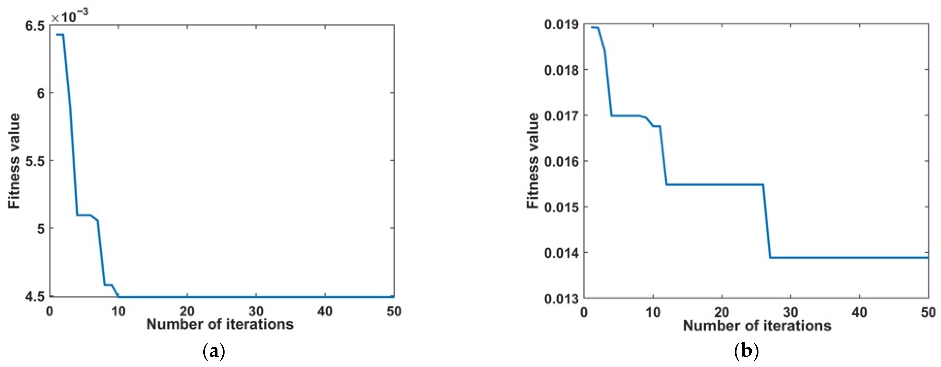
A comparative analysis of the optimal fitness convergence curves presented in Figure 6 revealed that the optimal fitness value of the lower-limb exoskeleton hip joint control system utilizing the particle swarm optimization (PSO) algorithm stabilized after 27 iterations, achieving its minimum value. Conversely, the optimal fitness value for the same control system employing the slime mould algorithm (SMA) remained constant after just 10 iterations, ultimately reaching a minimum value of 0.0045. These findings indicate that the SMA algorithm exhibits superior optimization efficiency.
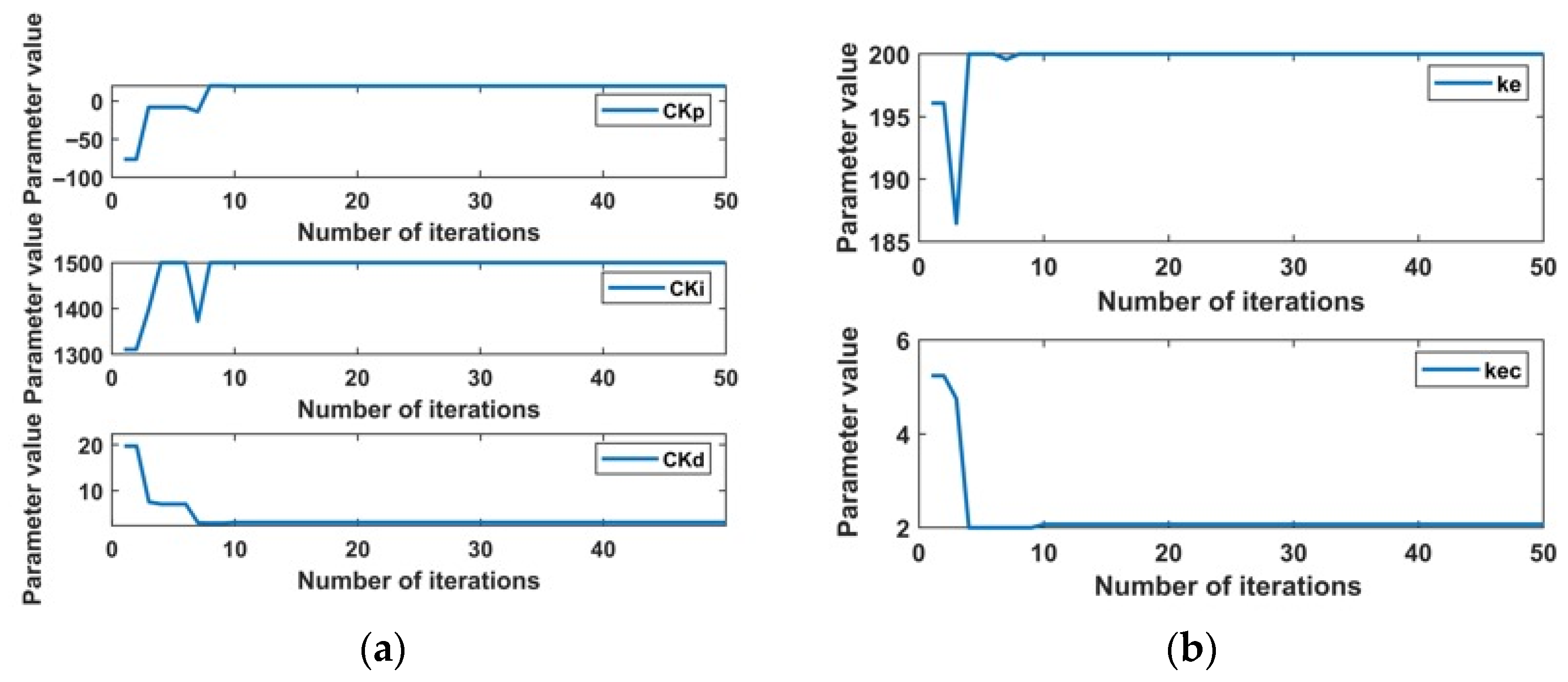
As illustrated in Figure 7, the optimal parameters determined through the slime mould algorithm (SMA) were as follows: Ke = 200, Kec = 2.0159, CKp = 10, CKi = 1500, and CKd = 0.3702.

4.2. Comparative Analysis of Trajectory Tracking Simulations for Lower-Limb Exoskeleton Hip Joint Robots Utilizing Various Control Methods Across Diverse Terrain Conditions

To assess the adaptive control performance of the hybrid SMA-fuzzy PID controller across multi-terrain environments, we performed simulation comparisons of hip joint trajectory tracking for lower-limb exoskeletons in three representative scenarios: flat ground walking, slope walking, and stair climbing. The simulations encompassed various control methodologies including PID control, fuzzy PID control, PSO-fuzzy PID control, and the hybrid SMA-fuzzy PID controller. Drawing upon the biomechanical characteristics of lower limb movement, a sine curve was selected as the reference model for the desired trajectory due to its capacity to effectively replicate the periodic characteristics of hip joint movement across varying terrains through parameter modulation. For flat ground walking, a low-frequency, high-stability sine curve was employed, which exhibited a smooth waveform devoid of pronounced fluctuations, thereby reflecting the uniformity and stability of hip joint movement in this scenario. In contrast, slope walking was modeled with a gradually varying sinusoidal signal, simulating the progressive alterations in joint angle. Stair climbing was represented by a step-modulated sinusoidal periodic signal, illustrating the phased impact characteristics associated with leg-lifting movements. The control system for the lower-limb exoskeleton hip joint, developed for the experiment, is illustrated in Figure 8.

4.2.1. Examination of Trajectory Tracking Characteristics in Flat Ground Walking Scenarios

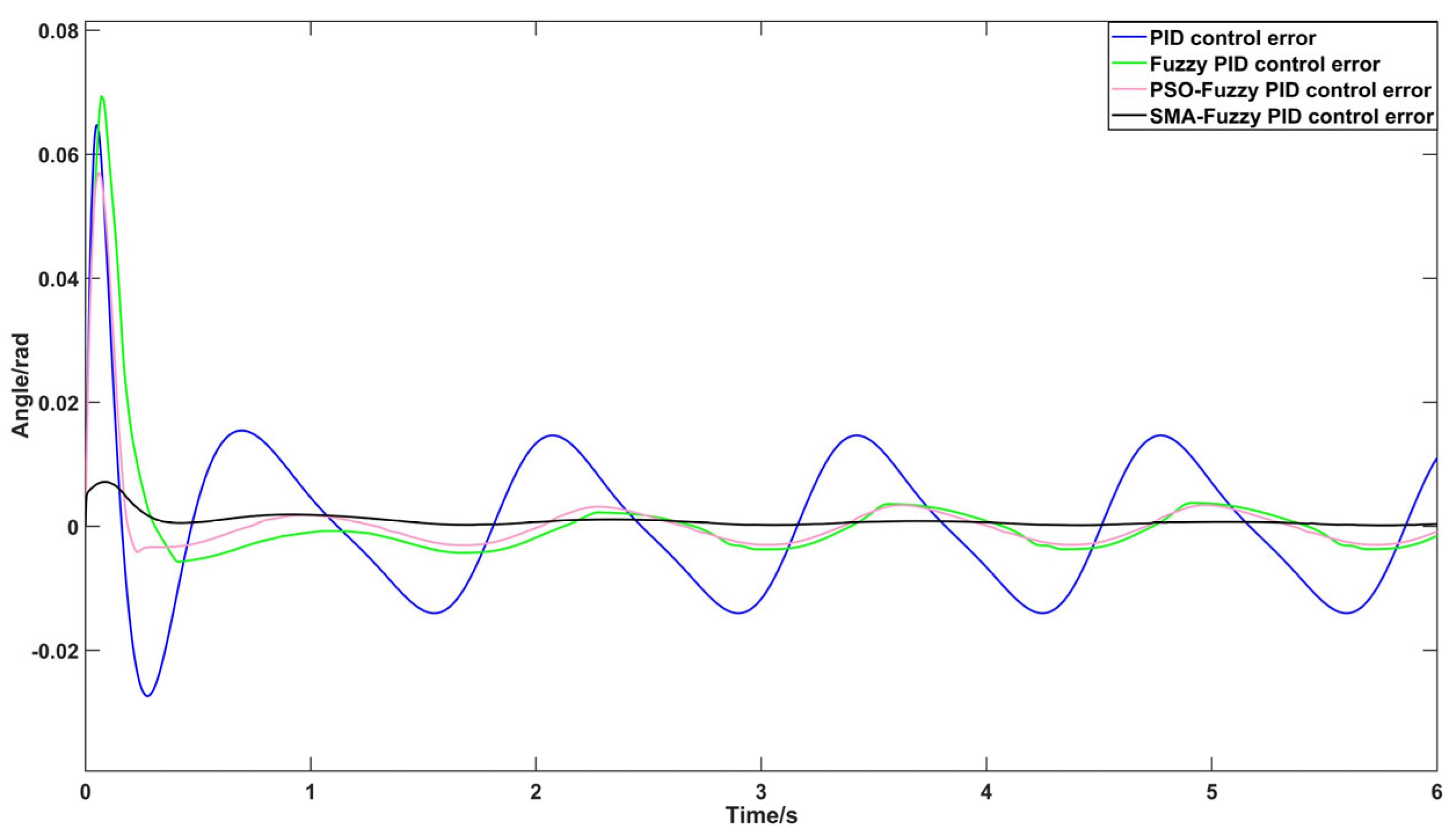
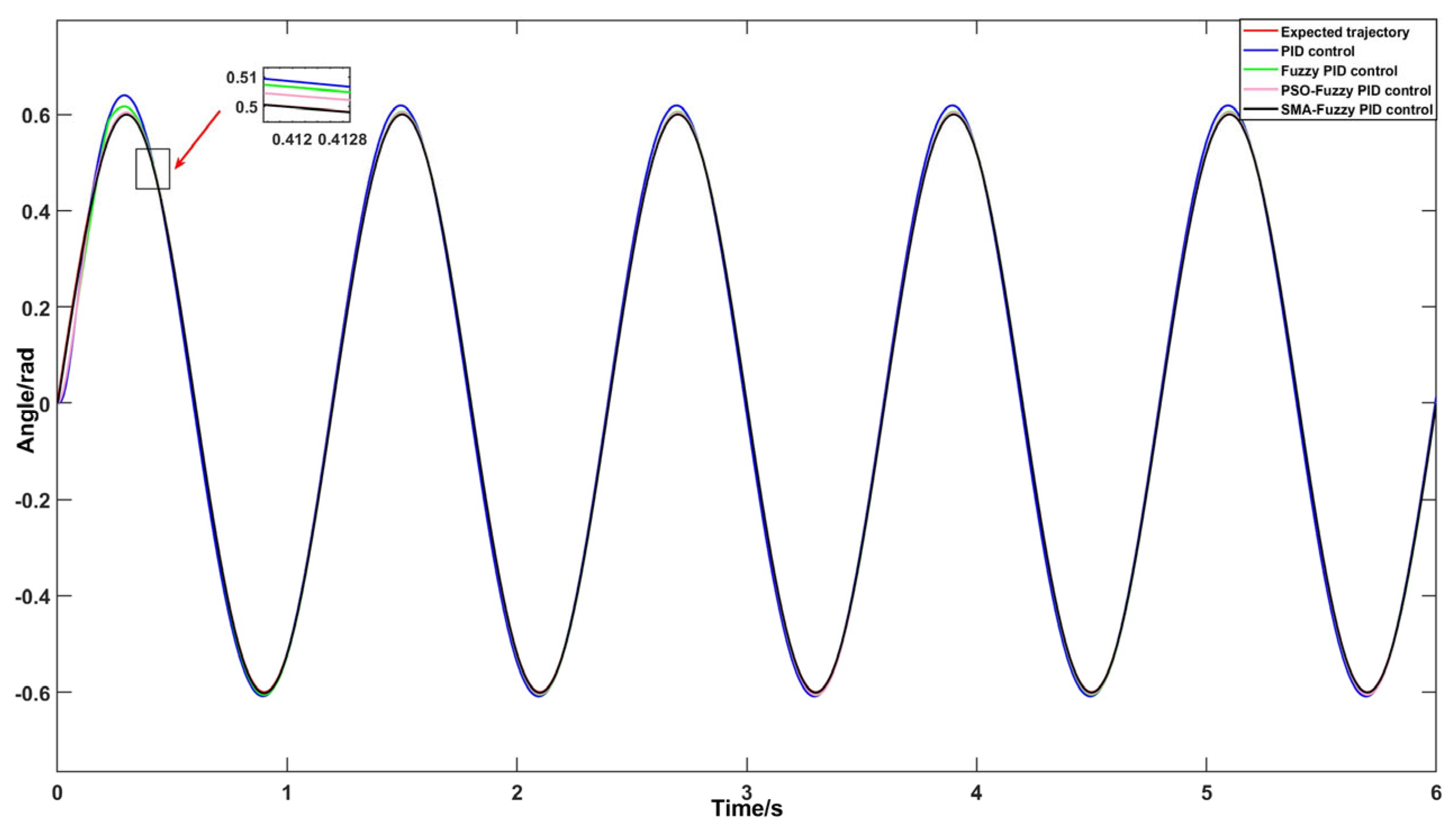
This test employed a low-frequency, high-stability sine wave signal to simulate the angular variations of the hip joint during flat ground walking. The duration of the simulation was set to 6 s, with the results presented in Figure 9 and Figure 10.
As illustrated in the trajectory tracking curve presented in Figure 9, the output trajectories generated by all controllers displayed periodic fluctuations that aligned with the gait cycle. Regarding tracking accuracy, the SMA-fuzzy PID control demonstrated superior performance, achieving the highest degree of conformity between its trajectory and the desired trajectory. Notably, it exhibited minimal deviation at critical phase points such as peaks and troughs. The PSO-fuzzy PID control came in a close second, whereas traditional PID and fuzzy PID controls showed relatively larger deviations. In terms of convergence speed, the SMA-fuzzy PID control again took the lead, reaching a stable tracking state in merely 0.362 s. This was significantly quicker than the times recorded for PSO-fuzzy PID control (0.418 s), traditional PID control (0.477 s), and fuzzy PID control (0.612 s), thereby underscoring its superior dynamic response characteristics.
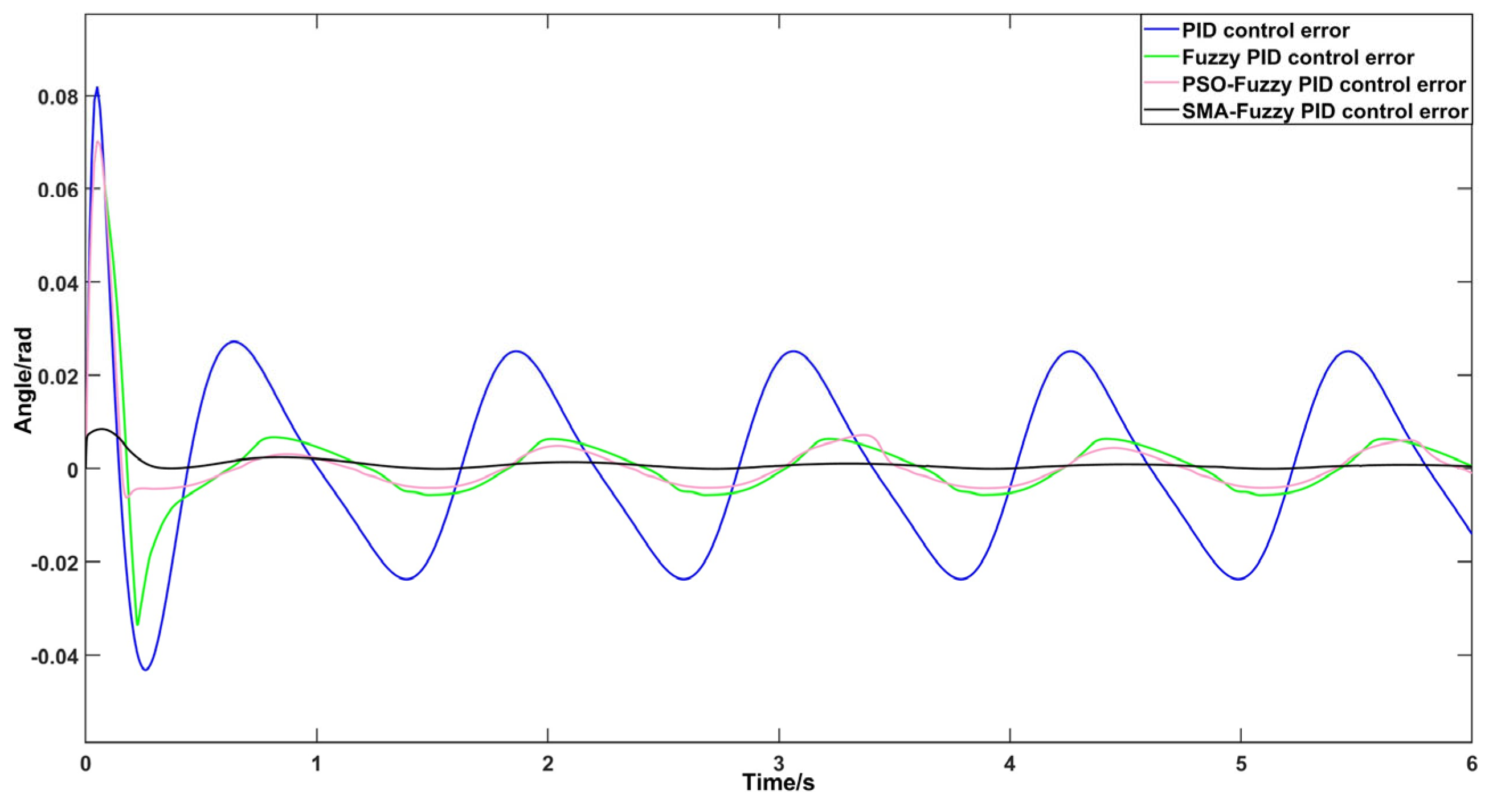
As illustrated in Figure 10, the simulation results of the tracking error curves for each controller revealed that the classical PID controller exhibited the most substantial steady-state error fluctuation range, spanning from −0.01399 rad to 0.01541 rad. This was followed by the fuzzy PID controller, with a range of −0.003682 rad to 0.003603 rad. In contrast, the PSO-fuzzy PID controller demonstrated the smallest fluctuation range, from −0.002963 rad to 0.003421 rad. Notably, the SMA-fuzzy PID controller exhibited markedly superior steady-state tracking accuracy compared with the other control methods.

4.2.2. Examination of Trajectory Tracking Characteristics in Slope Walking Scenarios

This experiment employed a gradually changing sine wave signal to emulate the angular variations of the hip joint during slope walking. The duration of the simulation was established at six seconds to encompass an entire gait cycle. The corresponding results are illustrated in Figure 11 and Figure 12.
Figure 11 presents a comparative analysis of the hip joint trajectory tracking performance across four distinct control strategies in a slope walking scenario. The results indicate that all four controllers are capable of tracking the target trajectory; however, the hybrid SMA-fuzzy PID control demonstrated a markedly superior alignment with the desired trajectory, distinguished by the minimal tracking error and the highest tracking accuracy among the tested methods. Analyzing the temporal dimension of trajectory convergence to stable tracking, the times recorded for achieving stable tracking with PID, fuzzy PID, PSO-fuzzy PID, and SMA-fuzzy PID control were 0.441 s, 0.447 s, 0.438 s, and 0.384 s, respectively. Clearly, among the four control strategies, the SMA-fuzzy PID control method exhibited the fastest convergence of the hip joint motion trajectory, effectively achieving stable tracking of the desired trajectory with remarkable dynamic response and rapid convergence speed.
The simulation results presented in Figure 12 demonstrate that the tracking errors associated with the classical PID controller, fuzzy PID controller, and PSO-fuzzy PID controller exhibited a periodic variation trend. Among these, the classical PID controller exhibited the largest range of steady-state error fluctuations, spanning from −0.02374 rad to 0.02513 rad. In contrast, the fuzzy PID controller’s steady-state error range was considerably narrower, falling between −0.005638 rad and 0.006602 rad, whereas the PSO-fuzzy PID controller demonstrated an even smaller steady-state error range of −0.004138 rad to 0.004850 rad. The tracking error associated with the hybrid SMA-fuzzy PID controller stabilized following a brief adjustment period, resulting in a steady-state error range that approached zero. These simulation results confirm that the hybrid SMA-fuzzy PID control method demonstrates superior tracking performance in accurately monitoring the hip joint movement angle during human slope walking.

4.2.3. Examination of Trajectory Tracking Characteristics in Staircase Walking Scenarios

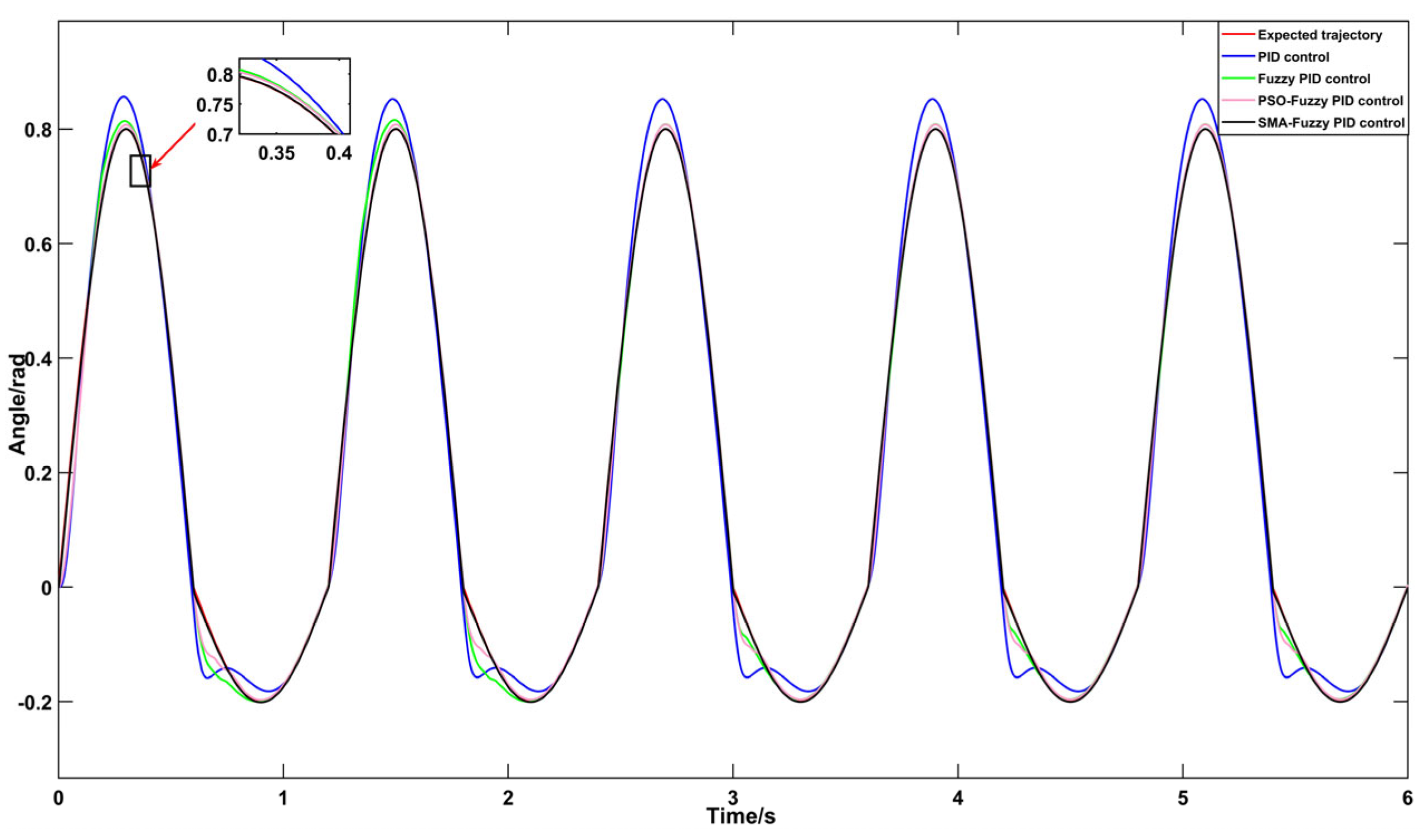
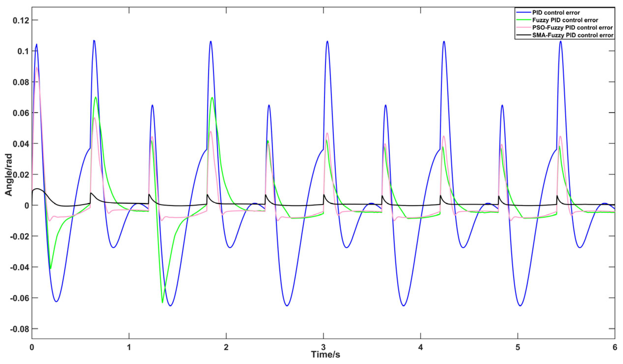
To analyze the step cycle characteristics associated with stair climbing, a segmented sine wave signal was devised, featuring an amplitude of 0.8 rad during the first half cycle and 0.2 rad during the second half cycle. This trajectory effectively simulates the abrupt angular changes occurring during the leg lift phase. The simulation was conducted over a duration of 6 s, with the resulting data illustrated in Figure 13 and Figure 14.
Figure 13 presents a comparative analysis of the hip joint trajectory tracking performance across four distinct controller types within the context of an ascending walking scenario. The findings indicate that each controller is capable of producing periodic trajectories that effectively adapt to the characteristics of human gait. Notably, the hybrid SMA-fuzzy PID control demonstrated a tracking trajectory that was highly aligned with the desired trajectory, thereby significantly surpassing the performance of the other three controller types. Regarding dynamic response, the convergence times to steady state for the four controllers were recorded as 0.438 s, 0.534 s, 0.412 s, and 0.3 s, respectively. It is evident that the hybrid SMA-fuzzy PID control achieved the quickest convergence speed among the four methodologies assessed.
The simulation results presented in Figure 13 and Figure 14 demonstrate that the hybrid SMA-fuzzy PID controller achieved the optimal performance in tracking the angle of the hip joint movement during the activity of human stair climbing. The tracking trajectory depicted in Figure 13 closely corresponded to the desired trajectory, indicating a high level of accuracy in motion tracking. The error analysis illustrated in Figure 14 revealed that the classical PID, fuzzy PID, and PSO-fuzzy PID controllers each demonstrated periodic steady-state errors, with fluctuation ranges of −0.06508 rad to 0.1057 rad, −0.008305 rad to 0.04221 rad, and −0.009864 rad to 0.04777 rad, respectively. In contrast, the hybrid SMA-fuzzy PID controller displayed a steady-state error fluctuation range of 0 to 0.006659 rad following a brief adjustment period, thereby demonstrating enhanced tracking accuracy and stability relative to the other control methods.

5. Empirical Evaluation of Trajectory Tracking in a Lower-Limb Exoskeleton Hip Joint Robot

5.1. Design of the Experimental Platform and Test Scenarios

To assess the adaptive trajectory tracking capabilities of the hybrid SMA-fuzzy PID control system within multi-terrain environments, an experimental platform was developed, as depicted in Figure 15. This experimental platform comprised a development host, a PC host computer, a signal relay and control box, an inertial measurement unit (IMU) sensor, a main controller, and a brushless DC motor. In accordance with GB 50352-2019 “Unified Standards for Civil Building Design [26]”, typical parameters representative of multi-terrain conditions were established: a slope angle of 15° was chosen for the slope scenario (reflecting common inclines encountered in everyday walking), and a step height of 15 cm was designated for the staircase scenario (aligning with standard specifications for residential and public buildings).
The experiment involved a healthy male tester, with a height of 178 cm and a weight of 83 kg. In contrast to traditional flat terrain scenarios, multi-terrain testing places greater demands on lower limb coordination. Therefore, the tester was required to successfully complete a basic balance screening test (maintaining a single-leg stance for at least 10 s [27]) prior to participating in the experiment. Considering the typical characteristics of the gait cycle (1.2 s per cycle) and adhering to clinical guidelines for spinal cord injury rehabilitation—which recommend a minimum of 8 to 12 cycles for effective training—the actual test duration was established at 12 s. This duration encompassed 10 complete gait cycles, enabling a comprehensive evaluation of the system’s stability and tracking performance throughout sustained movement. Additionally, the simulation duration was set to 6 s, covering 5 cycles, with the primary focus on verifying dynamic convergence. Together, these two durations establish a closed-loop evaluation system that effectively assesses the performance and reliability of the lower-limb exoskeleton during varied gait scenarios.
The procedure for collecting hip joint gait experimental data necessitates that test subjects don lower-limb exoskeleton hip joint devices as they walk across various terrains including flat ground, slopes, and stairs. After the hip joint gait data stabilized, the tester’s hip joint movement data were collected and recorded using an inertial measurement unit (IMU). The gathered data underwent processing through Kalman filtering and MATLAB fitting to establish the expected trajectory for the lower-limb exoskeleton hip joint robot during multi-scenario tracking tests within the experimental framework. Figure 16 depicts the procedure for collecting movement data during the tester’s use of the lower-limb exoskeleton device.
Prior to the experiment, various algorithms—including PID control, fuzzy PID control, PSO-fuzzy PID control, and hybrid SMA-fuzzy PID control—were developed in Simulink and subsequently uploaded to the hip joint controller of the lower-limb exoskeleton robot using the ST-LINK tool, ensuring optimal performance of the robotic system. Throughout the experiment, the wireless communication module installed on the exoskeleton facilitated a connection to its paired module on the PC host. This setup enabled the utilization of serial port debugging tools to collect and record real-time data on hip joint movement angles, which would later be analyzed for deeper insights and observations.

5.2. Analysis of Actual Measurement Results Across Multiple Terrain Conditions

5.2.1. Trajectory Tracking Tests of Flat Walking in Test Subjects Under Four Distinct Control Methods

Figure 17 illustrates the hip joint movement trajectories and tracking errors, respectively, of test subjects walking on flat ground using four distinct control methods. These figures intuitively highlight the variations in control performance among the methods. For a more comprehensive quantitative assessment, Table 2 presents the parameters related to the tracking process for each control system.
The experimental results presented in Figure 17, along with Table 2, indicate that the hybrid SMA-fuzzy PID control exhibits considerable advantages in flat-ground walking scenarios. When compared with traditional PID control, fuzzy PID control, and PSO-fuzzy PID control, this hybrid approach achieved a comprehensive optimization of key performance metrics: regulation time was reduced by 35.36%, 27.41%, and 15.06%, respectively; the maximum trajectory tracking error was decreased by 53.62%, 44.24%, and 39.44%, respectively; additionally, the fluctuations in steady-state error were significantly minimized, with respective improvement rates of 86.70%, 52.52%, and 50.67%. In conclusion, the hybrid SMA-fuzzy PID control greatly enhanced the dynamic response speed and steady-state accuracy in flat terrain walking scenarios compared with the other three control methods, showcasing superior trajectory tracking performance.

5.2.2. Trajectory Tracking Tests of Slope Walking in Test Subjects Under Four Distinct Control Methods

As illustrated in Figure 18 and Table 3, the hybrid SMA-fuzzy PID control system exhibited substantial enhancements in regulation time, maximum error value, and steady-state error peak-to-peak value when evaluated in slope walking scenarios, outperforming PID control, fuzzy PID control, and PSO-fuzzy PID control. Specifically regarding the settling time, the hybrid SMA-fuzzy PID control achieved a notable 53.76% enhancement relative to PID control, a 33.0% enhancement compared with fuzzy PID control, and a 29.7% enhancement over the PSO-fuzzy PID control. With respect to the maximum error values, the hybrid SMA-fuzzy PID control surpassed the PID control by 72.81%, fuzzy PID control by 65.19%, and PSO-fuzzy PID control by 61.16%. When considering the steady-state error peak-to-peak value, the hybrid SMA-fuzzy PID control demonstrated an improvement of 86.33% over PID control, 59.57% over fuzzy PID control, and 60% over PSO-fuzzy PID control. In summary, the hybrid SMA-fuzzy PID control exhibited superior overall performance in slope walking scenarios when compared with the three alternative control methods.

5.2.3. Trajectory Tracking Tests of Stair Ascent in Test Subjects Under Four Distinct Control Methods

In the context of the staircase scenario, as illustrated in Figure 19 and detailed in Table 4, the hybrid SMA-fuzzy PID control exhibited significant enhancements compared with the traditional PID control, fuzzy PID control, and PSO-fuzzy PID control, particularly with respect to the regulation time, maximum error value, and steady-state error peak-to-peak value, among various other performance metrics. Specifically, regarding the settling time, the hybrid SMA-fuzzy PID control attained a notable 61.9% reduction compared with the PID control, a 29.9% reduction relative to the fuzzy PID control, and a 19.3% reduction in contrast to the PSO-fuzzy PID control. With respect to the maximum error value, the hybrid SMA-fuzzy PID control realized a remarkable 66.16% reduction when compared with the PID control and a 53.12% reduction over the PSO-fuzzy PID control, while showing no improvement over the fuzzy PID control. In terms of the steady-state error peak-to-peak value, the hybrid SMA-fuzzy PID control demonstrated an impressive improvement of 90.75% over the PID control, while the fuzzy PID control and PSO-fuzzy PID control showed enhancements of 86.74% and 74%, respectively. In conclusion, within the stair climbing scenario, the hybrid SMA-fuzzy PID control was characterized by superior accuracy, expedited response time, and enhanced stability relative to the other three control methodologies.

6. Discussion

The experimental and simulation results presented in the preceding sections provide clear evidence that the primary objective of this work—to enhance the trajectory tracking accuracy and dynamic responsiveness of a lower-limb exoskeleton hip joint across multi-terrain environments using a hybrid SMA-fuzzy PID strategy—was successfully achieved. This successful outcome forms the basis for the following discussion on the controller’s performance and robustness. A key consideration for any practical controller is its performance under system uncertainties such as parameter variations and external disturbances. The lower-limb exoskeleton system, characterized by its high nonlinearity and time-varying dynamics during human–robot interaction, inherently presents such challenges. The proposed hybrid SMA-fuzzy PID controller demonstrated notable robustness in this regard. The multi-terrain validation—covering flat ground, slopes, and stairs—served as a practical testbed for robustness. Each terrain introduces distinct dynamic loads and kinematic constraints, effectively acting as significant, cyclic parameter variations and disturbances. The consistent superiority of our method across all these scenarios, as evidenced by the significantly reduced adjustment time and tracking errors in both the simulation (Section 4) and experiment (Section 5), confirms its capacity to adapt and maintain stable performance. This robustness stems from the synergistic combination of the fuzzy PID’s continuous, rule-based adaptation to immediate errors and the SMA’s role in pre-optimizing the controller’s parameters to a resilient configuration against a wide range of operating conditions. Placing our results in the context of existing literature further illuminates the contribution of this work. While previous studies have demonstrated the utility of fuzzy PID [18,19,20] and the integration of optimization algorithms like PSO [21] for exoskeleton control, the performance gains achieved by our SMA-fuzzy PID controller are notably more substantial. For instance, the maximum error reduction of up to 72.81% on slopes and the >90% improvement in steady-state error on stairs, as documented in Section 4.2 and Section 5.2, exceeded the performance levels typically reported for these comparable methods. This comparative advantage can be attributed to the SMA’s distinctive search mechanism, which appears exceptionally well-suited to navigating the high-dimensional, nonlinear parameter space of the exoskeleton control problem, thereby yielding a more globally optimized and robust controller configuration.

7. Conclusions

This study conducted a comprehensive empirical evaluation of a hybrid SMA-fuzzy PID control strategy for trajectory tracking in a lower-limb exoskeleton hip joint robot. The core of this strategy lies in dynamically optimizing the fuzzy PID controller’s parameters via the slime mould algorithm (SMA), thereby harnessing SMA’s balanced global optimization and local exploration capabilities alongside the fuzzy PID’s inherent adaptability. The empirical validation, encompassing simulations and experiments across multi-terrain scenarios of flat ground, slope walking, and stair climbing, yielded conclusive evidence of the strategy’s superiority.
The proposed controller demonstrated a markedly enhanced performance relative to the conventional PID, fuzzy PID, and PSO-fuzzy PID controllers. In terms of tracking accuracy, substantial error reductions were achieved including a 72.81% decrease in maximum error during slope walking and peak-to-peak steady-state error improvements of 86.70% and 90.75% for flat ground and stair climbing, respectively. Regarding dynamic response, the system’s responsiveness was significantly accelerated, with regulation times drastically reduced to 1.523 s (flat terrain), 1.182 s (slopes), and 1.030 s (stairs). Furthermore, the system stability was robustly reinforced by the SMA-based optimization, which significantly suppressed steady-state error fluctuations, reducing them to a negligible level across all tested conditions. Collectively, these quantitative results affirm that the hybrid SMA-fuzzy PID control provides a highly accurate, responsive, and stable solution for high-precision trajectory tracking, offering considerable practical value for applications in rehabilitation training and complex terrain-assisted walking.
Nevertheless, this study still has some noteworthy limitations that also point the way to future research directions. Firstly, although the fuzzy PID component can be enhanced through SMA optimization, its core still relies to some extent on a predefined rule base derived from expert experience, indicating that there is still room for improvement in achieving full autonomy for the system. Secondly, the experimental validation was conducted only on healthy subjects and did not include populations with pathological gait characteristics. Furthermore, while the adopted multi-terrain testing scenarios are representative, they do not yet encompass more complex unstructured environments. Based on these recognitions, future research work will focus on exploring the integration of online learning mechanisms to achieve dynamic updates of fuzzy rules, thereby further reducing the reliance on expert knowledge, while also extending the validation scope to pathological populations and more challenging terrain environments.

Author Contributions

Conceptualization, X.W., W.L., and D.S.; Methodology, X.W.; Software, X.W.; Validation, X.W.; Formal analysis, Z.J.; Investigation, D.S.; Resources, T.P.; Data curation, Z.J.; Writing—original draft preparation, X.W.; Writing—review and editing, W.L.; Visualization, X.W.; Supervision, Z.Y.; Project administration, Z.Y.; Funding acquisition, W.L. All authors have read and agreed to the published version of the manuscript.

Funding

This research was funded by Jilin Province Department of Science and Technology, grant number 20250203177SF.

Institutional Review Board Statement

This study utilized hip joint motion trajectory data that cannot identify specific individuals, and employed non-invasive methods for data collection. The data were used solely for research on motion trajectory control technologies. This research adhered to ethical guidelines and ensured the protection of the participants’ rights and privacy during data usage and processing, in compliance with the Declaration of Helsinki.

Informed Consent Statement

Informed consent was obtained from all subjects involved in this study.

Data Availability Statement

The original contributions presented in this study are included in this article; further inquiries can be directed to the corresponding author.

Conflicts of Interest

Author Daxue Sun was employed by the Sellaffeld. Author Zhengwei Yue was employed by the company Shandong Jite Industrial Technology Co., Ltd. The remaining authors declare that the research was conducted in the absence of any commercial or financial relationships that could be construed as a potential conflict of interest.

References

  1. Moriarty, B.; Jacob, T.; Sadlowski, M.; Fowler, M.; Rowan, C.; Chavarria, J.; Avramis, I.; Rizkalla, J. The use of exoskeleton robotic training on lower extremity function in spinal cord injuries: A systematic review. J. Orthop. 2025, 65, 1–7. [Google Scholar] [CrossRef]
  2. Li, M.; Li, H.; Yu, H. Research status of lower limb exoskeleton rehabilitation robot. Sheng Wu Yi Xue Gong Cheng Xue Za Zhi J. Biomed. Eng. 2024, 41, 833–839. [Google Scholar]
  3. Liu, H.; Yang, X.; Lin, Y. Current Status of Research and Critical Technologies for Lower Limb-assisted Exoskeleton Robots. Recent Pat. Eng. 2025, 19, 195–222. [Google Scholar] [CrossRef]
  4. Gonabadi, M.A.; Fallahtafti, F. Gait Stability Under Hip Exoskeleton Assistance: A Phase-Dependent Analysis Using Gait Tube Methodology. Appl. Sci. 2025, 15, 7530. [Google Scholar] [CrossRef]
  5. Paing, L.S.; Alili, A.; Nalam, V.; Huang, H.H. Effects of Hip Adduction-Abduction Exoskeleton-Controlled Step Width on Mediolateral Gait Balance During Walking. In Proceedings of the IEEE International Conference on Rehabilitation Robotics, Chicago, IL, USA, 12–16 May 2025; pp. 952–957. [Google Scholar]
  6. Wondra, A.T.; Le, N.H.; Hunt, E.A.; Rouse, E.J. Surface, but Not Age, Impacts Lower Limb Joint Work during Walking and Stair Ascent. J. Funct. Morphol. Kinesiol. 2023, 8, 145. [Google Scholar] [CrossRef] [PubMed]
  7. Arhos, E.K.; Lang, C.E.; Steger-May, K.; Van Dillen, L.R.; Yemm, B.; Salsich, G.B. Task-specific movement training improves kinematics and pain during the Y-balance test and hip muscle strength in females with patellofemoral pain. J. ISAKOS Jt. Disord. Orthop. Sports Med. 2021, 6, 277–282. [Google Scholar] [CrossRef]
  8. Alsaied, A.; Li, K. An Optimized Type 2 Fuzzy Control with Time Delay Estimation for Gait Trajectory Tracking in Lower-Limb Exoskeleton Robot. Int. J. Fuzzy Syst. 2025, 1–15. [Google Scholar] [CrossRef]
  9. Mou, R.; Li, L. Research on design and trajectory tracking control of a variable size lower limb exoskeleton rehabilitation robot. J. Mech. Sci. Technol. 2024, 38, 389–400. [Google Scholar] [CrossRef]
  10. Gao, L.; Zhao, L.J.; Yang, G.S.; Ma, C.J. A digital twin-driven trajectory tracking control method of a lower-limb exoskeleton. Control Eng. Pract. 2022, 127, 105271. [Google Scholar] [CrossRef]
  11. Aole, S.; Elamvazuthi, I.; Waghmare, L.; Patre, B.; Meriaudeau, F. Improved Active Disturbance Rejection Control for Trajectory Tracking Control of Lower Limb Robotic Rehabilitation Exoskeleton. Sensors 2020, 20, 3681. [Google Scholar] [CrossRef]
  12. Wang, R.; Huang, W.; Wu, J.; Wang, H.; Li, J. Global Fast Terminal Sliding Mode Control of Underwater Manipulator Based on Finite-Time Extended State Observer. J. Mar. Sci. Eng. 2025, 13, 1038. [Google Scholar] [CrossRef]
  13. Mou, R.; Li, L.; Zheng, C. Research on Sliding Mode Control of Lower Limb Exoskeleton Robots Based on Approaching Law. Sens. Microsyst. 2023, 42, 18–21. (In Chinese) [Google Scholar] [CrossRef]
  14. Jyotindra, N.; Kumar, S.D. Towards Neuro-Fuzzy Compensated PID Control of Lower Extremity Exoskeleton System for Passive Gait Rehabilitation. IETE J. Res. 2023, 69, 778–795. [Google Scholar]
  15. Xing, W.Q.; Guo, X.D.; Xiao, J.R.; Xu, W.; Wei, Q.S.; Liu, J.N. Research on Sliding Mode PD Control of Lower Limb Exoskeleton Walking Robots. Chin. J. Biomed. Eng. 2022, 41, 621–625. (In Chinese) [Google Scholar]
  16. Pandiangan, R.M.S.; Arifin, A.; Riscian, A.; Baki, S.H.; Dikairono, R. Design of Fuzzy Logic Control in Functional Electrical Stimulation (FES) Cycling Exercise for Stroke Patients. In Proceedings of the 2020 International Conference on Computer Engineering, Network, and Intelligent Multimedia (CENIM), Surabaya, Indonesia, 17–18 November 2020. [Google Scholar]
  17. Babak, I.; Farid, N. Sliding Mode Controller for a Hybrid Lower Limb Rehabilitation Robot with Fuzzy Adjustment of Impedance Interaction: A Patient Cooperation Approach. Proc. Inst. Mech. Eng. Part I J. Syst. Control Eng. 2023, 237, 1678–1689. [Google Scholar]
  18. Yin, M.K.; Guo, S.J.; Sun, L.; Zhang, J. Fuzzy Self-Adaptive PID Control of Lower Limb Walking Assist Exoskeleton Robots. Mech. Des. 2021, 38, 38–44. (In Chinese) [Google Scholar] [CrossRef]
  19. Xu, Y.M.; Wu, Q.M. Sliding Mode Control of Lower Limb Exoskeleton Based on Fuzzy Expansion Observer. Intell. Comput. Appl. 2024, 14, 143–148. (In Chinese) [Google Scholar] [CrossRef]
  20. Kang, X. The Control of Lower Limb Rehabilitation Robot with Multi-Pose Based on Man-Machine Coupling and Fuzzy PID. Int. J. Reason.-Based Intell. Syst. 2023, 15, 203–212. [Google Scholar]
  21. Méndez, S.D.; Martínez, B.D.; Saad, M.; Kali, Y.; García Cena, C.E.; Álvarez, Á.L. Upper-Limb Robotic Rehabilitation: Online Sliding Mode Controller Gain Tuning Using Particle Swarm Optimization. Robotics 2025, 14, 51. [Google Scholar] [CrossRef]
  22. Zhang, X.; Wu, W.; Li, X. A Modified Fruit Fly Optimization Algorithm to Active Disturbance Rejection Control Parameters Tuning for Trajectory Tracking of Omnidirectional Mobile Robotic Chassis. Soft Comput. 2025, 29, 4401–4421. [Google Scholar] [CrossRef]
  23. Zheng, X.F.; Lin, Y. Trajectory Tracking Control of Industrial Robots Based on Cuckoo Search Algorithm. Mach. Tool Hydraul. 2021, 49, 50–54. (In Chinese) [Google Scholar]
  24. Li, S.; Chen, H.; Wang, M.; Heidari, A.A.; Mirjalili, S. Slime Mould Algorithm: A New Method for Stochastic Optimization. Future Gener. Comput. Syst. 2020, 111, 300–323. [Google Scholar] [CrossRef]
  25. GB/T 10000-2023; Chinese Adult Human Body Dimensions. Standards Press of China: Beijing, China, 2023.
  26. GB 50352-2019; Unified Standard for the Design of Civil Buildings. China Architecture and Building Press: Beijing, China, 2019.
  27. T/CARD 060-2024; Balance Function Assessment Practice Guideline. China Academy of Railway Sciences (CARS): Beijing, China, 2024.
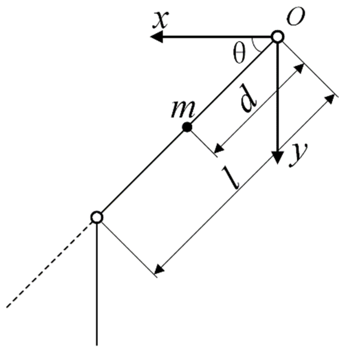
Figure 1. Hip joint dynamics model.
Processes 13 03250 g001
Figure 2. Structure of the PID control system.
Processes 13 03250 g002
Figure 3. Structural principle of the fuzzy PID controller.
Processes 13 03250 g003
Figure 4. Fuzzy Surfaces for ∆kp, ∆ki, and ∆kd.
Processes 13 03250 g004
Figure 5. Flowchart illustrating the parameter optimization process for the hybrid slime mould algorithm-fuzzy PID controller.
Processes 13 03250 g005
Figure 6. (a) Iterative optimization fitness curve of the slime mould algorithm (SMA). (b) Iterative optimization fitness curve of the particle swarm optimization (PSO) algorithm.
Processes 13 03250 g006
Figure 7. Illustrates the optimization curve for parameter iteration in the slime mould algorithm (SMA). (a) Change in Ckp, Cki and Ckd parameters. (b) Change in Ke and Kec parameters.
Processes 13 03250 g007
Figure 8. Control system for the hip joint of the lower-limb exoskeleton.
Processes 13 03250 g008
Figure 9. Comparative analysis of hip joint motion trajectory tracking curves during human flat walking utilizing four distinct control methods.
Processes 13 03250 g009
Figure 10. Comparative analysis of hip joint motion trajectory tracking errors during human flat walking utilizing four distinct control methods.
Processes 13 03250 g010
Figure 11. Comparative analysis of hip joint motion trajectory tracking curves during human slope walking utilizing four distinct control methods.
Processes 13 03250 g011
Figure 12. Comparative analysis of hip joint motion trajectory tracking errors during human slope walking utilizing four distinct control methods.
Processes 13 03250 g012
Figure 13. Comparative analysis of hip joint motion trajectory tracking curves during human stair walking utilizing four distinct control methods.
Processes 13 03250 g013
Figure 14. Comparative analysis of hip joint motion trajectory tracking errors during human stair walking utilizing four distinct control methods.
Processes 13 03250 g014
Figure 15. Experimental platform for the lower-limb exoskeleton hip joint robot.
Processes 13 03250 g015
Figure 16. Data collection process for test subjects: (a) flat ground, (b) slope, and (c) stairs.
Processes 13 03250 g016
Figure 17. (a) Hip joint movement trajectories of test subjects walking on flat ground utilizing four distinct control methods. (b) Tracking errors of hip joint movement trajectories during flat walking by test subjects under four distinct control methods.
Processes 13 03250 g017
Figure 18. (a) Hip joint movement trajectories of test subjects walking on a slope utilizing four distinct control methods. (b) Tracking errors of hip joint movement trajectories during slope walking by test subjects under four distinct control methods.
Processes 13 03250 g018
Figure 19. (a) Hip joint movement trajectories of test subjects walking up stairs utilizing four distinct control methods. (b) Tracking errors of hip joint movement trajectories during stair walking by test subjects under four distinct control methods.
Processes 13 03250 g019
Table 1. Fuzzy rule table for ∆kp, ∆ki, and ∆kd.
Se/SecNBNMNSZOPSPMPB
NBPB/NB/PSPB/NB/NSPM/NM/NBPM/NM/NBPS/NS/NBZO/ZO/NMZO/ZO/PS
NMPB/NB/PSPB/NB/NSPM/NM/NBPS/NS/NBPS/NS/NBZO/ZO/NMZO/ZO/PS
NSPM/NB/ZOPM/NM/NSPM/NS/NSPM/NS/NMZO/ZO/NSNS/ZO/NSNS/PS/ZO
ZOPM/NM/ZOPM/NM/NSPM/NS/PMZO/ZO/NSPS/PS/NSNM/PM/NSNM/PM/ZO
PSPS/NM/ZOPS/NS/ZOZO/ZO/ZONS/PS/ZONS/PS/ZONM/PM/ZONM/PB/ZO
PMPS/ZO/PBZO/ZO/NSNS/PS/PSNM/PS/PSNM/PM/PSNM/PB/PSNB/PB/PB
PBZO/ZO/PBZO/ZO/PMNM/PS/PMNM/PM/PMNM/PM/PSNB/PB/PSNB/PB/PB
Table 2. Parameters associated with the tracking process of each control system during flat ground walking.
Control Systems/Performance MetricsAdjustment Time/sMaximum Error Value/RadSteady-State Error Peak Value/Rad
PID control2.3560.11170.10835
Fuzzy PID control2.0980.092910.03036
PSO-Fuzzy PID control1.7930.085550.02922
SMA-Fuzzy PID control1.5230.051810.014416
Table 3. Parameters associated with the tracking process of each control system during slope walking.
Control Systems/Performance MetricsAdjustment Time/sMaximum Error Value/RadSteady-State Error Peak Value/Rad
PID control2.5560.12580.08892
Fuzzy PID control1.7630.098270.03006
PSO-Fuzzy PID control1.6810.088090.03031
SMA-Fuzzy PID control1.1820.034210.012153
Table 4. Parameters associated with the tracking process of each control system during stair ascent.
Control Systems/Performance MetricsAdjustment Time/sMaximum Error Value/RadSteady-State Error Peak Value/Rad
PID control2.7020.16170.1314
Fuzzy PID control1.4700.054720.09163
PSO-Fuzzy PID control1.2760.11670.04666
SMA-Fuzzy PID control1.0300.054720.012153
Disclaimer/Publisher’s Note: The statements, opinions and data contained in all publications are solely those of the individual author(s) and contributor(s) and not of MDPI and/or the editor(s). MDPI and/or the editor(s) disclaim responsibility for any injury to people or property resulting from any ideas, methods, instructions or products referred to in the content.