1. Introduction
In oilfield development, water injection is a key technical measure to maintain formation pressure, achieve stable production, and improve oil recovery. As a porous medium, the pore and micro-fracture structure developed inside the reservoir rock interacts with the injected water during the water injection process. This interaction not only changes the seepage characteristics of the reservoir, but also significantly affects the physical and mechanical properties of the rock, which in turn has an important impact on subsequent drilling projects (especially the rock breaking efficiency of the PDC bit). Studies have shown that long-term water injection leads to changes in mechanical properties such as rock-strength weakening and plasticity enhancement, which directly affects the cutting performance and rock-breaking efficiency of the drill bit. Therefore, it is of great value to engineering applications to study the evolution of the physical and mechanical properties of rock formations in the later stage of water injection for optimizing PDC bit design and improving drilling efficiency [
1,
2,
3,
4,
5].
The influence of water–rock interaction on rocks’ mechanical properties is an important topic in the field of petroleum engineering. A large number of studies have shown that changes in water saturation will significantly change the mechanical properties of rock, which has a direct impact on drilling engineering in the later stage of water injection development. A study of sedimentary rocks [
6] showed that the content of clay minerals was a key factor affecting the water sensitivity of rocks. The higher the clay content, the lower the strength and stiffness of rocks. JOSH M [
7] systematically analyzed the geomechanics and seepage characteristics of shale through comprehensive experimental methods such as triaxial compression, permeability, and acoustic wave testing. The results showed that the strength of clay-rich samples was reduced by up to 40% after water exposure. Hawkins [
8] systematically studied the water-sensitivity effect on sandstone’s mechanical properties by controlling the water content of sandstone in a laboratory test. An increase in water content lead to a decrease in uniaxial compressive strength by 15–40% and a decrease in elastic modulus by 20–35%. Erguler [
9] and Perera [
10] confirmed through experiments that, with an increase in water saturation, the uniaxial compressive strength and elastic modulus of rock decreased exponentially according to the power law function. Hickman [
11] proposed a new constitutive model, which quantitatively describes the time-varying influence of pore fluid on rocks’ mechanical behaviors by introducing a ‘weathering state parameter’. The increase in water saturation leads to a significant decrease in rock-fracture toughness. The deterioration of the mechanical properties directly affects the rock-breaking efficiency of a PDC bit, which is a key factor that must be considered in the optimization design of the bit.
Although research on the deterioration mechanism of rocks’ mechanical properties in water injection reservoirs in China started late, a series of important advances have been made in recent years. These results provide an important theoretical basis for the optimization of the design of PDC bits for use in the later stage of water injection. Kang Hongpu [
12], Ma Zhanguo [
13], and Xu Lihua [
14] confirmed that water soaking significantly reduced the compressive strength and elastic modulus of rocks through mechanical experiments, and that the softening effect was closely related to mineral composition. Li [
15] confirmed through experiments and numerical simulations that the compressive strength and elastic modulus of jointed sandstone under the action of water on the rock decreased significantly with increases in immersion time. Liu [
16] developed the enhanced tangent plane algorithm (ECPA) by establishing the anisotropic meso-damage constitutive model of brittle rock under hydraulic coupling conditions, and revealed the significant influence of pore water pressure on rock micro-crack propagation and strength degradation. Chen Yu [
17] changed the microstructure of rock by dissolution, roughening, and secondary minerals, and then affected its macroscopic mechanical behavior, which had an important influence on the stability of geotechnical engineering. Long-term waterflooding induces a coupled deterioration mechanism—mineral softening, micro-crack propagation, and micro-structural alteration—that causes continuous declines in compressive strength and elastic modulus and a brittle-to-ductile transition in reservoir rocks. These quantifiable mechanical degradation laws provide the core theoretical foundation for optimizing PDC bit designs for use in the late stages of waterflooding [
18,
19,
20,
21,
22,
23,
24,
25].
This study addresses the rock-strength degradation in reservoirs during the late stages of water injection development. Through comparative experiments on the mechanical properties of rocks before and after water injection, it focuses on revealing the time-dependent weakening effect of water–rock interaction on rock strength. By integrating changes in mineral composition with mechanical responses, the research identifies the dominant mechanisms leading to the decline in the rate of penetration (ROP) in the target formation, thereby establishing an effective bridge from mechanistic analysis to engineering design. The findings provide critical experimental evidence and a numerical simulation basis for optimizing PDC bit design, adjusting drilling parameters, and enhancing wellbore stability control in the late phase of water injection development.
2. Test of Rock Mechanical Properties
2.1. Experimental Materials and Preparation
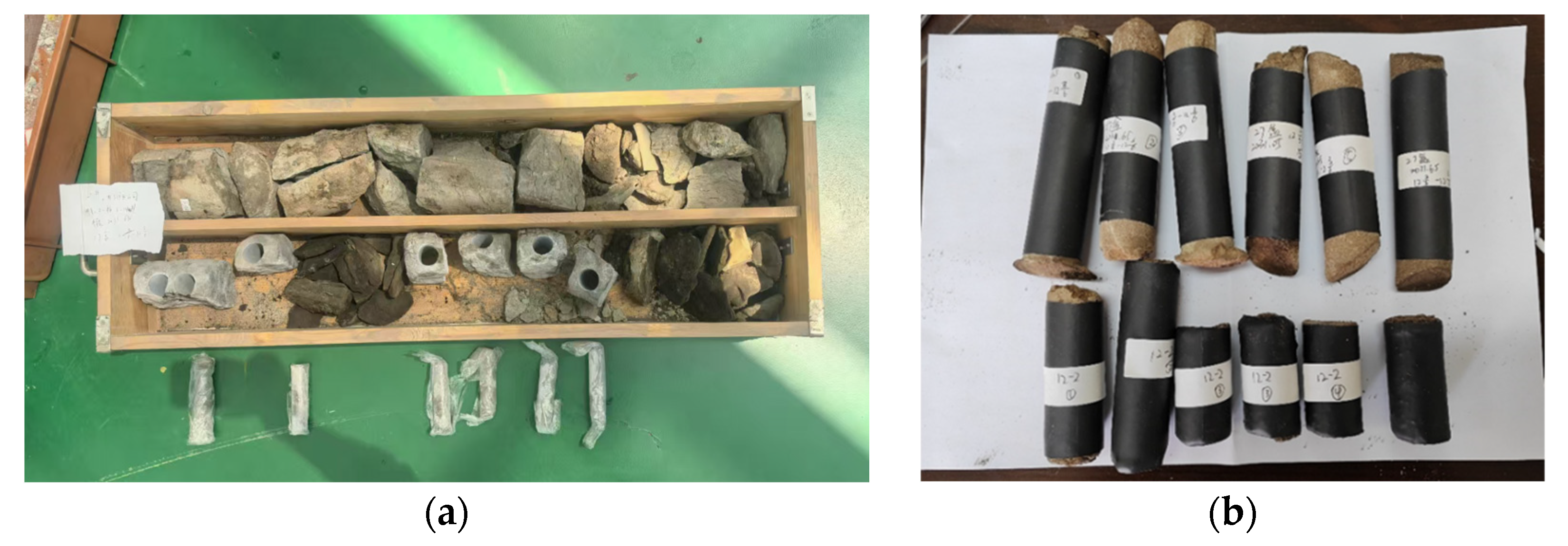
The natural sandstone cores used in this study were taken from a reservoir of 1900–2100 m depth in a block of the Shengli Oilfield. According to the water injection development history and logging data of the block, the core was divided into two groups: one group was the original non-water injection core, and the other group was the water injection core with continuous water injection. The coring photos are shown in
Figure 1.
Due to the obvious brittle characteristics of the core samples, in order to ensure the integrity of the cores and avoid structural damage during the subsequent experiments, heat-shrinkable casing (thermoplastic pipe) was used to plasticize the cores immediately after the on-site sampling. The specific operation process was as follows: (1) firstly, transparent heat-shrinkable casing with matched diameter was sheathed on the surface of the fresh core; (2) a hot air gun was used for uniform heating in the temperature range of 120–150 °C; (3) after the thermoplastic pipe completely shrunk and tightly wrapped the core, it was naturally cooled, and the sample was finalized. This processing method can effectively prevent mechanical damage to the core during storage and experimental preparation while maintaining its original water-bearing state and providing a non-destructive sample basis for subsequent rock mechanics testing and microstructure analysis.
2.2. Mechanical Properties and Mineral Composition Analysis
In this study, the cores from the depth of 1900–2100 m in the Shengli Oilfield were standardized and prepared according to the test specifications of the International Society of Rock Mechanics: the core was processed into a cylindrical standard specimen with a diameter of 25 mm × a height of 50 mm for triaxial compression mechanical property testing; at the same time, the samples were ground to below 200 mesh, and the mineral composition analysis was carried out by X-ray diffractometer (XRD). All samples were prepared at a constant temperature and humidity in a laboratory environment to ensure the accuracy and reliability of the experimental data and to provide a standardized experimental basis for studying the effect of long-term water injection on the physical and mechanical properties of tight sandstone.
2.2.1. Mechanical Property Research
To quantitatively characterize the deterioration effects of long-term water injection on the mechanical properties of reservoir rocks, this study systematically calculated key mechanical parameters of each specimen based on stress–strain curves obtained from triaxial compression tests. Through comparative analysis of parameter variations (including elastic modulus and Poisson’s ratio) between non-injected and water-injected core samples, the attenuation degree of rock mechanical performance caused by long-term water injection was quantified. Samples 1-1 to 1-6 represent pre-injection cores, while samples 2-1 to 2-6 correspond to post-injection cores. The relevant experimental results are shown in
Table 1.
The experimental data show that the elastic modulus of water-injected rock cores decreases by an average of 47.2%, the Poisson’s ratio increases by 50.3%, and the compressive strength decreases by an average of 39.7%. These results indicate that long-term water injection significantly weakens the deformation resistance of the rock. These precisely quantified mechanical parameters provide essential constitutive relationship data for subsequent finite element simulations of PDC bit–rock interaction, particularly establishing an experimental foundation for developing numerical models that account for the time-dependent effects of water–rock interaction.
2.2.2. Mineral Composition Analysis
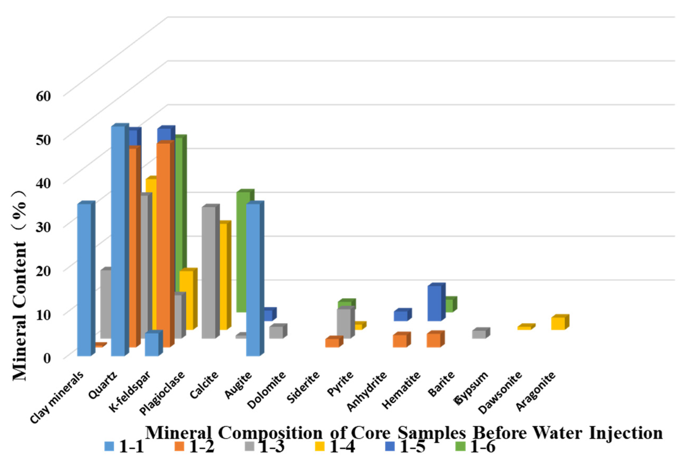
Long-term water injection significantly affects the mineral composition of formation rocks through the coupled effects of physical scouring and chemical reactions. On the one hand, high-pressure water flow continuously dissolves soluble minerals and erodes microfracture fillings. On the other hand, over decades of water injection, clay minerals undergo hydration and swelling and aluminosilicate minerals experience hydrolysis and dissolution while secondary minerals are generated and cementing materials are corroded. Based on the X-ray diffraction (XRD) test results, professional analysis software was employed to perform whole-pattern fitting and peak search processing of the diffraction spectra, enabling precise calculation of whole-rock mineral composition content in the core samples. The mineral composition distribution characteristics are shown in
Figure 2 (non-water-injected cores) and
Figure 3 (water-injected cores):
Comparative analysis of mineral composition before and after water injection demonstrates systematic alterations in sandstone mineralogy within the target block. Quartz content increased markedly from 36.6% to 48.2%, while feldspar minerals exhibited differential responses: K-feldspar rose from 9.2% to 14.8%, whereas plagioclase decreased from 19.9% to 12.1%. Calcite content declined from 9.9% to 7.2%. This mineralogical evolution reveals two dominant mechanisms during prolonged water injection: plagioclase dissolution and calcite leaching promote secondary porosity development, while K-feldspar precipitation and quartz enrichment establish a new mineral equilibrium. The loss of clay minerals weakens intergranular cementation, resulting in reduced rock cohesion, increased porosity, significantly diminished strength, and enhanced plastic deformation capacity.
Analysis of the data indicates that the decrease in the rate of penetration (ROP) is primarily attributable to the hydration of the clay minerals. Although rock strength is reduced, severe hydration significantly increases the risk of bit balling during drilling. Accordingly, in the PDC bit design developed in this study, particular emphasis was placed on optimizing the nozzle configuration to prevent bit balling. This optimization effectively improves bottom hole flow field dynamics and enhances cutting-transport efficiency, thereby substantially mitigating the risk of bit balling and ultimately leading to an increase in ROP.
2.3. Analysis of Drillability Characteristics Across Entire Well Section
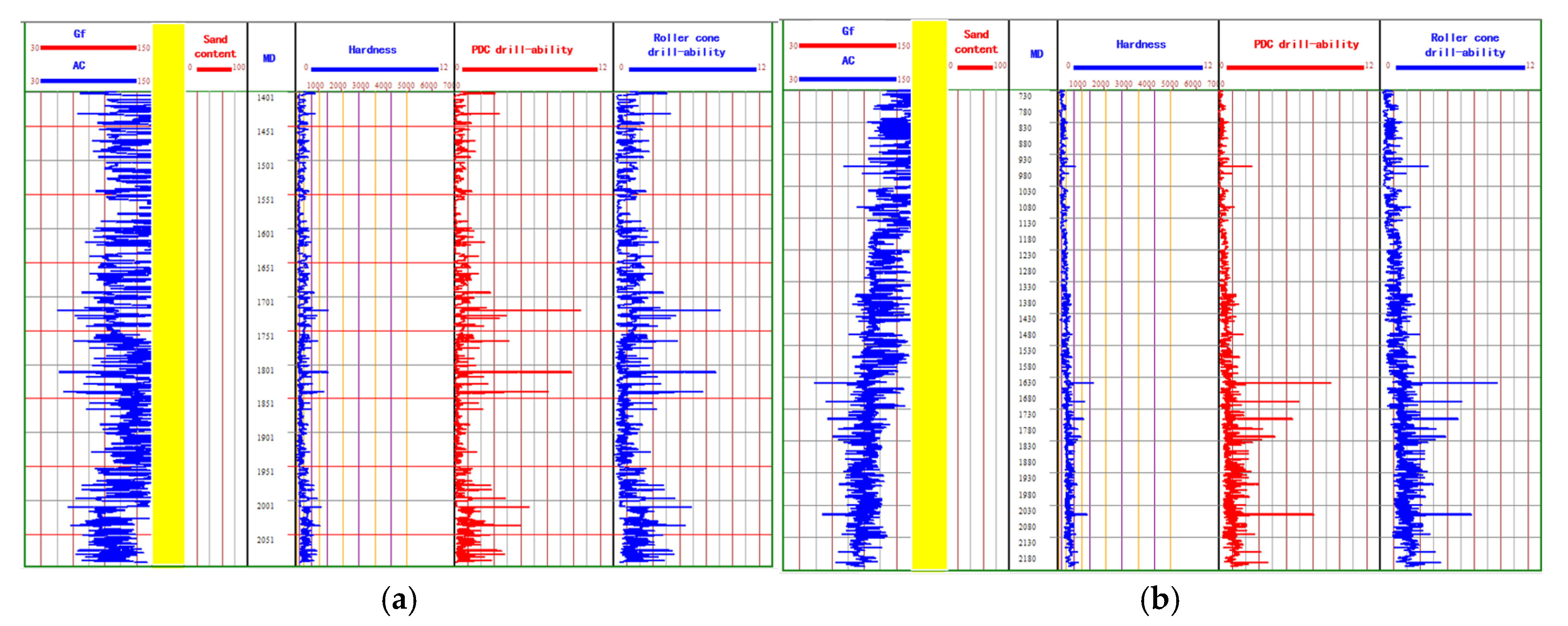
This study investigates the lateral and vertical distribution patterns of drillability parameters (including hardness, drillability, and abrasiveness) through sampling measurements of rock drillability characteristics in the target block supplemented by existing drilling data (such as well logging data, mud logging data, well history data, and core data). The specific details are illustrated in
Figure 4.
Based on the analysis of drillability profiles, the hardness and drillability parameter distribution characteristics of formations at specific depths in the target block can be accurately determined. The research reveals that water injection development has significantly altered the mechanical properties of the formations: comparative analysis shows that the original formations exhibited high drill resistance and good homogeneity, while the water-flooded formations demonstrate obvious mechanical weakening effects with significantly reduced drill resistance (primarily due to the dissolution of feldspar minerals, hydration of clay minerals, and the development of microfractures) and substantially increased heterogeneity indices. This evolutionary pattern of engineering-geological characteristics provides a scientific basis for drill bit optimization design. This study proposes a differentiated design method based on blade configuration optimization, achieving precise matching between bit structural parameters and formation characteristics, thereby significantly enhancing drilling efficiency.
3. Optimized Design of High-Efficiency PDC Bit Series
Based on the correlation analysis between rock mechanical properties and drillability parameters in water-injected formations, this study systematically conducts serial optimization research for high-efficiency PDC bits. First, quantitative relationships between cutting parameters and rock mechanical responses are established through single-cutter rock breaking experiments. Then, based on the heterogeneous characteristics of drillability profiles, a graded differential optimization scheme for bit structure is proposed.
3.1. Single-Cutter Rock Breaking and Cutting Parameter Optimization
3.1.1. Cutter Geometry Optimization
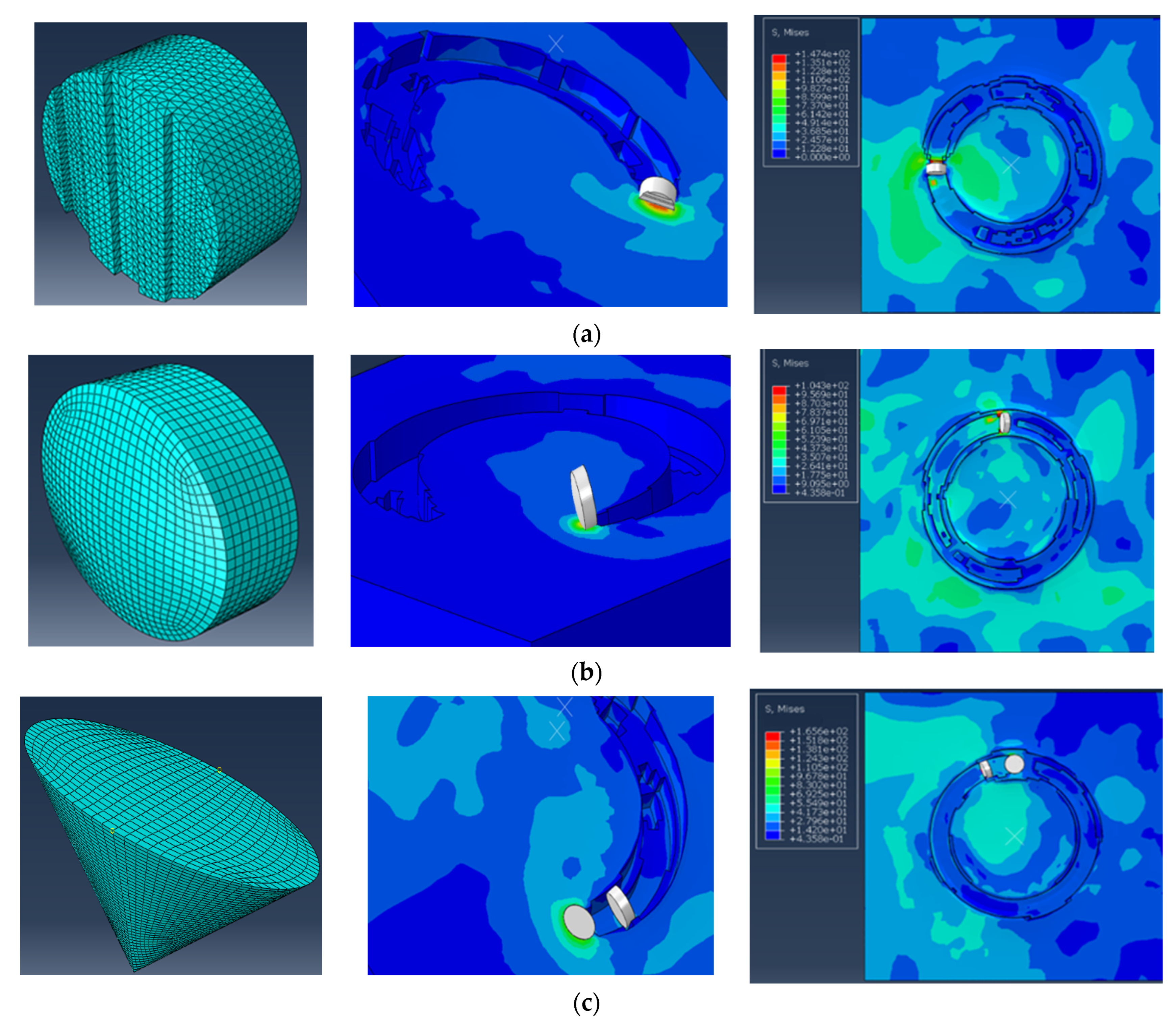
In the rock-breaking process with a single PDC bit cutter, the cutter shape design is one of the key factors affecting rock-breaking efficiency, cutting force, and tool wear. Common PDC cutter types include corrugated cutters, spherical cutters, conical cutters, and conventional flat cutters. Different cutter shapes significantly impact specific rock-breaking energy, cutting stability, and bit life by altering contact area, stress distribution, and cutting flow characteristics. Through comparative finite element numerical simulation analysis of the rock-breaking mechanisms of various cutter shapes, a theoretical basis is provided for an optimized bit design [
26,
27,
28,
29,
30]. The simulation results of different cutter types are presented in
Figure 5.
Based on the results of the rock-breaking simulations of the different cutters, the composite layout scheme of conical and conventional cutters demonstrates optimal rock fragmentation efficiency. This combination significantly enhances stress concentration at the cutter–rock interface by optimizing the distribution of the cutting stress field, while also improving the secondary fragmentation efficiency of cuttings. Compared to wave-shaped and spherical cutter configurations, this solution shows significant advantages in key performance indicators such as borehole formation quality, specific energy of cutting, and rate of penetration. The underlying mechanism primarily stems from the synergistic rock-breaking effect formed by the leading fragmentation action of conical cutters and the efficient cutting effect of conventional cutters. The findings of this study provide important theoretical support for the optimization of the design of the bit cutting structure in the target block.
3.1.2. Back Rake Angle Optimization
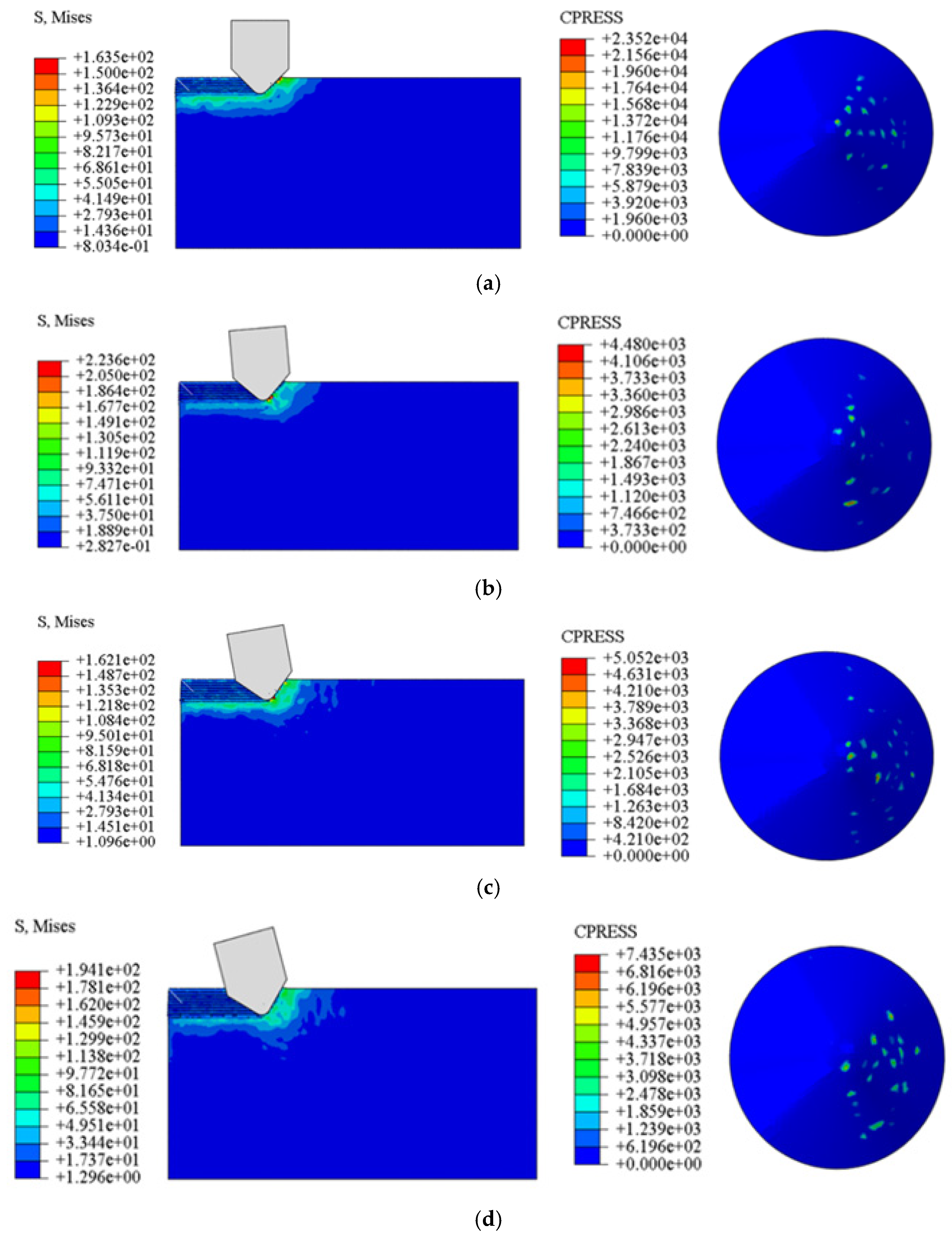
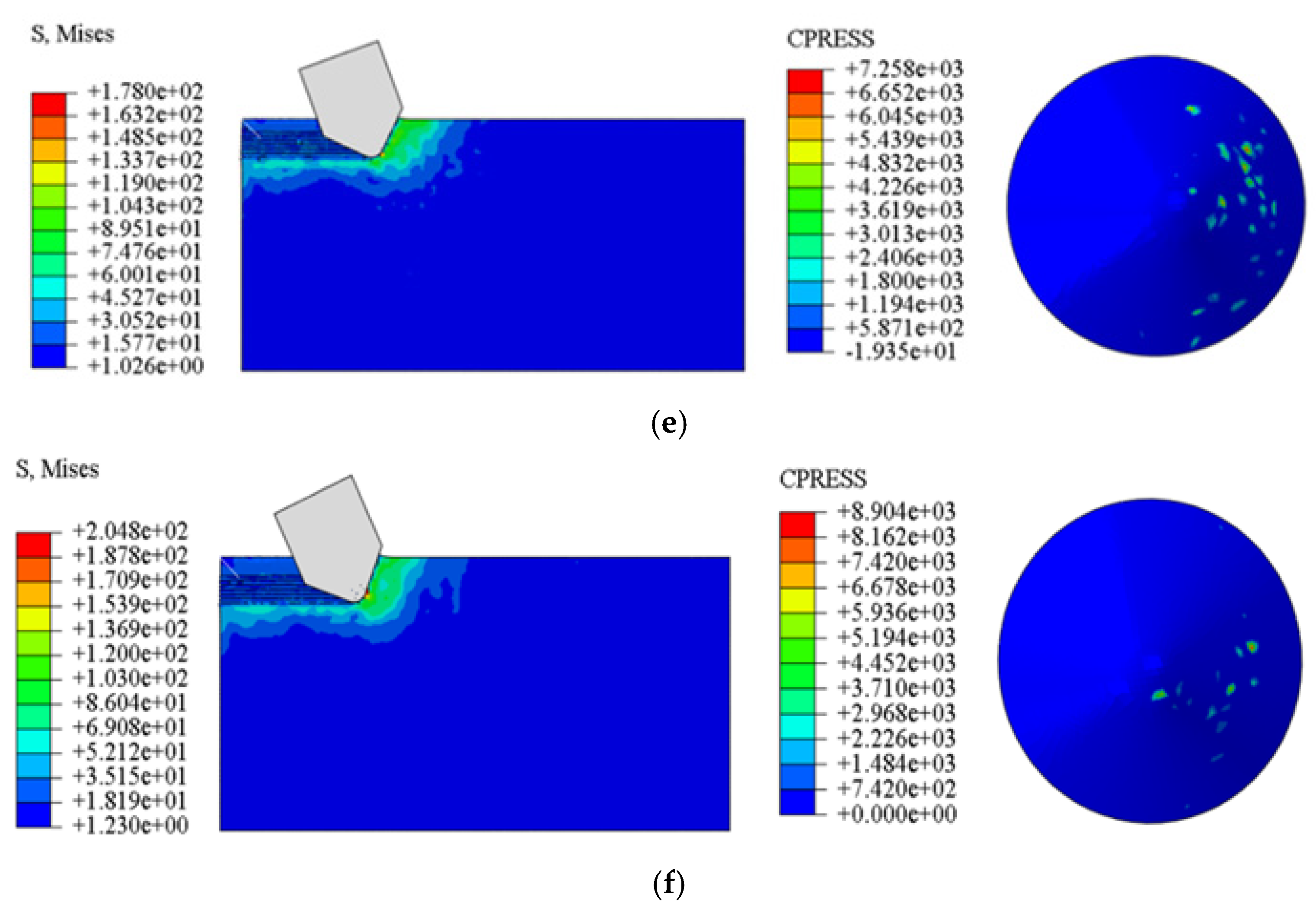
Using parametric modeling methods, this study systematically investigates the influence of back rake angles (0°, 5°, 10°, 15°, 20°, 25°) on the rock-breaking performance of PDC cutters. The simulation adopts displacement-controlled loading, applying constant normal load on the cutter while monitoring key parameters including cutting forces, chip morphology, and stress field distribution as shown in
Figure 6:
By analyzing the stress nephograms and contact pressure diagrams of rock fragmentation by conical PDC cutters with back rakes of 0°, 5°, 10°, 15°, 20°, and 25°, the stress distribution around the cutters under different back rake angles can be visually observed. The nephograms clearly show that as the back rake angle changes, both the degree of stress concentration and the distribution range in the contact area between the cutter and the rock undergo significant alterations. To quantify this variation more clearly, the stresses under each working condition were extracted and analyzed, with the results presented in the lower section of
Figure 7.
When the back rake angle of the cutter is 0°, the maximum stress is concentrated in a small area of the formation directly ahead of the cutter. As the rake angle increases, both the stress magnitude and its affected area expand accordingly. At a 15° back rake angle, the cutter generates greater internal stress within the formation, producing a wider high-stress zone. However, further increasing the rake angle beyond 15° results in minimal changes to the stress distribution range. Therefore, the 15° back rake angle yields optimal rock-breaking performance, which is consistent with conclusions drawn from studies on the relationship between PDC cutter loading and back rake angles. In the numerical simulation of cutter–rock interaction, the stress reaches its maximum and becomes highly concentrated at the top contact point between the cutter and rock. This area typically corresponds to the most severe wear location on the drill bit’s cutting structure.
3.2. Differentiated Bit Structure Design
Based on experimental rock mechanical characterization and a drillability profile analysis, this study proposes a differentiated bit optimization scheme tailored to the target block. The design follows a stress equalization concept, with its structural layout strictly adhering to mechanical balance criteria and drawing on the “integrated customization” approach of Jamshidi [
31] for complex structural/pressure regimes to incorporate both fault-intensive zones and high-pressure transitions into the cutter and gauge strength checks. For the hydraulic design, the dimensions and placement of each fluid channel are calculated through accurate flow allocation based on the rock-fracturing equivalent, while the machine learning pore-pressure results of Delavar & Ramezanzadeh [
32] are employed to pre-assign ECD limits for potentially overpressured intervals, ensuring that hydraulic parameters match the formation’s pressure window. The PDC cutting system adopts a full-bottom-hole-coverage cutter layout; spatial topology optimization guarantees that the cutting tracks contain neither overlapping blind zones nor missed regions, maximizing rock-breaking efficiency.
The numerical simulation results of rock fragmentation by the 4-blade full bit are presented in
Figure 8.
The numerical simulation results of rock fragmentation by the 5-blade full bit are presented in
Figure 9.
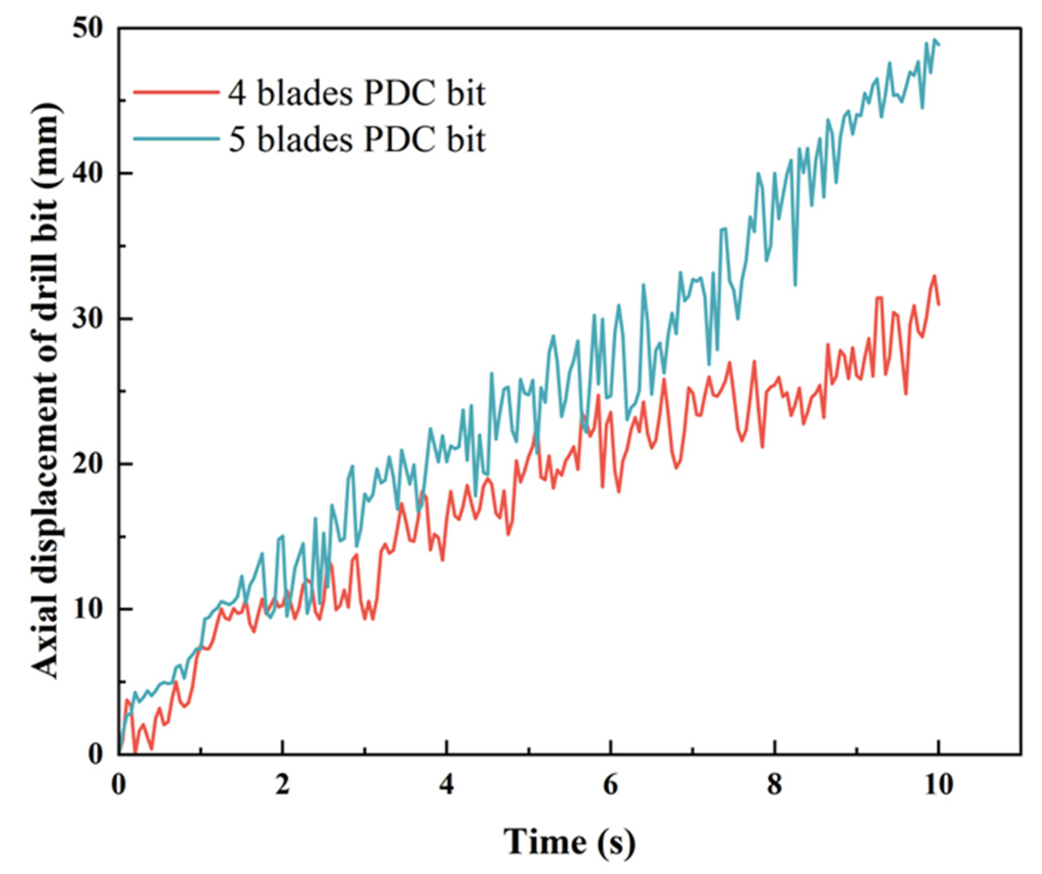
As evidenced by the axial displacement curves in
Figure 10, analysis reveals distinct performance advantages between 4-blade and 5-blade PDC bits: the 5-blade configuration achieves higher initial penetration rates, demonstrating superior rock-breaking efficiency, while the 4-blade design exhibits exceptional stability with consistent performance throughout the operation. This differentiated performance provides clear selection criteria: 5-blade bits are optimal for homogeneous formations requiring instantaneous drilling efficiency, whereas 4-blade bits are better suited for heterogeneous formations demanding stable, sustained penetration. The complementary strengths of these two designs collectively form a comprehensive formation-specific bit solution system.
4. Bottom Hole Flow Field Optimization and Balling Prevention Design
Field applications have revealed that current bit nozzle designs suffer from insufficient cutting removal efficiency and inadequate cutter cooling, leading to frequent occurrences of bit balling and high-temperature cutter failures during drilling operations. To address these nozzle design deficiencies observed in the target block’s formations, this study conducted systematic field investigations and numerical simulation analyses to optimize the bit nozzle configuration.
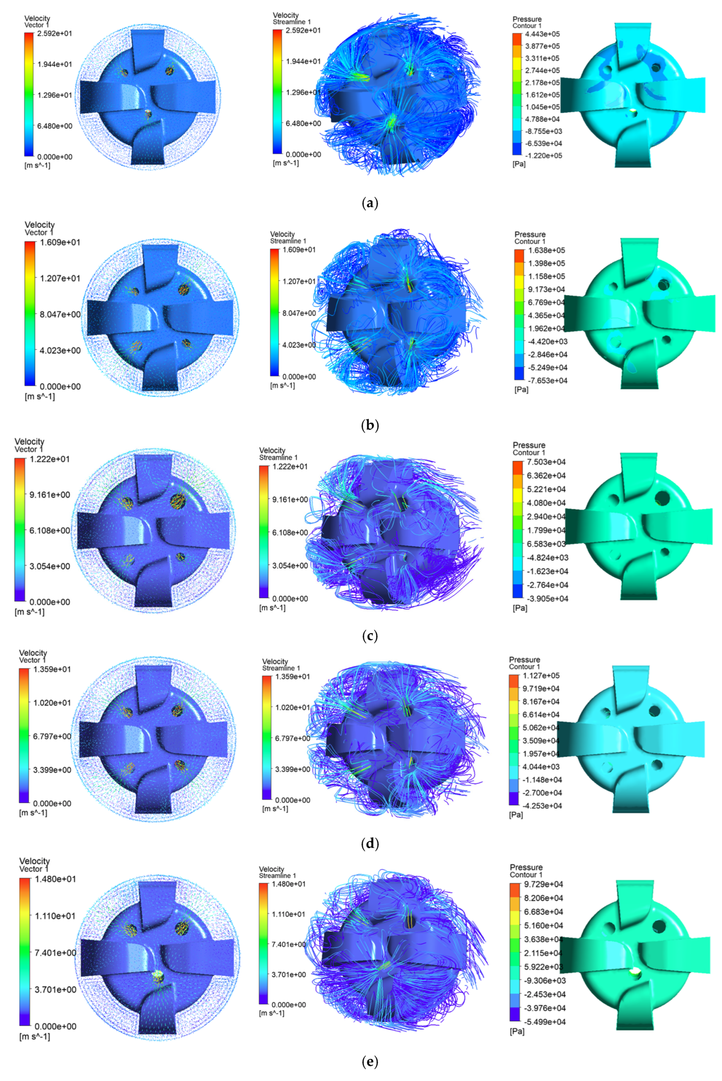
The results of the velocity flow field and the erosion force of the four-blade drill with different nozzle combinations are shown in
Figure 11:
Through a systematic comparative analysis of the flow field and erosion force simulation results for five nozzle combinations, it was found that combination (a) exhibits a narrow jet impact area with uneven bottom hole coverage, causing significant vortices on the blade sides that lead to recutting of rock cuttings and accelerated erosion ahead of the cutters; combination (c) suffers from mismatched jet energy, forming an asymmetric flow field with extensive stagnation zones and inducing high-frequency vibrations in the drill bit; although combinations (b) and (d) show improved flow symmetry, stagnation zones persist near the main blade crowns where cuttings accumulate, resulting in cooling failure, and the central nozzle’s insufficient velocity fails to clear cuttings from the well center; in contrast, combination (e) demonstrates superior overall performance—its three equal-diameter nozzles create a symmetric and stable flow field ensuring full, uniform bottom-hole coverage without vortices or stagnation zones, with reasonably concentrated jet energy that thoroughly cleans without excessive erosion, provides adequate cooling to blade crowns, cutter fronts, and flow channels, enables high cutting-transport efficiency, and distributes erosion force uniformly without stress concentration, significantly reducing erosion fatigue risks. This configuration achieves the optimal balance among cleaning efficiency, cooling performance, and bit protection, making it the final selected nozzle scheme.
The results of the velocity flow field and the erosion force of the five-blade drill with different nozzle combinations are shown in
Figure 12:
From the perspective of flow field coverage, nozzle combinations (a) and (c) generate vortex regions due to unbalanced forces between the incident and outflow directions. These vortex zones significantly impact the flow field and the ability of the fluid to carry cuttings. Within the vortices, rock cuttings continuously scour the drill bit, reducing its service life. Simulation results for combinations (b) and (d) indicate an absence of flow lines passing through the crown of the main blades, implying inadequate lubrication by drilling fluid in these areas. Regarding nozzle exit velocity, excessive nozzle pressure drops lead to excessively high exit velocity, which causes erosive damage to the bit’s nozzle holes and drill body. Conversely, insufficient velocity adversely affects bit cooling, lubrication, and bottom hole cleaning. Nozzle combination (f) provides moderate exit velocity while subjecting the drill body to lower and more uniform pressure. Based on comprehensive analysis of flow line distribution, jet velocity, and erosive forces on the drill bit, the 5 × 10 mm nozzle combination is identified as the optimal choice.
Research demonstrates that five-blade bits with multi-stage nozzle configurations are better suited for efficient drilling in hard formations, while four-blade bits with larger-diameter nozzles perform superiorly in balling-prone formations. These differentiated designs effectively address drilling requirements across various formation conditions.
5. Conclusions
Through rock mechanics testing, drillability profile analysis, and finite element modeling, this study established a formation-heterogeneity-based differentiated PDC bit design methodology. The findings demonstrate the following:
(1) Comprehensive mechanical testing (triaxial compression, XRD, etc.) confirmed long-term water injection induces significant rock mechanical deterioration: flooded cores showed 47.2% average elastic modulus reduction, 50.3% Poisson’s ratio increase, and 39.7% compressive strength decrease. Mineral analysis revealed time-dependent water–rock interaction damage mechanisms, providing critical constitutive parameters for bit design.
(2) Formation-specific bit configurations were developed: five-blade high cutter-density designs with multi-stage nozzles enhance fracturing efficiency and flow coverage for hard formations, while four-blade variable-density designs with uniform nozzles improve cutting removal and hole cleaning in water-weakened formations, effectively preventing bit balling.
(3) The developed differentiated bit system, based on coordinated optimization of rock mechanics, bit structure, and nozzle hydraulics, effectively addresses water-flooded reservoirs’ heterogeneity. Field applications achieved comprehensive drilling efficiency improvements, providing reliable technical support and engineering guidance for similar block development.
(4) The limitations of this study primarily lie in its reliance on laboratory core tests and small-scale simulations, which do not include field-scale bit trials or account for complex geological and chemical fluid conditions. Additionally, the analysis of time-dependent rock behavior remains insufficient. To address these limitations, future research will focus on conducting field tests and full-scale validation, investigating the mechanical responses of rocks under multi-factor coupling conditions, extending the applicability of the findings to different lithologies, and delving into the evolution of long-term rock strength and drillability after water injection. These efforts aim to enhance the engineering applicability and generalizability of the research outcomes.
