1. Introduction
With the widespread access to distributed energy resources (DER), small-micro parks have developed into a new type of microgrid that can flexibly interact with distribution networks [
1]. Among them, as a system where multiple distributed energy sources coexist in “source-grid-load-storage”, small-micro parks can provide flexibility to distribution networks through the point of common coupling (PCC). For example, virtual power plants can integrate decentralized flexibility resources through market mechanisms to solve problems such as power balance, peak load regulation, and insufficient voltage regulation resources in power systems, which is of great significance for improving the economic efficiency and safety of power system operations [
2,
3].
The grid-connected flexibility that this paper focuses on is specifically reflected in power flexibility: that is, the power regulation range provided by the small-micro parks to the distribution network through the PCC. Considering the internal network constraints of the small-micro parks, the grid-connected flexibility is not a simple sum of the flexibility of all distributed resources. In many scenarios, the flexibility of distributed resources cannot be effectively reflected in the common coupling node. In addition, the distributed resource points are numerous and widespread, and their operating characteristics are unstable, which in turn affects the small-micro parks’ ability to flexibly adjust externally [
4].
Regarding the optimization and dispatching strategy of PCC flexibility, reference [
5] proposed a collaborative control strategy based on the power uncertainty and voltage over-limit of the common coupling point of the active distribution network; reference [
6] established a robust model based on the cooperation of multiple microgrids in the region; reference [
7] identified the coordination and complementarity of equipment based on the flexibility control and power support capacity of interconnected devices; reference [
8] optimized the safety margin of grid-connected microgrids from the perspective of security domain; reference [
9] optimized the distributed power carrying capacity of interconnected distribution networks based on network reconfiguration. Reference [
10] proposed a distribution network energy management and operation control system architecture to realize distributed resource cluster control. Reference [
11] proposed a distribution network energy management and operation control based on machine learning to explore the active support capacity of the distribution network for the main grid. The above optimization dispatching models have not yet incorporated the potential advantages of network reconfiguration on PCC flexibility.
Network reconfiguration can optimize the power flow distribution of small-micro parks by optimizing the switch state inside the small-micro parks, thereby reducing the restrictions of network constraints on the flexibility of distributed resources and improving the overall flexibility of the small-micro parks’ grid connection. In related research, references [
12,
13,
14,
15] focus on how network reconfiguration technology can optimize the operating performance of power systems and solve practical problems, and propose that network reconfiguration technology is an important tool for optimizing power systems without adding additional equipment. Reference [
16] proposes to use network reconfiguration technology to release the flexibility of distributed resources and increase the flexibility limit of active distribution networks, but a specific feasible optimization model has not yet been established.
Considering the many complex network constraints within the small-micro parks, the expression of grid-connected flexibility is essentially a high-dimensional complex optimization problem that cannot be directly optimized in the network reconfiguration optimization target. References [
17,
18,
19] focus on the flexibility evaluation and optimization of distributed resources, focusing on the flexibility space of distributed resource output and the overall flexibility regulation capability of the system. Power flexibility aggregation provides a tool for studying the optimization of power flexibility at the common coupling point of end-to-end systems. Existing studies have proposed flexibility resource aggregation evaluation methods for different scenarios. Reference [
20] proposes a complete quantitative indicator system for flexibility resource aggregation models, which provides a basis for evaluating flexibility resources in different scenarios. Reference [
21] proposes a boundary shrinkage method based on high-dimensional polyhedrons to estimate the parameters of virtual generators and virtual batteries. Reference [
22] proposed a method for multi-period power flexibility aggregation, which aggregates the active power flexibility of the distribution system and calculates its optimal elliptical feasible area in multiple periods. Reference [
23] combined the operation constraints and the randomness of distributed resource output, proposed a data-driven combination model, and improved the computational efficiency. Reference [
24] proposed an aggregation method based on the inner approximation Minkowski sum of convex polyhedron affine transformation, which accurately quantified the regulation capacity of multivariate flexibility resources and realized the efficient aggregation of distributed resources. The above studies proposed flexibility resource aggregation evaluation methods for different scenarios, but did not consider how to optimize and improve flexibility through network reconfiguration based on the evaluation model.
This paper comprehensively considers network reconfiguration and distributed resource flexibility aggregation, fully utilizes the flexibility of all distributed resources, optimizes the grid-connected flexibility of small-micro parks, and improves the internal security of small-micro parks and the coordinated regulation capability with mutually coupled systems. The main contributions of this paper are as follows: (1) A network reconfiguration model with the goal of improving grid-connected flexibility is constructed, and the grid-connected flexibility of small-micro parks is improved by optimizing the switching strategy. (2) Through the equivalent transformation of the model, the grid-connected flexibility that cannot be expressed is transformed into a two-stage robust optimization problem, and an effective solution is achieved. (3) The effectiveness and superiority of the above-mentioned method are verified through simulation experiments. (4) The constructed model has rich application scenarios and is suitable for various end-to-end coupled systems, including small-micro parks actively supporting the upper grid and isolated interconnected small-micro parks providing flexibility to each other.
The structure of this paper is arranged as follows:
Section 2 introduces the small-micro parks’ grid-connected flexibility calculation model and constructs a two-stage robust optimization to characterize the grid-connected flexibility;
Section 3 introduces the network reconfiguration model and solution algorithm with the goal of improving grid-connected flexibility;
Section 4 verifies and analyzes the proposed method;
Section 5 summarizes the main conclusions of the full text.
2. Small-Micro Parks’ Grid-Connected Flexibility Calculation Model
2.1. Small-Micro Parks’ Grid-Connected Flexibility Characterization Method
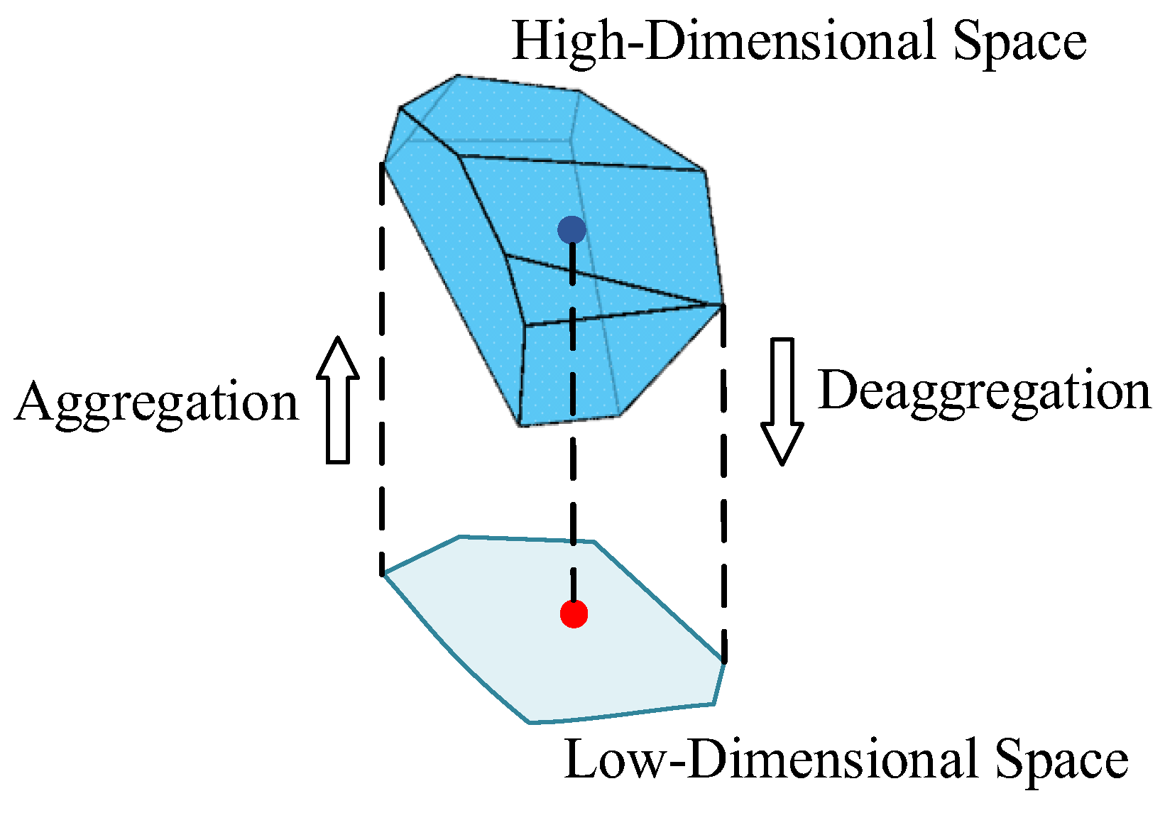
Flexibility aggregation refers to the flexibility of all distributed resources in the small-micro parks at the common coupling point under the premise of ensuring the internal voltage safety of the small-micro parks and avoiding the overload of the branch, where the flexibility resources include distributed photovoltaic, distributed energy storage, distributed wind power, adjustable load, electric vehicles, generators, etc. The essence is as follows: projecting a high-dimensional space, determined by the state variables of the flexibility resources, onto the Euclidean injection space of the state variables at the common coupling point of the small-micro parks.
The common coupling point of the small-micro parks is selected as the power flexibility aggregation point, and the flexibility of all distributed resources in the small-micro parks is aggregated at the common coupling point.
The grid-connected power flexibility is essentially the feasible domain of power at the common coupling point, which is also the dispatchable range of the system for scheduling, and the operating safety domain of the system.
The specific descriptions of the grid-connected power flexibility of the small-micro parks are:
- (1)
The set of all operating states, i.e., working points, at the common coupling point over the entire time scale under the determined network topology is called the grid-connected power flexibility of the small-micro parks.
- (2)
The grid-connected power flexibility of the small-micro parks gives the maximum grid-connected flexibility range of the system that meets the safety constraints, which facilitates the evaluation and optimization of the gateway power flexibility.
- (3)
The small-micro parks’ grid-connected power flexibility boundary is defined as the set of critical operating points that meet the system operation constraints.
- (4)
The power flexibility at PCC refers to the adjustable active/reactive power range that the park can provide to the main grid under security constraints, while the release of power flexibility denotes the process of utilizing network reconfiguration to alleviate internal constraints and thus enlarge the feasible region of PCC power.
Let us assume that the small-micro parks’ grid-connected power flexibility is
, which can be expressed as a high-dimensional polyhedron using Formula (1), where
represent the upper and lower boundaries of the small-micro parks’ grid-connected power flexibility at time t,
2.2. Equipment Flexibility Modeling
2.2.1. Distributed Photovoltaic
where
and
are the upper and lower limits of active and reactive power injected by the photovoltaic generator into node
at time
;
and
are the lower limits of active and reactive power injected by the photovoltaic generator into node
at time
;
is the apparent power capacity of the photovoltaic generator at node
. Formulas (2) and (3) are the upper and lower limits of active and reactive power of the photovoltaic generator, respectively, and Formula (4) is the capacity constraint of the photovoltaic generator at node
at time
.
2.2.2. Distributed Energy Storage System
where
is the power of the energy storage device at node
at time
;
is the charge and discharge power of the energy storage device at node
at time
;
is the energy loss coefficient of the energy storage device at node
over time;
is the time variation. Formulas (5) and (6) are the energy conservation constraints at time
and
, respectively; Formulas (7) and (8) are the upper and lower limit constraints of the charge and discharge power, and the upper and lower limit constraints of the power of the energy storage device at node
at time
, respectively.
2.3. Network Constraints
Considering that voltage is the main operating limitation of microgrids with a high proportion of distributed generation, this paper adopts the LinDistFlow power flow model [
25] that takes voltage distribution into account. This model has the advantages of linearization, high-precision voltage estimation, flexibility, and scalability, and has important application value in power system analysis and optimization. Therefore, the following power flow model for small-micro parks is established.
where
are the active and reactive power of the node
load at time
;
and
are the active and reactive power, respectively, injected into the node
branch from node
at time
;
and
are the active and reactive power, respectively, flowing out of node
at time
;
and
are the voltage amplitudes of the first node
and the last node
of branch
, respectively;
is the resistance of branch
;
is the reactance of branch
;
is the upper limit of the capacity of branch
.
Equations (9) and (10) are the node active and reactive power balance equations, respectively; Equation (11) is the branch voltage drop equation, and Equation (12) is the branch capacity constraint.
2.4. Grid Connection Flexibility Calculation Method
In order to express the model, all state variables at time
are written in the form of the vector
, as shown in Formula (13):
According to the small-micro parks’ power flow model, flexibility resource modeling, and the defined vector
, the small-micro parks’ integrated system can be written as shown in Equations (14)–(17):
where
and
are the active and reactive power at the common coupling point of the small-micro parks, respectively;
are the coefficient matrices of the state variables,
are the given system parameters, such as node load power, branch resistance
, branch reactance
, etc.;
is the total number of second-order cone constraints.
Equations (14) and (15) are the active and reactive power balance equations of the small-micro parks PCC, respectively; Equation (16) contains all the second-order cone constraints, such as Equations (4) and (12); Equation (17) contains other network constraints.
Since the constraints in the battery energy storage system model have time-coupling characteristics, in order to simplify the expression of the coefficient matrix and facilitate problem solving, the following constraints need to be introduced:
where
are coefficient matrices;
are given parameters. Equations (18) and (19) are model expressions of Equation (6); Equation (20) is a model expression of Equation (5).
According to the power flexibility characterization method, the objective function of the grid-connected flexibility aggregation model can be written as shown in Formula (21):
The power flexibility
of the common coupling point has the maximum internal approximation of the true solution. For any operating point in the aggregation
, a corresponding operating point
can be found after deaggregation. The flexibility resources are regulated and managed through scheduling instructions, so Equation (22) should be satisfied.
Therefore, the constraints of the small-micro parks’ grid-connected flexibility calculation model can be written as Formula (23), where the constraints include all safety constraints and power flow constraints.
The mathematical perspective of the model is as follows: projecting a high-dimensional space determined by the DER state variables onto the Euclidean space of a low-dimensional space
, where the small-micro parks’ PCC state variables are located, and any operating point in its low-dimensional space can be mapped to the high-dimensional space determined by the DER state variables, that is, the disaggregation feasibility is met.
Figure 1 is a schematic diagram of the grid-connected flexibility calculation principle.
Therefore, the above problem can be written as a two-stage adaptive robust optimization model. In order to verify whether the maximum power flexibility obtained by aggregation meets the feasibility of deaggregation, some operating points are randomly selected for verification. It is not conservative to verify that each operating point in the maximum power flexibility space of the small-micro parks’ PCC is obviously infeasible.
To this end, we first introduce the uncertain parameter
to represent
. According to the continuity of the feasible domain, a is taken as
decimal between 0 and 1, which is equivalent to taking an interpolation between
and
, ensuring that every operating point in the maximum power flexibility space of the small-micro parks’ common coupling point can be taken.
The uncertain parameter
is defined to belong to the uncertainty set
, expressed by Formula (25):
Based on the above, a two-stage adaptive robust peer-to-peer model shown in Equations (26) and (27) is established to calculate the active power flexibility of the small-micro parks’ PCC.
The optimization objective (26) in the first stage is the upper and lower limits of the maximum power flexibility, in order to find the maximum power flexibility of the small-micro parks’ common coupling point; in the second stage, a flexible resource scheduling scheme is implemented to ensure the feasibility of deaggregation when the uncertainty variable takes the worst scenario of the uncertainty set through double-layer optimization. The constraint condition (27) contains all network topology constraints and aggregation and deaggregation feasibility constraints.
3. Network Reconfiguration Model for Improving Grid-Connected Flexibility
3.1. Network Reconfiguration Optimization Model Construction
According to the characteristics of the open-loop operation of the small-micro parks’ closed-loop design, two integer variables
and
are introduced to ensure that the network remains in a tree structure after reconfiguration [
26].
represents the switch state of branch , represents the on-state of branch when it is set to 1, and represents the off-state of branch when it is set to 0; represents the parent node–node association matrix of node and node , and is 1 when node is the parent node of node , otherwise it is 0.
According to the graph theory-spanning tree theory, the small-micro parks’ topology conditions have the following characteristics: each node except the common coupling point has only one parent node, and the root node has no parent node. This can be expressed by constraint (29):
If branch
exists, then node
is the parent node of node
, that is,
. At the same time, it is necessary to ensure that node
is not the parent node of node
, that is,
. This can be expressed by constraint (30):
When branch
is disconnected, it should be ensured that the active power
and reactive power
on branch
are 0, so Equation (12) should be written as shown in Equation (31):
If branch
is disconnected, since constraint (31) will limit
and
to 0, Equation (11) will also become Equation (32), that is, the voltage amplitudes at both ends of the unconnected branch
are forced to be equal, which is obviously incorrect. Therefore, the
method is introduced to write Equation (11) as shown in Equations (33)–(35):
According to the small-micro parks’ network model in
Section 2, a reconfiguration model for small-micro parks is established, as shown in Equations (36) and (37). The optimization objective of this model is Equation (36), and Equation (37) includes all safety constraints, power flow constraints, and radial constraints of the small-micro parks’ operation and network reconfiguration.
3.2. Network Reconfiguration Model Aiming at Maximizing PCC Flexibility
Through network reconfiguration, the flexibility of new energy sources dispersed on various nodes can be explored, and the grid-connected flexibility of small-micro parks can be improved. Therefore, according to the network reconfiguration optimization model and the power flexibility aggregation model, the small-micro parks network reconfiguration problem for improving grid-connected flexibility can be written as a two-stage adaptive robust optimization model.
First, the small-micro parks’ network reconfiguration problem for improving flexibility is described as aggregating the power flexibility of distributed resources and optimizing the topology structure to obtain the maximum power flexibility of the small-micro parks’ PCC. For any operating point in the maximum power flexibility of the PCC, there is a scheduling scheme to deal with it after deaggregation.
Therefore, the outer
of the grid-connected flexibility calculation model in
Section 2.4 is combined with the
of the network reconfiguration model in
Section 3.1 to obtain a robust optimization model for maximizing grid-connected flexibility. The two-stage adaptive robust peer-to-peer model shown in Equations (38) and (39) is established to optimize the active power flexibility of the small-micro parks’ PCC.
The optimization objective (38) of the first stage optimization quantity includes the line switch state, i.e., the upper and lower limits of the maximum power-feasible region, and the purpose is to find the optimal topology structure under the maximum power flexibility of the small-micro parks’ PCC. The other specific meanings are the same as those of (26). The constraint condition (39) includes all network topology constraints and aggregation and deaggregation feasibility constraints. The difference from the small-micro parks’ grid-connected flexibility calculation model in
Section 2.4 is that the tree topology constraints (28) to (30) that the network reconfiguration needs to satisfy are included in (39), and the network constraints must also be replaced with the power flow constraints that satisfy the network reconfiguration optimization.
3.3. Model Solving Algorithm
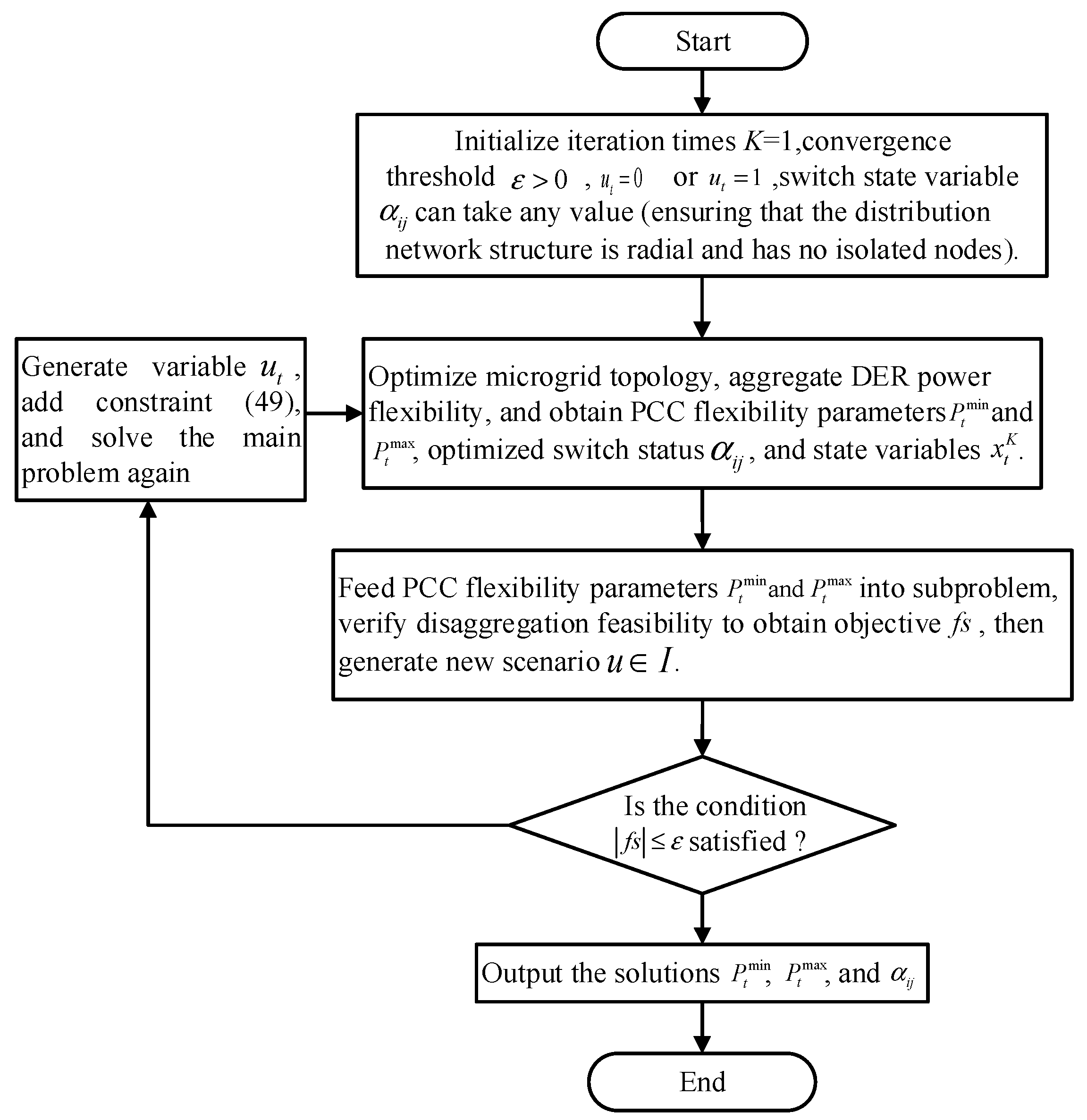
For the two-stage adaptive robust optimization problem of Equations (38) and (39), this paper adopts the column-and-constraint generation algorithm to solve it. First, the two-stage adaptive robust optimization problem is decomposed into a main problem and sub-problems, and then the main and sub-problems are iteratively solved to obtain the optimal solution. This section describes the specific decomposition and transformation process of the mathematical model of the main problem and sub-problems, as well as the iterative solution process of the column-and-constraint generation (C&CG) algorithm.
3.3.1. Main Problem Solving
According to the solution mechanism of the C&CG algorithm [
26], the first-stage max problem of the two-stage adaptive robust optimization problem is expressed as shown in Equations (40) and (41). Equation (40) is the objective function, and Equation (41) is the constraint condition.
where
represents the scenario generated by the subproblem,
is the given initial value in the first iteration,
is the current iteration number, and
is the total number of iterations.
is the solution that is adaptive to scenario
, so
adaptive solutions will be generated in
scenarios.
3.3.2. Subproblem Solving
After solving the main problem, we obtain the switch variable
that satisfies all the constraints of the main problem, the upper bound
and lower bound
of the maximum power flexibility of the PCC, and all the state variables
. Therefore, the subproblem can be expressed as a min–max optimization problem with the objective function as Equation (42) and the constraints as Equation (43):
- (1)
The dual problem of the subproblem
Since the subproblem (42) is a min–max double-layer optimization problem, in order to transform the inner max problem into a min problem and merge it with the outer min problem, it is necessary to find the duality of the inner max problem.
Assume that the Lagrange multipliers of the dual variables of constraint (43) are
, respectively. Based on the strong duality theory, the objective function will be transformed into the following Formula (44):
The main task of the sub-problem is to verify the disaggregation feasibility of the optimization result of the main problem. Since the power flexibility injection space optimized by the main problem has a convex hull, as long as the worst scenario in the power flexibility injection space aggregated by the main problem can meet the disaggregation feasibility, that is, the boundary points of the power flexibility injection space can meet the disaggregation feasibility, then all operating points in the power flexibility injection space will also meet the disaggregation feasibility.
Therefore, the value of the random variable
can be simplified to a binary variable, as shown in Equation (45). The constraints will be restated as shown in Equation (46).
- (2)
Linearization of subproblems
There is a nonlinear term
in Formula (44), which makes it difficult to solve. Therefore, the
method is used to transform the objective function into Formula (47):
In Formula (47),
are intermediate variables generated in the linearization process. When
,
,
; when
,
,
, expressed by constraint (48).
According to the above description, the subproblem will be restated as Equations (45)–(48), and the solution of the subproblem will be transformed into the solution of the mixed integer second-order cone problem, which can be solved directly using the Gurobi solver.
3.3.3. Solving Algorithm
Reference [
26] verified and compared the Benders-dual tangent plane algorithm and the column and constraint generation algorithm as the solution strategies for the two-stage robust optimization problem. Considering the excellent computational performance and insensitivity to the problem, this paper adopts the C&CG algorithm to solve the problem. The solution process is shown in
Figure 2.
After the sub-problem is solved, if the objective function value still does not meet the convergence condition, a new variable will be generated, and the new constraint (49) will be added to the main problem to continue the iteration.
4. Case Analysis
4.1. Example System Description
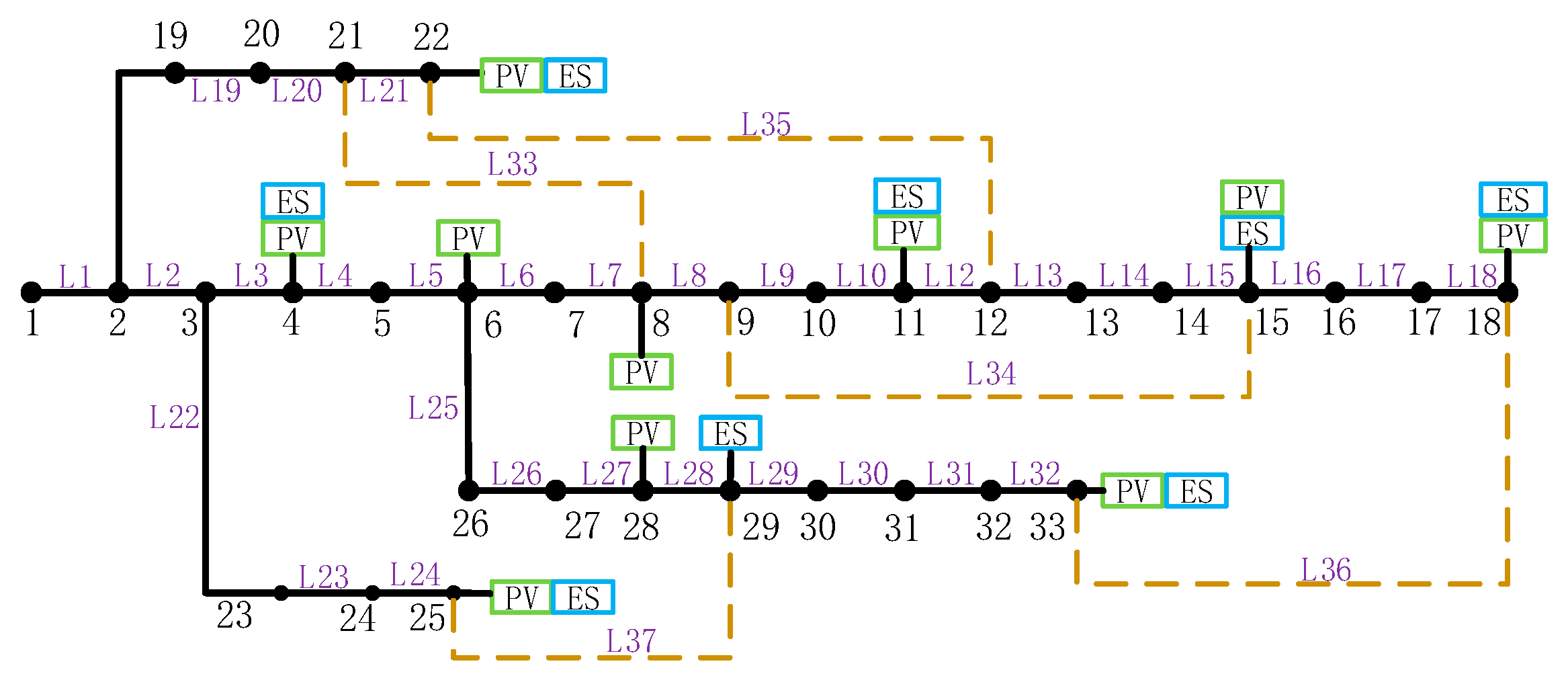
This paper uses an IEEE-33-node microgrid to verify the feasibility of the proposed method. The topology is shown in
Figure 3. L1~L32 are the conductive lines before optimization, and L33~L37 are all interconnection lines. It is assumed that node 1 is a common coupling node.
Ten photovoltaic generators and six energy storage devices are connected to the IEEE-33 node microgrid. The specific connection conditions are shown in
Table 1.
The charging and discharging efficiency of the energy storage device is 0.9, the maximum charging power is 0.2 MW/h, the maximum discharging power is 0.2 MW/h, the initial SOC is 0.3 MWh, the lower limit of the energy storage capacity is 0.15 MWh, and the upper limit of the energy storage capacity is 0.8 MWh; the installed capacity of the photovoltaic generator is 0.4 MW.
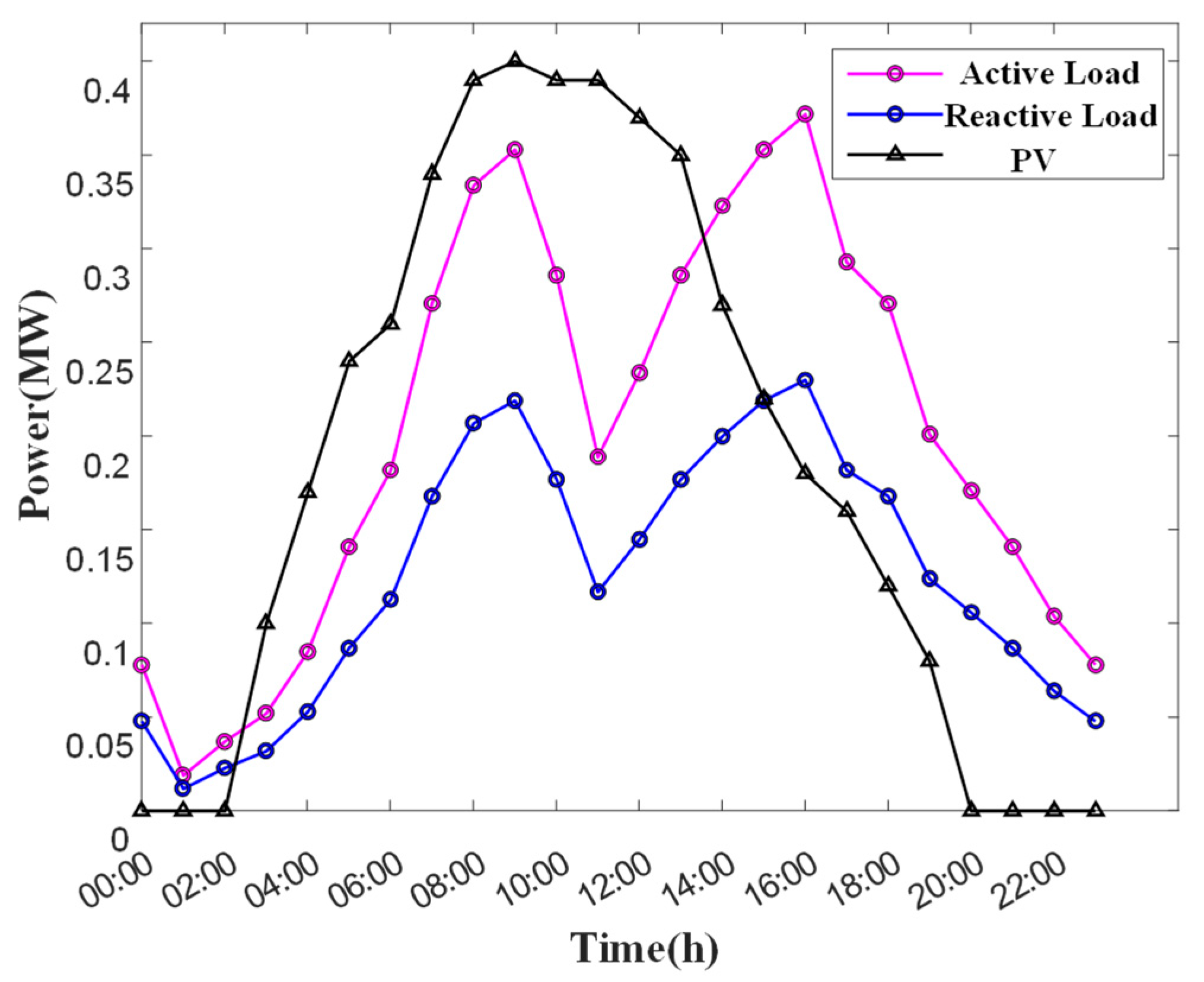
The trend of active and reactive loads and photovoltaic daily power generation in the microgrid is shown in
Figure 4.
4.2. Optimization Analysis of Microgrid Grid-Connected Power Flexibility in Two Time Periods
First, the two-stage adaptive robust optimization model proposed in this paper is intuitively explained with the goal of optimizing the small-micro parks’ grid-connected power flexibility in two time periods.
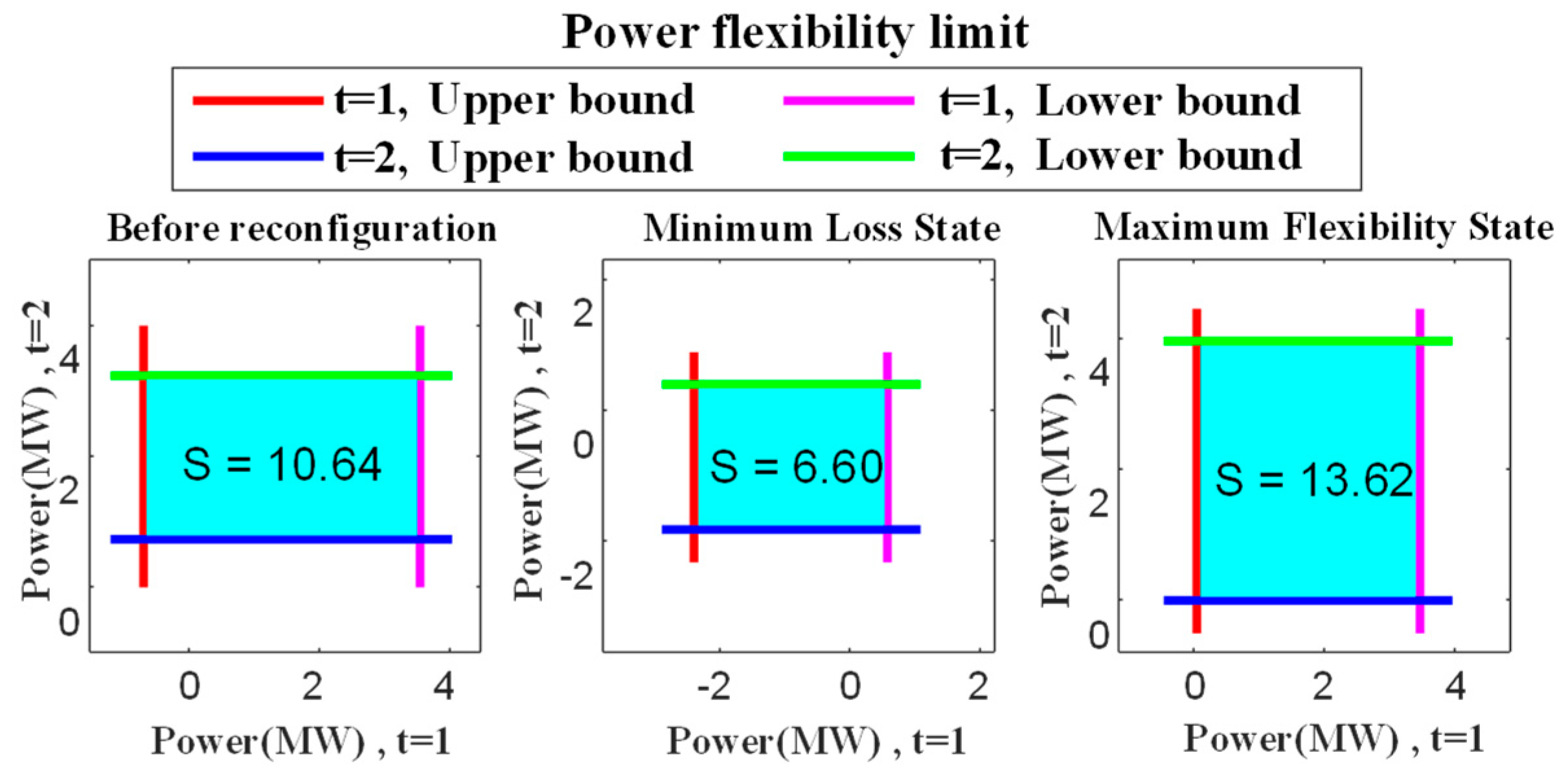
Figure 5 shows the small-micro parks’ grid-connected power flexibility before IEEE-33 node network reconfiguration in two time periods: the small-micro parks’ grid-connected power flexibility under traditional network reconfiguration with the goal of minimizing network loss, and the small-micro parks’ grid-connected power flexibility after optimization by the proposed method. Before network reconfiguration, it refers to the PCC power flexibility that only considers meeting all security constraints and aggregating flexibility resources.
From
Figure 5, it can be seen that the PCC power flexibility of the proposed method after optimization is increased by 2.98, which is nearly 28% compared with before optimization. By comparing the small-micro parks’ power flexibility under the traditional network reconfiguration with the goal of minimizing network loss and the small-micro parks’ grid flexibility after optimization by the proposed method, it can be seen that the traditional network reconfiguration with the goal of minimizing network loss cannot improve the small-micro parks’ grid flexibility.
To further illustrate that the network reconfiguration method in this paper can improve the small-micro parks’ grid flexibility,
Figure 6 shows the network topology diagram after optimization by the proposed method.
According to
Figure 6, after optimization, the disconnected branches are L8, L9, and L28, and the connected branches are L34, L35, and L37. Combined with
Table 2, it can be seen that before optimization, the line capacity of lines L8 and L9 limits the flexible release of distributed resources on nodes 11, 15, and 18, and line L28 limits the release of distributed resource flexibility on nodes 29 and 33, thereby affecting grid-connected flexibility. Therefore, network reconfiguration can improve power flexibility by changing the path between distributed resources and aggregation points.
At the same time, before optimization, when the flexibility of the distributed resources on nodes 4, 6, 11, 15, and 18 is aggregated to node 1, they all pass through nodes 3 and 4, so the node voltage upper limit limits the release of distributed resource flexibility; after optimization, the activity of distributed resources on nodes 11, 15, and 18 will be released through nodes 19~22, creating conditions for fully tapping the flexibility of distributed resources. The specific mechanism is shown in
Figure 7.
In summary, the voltage constraints and capacity constraints of each feeder jointly limit the release of distributed resource flexibility.
4.3. Impact of DER Reactive Power Optimization on Grid Flexibility
Considering that the reactive power flexibility of distributed resources will affect the grid-connected power flexibility of small-micro parks, in order to further verify the effectiveness of the method proposed in this paper, the grid-connected power flexibility before and after optimization is simulated and analyzed for two scenarios.
Scenario 1: IEEE-33 node microgrid grid-connected power flexibility optimization.
Scenario 2: Optimization of power flexibility for the grid-connected IEEE-33 node microgrid without reactive power flexibility provision from photo-voltaic generators.
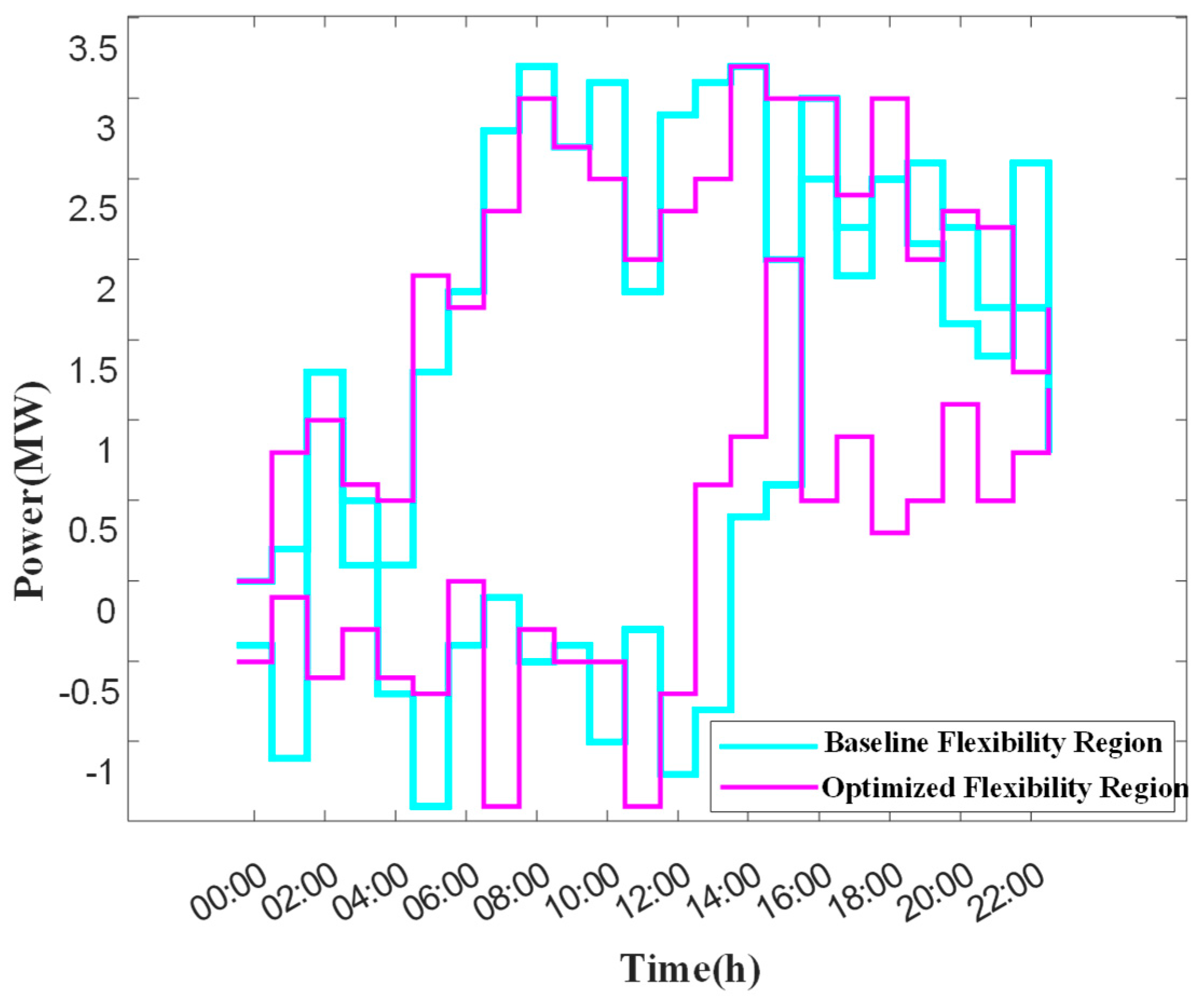
The power-feasible domains at the common coupling point before and after optimization in scenario 1 and scenario 2 are shown in
Figure 8 and
Figure 9, respectively. The blue area and the pink area in the figure are, respectively, the feasible domains of active power in each period before and after optimization, and the purple area is the crossover area before and after optimization.
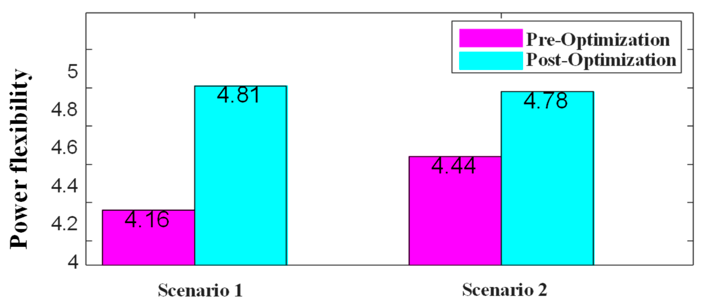
In order to intuitively analyze the results before and after the optimization of the active power flexibility at the common coupling point, the power flexibility of each period before and after the optimization in the two scenarios is summed up to obtain the results shown in
Figure 10.
The analysis results show that the proposed method improves the grid-connected power flexibility of the small-micro parks by 16% in scenario 1 and 7% in scenario 2.
This not only verifies that the method can fully release the power flexibility of distributed resources and significantly improve the grid-connected power flexibility of the small-micro parks. In addition, the research results also reveal the impact of the reactive power flexibility of the distributed resources on the grid-connected power flexibility of the small-micro parks.
All examples in this article are performed on the hardware environment device AMD Ryzen-7 8745H (Advanced Micro Devices, Inc., Santa Clara, CA, USA), and the solver Gurobi is called using the R2022a platform and the Yalmip toolbox (version: R20220407).
5. Conclusions
This paper proposes a small-micro parks’ network reconfiguration method for improving power flexibility. In order to solve the problem of the limited flexibility of distributed resources caused by network constraints, the power flow distribution in typical scenarios is optimized by network reconfiguration to improve grid-connected flexibility. Specifically, this paper establishes a two-stage adaptive robust optimization model to achieve the aggregate representation of grid-connected point flexibility and network reconfiguration strategy optimization, and effectively solves the model using column and constraint generation algorithms. The simulation analysis of the example shows that the optimization improves the grid-connected power flexibility of the small-micro parks and analyzes the reasons for the improvement of the additional flexibility of the grid-connected point in combination with specific scenarios.
The method proposed in this paper can be applied to various operation modes under the new power system, such as grid-connected distribution network, distribution, and micro-cooperative operation. Other types of flexibility, such as frequency regulation provided by microgrids to the outside world, also need further study.
