Article

Experimental Optimization, Scaling Up, and Characterization for Continuous Aragonite Synthesis from Lime Feedstock Using Magnesium Chloride as Chemical Inducer

by
Mohammad Ghaddaffi M. Noh
1,2,*,
Nor Yuliana Yuhana
2,
Mohammad Hafizuddin Hj Jumali
3,
Mohammad Syazwan Onn
1 and
Ruzilah Sanum
1
1
PETRONAS Research Sdn. Bhd, Lot 3288 & 3289, Off Jalan Ayer Itam, Kawasan Institusi Bangi, Kajang 43000, Selangor, Malaysia
2
Department of Chemical and Process Engineering, Faculty of Engineering & Built Environment, Universiti Kebangsaan Malaysia, Bangi 43600, Selangor, Malaysia
3
Department of Applied Physics, Universiti Kebangsaan Malaysia, Bangi 43600, Selangor, Malaysia
*
Author to whom correspondence should be addressed.
Processes 2025, 13(10), 3142; https://doi.org/10.3390/pr13103142
Submission received: 15 May 2025 / Revised: 30 July 2025 / Accepted: 21 August 2025 / Published: 30 September 2025

Abstract

The current state of the art research, and latest engineering technology application in the synthesis of the aragonite crystalline phase of calcium carbonate is presented here. Aragonite crystalline products are highly valuable in selected industries, such as medical and personal care, and in food additives using MgCl2 as a chemical inducer. The outcome of this literature review provides the outlook of the available research whitespace opportunity in optimizing the current process parameters and in ensuring that sustainable and economically feasible continuous production of aragonite products could be achieved. One of the major improvements proposed in this study is to investigate the methods of synthesizing aragonite crystalline particles using a continuous mineral carbonation reactor system and optimizing the operating parameters. An experimental design was established to identify all the main effects to maximize aragonite production. The three main effects investigated are the effect of feedstock or reactant concentration, the effect of reaction temperature, and the effect of reaction time towards aragonite yield in the final products synthesized. An optimized operating parameter for maximum aragonite yield at 95% purity was proposed at the reaction temperature T of 90 °C, reaction time t of 10 min, and feedstock ratio Mg-to-Ca of 0.4. Subsequently, the continuous reactor system was designed, operated, and tested for at least 50 h operation, where the lime CaO(s) feed was successfully converted into aragonite products with purity between 75 and 81%. The properties and quality of the aragonite produced were analytically characterized from the following laboratory methods which include the thermalgravimetric analysis, TGA; X-Ray Diffraction, XRD; scanning electron microscopy, SEM; and induction coupled plasma, ICP. TGA mass balance after decomposition suggests that 44% of the mass balance represents the weight of CO2 sequestered in the aragonite crystalline carbonates. Hence, the aragonite crystalline carbonates can be labeled as a green product which sequesters 0.44 kg of CO2 per 1 kg of precipitated aragonite products synthesized. Interestingly, SEM microscopy characterization results revealed that the aragonite precipitate has a physical morphology of needle-like shape with a good aspect ratio (length/diameter) AR of between 8.67 micron and 11.35 micron. The properties were found to be suitable for paper making fillers, medical, personal care, and food additive applications.

1. Introduction

The concept of utilizing carbon dioxide CO2 emissions as an industrial feedstock to produce sustainable green products has been explored by many since the beginning of the last century, but the extensive energy requirements and the high unit cost of production remained to be the biggest challenges faced by the chemical industry at large [1]. Various catalytic conversion pathways of CO2 have been reviewed by Aresta et al. [2] and Sakakura et al. [3] but most pathways consumed a considerable amount of energy [4] in the form of heating requirement, extensive usage of hydrogen as energy carrier feedstock, and, also, high compression requirements. Another pathway of utilizing CO2 is via the biological pathway, but this requires a considerably longer period of organic maturity to reach its goals and target volumes. Another route in consideration for utilizing CO2 is via mineral carbonation pathways [5,6], where the reaction is thermodynamically favorable, and takes place in low pressure aqueous reaction media; thus, no high energy penalty is required for first and second oxygen dissociation energy of CO2 during the chemical reaction process. Conversion of CO2 to calcium carbonate calcite products has been demonstrated up to commercial scale by many [7,8,9,10]. Both De Choudens-Sánchez et al. (2009) [11] and Park et al. (2008) [12] have successfully demonstrated the synthesis of aragonite, which is another crystalline morphology of calcium carbonate CaCO3, via the usage of chemicals such as magnesium chloride MgCl2 inducers and using a batch reactors setup.
This study attempts to synthesize aragonite crystals using a chemical inducer, such as magnesium chloride MgCl2, via a continuous reactor system and to optimize the parameters related to the production of aragonite by varying the studied parameters such as flow rate or reaction time, reaction temperature, and lime feed concentration. Finally, the aragonite synthesized from this study is recovered and characterized in terms of its physico-chemical properties, and is regarded as the most suitable filler material for the paper and plastic industries and useful high value additives for the biomedical industrial application.

2. Literature Review

Natural precipitation of calcium carbonate CaCO3 from a saturated solution of lime Ca(OH)2 and CO2 under standard chemical reaction conditions results in the rhombohedral and scalenohedral crystalline form of calcite [13]. However, the addition of magnesium ions to the crystallizing medium opens a whitespace of morphological possibilities. Aragonite crystals are metastable but are marginally more stable than vaterite. Aragonite exists naturally and is the main component of nacre and mollusk shells [14]. It is well established that magnesium exerts a significant influence on calcium carbonate crystallization and that aragonite typically crystallizes in preference to the thermodynamically stable polymorph calcite, when the magnesium Mg2+ concentration is sufficiently high [15]. It has been widely observed that, at high concentrations, magnesium ions Mg2+, are known to induce the synthesis of aragonite [16]. Various theories have been proposed to support this observation, namely the calcite poisoning model, the inhibition of calcite nucleation model, the adsorption of magnesium ions at the calcite growth site model, the distortion of the calcite lattice model, the change in the surface charge model, and, lastly, the kinetic problem of cation dewatering model as emphasized by Nancollas et al. [17]. However, the exact role that Mg2+ plays in the precipitation of aragonite, as opposed to calcite, is still widely debated by many researchers, but the most commonly expressed idea is that magnesium inhibits the growth of calcite and, therefore, allows aragonite phase to crystallize rapidly as pointed out by Bischoff, 1968 [18]; Bischoff and Fyfe, 1968 [19]; Berner, 1975 [20]; Fernández-Díaz et al., 1996 [21]; and a review work by De Choudens-Sánchez et al. [11]. Hence, the inhibition of calcite growth is generally attributed to “poisoning” of the growth sites on the calcite crystal faces by Mg2+ ions that are more strongly hydrated than the Ca2+ ions [22,23].
Pao-Chi Chen et al. (1997) [24] and Christoffersen et al. (1990) [25] studied the polymorphism of calcium carbonate crystal by introducing CO2 gas through a gas sparger, or a double-tube gas injection nozzle, into a pH-stat crystallizer containing calcium chloride CaCl2 solution. Several operating variables were investigated, and the pH of solution and calcium ion Ca2+ concentration were the important factors that affected the formation of polymorphs of calcium carbonate. It was found that, at ambient temperature, either calcite or vaterite is the major product, depending on the pH and calcium ion Ca2+ concentrations. Then, the same crystallization system was employed to study the growth kinetics of calcite crystals, using a double-tube gas injection nozzle instead of a gas sparger, which cannot be used to suppress nucleation, to introduce the CO2 gas into the crystallizer. The growth rates of calcite seeds increased with increasing supersaturation and crystal size. In conclusion, the polymorphs and growth rate of calcium carbonate were proven to be controllable in a gas–liquid–solid reactive crystallizer, using a pH-stat operation mode.
Additionally, Fiona C Meldrum et al. (2001) [15] investigated the morphological influence of magnesium and organic additives on the precipitation of calcite. Calcium carbonate was precipitated from saturated solutions of calcium bicarbonate in the presence of magnesium and organic additives in order to investigate the effect of Mg-incorporation on calcite morphologies. The action of organic additives in Mg-free solutions was reported to be highly specific, producing elongated single calcite crystals. A much wider range of calcite morphologies was observed in the presence of both magnesium and organic additives, and a transition from single crystal to aggregates occurred by increasing the magnesium concentrations. The polycrystalline aggregates had morphologies ranging from dumbbells to spheres and occluded up to about 22% MgCO3. The experiments suggest that Mg2+ ions act in combination with organic additives affected by calcite morphologies by mechanisms such as adsorption on specific crystal faces which inhibit growth, and by altering the calcite nucleation and growth processes.
In another development, Zeshan Hu and Yulin Deng (2004) [26] successfully synthesized needle-like aragonite from calcium chloride and sparingly soluble magnesium carbonate. It was established that high synthesis temperature T is favorable to both aragonite fraction and higher aspect ratio, along with high pH conditions, and is beneficial for the formation of aragonite. Interestingly, aging results in the transformation of aragonite back into calcite if calcite exists in the suspension. Further results revealed that for an aragonite suspension without calcite and with Mg2+ presence, aging will decrease the needle length and the aspect ratio of aragonite particles. In terms of aragonite yield, Wang, L et al. [27] concluded that as the concentration of Mg2+ ions is increased in the reactant feedstock, yield of intermittent complex Mg-calcite decreases, and yield of aragonite increases concomitantly; as such, when the concentration of MgCl2 is continuously increased to 75 mol %, no Mg-calcite is produced, and only single-phase aragonite is obtained. However, the aspect ratio of aragonite decreases with an increase in the Mg/Ca ratio. More recently, based on thermodynamic considerations, Sun et al. (2015) [28] argued that the inhibition of calcite nucleation from the inclusion of Mg2+ is due to an increase in the surface energies and, interestingly, it was reported that for aragonite precipitation to occur in seawater, the following conditions have to be achieved: Mg: Ca ratio > 2 and supersaturation levels > 18 are required.
Utilizing amorphous calcium carbonate ACC as lower value feedstock starting material, Satoshi Kajiyama et at. (2014) [29] successfully synthesized aragonite nanorods in calcium carbonate/polymer hybrids formed through self-organization processes from amorphous calcium carbonate solution. For the formation of calcium carbonate (CaCO3) phase transformation to take place, polymer hybrids, spin-coated and annealed films of poly(vinyl alcohol) (PVA) that function as polymer matrices, are soaked in aqueous colloidal solutions dispersing ACC stabilized by poly(acrylic acid) (PAA). Aragonite crystals start to form inside the PVA matrix which contains PVA crystallites, inducing aragonite nucleation. Nanostructured hybrids composed of calcite thin films, consisting of nanoparticles and assembled aragonite nanorods, are formed in the matrices of PVA. In another development, Chilakala Ramakrishna (2015) [30] successfully prepared needle-like aragonite-precipitated calcium carbonate (PCC) by carbonation method and claimed it to be the first time aragonite was synthesized from dolomite starting material in the lab via a simple carbonation method. In this study, calcium is extracted from natural dolomite. Aragonite needles with width of 3 microns and 40 microns length were formed by feeding 50 mL/sec CO2 gas into MgCl2+. Ca(OH)2 solution from dolomite feedstocks at 80 °C after a 3 h carbonation process without addition of additives. Aragonite formation increased as the carbonization temperature increased up to 80 °C where needle like aragonites are formed at 80 °C with a 50 cc CO2 flow rate.
The effect of physical conditions has also been widely studied in the synthesis of aragonite. These conditions include temperature, pH of the reaction solution, and supersaturation. The hypothesis that temperature played an important role in the precipitation of aragonite and calcite was supported very early in the last century by a number of prominent research work performed by Meigen (1901) [31], Linck (1903) [32], Johnston et al. (1916) [33], Kohlschütter & Egg (1925) [34], Saylor (1927) [35], Faivre (1946) [36], Togari and Togari (1955) [37], and Zeller and Wray (1956) [38] as reported in a review work by Brian Jones [39]. More detailed experimentations on the more precise temperature range resulting in aragonite formation were conducted by Suganuma (1928) [40], who discovered that calcite phases are usually formed at <50 °C, while aragonite phases are formed if temperature T > 50 °C. Goto (1961) [41] suggested that aragonite was formed when T > 60 °C, while Roques and Girou (1974) [42] experimentally demonstrated that the CaCO3 phase transitioned from vaterite to calcite and, finally, to aragonite as temperature T is increased. Chakrabarty and Mahapatra (1999) [43] argued that vaterite is formed if T < 15 °C, calcite is formed at room T, and aragonite is formed when T > 70 °C. Supporting this argument, Nebel and Epple (2008) [44] proposed from their work that vaterite precipitates at low T, calcite at room T, and aragonite at high T. In addition to the above, Chen and Xiang (2009) [45] suggested that vaterite is formed at 30–40 °C and that at a temperature of 50 °C increased aragonite precipitation will occur. In another study, Tai and Chen (1998) [46] used their experimental findings to argue that CaCO3 polymorph precipitation was controlled by various parameters, including pH with precipitation of aragonite occurring if pH = 11 when the experimental conditions were at room temperature.
In order to continuously synthesize needle-like aragonite, some inorganic additives have also been studied. In the effort of utilizing naturally occurring feedstock, Zeshan Hu et al. [47] reported needle-like aragonite synthesized from a reverse reaction of the dissolution of ground calcium carbonate GCC in magnesium sulfate solution at 70 °C, resulting in a needle-like aragonite of 20 micron in length. Based on experiments conducted by Matsumoto et al. (2010) [48], CO2/NH3 microbubbles were passed through a reagent mixture to establish the following relationships where aragonite phase is formed if pH is set between 9.7 and 10.5. However, it was also noted that, with a pH of 9.7, the rate of aragonite crystallization accelerated if the CO2/NH3 molar ratio and average bubble size of the CO2 gas were decreased. Furthering the research on aragonite, Gomez-Villalba LS et al. [49] successfully demonstrated the formation of aragonite phase using an alcoholic colloidal solution of Ca(OH)2 nanocrystals exposed to high relative humidity RH at different exposure times and at room temperature. The aragonite formed a rosette-like structures at 90% relative humidity RH and fiber-like structures at 75% RH during the carbonation process of lime Ca(OH)2 nanocrystals.
Laifeng Wang et al. [27] successfully synthesized uniform aragonite particles directly in the presence of urea at elevated temperature, under restricted experimental conditions, by aging solutions of calcium salts in the presence of urea at 90 °C. Peiliang Shen (2022) [50] developed an innovative wet carbonation process to produce aragonite whisker-rich materials (AWM) from cement and simulated flue gas, enhancing cement properties and capturing CO2. Needle-like aragonite whiskers (10- to 30-micron length, and 0.5- to 2-micron diameter) were synthesized rapidly at 80 °C with 0.05 M/L MgCl2. High Ca2+ concentration and Mg2+/Ca2+ molar ratio > 0.12 favored aragonite formation. Mixing AWM with cement significantly improved mechanical performance and reduced CO2 emissions by 25.3%. Xiaolei Ding et al. (2024) [51] successfully demonstrated the preparation of aragonite from calcium carbonate via wet carbonation method to improve properties of steel slag building materials. This work successfully validates the fact that the formation of needle-shaped aragonite can be firmly regulated by the addition of magnesium hydroxide and magnesium chloride as crystalline control agents. Mahmut Altiner et al. [52] were also successful in developing production method and characterization of synthetic aragonite prepared from dolomite by eco-friendly leaching–carbonation process as well, in which pure aragonite crystals were successfully synthesized at temperatures between 40 and 70 °C, with a CO2 flow rate of 3.00 L/min and a stirring speed of 750 rpm. The reaction time decreased with an increase in the CO2 flow rate.
A detailed crystal growth mechanism of green aragonite is depicted in Figure 1 below, as proposed by Habte et al. [53]. At the start of reaction, the aqueous solution before carbonation mostly comprises a co-existence of Ca(OH)2 and Mg(OH)2. Carbonation happens as soon as Ca2+ ions encounters CO32− ions to form nuclei of calcite particles in which, due to natural interchangeability Mg2+ ions, it was able to replace Ca2+ ions of calcite to form Mg-doped calcite intermittent complexes [54]. However, increasing Mg2+ concentration decreases the yield of Mg-doped calcite while simultaneously increasing aragonite crystalline growth. In the context of coordination chemistry, Ca2+ and Mg2+ with an effective ionic radius of 1.00 and 0.72 Å, respectively, forms a six-fold coordination complex (i.e., Mg2+ is 28% smaller). In this particular aqueous reaction system, where Ca2+ and Mg2+ forms a six-fold coordination complex, a tenacious hydration layer is formed on the surface of the developing crystal resulting in the adsorption of Mg2+, and thereby curtailing the nucleation rate of calcite crystals [29].
Carbonation is a relatively environmentally friendly and potentially carbon neutral process. Lime Ca(OH)2 is commonly prepared by heating limestone (CaCO3), which is accompanied by the release of CO2 as depicted by the three general Equations (1)–(3) below.
CaCO3 → CaO + CO2 (calcination of natural limestone)
CaO + H2O → Ca(OH)2 (slaking)
Ca(OH)2 + CO2 → CaCO3(s) + H2O(aq)
For the synthesis of aragonite using magnesium chloride MgCl2 as a chemical inducer, the governing Equations (4)–(12) is proposed as the reaction steps for the CO2 carbonation process, hydration of carbon dioxide, the ionization of calcium hydroxide, precipitation, and formation of aragonite lattice.
Hydration of carbon dioxide and the Ionization of calcium hydroxide:
Ca(OH)2(s) + MgCl2(aq) → Mg(OH)2(s) + CaCl2(aq)
Ca(Cl)2(aq) + H2CO3(aq) + Mg(OH)2(s) → CaCO3(s) + MgCl2(aq) + 2H2O
CO2 absorption:
CO2(g) → CO2(aq)
Hydration of dissolved CO2:
CO2(aq) + H2O ←→ H2CO3(aq)
Reaction of hydroxyl ions with dissolved CO2 for high pH solution:
CO2(aq) + OH(aq) ←→ HCO3(aq)
HCO3(aq) + OH(aq) → CO32−(aq) + H2O
Dissociation of calcium hydroxide:
Ca(OH)2(aq) → Ca2+ + 2OH(aq)
Ca(OH)2(s) + Mg2+ + 2Cl(aq) → Mg(OH)2(s) + Ca2+(aq) + 2Cl(aq)
Precipitation:
Ca(Cl)2(aq) + CO32− (aq) + H2O+ Mg(OH)2(s) → CaCO3(s) + MgCl2 (aq) + 2H2O
Supersaturation (SI) of the solution with respect to calcium carbonate:
SI = [(Ca2+) (CO32−)]/Ksp > 1
Ca2+ + CO32− → CaCO3 (nuclei)
CaCO3 (nuclei) → CaCO3 (Aragonite)

3. Method

3.1. Experimental Setup and Procedure Using Lab Scale Glass Reactor

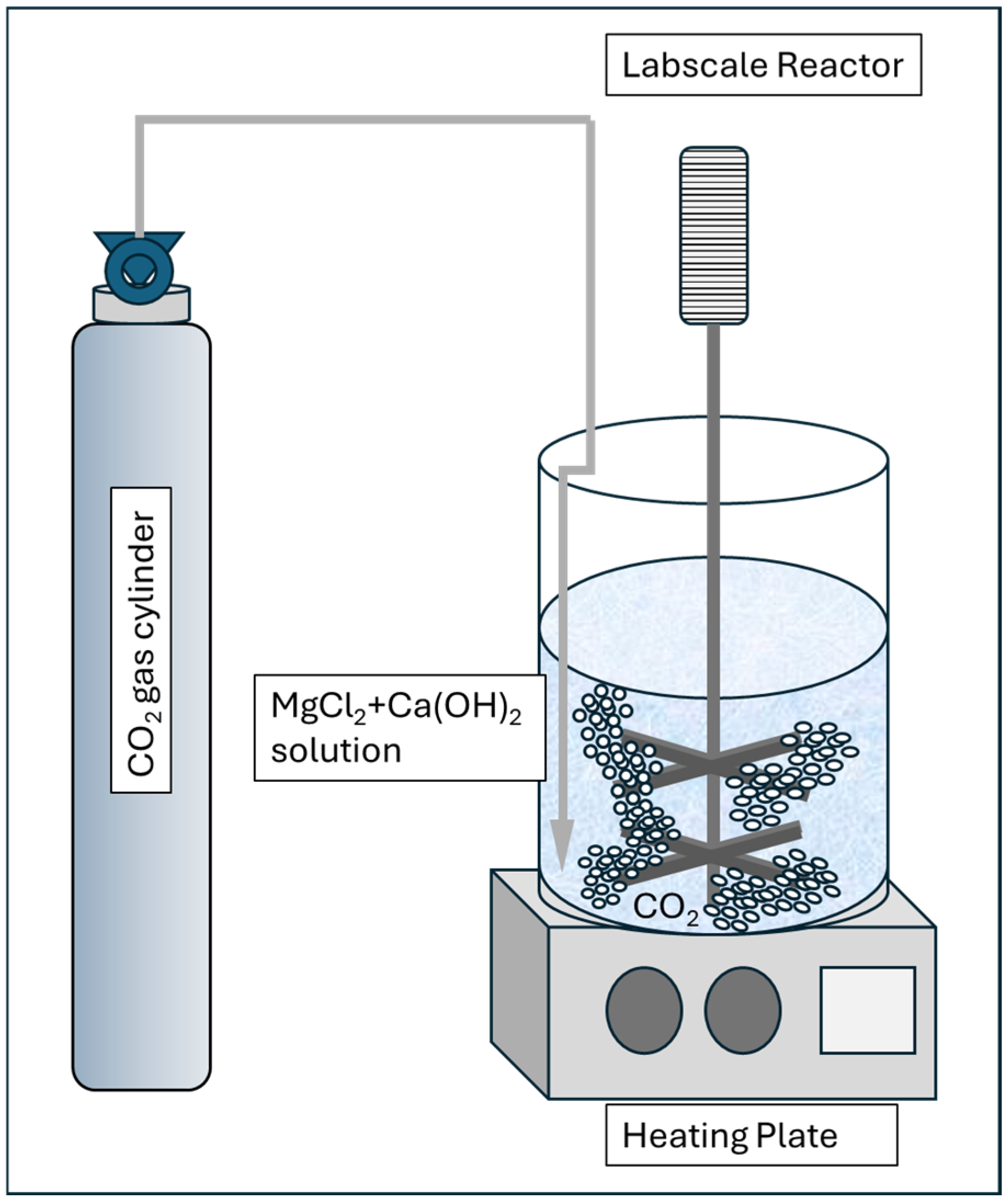
This laboratory setup is to investigate and optimize the effect of solution temperature T, Mg-to-Ca Ratio, and reaction time in order to maximize aragonite yield. The setup consists of a 1 L glass reactor, mechanical stirrer, heating plate, and temperature controller, and a CO2 gas bubbling system and a lime solution with magnesium chloride inducer prepared in accordance with the procedure below. The visual of the setup is shown in Figure 2 below.

3.2. Synthesis of Aragonite

3.2.1. Laboratory Procedure

  • Solution of MgCl2 and Ca(OH)2 mixture with specific concentrations as demonstrated by Park et al. (2008) [12] and Shen et al. (2022) [50] was heated until reaching the target temperature between 40 and 90 °C and stirred at 250 rpm [43,44,45].
    • A total of 1 g of Calcium Hydroxide powder Ca(OH)2 laboratory grade is stirred into 1 L of double distilled water until a stable milk of lime solution is formed.
    • Add 2.33 g of anhydrous magnesium chloride into the milk of lime solution slowly until evenly mixed and no further solid clumping observed.
    • The mixture is continuously stirred for another 1 min.
  • CO2 feed gas with constant flowrate 300 mL/min [30,52] is bubbled into the reactor at different reaction time range (1–10 min) [52].
  • Allow the solution to react in accordance with the reaction time requirement (1–10 min) until solution becomes clear and mineral precipitates are formed.
  • Stop the stirring and let the precipitation settle down. Siphon out the clear liquid until a third of the solution volume is left. Vacuum filter the liquid and solid precipitate mixture.
  • The solid sample is analyzed using X-Ray Diffraction, XRD, particle size analyzer, PSA, and the spent reactant is analyzed using Induction Coupled Plasma, ICP, method.

3.2.2. Analytical Equipment Settings

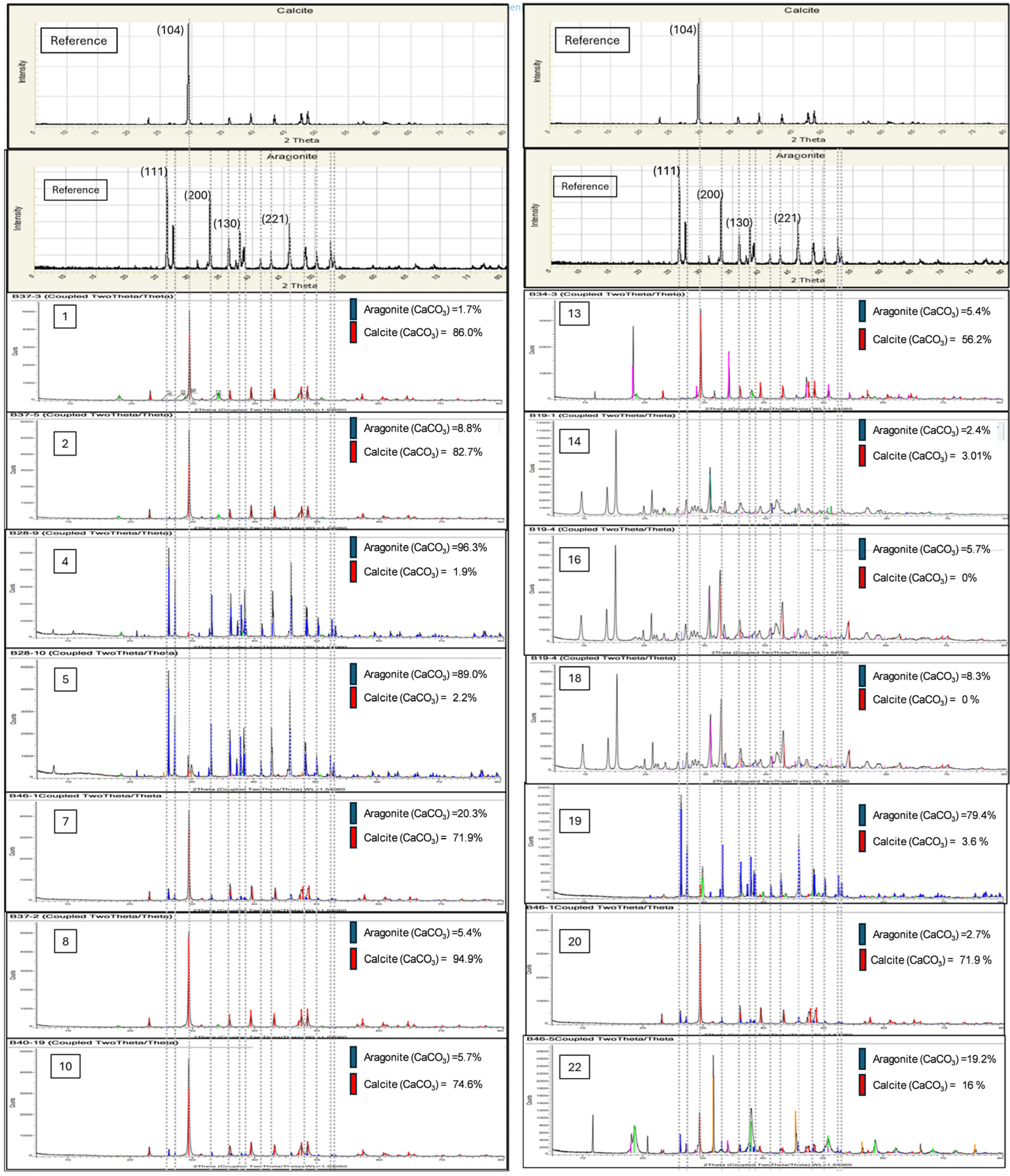
The primary analysis in this study, which was the XRD analysis, was conducted using the model Bruker D8 Advance (Bruker Physik-AG, Karlsruhe, Germany)with a copper tube anode material. This one-dimensional fast Lynk-Eye detection is set with the °2Θ range between 5° and 80°, a step size of 0.025°, and a step duration of 0.3 sec/step. All the collected diffractogram was analyzed using the software provided, Diffrac Plus EVA v.7.0. The concentration of both aragonite and calcite in the sample is determined by quantitative analyses based on the following established method as reported by Department of Geology, University of Georgia [46]. Expanding the basis, or quantitative analyses, here, it was established that aragonite phase has the greatest peak (111) at °2Θ = 31, and other prominent peaks (200) at °2Θ = 36, (130) at °2Θ = 38, and, most importantly, (221) at °2Θ = 45 as a secondary signature indicator of the presence and abundance of aragonite as a monocrystalline phase of calcium carbonate. On the other hand, calcite has a prominent peak of (104) at °2Θ = 34 to the right of aragonite’s (111) peak. Unfortunately, the aragonite peak begins to subside when aragonite content goes below 25% and quantitative detection can become misleading at times. The solution to this problem is to use the aragonite (221) peak as an alternative indicator of the abundance of aragonite and perform a comparative ratio with the calcite (104) peak.
In addition to the XRD analysis, the particle size analysis, PSA, was carried out using the Malvern Mastersizer 3000E Particle Size Analyzer (Malvern Panalytical, Malvern, UK) to determine the particle size distribution using the wet method. The ionic concentration in the spent liquid reactant was analyzed using the equipment, ICP-OES Avio 550 by Perkin Elmer (Waltham, MA, USA), and the APHA Method 3120: Standard Methods for the Examination of Water and Wastewater.

3.3. Design of Experiment

A Two Level Full Factorial Design was chosen as the initial design of experiment methodology to establish the main factors and effects. The test consists of twenty-four experimental runs, three parameters, and two levels (high and low) with three replicates. The main factors or parameters under investigation are based on the following experiments conducted by [42,43,44,52]:
  • Reaction temperature, T: 40–90 °C [42,43,44].
  • Mg-to-Ca mass ratio, r: 0.2–0.4 [50,54].
  • Reaction time, t: 1–10 min [52].
The 24 experimental runs are randomized by the software Design Expert version 25.0 as tabulated in Table 1 below to cover the three main factors understudied with the response as percentage of aragonite crystalline phase detected within the precipitation, aragonite yield %.

3.4. Results

The total collected diffractograms analyzed using the software provided, Diffrac Plus EVA, are shown in Figure 3 below. Diffractograms of samples not shown in Figure 3 are those found to have insignificant percentage of aragonite phase and having similar diffractogram pattern with sample#1.
The results, or aragonite percentage yield, are compiled and tabulated in Table 1 above for the respective factors under investigation. Response of aragonite percentage yield was recorded to be between 0% and 96.3% for the various randomized experimental runs.
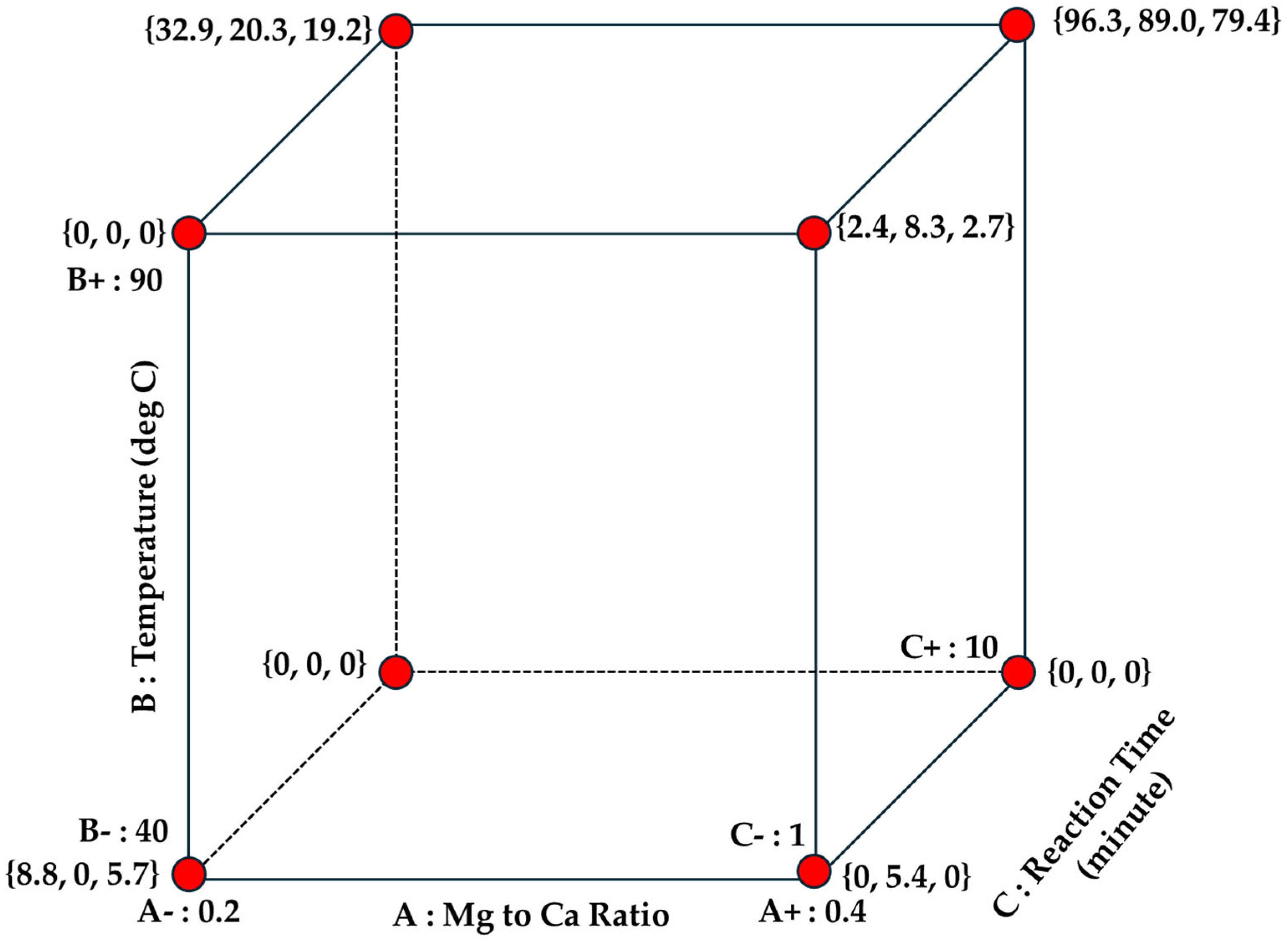
The standard runs and the response are graphically represented in a 3D factors interaction cube to provide better visualization of the individual single factor responses, two-way interaction factor responses, and three-way factor interaction responses as provided in Figure 4 below.
The positive trends of the aragonite yield responses are mainly located between the edges associated with both the high reaction time side (10 min) and high reaction temperature (T = 90 °C) side. This provided trending results that both higher temperature and reaction temperature affect aragonite yield in a positive manner. All the points associated with the bottom section of the cube have low aragonite yield which brings us to another general trend that lower reaction temperature (T = 40 °C) impacts negatively on aragonite yield.
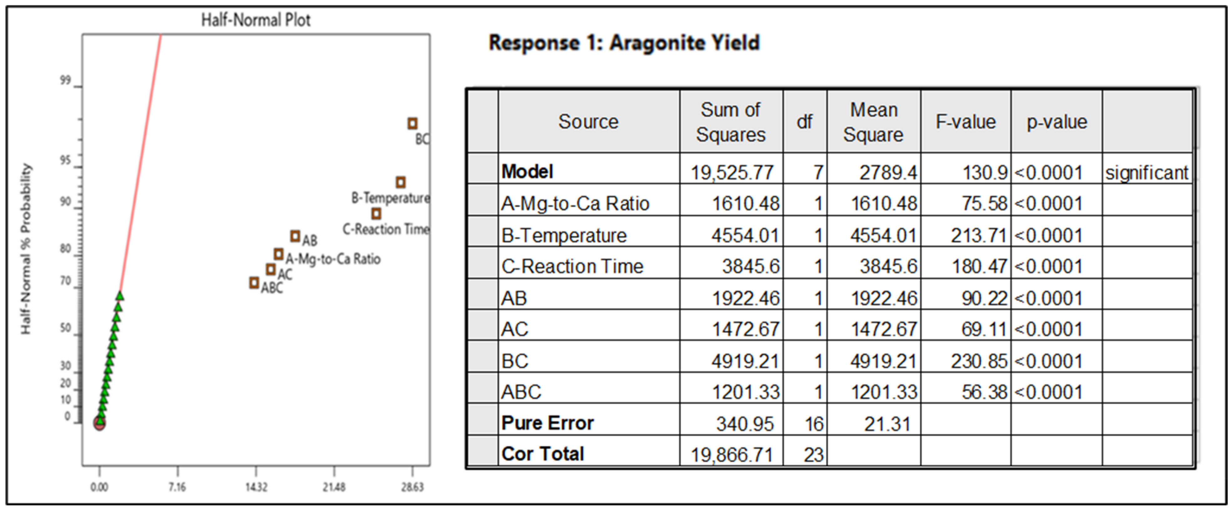
The responses are tabulated in a half normal plot by Design Expert as in Figure 5 below.
Based on the p-value calculated for the specific response versus the general population, factor A—Mg-to-Ca Ratio, factor B—Temperature, and factor C—Reaction Time have significant effect on aragonite yield, and a combination of all three factors ABC contribute positively to the aragonite yield. Main factors contributing positively to the aragonite yield with the highest effect are B—temperature (with F-value of 231) and C—Reaction Time (with F-value of 180), whereby both two-way interaction factors BC provided the highest effect for aragonite yield (with F value of 230). Ratio of Mg-to-Ca, or Factor A, is still a significant factor which contributes to aragonite yield, but the nominal effect of it is much less than Temperature B and Reaction Time C with a F value of only 75. Hence, from the randomized run conducted, it is proposed that the optimization of the aragonite production will focus on, firstly, Factor B—Temperature and C—Reaction Time while optimizing Factor A—Ratio of Mg-to-Ca, which involved the usage of magnesium chloride MgCl2 as the aragonite inducer or chemical agent that is taken as a trade-off between maximizing aragonite yield and minimizing cost of MgCl2 in this process.
Hence, the general equation is maintained as in Equation (13), below, as all individual and interaction factors have significant effects contributing towards aragonite yield Y:
Y   =   α 1 A + α 2 B + α 3 C + α 4 A B + α 5 B C + α 6 A C + α 7 A B C
where
α 1 , α 2 , α 3 , are factor constants for the individual factors A, B, C;
α 4 , α 5 , α 6 are factor constants for the two-way interaction factors AB, AC, BC;
and α 7 is a factor constant for the three-way interaction factor ABC;
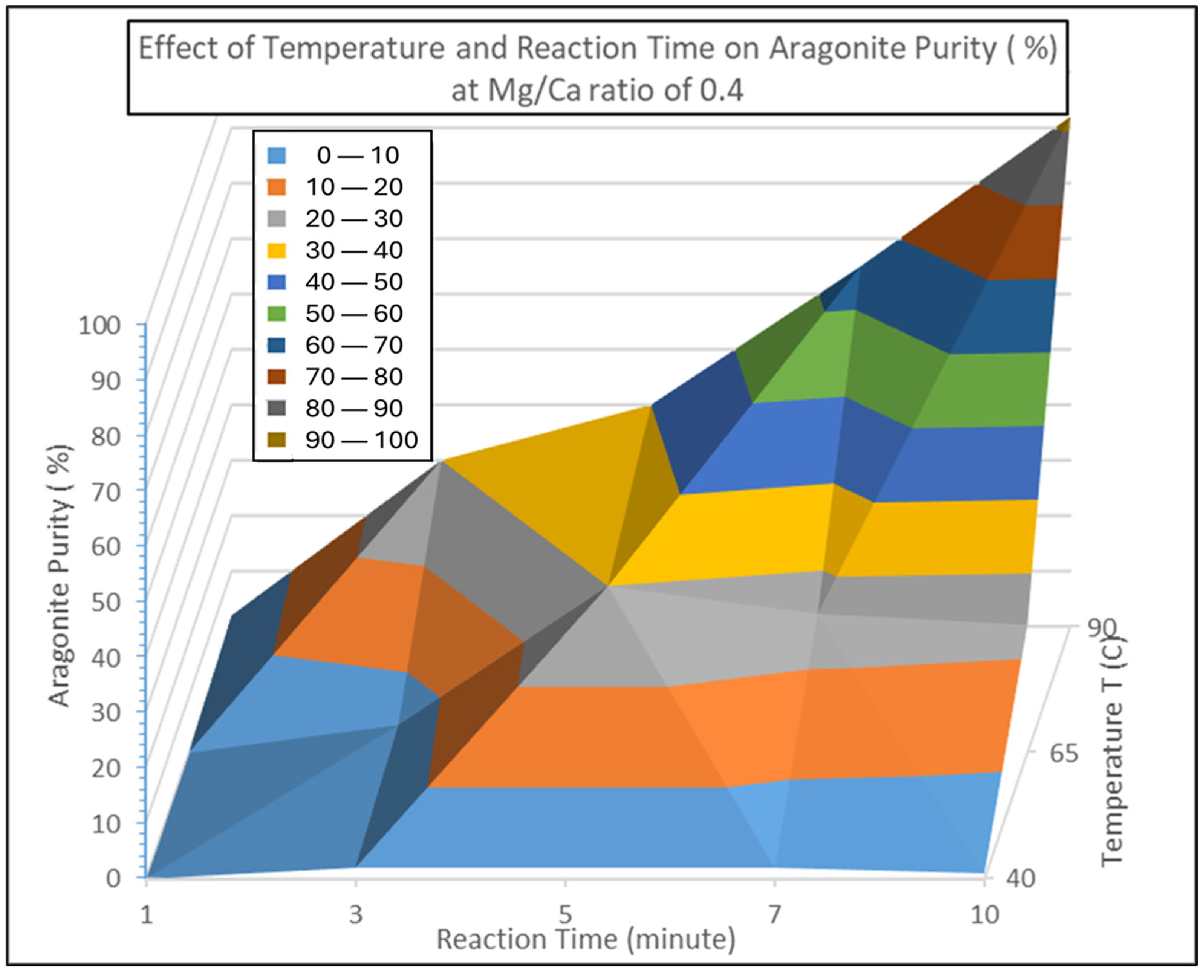
The experimental runs were extended to produce a surface response contour which includes the additional points for reaction time and temperature which are the major, or main, effects for aragonite yield as proposed in the equation above at the conditions of Mg/Ca ratio of 0.4. The additional experimental points included to finalize the yield contour are Reaction Temperature T at 65 °C and Reaction Time of 3 min, 5 min, and 7 min. The full plot for the yield, or aragonite purity at ratio of Mg/Ca = 0.4, is shown in Figure 6 below.
The contour reaffirms the main effect tests conducted earlier, reported in Table 1, in which both factors B—temperature and C—reaction time and the two-way interaction—BC were the main factors where the definitive aragonite yield response was closely related to the increased reaction time from 1 min to 10 min at temperature of 90 °C. Hence, the simplified model for the aragonite yield reaction can be simplified as in Equation (14):
Y   =   α 2 B + α 3 C + α 5 B C
where, at T = 90 °C and ratio of feedstock Mg/Ca = 0.4, α 2 , α 3 are constants for the individual factors A, B and α 5 are constants for the two-way interaction factors BC.

3.5. Optimization

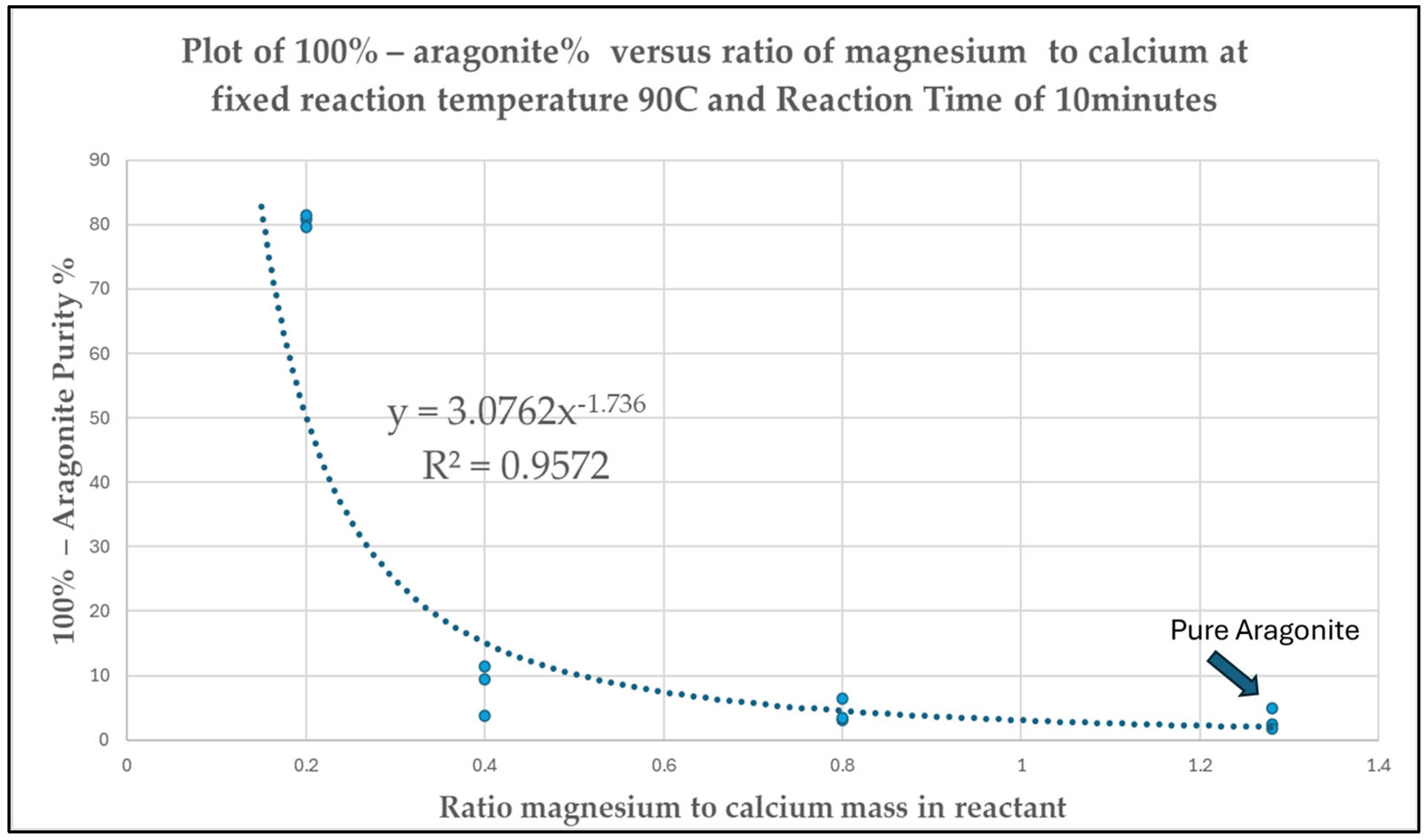
An additional experimental run was proposed and conducted to investigate and optimize the effect on aragonite yield by varying Mg-to-Ca ratios between 0.2 and 1.28 while fixing reaction time at 10 min and temperature to 90 °C based on the identified significant main factors established in Figure 4 and Figure 5 above. The results are presented in Figure 7 below.
The percentage non-aragonite from the reaction is plotted against the mass ratios of magnesium over calcium in the reactant Mg-to-Ca ratios between 0.2 and 1.28 with temperature fixed at 90 °C and reaction time maintained at 10 min. The mathematical trending follows a negative power relationship given by the equation below:
Occurrence of non-aragonite phase (100% − Aragonite Purity%), Y
= 3.0762 × (Ratio of magnesium-to-calcium)−1.736
= 3.0762 × ([Mg2+]/[Ca2+])−1.736
The percentage of non-aragonite phase occurrence decreases dramatically between Mg/Ca ratio of 0.2 and 0.4 from an average of 80.7% to 8.23% and ultimately in the low ranges of 8.23% to 3.10% average when ratio of Mg/Ca > 0.4. Hence, it can also be said that the purity of aragonite crystalline phase is higher than 91.77% when the ratio of Mg/Ca in the reactant is 0.4 or higher.
The optimization of Mg-to-Ca ratios will have to consider the trade-off between treat rate of magnesium chloride MgCl2 as a chemical inducer versus percentage yield of aragonite. Maintaining aragonite purity to be more than 91.77%, the process conditions for the continuous run can be carried out anywhere between Mg-to-Ca ratios of 0.4 and 1.28. In order to minimize the cost associated with magnesium chloride MgCl2 usage, the ratio of magnesium to calcium or Mg-to-Ca can be fixed at 0.4.

3.6. Losses of Chemical Inducer MgCl2 During Recycling

3.6.1. Method

The chemical inducers used are recycled each time a new cycle of reaction takes place. The reacted products are precipitates of calcium carbonate aragonite phase solids and Mg2+ and Cl ions dissolved in process water. The precipitates are vacuum-filtered and dried to recover the solids while the liquid ionic reactants MgCl2(aq) are recovered for the next round reactions. The spent aqueous solutions recovered are tested for Mg2+ and Cl ion concentrations using the induction coupled plasma ICP method after each test to find the percentage concentration losses after each cycle of reaction.

3.6.2. Losses

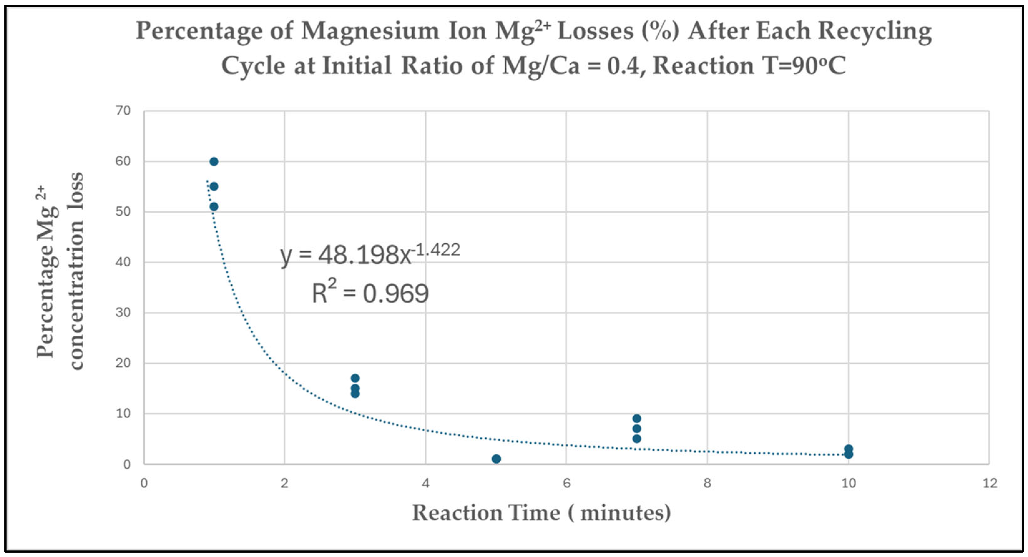
The experimental results and trending losses related to the chemical inducer magnesium chloride MgCl2 are presented in Figure 8 below. The losses drastically reduced as reaction time increased from 1 min to 10 min in a negative exponential trend. High losses of MgCl2 occur during a shorter reaction time of 1 min where more than 50% MgCl2 concentration loss was recorded. When the reaction time is increased to 3 min or longer, the concentration loss drastically reduced to somewhere between 15% and 2% concentration of magnesium chloride [MgCl2]. Extending the reaction time to 10 min, concentration loss of magnesium ions Mg2+ was, finally, contained at an average of 2% per reaction cycle when reaction operating condition is at 90 °C. This operating condition of having reaction time at 10 min was chosen to become the basis of the operating condition for the performance run using the continuous reactor.

3.6.3. Optimized Reaction Parameters

Henceforth, the finalized operating conditions of aragonite yield are proposed to be at temperature of 90 °C, reaction time of 10 min, and application of MgCl2 chemical inducer Mg/Ca ratio of 0.4 to produce aragonite with >95% purity and losses of MgCl2 anticipated to be between 2 and 5% within each reaction cycle.

3.7. Performance Run Using Continuous Reactor System

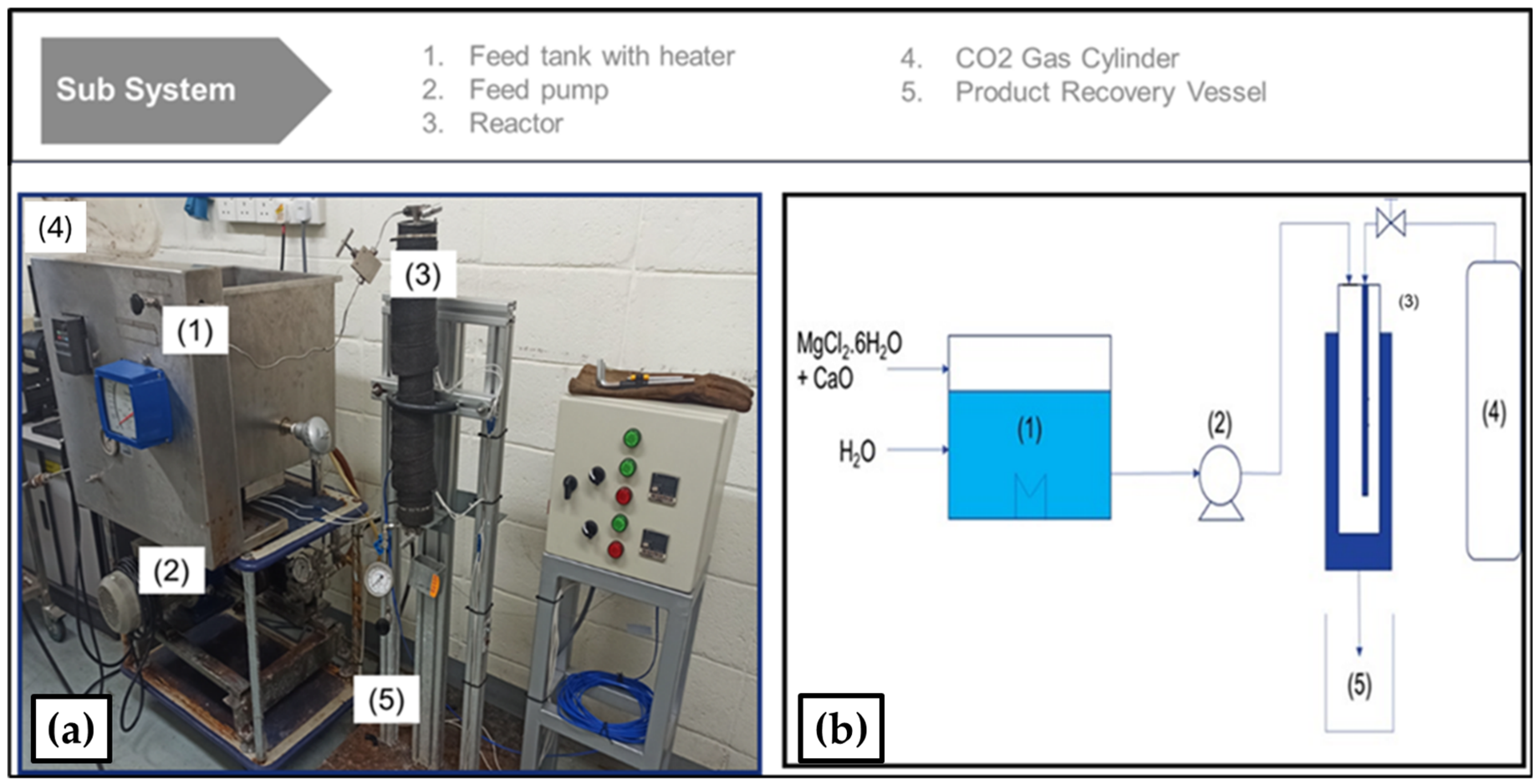
The performance run was conducted using a continuous flow mineral carbonation reactor apparatus. The schematics of the laboratory proof-of-concept reactor are also shown in Figure 9 below. The apparatus’ main components [55] include the following sub systems in its assembly:
  • Plunger type pump, motor driver, and speed controller.
  • Inlet to reactor liquid flow meter and pressure gauge.
  • Feedstock tank.
  • An 800 mL high pressure tubular reactor with inlet flow valve, and an outflow backpressure regulator with pressure indicator.
The continuous production of aragonite precipitates was conducted with the conditions proposed in Section 3.6.3. A minimum of 12 successful repetitive experiment runs were completed in succession to test repeatability and robustness, and to accumulate sufficient amount of solid precipitate samples for the various analytical test requirements. Unfortunately, some of the results for continuous runs had to be discarded due to technical errors and difficulties encountered throughout the tests such as disruptions of high-pressure liquid pumping, overpressure supply of CO2, and irregularities in feedstock temperature.

4. Physico-Chemical Characterization

The physico-chemical characteristics of the solid precipitate were carried out with the following analytical test methods:
  • Induction coupled plasma ICP for metal ion presence and concentrations.
  • X-Ray diffraction, XRD, to identify the crystalline morphology of the calcium carbonate precipitates.
  • Particle Size Distribution, PSD, to precipitate particle size distribution.
  • FESEM–imaging of crystalline structure.
  • Thermal Gravimetric Analysis, TGA, to characterize thermal decomposition of the crystalline precipitate.

4.1. Induction Couple Plasma ICP Analysis

A total number of 13 experimental runs were successfully completed using the experimental conditions proposed for the optimized continuous aragonite production. The solid precipitates from the synthesis are recovered by vacuum filtration, and these individual samples underwent an acid digestion procedure to dissolve the solid into ions of diluted concentrations. The freshly dissolved solid precipitation reactant and the spent, or reacted, liquid were analyzed using the equipment, ICP-OES Avio 550 by Perkin Elmer, using established in-house methods adopted from the APHA Method 3120: Standard Methods for the Examination of Water and Wastewater. The results are tabulated in Table 2 below.
Results obtained in Table 2 suggest that the proposed optimized operating conditions are robust in terms of repeatability and stabilizing magnesium ion losses, or seepage, into the solid precipitates at an average rate of 4.26% with a standard deviation of 0.95%

4.2. X-Ray Diffractogram XRD

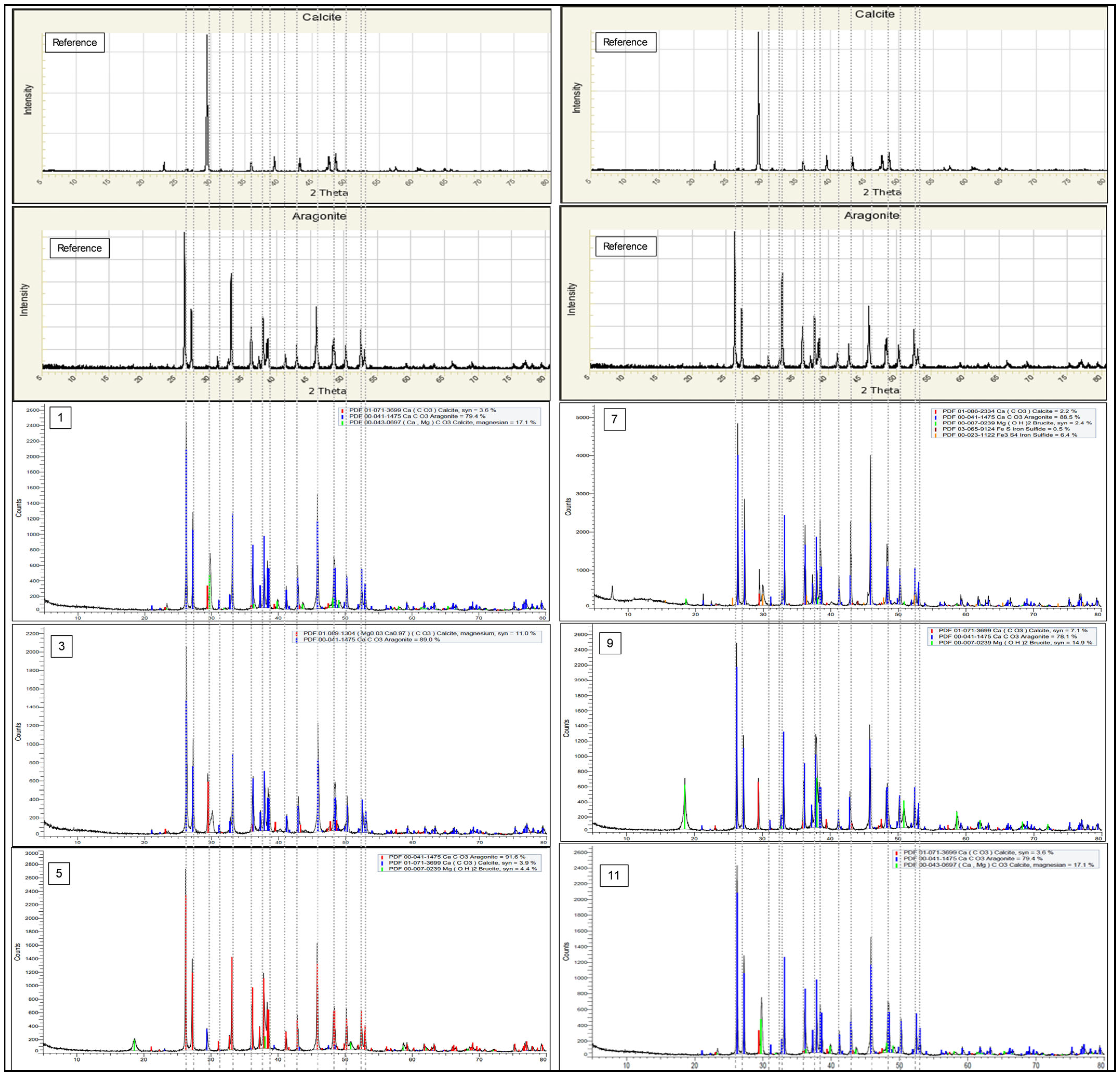
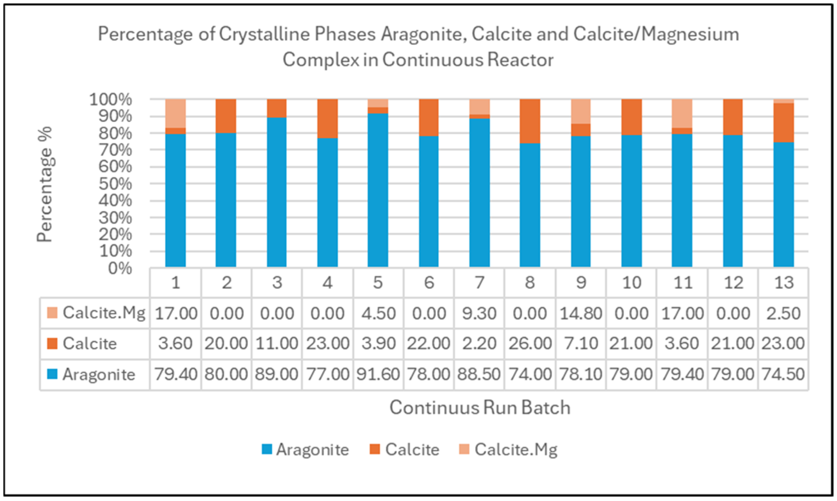
All the collected diffractograms in this continuous run of 13 batches were analyzed using the same software and methodology applied during the earlier optimization phase, Diffrac Plus EVA. The crystalline phase diffractogram and analysis obtained from Diffrac Plus EVA are tabulated in Figure 10. In terms of robustness and stability, the relative composition of crystalline phase aragonite, calcite, and dolomite from the continuous reactor system were compared for 13 back-to-back runs and subsequently tabulated in Figure 11.
XRD analysis indicates that CaCO3 in the product consists of aragonite phase crystalline with population average of 80.58% and a standard deviation of 5.328. This is lower than the results obtained during the optimization phase at approximately 95% aragonite purity. This reduction in aragonite purity or yield may be due to the following reasons:
  • Insufficient contact time between the CO2 gas and the reactant injected into the reactor resulting in net reduction in reaction time to be shorter than 10 min.
  • Insufficient heating lines which produced uneven temperature gradient throughout the different sections of the continuous reactor, thus resulting in the effective average real time temperature to be lower than the 90 °C setting.
  • Incoming reactant flow rate and product outflow rate affected by the inaccuracies of the manual liquid level controller settings resulting in constant variation in exposure time of the reactant to the pressurized CO2 gas.
  • Product recovered has been contaminated by the residue precipitation during the initial phase of reactor start up where temperature ramp up was still in progress or remnants of precipitation from the previous run interacted with the current reaction cycle.

4.3. Particle Size Distribution PSD

The particle size distribution analysis was carried out using the Malvern Mastersizer 3000 using wet method. PSD results indicate that the average particle size D50 achieved is 9.61 micron. The results are tabulated in Table 3 and Figure 12 below.
The ability to control shape, size, and biocompatibility, as demonstrated by Marta d’Amora et al. and Mohammad Yousef Memar et al. [56,57], provided the avenue for calcite crystals to be very useful for a wide range of applications, such as personal care, biomedical applications, and filler. M G M Noh et al. [55] reported that the particle size of precipitates of PCC in a continuous reactor system can be controlled on the fly by manipulating the feed solution injection rate and feed residence time, where the milk of lime is used as a feed solution and lime solution to produce particle size variations in PCC in the range of 6 to 10 micron for P50 and P90 particle size distributions suitable for multiple applications in the industry including medical, paper making, rubber, gloves, and plastic filler. On the commercial product section, Specialty Minerals [58] stated that their specialty precipitated calcium carbonate products have range of PSD of between 10 and 12 microns for P50, which is in a similar range to the D50 of 9.61 achieved in this study.

4.4. FESEM Imaging

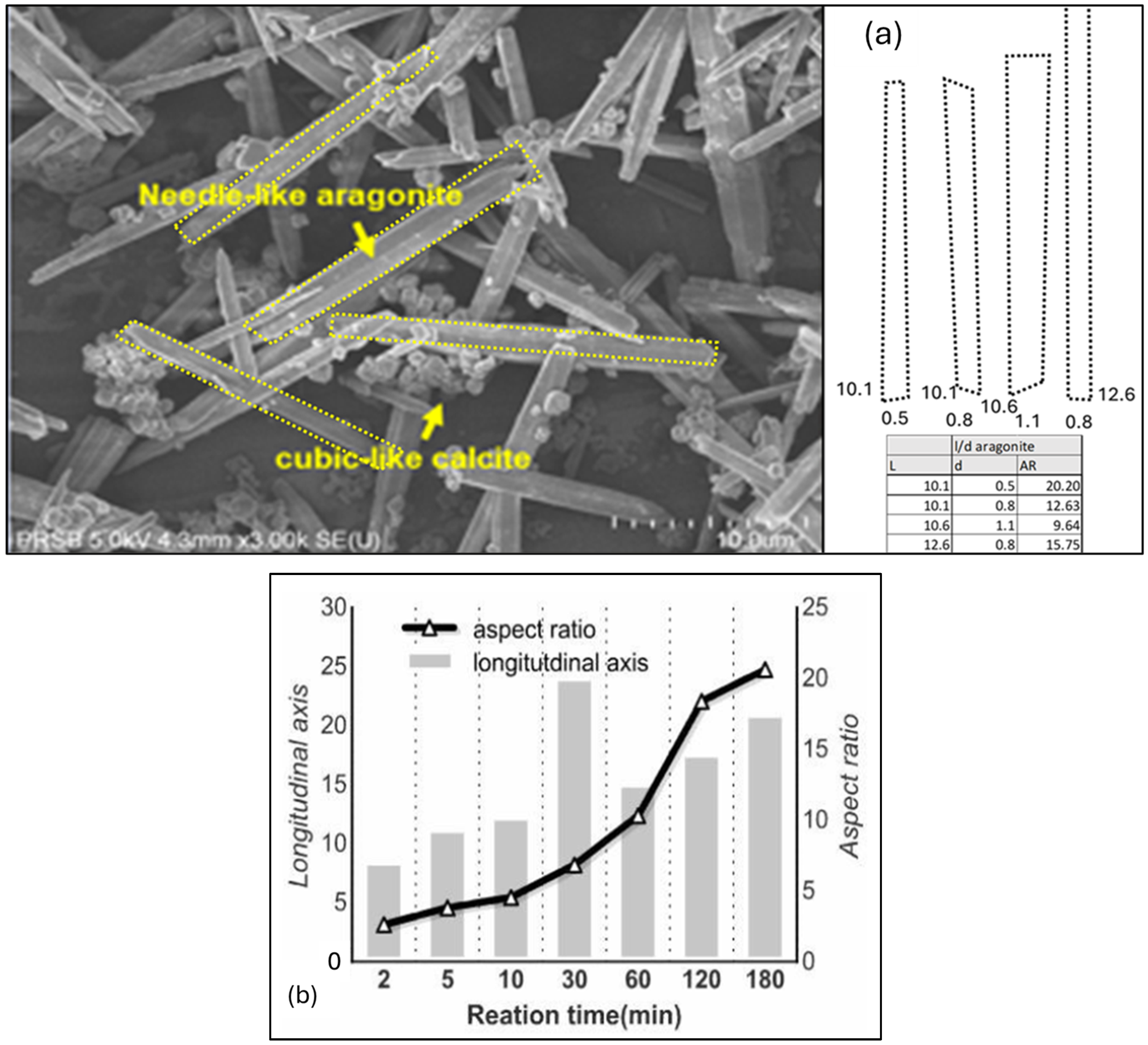
In this study, The Scanning Electron Microscope—SEM—image was obtained from the model Hitachi FESEM SU8020. From the SEM images retrieved, the morphological shape of the aragonite precipitate obtained here is a needle-shape precipitate with a considerably high aspect ratio, A/R, of length over diameter, L/D. The aspect ratio, AR, of aragonite crystalline needle-like structure length over diameter, L/D, was found to be in the range between 9.64 and 20.20 as shown in Figure 13a below.
In comparison, Sang-Jin Ko et al. (2020) [59] previously reported to have successfully investigated the relationship of longitudinal axis size and aspect ratio of aragonite crystal formation using MgCl2, but lower aragonite aspect ratio AR = 5 was achieved after 10 min and further increased to AR = 20 after a longer 180 min of reaction time as shown in Figure 13b below.
Also, Lilit Habte et al. [53] analysis of SEM imaging suggests that the aragonite aspect ratio was highest at AR = 21 when the Mg/Ca ratio was approximately 1.8, and it slowly decreased when Mg/Ca ratio was reduced to 1.0 or, alternately, increased to 3.0 at both ends, as shown in Figure 13b above. The results established in this work using continuous flow mineral carbonation reactor are in line with the studies conducted by both [53,59] in terms of the needle-like shape and the aspect ratio, AR, on the aragonite crystals synthesized, with the exception of reaction time where [59] reported much longer reaction time of up to 180 min to achieve AR = 20.
The shape and high aspect ratio of aragonite crystalline precipitate in this study have good potential for filler application in papermaking [60]. This shape has high potential to be used in strengthening structure due to its high bending and impact strength as reported by Gill and Scott [61], where it was found that precipitated calcium carbonate PCC with aragonite or scalenohedral form is superior to the rhombohedral and ground calcium carbonates in terms of optical properties at high loadings. In addition, W. Shang et al. [62] highlighted that longer aspect ratio means stronger influence of twining whisker structure, providing more marked improvement of paper strength. Therefore, it is of interest to test these long needle-like fillers’ performance differently from conventional fillers in papermaking.

4.5. Thermal Gravimetric Analysis TGA

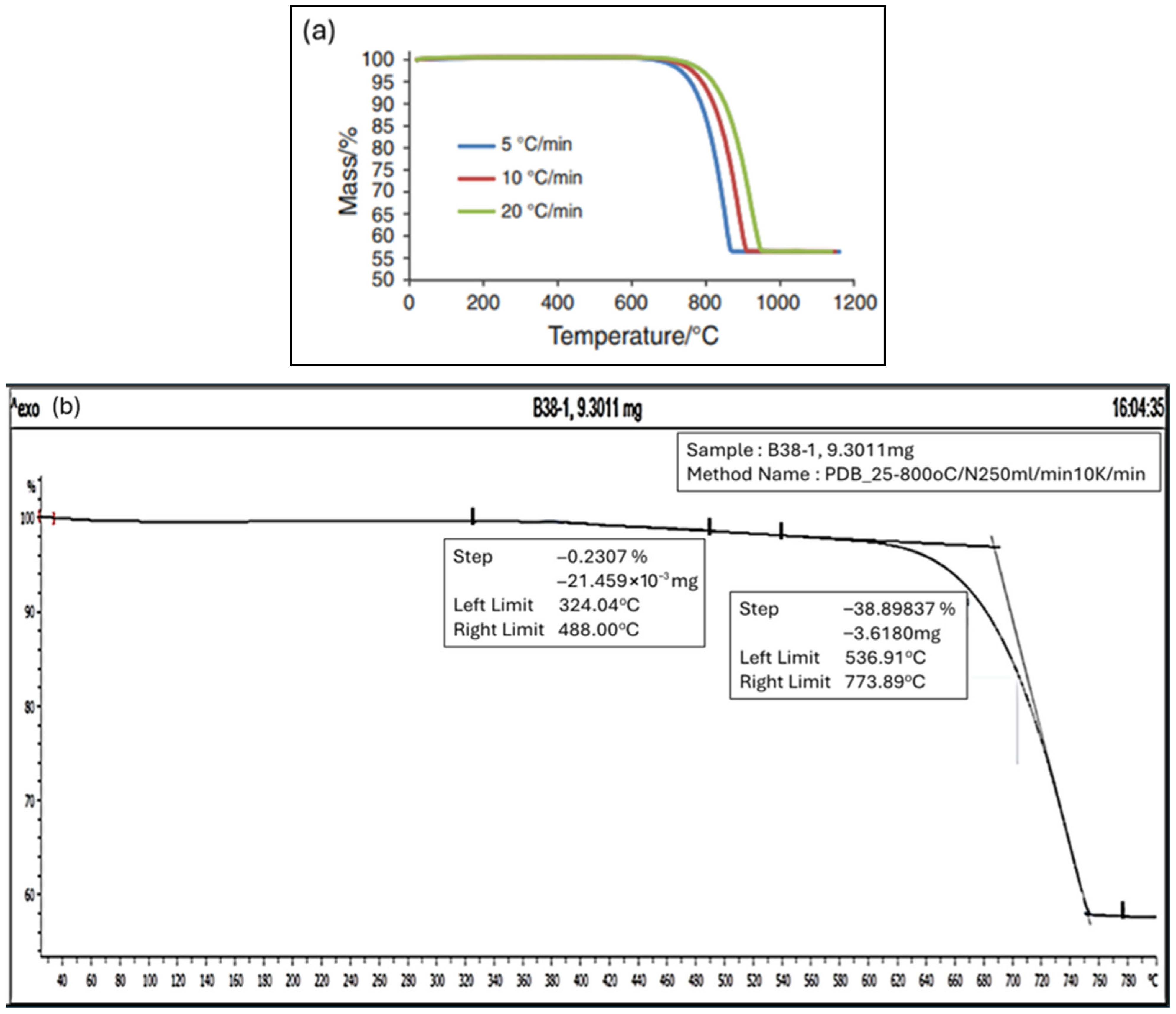
The thermal decomposition analysis of calcium carbonate has been extensively investigated in the past few decades considering the decomposition mechanism and reaction kinetics whereby a number of investigations revealed that the decomposition of calcium carbonate takes place at a definite boundary between the calcium oxide and calcium carbonate crystalline phases [63]. As outlined by Zhuang D et al. [64], a general thermal decomposition curve of calcium carbonate consists of three distinct stages with the first stage mass loss occurring from 50 °C deriving from the release of free and bound water; the second stage of mass loss, which is the main highlight, occurs from the actual decomposition of calcium carbonate releasing carbon dioxide gas; and, finally, at the third stage, where the mass loss of the sample is no longer related to calcium carbonate decomposition. Galan et al. [65] reported that various heat rates provided during the TGA provide slightly different decomposition curves, especially at the third stage, where ultimate decomposition temperature was between 850 °C and 950 °C due to pyrolysis effect. Another, more recent, work by Zhuang et al. [64] indicate that the peak values of the temperature for pure calcium carbonate decomposition were at 560 °C, 587 °C, 723 °C, and 811 °C, respectively, at different heating rate settings of 10, 20, 30, and 40 °C/min, and with a final mass loss of 58%, 55%, 45%, and 42%, respectively. Figure 14a provided below shows the reference TGA curve by [31].
In relation to this research, the dry powder samples from all the 13 runs were mixed and shaken until a uniform mixture was achieved. Approximately 9.3 mg of the dry powder sample was placed on the TGA thimble with heating increases at 10 °C/min, and N2 flow of 50 mL/min until temperature reached 800 °C cutoff. The thermal gravimetric analysis, TGA, is carried out to analyze the material decomposition trending of the solid precipitate when the temperature is slowly heated from 40 °C to a high of 800 °C. The decomposition trending results are shown in Figure 14b below.
The thermal decomposition trend of the solid precipitate in this work indicates the following observations:
(a)
Minor decomposition starts taking place between 400 °C and 550 °C, possibly from the decomposition of traces of magnesium oxides or brucite, which originate from the traces of magnesium metal ion complex as detected during the ICP analysis earlier. TGA decomposition analysis conducted by Wong et al. [66] reported that TGA weight loss of magnesium oxide MgO was approximately at 70% at 550 °C also supportsd this observation.
(b)
Major decomposition occurs from 550 °C to 750 °C, strongly suggesting similar decomposition temperature of calcium carbonate CaCO3 pure sample as reported by Isabel Galan et al. (2012) [65] and further studied by Zhuang et al. (2025) [64] under different thermal decomposition conditions.
(c)
The decomposition, or weight loss, stopped after 800 °C, leaving 56% of the original weight. This finding is similar to the studies conducted by [64], where the corresponding weight loss for 10 °C/min and 15 °C/min was between 58% and 55% of the initial weight.
The result is in good agreement with mass balance after CaCO3 decomposition, where 44% represents the weight of CO2 which released into the atmosphere, leaving 56% of the content of CaO solids with reference to the decomposition equation below:
CaCO3(s) → CaO (s) + CO2 (g)
Therefore aragonite crystalline carbonates can be labeled as a green product which consumes 0.44 kg CO2 per 1 kg of precipitated calcium carbonates PCC.

4.6. Discussion

The solid precipitate produced via the continuous mineral carbonation process was successfully characterized in terms of its physico-chemical characteristics, which included metal contents analysis, physical crystalline phase determination, particle size analysis, physical morphology determination, and thermal decomposition characteristics. Based on thermal gravimetric analysis, TGA, results, the decomposition of the precipitate takes place between 550 °C and 750 °C, strongly indicating the sample is of calcium carbonate CaCO3 origin with slight decomposition happening at lower 550 °C possibly from magnesium oxide contaminants. Induction coupled plasma, ICP, analysis further supported this observation with >94% of the metal ions presence consisting of Ca2+ element and remaining 5% Mg2+. Particle size distribution, PSD, analysis results show the particle size precipitated at an average D50 of 9.61 microns with D10 and D90 spreads between 8.67 micron and 11.35 micron suitable for specialized filler applications. In terms of morphology, XRD analysis further indicates that the calcium carbonate CaCO3 produced from the experiments consists of between 73% and 91% aragonite crystalline phase with calcite phase as the dominant remaining crystalline structure. Imaging results from FESEM suggest that the morphology of the precipitate obtained is dominantly needle-shape aragonite with a good aspect ratio AR between 9.64 and 20.20, highly regarded as having high tensile strength suitable for paper making and bio-application.

5. Conclusions

A continuous production method of aragonite material was proposed and tested using MgCl2 as a chemical inducer. An elaborate design experiment to establish the main factors and optimizing the production 3D contour was successfully executed. The usage of chemical inducer MgCl2 treat rate was also optimized but still functionally effective to yield needle-shaped aragonite crystalline precipitate with high aspect ratio AR. Characterization results revealed that the aragonite precipitate has a physical morphology of needle-like shape with quite a good aspect ratio (length/diameter), AR, of between 9.64 and 20.20. Particle size distribution, PSD, analysis results show the particle size precipitated at an average D50 of 9.61 microns with D10 and D90 spreads between 8.67 micron and 11.35 micron suitable for specialized filler applications. Thermal gravimetric analysis also revealed a similar calcium carbonate decomposition feature with solid mass remaining after TGA test at approximately 56%. The overall characterization results provide first-cut physical and chemical properties analysis suggesting suitability for several filler applications requiring high tensile stress requirements such as paper making, bio filler application, and artificial bone replacement material.

Author Contributions

Conceptualization, M.G.M.N.; methodology, M.G.M.N.; software, M.G.M.N.; validation, M.G.M.N.; formal analysis, M.G.M.N.; investigation M.G.M.N., M.S.O. and R.S.; resources, M.G.M.N., M.S.O. and R.S.; data curation, M.G.M.N.; writing—original draft preparation, M.G.M.N.; writing—review and editing, M.G.M.N., N.Y.Y. and M.H.H.J.; visualization, M.G.M.N.; supervision, N.Y.Y. and M.H.H.J.; project administration, N.Y.Y.; funding acquisition, N.Y.Y. All authors have read and agreed to the published version of the manuscript.

Funding

This research was funded by PRSB-UKM R&D Collaboration Project with grant number “KK - 2021- 017” under the title “The Development of Continuous CO2 Mineral Carbonation Process”.

Data Availability Statement

Restrictions apply to the datasets. The datasets presented in this article are not readily available because the data are part of an ongoing study and is undergoing market seeding process. Requests to access the datasets should be directed to mghadaffi_mnor@petronas.com.

Acknowledgments

During the preparation of this manuscript, I would like to record my sincere acknowledgement for Nasir Darman, PETRONAS for endorsing this research grant with UKM. Also, to Hatarmizi Hassan for meticulously following the progress of this project from the start to end. Last but not least, to my fellow scientists, especially M Syazwan Onn and Ruzilah Sanum whom exhaustively provided their utmost support, energy, and with day in and day out until the day when we finally achieved the much-sought victory!

Conflicts of Interest

Authors Mohammad Ghaddaffi M. Noh, Onn M. S. and Sanum R. were employed by the company PETRONAS Research Sdn. Bhd. The remaining authors declare that the research was conducted in the absence of any commercial or financial relationships that could be construed as a potential conflict of interest.

References

  1. Shokrollahi, M.; Teymouri, N.; Navarri, P. Identification and evaluation of most promising CO2 utilization technologies: Multi criteria decision analysis and techno-economic assessment. J. Clean. Prod. 2024, 434, 139620. [Google Scholar] [CrossRef]
  2. Aresta, M.; Quaranta, E.; Tommasi, I.; Giannoccaro, P.; Ciccarese, G. Carbon dioxide utilization in the chemical industry. Chim. Ital. 1995, 125, 509–538. [Google Scholar]
  3. Sakakura, T.; Choi, J.-C.; Yasuda, H. Transformation of Carbon Dioxide. Chem. Rev. 2007, 107, 2365–2387. [Google Scholar] [CrossRef] [PubMed]
  4. Aresta, M.; Dibenedetto, A.; Angelini, A. The changing paradigm in CO2 utilization. J. CO2 Util. 2013, 3–4, 65–73. [Google Scholar] [CrossRef]
  5. Metz, B.; Davidson, O.; de Coninck, H.; Loos, M.; Meyer, L. IPCC Special Report on Carbon Dioxide Capture and Storage Intergovernmental Panel on Climate Change; IPCC: Geneva, Switzerland, 2005. [Google Scholar]
  6. Huijgen, W.J.J. Carbon Dioxide Sequestration by Mineral Carbonation. Ph.D. Thesis, Energy Research Centre of the Netherlands, Petten, The Netherlands, 2007. [Google Scholar]
  7. Carbon Upcycling Technologies 2023. Available online: https://carbonupcycling.com/ (accessed on 28 January 2023).
  8. Sinha, A. A Mechanochemical Process to Produce Exfoliated Nanoparticles. U.S. Patent Application No. WO/2019/012474, 12 July 2018. [Google Scholar]
  9. Sinha, A. A Mechanically Carboxylated Fly Ash, Methods of Its Production and Uses Thereof. U.S. Patent Application No. WO/2021/087605, 2 October 2020. [Google Scholar]
  10. Sinha, A. Compositions Comprising a Mechanochemically Carboxylated Mineral Filler and a Cement and/or Asphalt Binder. U.S. Patent Application No. WO/2021/087606, 2021. [Google Scholar]
  11. Choudens-Sánchez, D.; González, L.A. Calcite and aragonite precipitation under controlled instantaneous supersaturation: Elucidating the role of CaCO3 saturation state and Mg/Ca ratio on calcium carbonate polymorphism. J. Sediment. Res. 2009, 79, 363–376. [Google Scholar]
  12. Park, W.K.; Ko, S.-J.; Lee, S.W.; Cho, K.-H.; Ahn, J.-W.; Han, C. Effects of magnesium chloride and organic additives on the synthesis of aragonite precipitated calcium carbonate. J. Cryst. Growth 2008, 310, 2593–2601. [Google Scholar] [CrossRef]
  13. Jung, W.M.; Kang, S.H.; Kim, W.-S.; Choi, C.K. Particle morphology of calcium carbonate precipitated by gas–liquid reaction in a Couette–Taylor reactor. Chem. Eng. Sci. 2000, 55, 733–747. [Google Scholar] [CrossRef]
  14. Liendo, F.; Arduino, M.; Deorsola, A.F.; Bensaid, S. Factors controlling and influencing polymorphism, morphology and size of calcium carbonate synthesized through the carbonation route: A review. Powder Technol. 2022, 398, 117050. [Google Scholar] [CrossRef]
  15. Meldrum, F.C.; Hyde, S.T. Morphological influence of magnesium and organic additives on the precipitation of calcite. J. Cryst. Growth 2001, 231, 544–558. [Google Scholar] [CrossRef]
  16. Hashim, M.S.; Kaczmarek, S.E. The transformation of aragonite to calcite in the presence of magnesium: Implications for marine diagenesis. Earth Planet. Sci. Lett. 2021, 574, 117166. [Google Scholar] [CrossRef]
  17. Nancollas, G.H.; Sawada, K. Formation of Scales of Calcium Carbonate Polymorphs: The Influence of Magnesium Ion and Inhibitors. J. Pet. Technol. 2012, 34, 645–652. [Google Scholar] [CrossRef]
  18. Bischoff, J.L. Kinetics of calcite nucleation: Magnesium ion inhibition and ionic strength catalysis. J. Geophys. Res. 1968, 73, 3315–3322. [Google Scholar] [CrossRef]
  19. Bischoff, J.L.; Fyfe, W.S. Catalysis, inhibition, and the calcite-aragonite transformation. Am. J. Sci. 1968, 266, 65–79. [Google Scholar] [CrossRef]
  20. Berner, R.A. The Role of Magnesium in the Crystal Growth of Calcite and Aragonite from Sea Water. Geochim. Et. Cosmochim. Acta 1975, 39, 489–494. [Google Scholar] [CrossRef]
  21. Astilleros, J.M.; Fernández-Díaz, L.; Putnis, A. The role of magnesium in the growth of calcite: An AFM study. Chem. Geol. 2010, 271, 52–58. [Google Scholar] [CrossRef]
  22. Nielsen, L.C.; De Yoreo, J.J.; DePaolo, D.J. General model for calcite growth kinetics in the presence of impurity ions. Geochim. Cosmochim. Acta 2013, 115, 100–114. [Google Scholar] [CrossRef]
  23. Mucci, A.; Morse, J.W. The incorporation of Mg2+ and Sr2+ into calcite overgrowths: Influences of growth rate and solution composition. Geochim. Cosmochim. Acta 1983, 47, 217–233. [Google Scholar] [CrossRef]
  24. Chen, P.-C.; Clifford, T.Y.; Lee, K.C. Morphology and growth rate of calcium carbonate crystals in a gas-liquid-solid reactive crystallizer. Chem. Eng. Sci. 1997, 52, 4171–4177. [Google Scholar] [CrossRef]
  25. Christoffersen, J.; Christoffersen, M.R. Kinetics of spiral growth of calcite crystals and determination of the absolute rate constant. J. Cryst. Growth 1990, 100, 203–211. [Google Scholar] [CrossRef]
  26. Hu, Z.; Deng, Y. Synthesis of needle-like aragonite from calcium chloride and sparingly soluble magnesium carbonate. Powder Technol. 2004, 140, 10–16. [Google Scholar] [CrossRef]
  27. Wang, L.; Sondi, I.; Matijević, E. Preparation of Uniform Needle-Like Aragonite Particles by Homogeneous Precipitation. J. Colloid Interface Sci. 1999, 218, 545–553. [Google Scholar] [CrossRef]
  28. Sun, W.; Jayaraman, S.; Chen, W.; Persson, K.A.; Ceder, G. Nucleation of metastable aragonite CaCO3 in seawater. Proc. Natl. Acad. Sci. USA 2015, 112, 3199–3204. [Google Scholar] [CrossRef] [PubMed]
  29. Kajiyama, S.; Nishimura, T.; Sakamoto, T.; Kato, T. Aragonite Nanorods in Calcium Carbonate/Polymer Hybrids Formed through Self-Organization Processes from Amorphous Calcium Carbonate Solution. Small 2014, 10, 1634–1641. [Google Scholar] [CrossRef] [PubMed]
  30. Ramakrishna, C.; Thenepalli, T.; Huh, J.-H.; Ahn, J.W. Preparation of Needle like Aragonite Precipitated Calcium Carbonate (PCC) from Dolomite by Carbonation Method. J. Korean Ceram. Soc. 2016, 53, 7–12. [Google Scholar] [CrossRef]
  31. Meigen, W. A simple reaction for distinguishing between aragonite and calcite. Fresenius. Z. Für Anal. Chem. 1902, 41, 119–120. [Google Scholar] [CrossRef]
  32. Linck, G. Die Bildung der Oolithe und Rogensteine. Nues Jahebuch Beil 1903, 16, 495–513. [Google Scholar]
  33. Johnston, J.; Merwin, H.E.; Williamson, E.D. The several forms of calcium carbonate. Am. J. Sci. 1916, 41, 473–512. [Google Scholar] [CrossRef]
  34. Kohlschütter, V.; Egg, C. Über somatoide Bildungsformen. Helv. Chim. Acta 1925, 8, 457–469. [Google Scholar] [CrossRef]
  35. Saylor, C.H. Calcite and aragonite. J. Phys. Chem. 1927, 32, 1441–1460. [Google Scholar] [CrossRef]
  36. Faivre, M.R. Reserche des conditions physiochimiques de précipitation des trois formes cristallines du carbonate de calcium prépare par double décompositon due chlorure de calcium et du carbonate de sodium. Comptes Rendus 1946, 222, 140. [Google Scholar]
  37. Togari, K.; Togari, S. Conditions controlling the crystal form of calcium carbonate minerals (I) (on influence of the temperature and the presence of magnesium ion). J. Fac. Sci. Hokkaido Univ. Ser. 4 Geol. Miner. 1955, 9, 55–65. [Google Scholar]
  38. Zeller, E.; Wray, J. Factors influencing precipitation of calcium carbonate. Bull. Am. Assoc. Pet. Geol. 1956, 40, 140–152. [Google Scholar]
  39. Jones, B. Review of calcium carbonate polymorph precipitation in spring systems. Sediment. Geol. 2017, 353, 64–75. [Google Scholar] [CrossRef]
  40. Suganuma, I. On the Constituents and Genesis of a Few Minerals Produced from Hot Springs and Their Vicinities in Japan. III. Calcium Carbonate Minerals Deposited from Effervescent Springs. Bull. Chem. Soc. Jpn. 1928, 3, 87–89. [Google Scholar] [CrossRef]
  41. Goto, M. Some mineralo-chemical problems concerning calcite and aragonite, with special reference to the genesis of aragonite. J. Fac. Sci. Hokkaido Univ. Ser. 4 Geol. Miner. 1961, 10, 571–640. [Google Scholar]
  42. Roques, H.; Girou, A. Kinetics of the formation conditions of carbonate tartars. Water Res. 1974, 8, 907–920. [Google Scholar] [CrossRef]
  43. Chakrabarty, D.; Mahapatra, S. Aragonite crystals with unconventional morphologies. J. Mater. Chem. 1999, 9, 2953–2957. [Google Scholar] [CrossRef]
  44. Nebel, H.M. Epple Continuous preparation of calcite, aragonite and vaterite, and of magnesium-substituted amorphous calcium carbonate (Mg-ACC). J. Inorg. Gen. Chem. 2008, 634, 1439–1443. [Google Scholar]
  45. Chen, J.L. Xiang Controllable synthesis of calcium carbonate polymorphs at different temperatures. Powder Technol. 2009, 189, 64–69. [Google Scholar] [CrossRef]
  46. Tai, C.Y.; Chen, F. Polymorphism of CaCO3 precipitated in a constant-composition environment. AICHE J. 1998, 44, 1790–1798. [Google Scholar] [CrossRef]
  47. Hu, Z.; Shao, M.; Cai, Q.; Ding, S.; Zhong, C.; Wei, X.; Deng, Y. Synthesis of needle-like aragonite from limestone in the presence of magnesium chloride. J. Mater. Process. Technol. 2009, 209, 1607–1611. [Google Scholar] [CrossRef]
  48. Matsumoto, M.; Fukunaga, T.; Onoe, K. Polymorph control of calcium carbonate by reactive crystallization using microbubble technique. Chem. Eng. Res. Des. 2010, 88, 1624–1630. [Google Scholar] [CrossRef]
  49. Gomez-Villalba, L.S.; Lo´pez-Arce, P.; Alvarez de Buergo, M.; Fort, R. Atomic defects and their relationship to aragonite-calcite transformation in portlandite nanocrystal carbonation. Cryst. Growth Des. 2012, 12, 4844–4852. [Google Scholar] [CrossRef]
  50. Shen, P.; Lu, J.; Zhang, Y.; Jiang, Y.; Zhang, S.; Poon, C.S. Preparation aragonite whisker-rich materials by wet carbonation of cement: Towards yielding micro-fiber reinforced cement and sequestrating CO2. Cem. Concr. Res. 2022, 159, 106891. [Google Scholar] [CrossRef]
  51. Ding, X.; Li, W.; Chang, J. Preparation of aragonite from calcium carbonate via wet carbonation to improve properties of steel slag building materials. Constr. Build. Mater. 2024, 451, 138763. [Google Scholar] [CrossRef]
  52. Altiner, M.; Yildirim, M. Production and characterization of synthetic aragonite prepared from dolomite by eco-friendly leaching–carbonation process. Adv. Powder Technol. 2017, 28, 553–564. [Google Scholar] [CrossRef]
  53. Habte, L.; Khan, M.D.; Shiferaw, N.; Farooq, A.; Lee, M.-H.; Jung, S.-H.; Ahn, J.W. Synthesis, Characterization and Mechanism Study of Green Aragonite Crystals from Waste Biomaterials as Calcium Supplement. Sustainability 2020, 12, 5062. [Google Scholar] [CrossRef]
  54. Morse, J.W.; Arvidson, R.S.; Lüttge, A. Calcium carbonate formation and dissolution. Chem. Rev. 2007, 107, 342–381. [Google Scholar] [CrossRef]
  55. Onn, M.S.; Noh, M.G.M.; Shukor, M.S.M.; Isa, M.A. Experimental Proof of Concept for Continuous Mineral Carbonation System using High Pressure Calcium Hydroxide Spray into Supercritical CO2. J. Phys. Conf. Ser. 2019, 1349, 01207981. [Google Scholar]
  56. D’aMora, M.; Liendo, F.; Deorsola, F.A.; Bensaid, S.; Giordani, S. Toxicological profile of calcium carbonate nanoparticles for industrial applications. Colloids Surf. B Biointerfaces 2020, 190, 110947. [Google Scholar] [CrossRef]
  57. Memar, M.Y.; Adibkia, K.; Farajnia, S.; Kafil, H.S.; Dizaj, S.M.; Ghotaslou, R. Biocompatibility, cytotoxicity and antimicrobial effects of gentamicin-loaded CaCO3 as a drug delivery to osteomyelitis. J. Drug Deliv. Sci. Technol. 2019, 54, 101307. [Google Scholar] [CrossRef]
  58. Sturcal, F. Available online: https://polymer-additives.specialchem.com/product/a-specialty-minerals-sturcal-f (accessed on 19 August 2025).
  59. Ko, S.-J.; Park, W.-K.; Lee, S.-W.; Han, C.; Ahn, J.-W. Control of Particle Size and Aspect Ratio of Aragonite Precipitated Calcium Carbonate on Adding Seed. J. Korean Earth Sci. Soc. 2007, 44, 153–158. [Google Scholar]
  60. Hu, Z.; Shao, M.; Li, H.; Cai, Q. Synthesis of Needle-Like Aragonite Crystals in the Presence of Magnesium Chloride and Their Application in Papermaking. Adv. Compos. Mater. 2009, 18, 315–326. [Google Scholar] [CrossRef]
  61. Gill, T.; Scott, W. The relative effects of different calcium carbonate filler pigments on optical properties. Tappi J. 1987, 70, 93–99. [Google Scholar]
  62. Shang, W.; Liu, Q.; He, E.; Chen, S. Study on properties of polymers packed by aragonite whisker. Proc. IEEE Intl Conf. Prop. Appl. Dielectr. Mater. 2000, 1, 431–434. [Google Scholar]
  63. Karunadasa, K.S.; Manoratne, C.; Pitawala, H.; Rajapakse, R. Thermal decomposition of calcium carbonate (calcite polymorph) as examined by in-situ high-temperature X-ray powder diffraction. J. Phys. Chem. Solids 2019, 134, 21–28. [Google Scholar] [CrossRef]
  64. Zhuang, D.; Chen, Z.; Sun, B. Thermal Decomposition of Calcium Carbonate at Multiple Heating Rates in Different Atmospheres Using the Techniques of TG, DTG, and DSC. Crystals 2025, 15, 108. [Google Scholar] [CrossRef]
  65. Galan, I.; Glasser, F.; Andrade, C. Calcium carbonate decomposition. CEEC-TAC1 Conference Special Issue. J. Therm. Anal. Calorim. 2013, 111, 1197–1202. [Google Scholar] [CrossRef]
  66. Wong, C.W.; Chan, Y.S.; Jeevanandam, J.; Pal, K.; Bechelany, M.; Elkodous, M.A.; El-Sayyad, G.S. Response Surface Methodology Optimization of Mono-dispersed MgO Nanoparticles Fabricated by Ultrasonic-Assisted Sol–Gel Method for Outstanding Antimicrobial and Antibiofilm Activities. J. Clust. Sci. 2020, 31, 367–389. [Google Scholar] [CrossRef]
Figure 1. A detailed crystal growth mechanism of green aragonite as proposed by Habte [54].
Processes 13 03142 g001
Figure 2. Laboratory setup for aragonite synthesis from lime solution and magnesium chloride as chemical inducer.
Processes 13 03142 g002
Figure 3. Selected XRD diffractogram results for selected samples from the two-level full factorial design of the 24 run experiment.
Processes 13 03142 g003
Figure 4. 3D factor interaction cube to better picture the responses: individual single factor responses, two-way interaction factor responses, and three-way factor interaction responses.
Processes 13 03142 g004
Figure 5. Half normal plot; sum of squares and p-value for the individual factor responses A, B, and C; two-way interaction factor responses AB, AC, and BC; and three-way factor interaction responses ABC.
Processes 13 03142 g005
Figure 6. 3D Contour plot for the effect of reaction temperature (40 °C, 65 °C, and 90 °C) and reaction time (1 min, 3 min, 5 min, and 10 min) at Mg/Ca ratio of 0.4 for the percentage yield of aragonite precipitate.
Processes 13 03142 g006
Figure 7. Plot of Occurrence of Non-aragonite phase (100%–Aragonite Purity) versus Ratio of Mg-to-Ca in reactant between 0.2 and 1.28 at Fixed Reaction Time of 10 min and Temperature of 90 °C.
Processes 13 03142 g007
Figure 8. Trend of MgCl2 losses for reaction time between 1 min and 10 min at operating conditions of 90 °C and Mg/Ca ratio of 0.4.
Processes 13 03142 g008
Figure 9. (a) Laboratory setup; and (b) Schematics of the continuous mineral carbonation reactor.
Processes 13 03142 g009
Figure 10. Selected crystalline phase diffractogram and analysis obtained from Diffrac Plus EVA for the 13 back-to-back samples run using the continuous reactor system.
Processes 13 03142 g010
Figure 11. Relative composition of crystalline phase aragonite, calcite, and magnesium–calcite complex in solid precipitate products for 13 back-to-back continuous runs obtained from XRD analysis.
Processes 13 03142 g011
Figure 12. Example of the PSD analysis conducted on the precipitate sample for Run #1.
Processes 13 03142 g012
Figure 13. (a) Images of needle-shaped crystalline precipitate with aspect ratio AR (L/D) between 9.64 and 20.20 synthesized in this study using the continuous mineral carbonation reactor. (b) SEM images of aragonite AR were highest at AR = 21 when the Mg/Ca ratio was approximately 1.8 by [55].
Processes 13 03142 g013
Figure 14. (a) Reference TGA analysis by Isabel Galan [65] about different heating rates’ effect on thermal decomposition curve of pure calcium carbonate. (b) TGA analysis by thermal gravimetric analysis for solid precipitate for the 13 continuous run samples.
Processes 13 03142 g014
Table 1. Randomized run for the response aragonite yield for the respective factor magnesium-to-calcium reactant ratio Mg/Ca assigned as Factor A, reaction temperature assigned as factor B, and reaction time assigned as factor C.
Randomized RunRandomized RunFactor A:
Mg-to-Ca Ratio
(A)
Factor B:
Temperature
(B)
Factor C:
Reaction Time
(C)
Response Y
Aragonite Yield
- °C Minutes %
1310.240101.7
120.24018.8
930.2901<1.0
2440.4901096.3
2250.4901089.0
260.2401<1.0
1970.2901032.9
1580.24010<1.0
690.4401<1.0
21100.2901020.3
8110.2901<1.0
18120.44010<1.0
4130.44015.4
12140.49012.4
7150.2901<1.0
3160.24015.7
14170.24010<1.0
11180.49018.3
23190.4901079.4
10200.49012.7
5210.4401<1.0
20220.2901019.2
16230.44010<1.0
17240.44010<1.0
Table 2. Total composition of metal ions Mg2+ and Ca2+ in freshly prepared reactant (left) and relative composition of metal ions Mg2+ and Ca2+ in solid precipitate or products (right) analysis via Induction Coupled Plasma, ICP, method for 13 performance run using continuous reactor system.
RunsMetal Ions (ppm) in ReactantMetal Ions (%) in Solids
MgCaTotalMgCa
123011,20011,4302.0197.99
247510,81111,2864.2195.79
354810,96011,5084.7695.24
4440998810,4284.2295.78
555011,00811,5584.7695.24
658010,70511,2855.1494.86
752910,58811,1174.7695.24
853910,79011,3294.7695.25
939011,20111,5913.3696.64
1059011,00511,5955.0994.91
1154910,99811,5474.7595.25
12290989910,1892.8597.15
1353910,78911,3284.7695.24
Average48110,765 4.2695.74
Standard Deviation113406 0.950.95
Table 3. Particle Size Distribution PSD analysis of the crystalline precipitate.
RunsParticle Size Distribution PSD Analysis (Micron)
10%50%90%
13.499.4718.37
23.2211.3523.89
34.1110.7821.78
44.349.0115.21
55.119.1218.32
63.679.4518.98
74.219.0117.34
85.0110.1219.23
94.129.4518.33
105.559.3418.46
116.128.6716.78
123.029.3518.67
136.239.7519.01
Disclaimer/Publisher’s Note: The statements, opinions and data contained in all publications are solely those of the individual author(s) and contributor(s) and not of MDPI and/or the editor(s). MDPI and/or the editor(s) disclaim responsibility for any injury to people or property resulting from any ideas, methods, instructions or products referred to in the content.