Abstract
The practical application of transparent supercapacitors (TSCs) is limited by the inherent trade-off between transparency and conductivity, as well as the environmental and economic drawbacks of electrode materials. This study presents a novel and scalable method for fabricating porous carbon-modified silk-derived carbon fiber meshes as electrode materials for transparent supercapacitors. The process involves the in situ growth of a cobalt organic complex on a silk mesh, followed by carbonization to produce a flexible, transparent carbon fiber mesh with a hierarchical porous structure (specific surface area: 570 m2/g). The resulting material exhibits good mechanical properties and electrical conductivity due to the nanographene-like structure formed during the cobalt-catalyzed carbonization process. This TSC achieves an optical transparency of up to 65% and an aerial capacitance of 9.65 mF/cm2 at a scan rate of 0.01 V/s, surpassing many existing transparent electrodes. Additionally, the device demonstrates outstanding electrochemical stability, retaining 89% of its initial capacitance after 2000 cycles at a scan rate of 0.5 V/s, showcasing superior durability. This study presents a pioneering method for developing TSCs by utilizing sustainable silk-derived carbon materials and a cost-effective fabrication process.
1. Introduction
Transparent supercapacitors (TSCs) combine high capacitance and optical transparency, making them highly promising for applications in portable electronic devices, smart windows, and displays [1,2,3,4]. Typically, the core components of TSCs include transparent electrolytes, transparent current collectors (such as indium tin oxide, ITO), and transparent electrode materials. Among these, electrode materials play a critical role in determining the performance and transparency of the device. However, the development of transparent electrodes has been hindered by two main challenges: (i) the capacitance of materials is inversely related to their transparency, meaning that achieving high transparency often compromises capacitance performance, and (ii) current material systems face significant limitations in terms of environmental sustainability, cost of preparation, and large-scale manufacturability. For instance, the widely used ITO is dependent on limited indium resources and difficult to recycle, making it unsuitable for larger-scale applications. In recent years, nanomaterials such as MXene, graphene, carbon nanotubes (CNTs), and metal nanowires have shown excellent performance in terms of conductivity and mechanical flexibility [5,6,7,8,9,10,11]. However, their synthesis often relies on hazardous etchants (such as hydrofluoric acid) or complex vapor deposition techniques, leading to high costs and significant environmental concerns. Therefore, the development of scalable fabrication strategies that simultaneously optimize transparency, electrochemical performance, environmental sustainability, and cost-effectiveness remains a critical challenge in advancing transparent energy storage technologies.
In this context, biomass-derived carbon materials have attracted considerable research interest due to their sustainability, tunable structural properties, and inherent conductivity [12,13,14]. Silk, a natural protein fiber composed of fibroin and sericin, features a distinctive β-sheet structure that can transform into graphite-like carbon layers during high-temperature carbonization. Compared to petroleum-based carbon fibers, silk-based carbon fibers originate from abundant, renewable raw materials, and their carbonization process does not require complex catalysts, presenting significant environmental advantages. However, directly carbonized silk fibers typically exhibit a low specific surface area and limited surface chemical activity, which constrains their ability to achieve the energy density required for high-performance energy storage devices [13]. Therefore, optimizing the electrochemical activity of silk-derived carbon materials through structural engineering and surface modification strategies, while preserving their high transparency and mechanical flexibility, has emerged as a critical research focus in this field.
In recent years, metal–organic complexes have shown distinct advantages as precursors for functional carbon materials [15,16,17,18]. By selecting specific metal centers (e.g., Co and Fe) and nitrogen-/sulfur-containing organic ligands (such as imidazole and thiourea), the pore structure, heteroatom doping types, and surface functional group distribution of the carbonized products can be finely tuned at the molecular level. For instance, cobalt-based complexes can generate metal nanoparticles in situ during high-temperature pyrolysis, and their “catalytic graphitization” effect can promote the formation of highly conductive graphene-like domains within the carbon matrix. Simultaneously, the templating effect of these nanoparticles induces a hierarchical porous structure, thereby enhancing the material’s specific surface area and ion transport properties. Moreover, nitrogen species released during complex decomposition can be incorporated into the carbon framework as pyridinic and pyrrolic nitrogen, introducing electrochemically active sites. This integrated “structure–function” design presents a novel strategy for developing high-performance transparent electrodes.
Based on the above analysis, this study presents an innovative strategy that leverages natural silk fibroin as a flexible substrate for the in situ growth of cobalt-imidazole complexes, followed by a controlled carbonization process to fabricate porous carbon-modified transparent silk carbon fiber meshes (TFCs). This design capitalizes on the intrinsic mesh structure of silk fibers (inter-fiber spacing ~300 μm) to achieve high optical transparency (>65%), while cobalt-catalyzed carbonization induces the formation of a nanographene/mesoporous carbon composite layer on the fiber surface and increases the specific surface area (570 m2/g). Electrochemical evaluations demonstrate that the TFC-based transparent all-solid-state supercapacitor achieves an aerial capacitance of 9.65 mF/cm2 at a scan rate of 0.01 V/s, with a capacitance retention of 89% after 2000 cycles at 0.5 V/s. Notably, the entire fabrication process is free from precious metal catalysts or complex instrumentation, offering a scalable and cost-effective approach for the mass production of transparent energy storage devices. This study provides theoretical and technical insights into overcoming the long-standing trade-offs among transparency, electrical conductivity, and capacitance in transparent electrodes.
2. Experimental Section
2.1. Fabrication of Electrode Materials
First, the silk net was pre-soaked for 3–5 min in a 1 mol/L Co(NO3)2 (Aladdin, Shanghai, China) solution and then soaked for 1 min in a 2 mol/Limidazole solution. After each soaking, the remaining liquid was absorbed with qualitative filter paper. In this process, the silk net turned from off-white to purple. To ensure the Co/imidazole complex was uniformly deposited on the silk net surface, the above procedure was repeated 3 times. After that, deionized water was used to soak the silk net for 10 min to remove any excess solution, then the complex-loaded silk net was dried in a vacuum dryer at 60 °C for 12 h. Finally, the prepared samples were calcined at 900 °C for 2 h at a heating rate of 2 °C/min under a N2 atmosphere. After calcination, the samples were washed using 1 M hydrochloric acid (HCl) (Sinopharm Chemical Reagent Co., Ltd., Shanghai, China) for 2 h to remove residual metallic cobalt. This was followed by thorough rinsing with deionized water until the pH of the filtrate became neutral and then drying under vacuum at 60 °C for 12 h.
2.2. Preparation of the Hydrogel Precursor Solution
First, a mixed solution was prepared with 40 mL 2 M acrylamide (AAM) (Sinopharm Chemical Reagent Co., Ltd., Shanghai, China) as the monomer, 80 μL 0.1 M N,N′-methylenebis (acrylamide) (Sinopharm Chemical Reagent Co., Ltd., Shanghai, China) as the cross-linking agent, 400 μL 0.1 M α-ketoglutarate (Sinopharm Chemical Reagent Co., Ltd., Shanghai, China) as the ultraviolet initiator, and 1 M LiCl (Aladdin, Shanghai, China) as the electrolyte.
2.3. Supercapacitor Preparation
The obtained TCFs were cut into rectangular strips and adhered to glass substrates using Nafion as a binder. Specifically, 100 μL of Nafion solution (Aladdin, Shanghai, China) was dropped onto the glass surface, after which the TCFs were placed onto the conductive glass and dried in an oven at 60 °C. A laser with a wavelength of 808 nm was used to fabricate the electrode at a power of 4 W. All samples were prepared under room temperature and ambient air. TCFs were patterned into 10 interdigitated electrodes with a length of 1 cm, a width of 1 mm, and a spacing of ≈300 µm between two neighboring microelectrodes. An appropriate amount of hydrogel precursor solution was applied to the surface of the transparent carbon electrode, and it was exposed to 365 nm UV light for 30 min for photocuring. The capacitor was successfully produced when gel formed on the surface of TCFs.
3. Results and Discussion
Figure 1 shows a schematic illustration of the fabrication process for the porous carbon-modified transparent flexible carbon mesh (TFC). The antiparallel β-sheet conformation represents the most stable structure within silk fibroin molecules. The polar functional groups present in this structure, such as hydroxyl (-OH) and carboxyl (-COOH), facilitate the adsorption of metal ions through electrostatic interactions. Additionally, -NH2 groups can coordinate with metal ions, forming stable chelates [12]. During the synthesis process, the transparent silk mesh was initially immersed in an aqueous Co(NO3)2 solution, allowing the silk fiber surface to fully adsorb Co2+ ions. Subsequently, the material was transferred into an imidazole solution, where Co2+ reacted with imidazole molecules on the silk fiber surface, leading to the in situ formation of hexa-imidazole cobalt nitrate. Finally, the as-prepared composite underwent high-temperature pyrolysis, yielding the TFC network. As shown in Figure S1, the silk mesh loaded with the coordination complex exhibited a color transition from off-white to purple while retaining its optical transparency, confirming the successful adsorption and complexation of cobalt species.
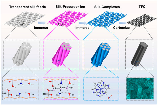
Figure 1.
Schematic illustration of the fabrication of the TFC.
To investigate the physicochemical properties of the coordination complex, samples were initially prepared without deposition onto the silk mesh. Figure 2a shows the SEM image of the independently prepared coordination complex, revealing a nano-/micro-spherical morphology with nanosheet diameters of approximately 3 μm. Figure 2b displays the XRD pattern of the coordination complex. It was observed that the peaks containing the CoN6 coordination site corresponded to the theoretical powder diffraction pattern of hexa-imidazole cobalt nitrate [Co(C3H4N2)3](NO3)2), as derived from the CIF data (CCDC-1142518) [19]. The thermal decomposition characteristics of [Co(C3H4N2)3](NO3)2) are analyzed in Figure 2c,d, which depict the thermogravimetric (TG) and differential scanning calorimetry (DSC) curves. Three distinct thermal decomposition stages are evident. The first endothermic stage, occurring between 50 °C and 100 °C, corresponds to a 3% mass loss due to the removal of adsorbed water. The second exothermic stage begins at 200 °C, with the most significant mass loss (~20%) occurring at 300 °C, likely attributed to the decomposition of nitrate anions and partial oxidation of the imidazole ligand. The third endothermic stage initiates at 490 °C, reaching a maximum mass loss of 60% at 520 °C, corresponding to the complete decomposition of the organic framework and concurrent partial carbonization. Beyond 800 °C, the mass stabilizes, indicating the cessation of further thermal degradation, primarily due to the completion of carbonization reactions. Based on this thermal decomposition analysis, the heat treatment temperature was set at 900 °C, ensuring the complete carbonization of both [Co(C3H4N2)3](NO3)2) and the silk mesh.
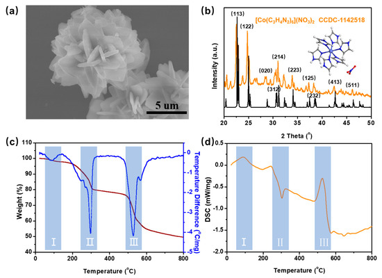
Figure 2.
(a) SEM image of the coordination complex; (b) XRD spectrum of the prepared coordination complex; (c,d) TG and DSC curves of coordination complex.
In this study, the silk mesh successfully retains its original woven structure after carbonization, enabling its use as a substrate material for transparent electronic devices. Figure S2a shows the optical and SEM images of the pristine silk mesh, which consists of perpendicularly woven silk fibers with an average inter-fiber spacing of approximately 300 μm (Figure S2b). The inherent transparency of the silk mesh is attributed to these large inter-fiber gaps, which facilitate the transmission of visible light. After carbonization, the carbon fiber mesh preserves the original woven architecture of the silk fabric, with a ~50% reduction in area (Figure S2c). The inter-fiber spacing contracts to 150 μm, and the fiber diameter decreases to 30–40 μm, while transparency remains effectively maintained. However, carbon fibers derived directly from silk fibers exhibit relatively smooth surfaces and a limited specific surface area, constraining their electrochemical capacitance [20]. Therefore, to enhance the capacitive performance of the material, surface modification strategies are required to introduce structural features that improve ion accessibility and charge storage capability.
Figure 3a shows the optical image of the silk mesh after heat treatment, loaded with [Co(C3H4N2)3](NO3)2). The carbon mesh maintains excellent transparency and flexibility after heat treatment. Figure 3b shows the SEM image of the prepared sample, where the carbon fibers maintain the structure of the silk mesh and the surface has become relatively rough. Figure 3c presents a partial enlargement of the carbon fibers, revealing flake-like structures approximately 1 μm in length and 200 nm in width. Additionally, uniformly dispersed spherical nanoparticles with diameters ranging from 20 to 30 nm are embedded within these flake-like structures. The XRD pattern of the as-prepared sample (Figure S3) exhibits characteristic diffraction peaks at 2θ = 42°, 53°, and 75°, corresponding to the (111), (200), and (220) crystal planes of metallic cobalt. This confirms that during high-temperature calcination, Co2+ ions undergo in situ reduction to form metallic cobalt nanoparticles, in agreement with the structural features observed in the SEM images (Figure 3c). Following the removal of metallic cobalt nanoparticles via hydrochloric acid etching, Figure 3d reveals the porous morphology of the flake-like carbon. The formation of numerous small pores upon cobalt removal highlights the template effect of metal nanoparticles, which contributes to increased surface area and improved ion accessibility.
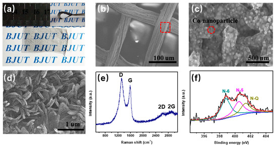
Figure 3.
(a) Optical images of TFC; (b,c) SEM images of TFC; (d) SEM images of TFC after acid treatment; (e) Raman spectrum; and (f) N1s spectra of the carbon derived from [Co(C3H4N2)3](NO3)2).
To minimize the influence of carbon derived from the silk mesh, the prepared TFC underwent ultrasonic treatment during testing, enabling the separation of carbon from the metal–organic complex for further analysis. Figure 3e presents the Raman spectrum of the prepared samples. The characteristic peaks at 1580 cm−1 (G-band) and 1350 cm−1 (D-band) correspond to crystalline sp2 carbon and structural defects, respectively [21,22,23]. At 2750 cm−1, a relatively broad 2D band is observed, suggesting that the carbon fibers have a multi-layer graphene-like structure. These findings confirm that the carbon derived from [Co(C3H4N2)3](NO3)2) exhibits nanographene-like properties, making it suitable as an electrode material for supercapacitors. It is well known that N-doped carbon materials exhibit superior electrical conductivity, increased active sites, and enhanced charge storage properties. Therefore, further analysis of the N1s spectra provides insights into the functional roles of nitrogen species within the material. As depicted in Figure 3f, the N1s spectrum can be fitted with three peaks at 398.8 eV, 400.5 eV, and 401.3 eV, corresponding to pyridinic N (N-6), pyrrolic N (N-5), and graphitic N (NQ), respectively [24,25,26]. These results confirm the successful nitrogen doping of the carbon framework, which is advantageous for improving capacitive performance.
TEM images further confirm that the pores are uniformly distributed across the carbon sheet, with sizes ranging from 20 to 30 nm, consistent with the SEM results (Figure 4a,b). These mesopores contribute to an increased specific surface area, thereby enhancing capacitance. High-resolution TEM (HRTEM) images (Figure 4c,d) reveal that the carbon samples exhibit a high degree of graphitization. In Figure 4c, the red dashed region corresponds to graphitic domains with an interlayer spacing of ~0.37 nm, slightly larger than that of bulk graphite (0.335 nm). In Figure 4d, the pink dashed box highlights the presence of mesopores with diameters ranging from 3 to 6 nm, likely resulting from the removal of metal cobalt. These metallic cobalt nanoparticles were formed through the thermal reduction of Co2+ in [Co(C3H4N2)3](NO3)2). The specific surface area and pore size distribution of the synthesized porous carbon materials were examined through N2 isothermal adsorption–desorption analysis. Figure 4e displays the N2 adsorption–desorption isotherm of the sample, characterized by a type IV profile. A pronounced H2-type hysteresis loop appears in the medium-pressure region, signifying that the derived carbon possesses a hierarchical porous structure composed of both micropores and mesopores [27,28]. Moreover, the sharp rise in adsorption capacity at low pressure indicates the presence of microporous structures. The Brunauer–Emmett–Teller (BET) model was employed to determine the specific surface area, which was found to be 570 m2 g−1, with dominant pore size distributions at 2 nm and 25 nm. Based on these findings, a formation mechanism is proposed (Figure 4f inset). During pyrolysis, the Co2+–imidazole coordination bonds break, leading to the reduction of Co2+ ions into metallic Co atoms by carbon. These Co atoms then aggregate into Co nanoparticles (~5 nm in diameter) to minimize surface energy. The formation of cobalt nanoparticles acts as a catalyst, promoting the graphitization of carbon. As the heat treatment progresses, cobalt nanoparticles further agglomerate into larger particles (~20–30 nm), ultimately leading to the development of graphite-like carbon with a hierarchical porous structure.
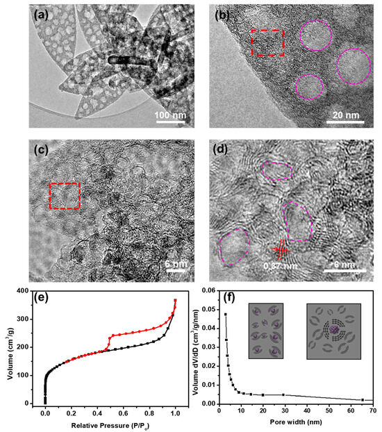
Figure 4.
(a,b) TEM images of the carbon derived from [Co(C3H4N2)3](NO3)2); (c,d) high-resolution transmission electron microscopy (HRTEM) images of the carbon derived from [Co(C3H4N2)3](NO3)2). (e) The N2 adsorption–desorption isotherms and (f) the corresponding pore-size distribution curves of the carbon.
In this study, a laser was employed to pattern the TFC electrode due to its multiple advantages: (1) maximizing electrode transparency, as parallel-plate capacitors require a stack of two TCFs and (2) enabling integrated manufacturing, which simplifies the fabrication process. Figure 5a illustrates the fabrication process of the transparent device. The synthesized transparent carbon mesh was laser-cut into an interdigitated electrode pattern, followed by the polymerization of a gel electrolyte directly onto the electrode surface under UV light exposure. The resulting electrode had an effective area of approximately 2 cm2 (Figure 5b). Figure 5c displays the dimensions of the interdigitated electrodes, with a length of 1 cm, a width of 1.2 mm, and an interelectrode spacing of ~150 μm. The fabricated capacitor exhibited high transparency, allowing clear visibility of text behind the device (Figure 5d). To quantitatively assess the optical transparency of the synthesized materials and fabricated devices, UV-Vis spectroscopy was conducted. As shown in Figure 5e, the pristine silk mesh exhibits a transmittance of 60% in the visible light range (350–800 nm, black line), slightly lower than that of the synthesized transparent carbon mesh electrode material (red line). After fabrication into a transparent capacitor, the transmittance further increases to ~65%, confirming the excellent optical properties of the device (blue line).
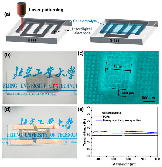
Figure 5.
(a) Schematic diagram of the preparation process of the transparent device; (b) optical photograph and (c) SEM image of interdigitated electrode; (d) optical photograph of transparent device; (e) visible light transmission spectrum of as-prepared samples.
To evaluate the electrochemical performance of the prepared transparent device, we conducted cyclic voltammetry (CV) and constant-current charge–discharge (GCD) tests. Figure 6a displays the CV curves under different scan rates (0.01–0.1 V/s) within the 0–1 V voltage range. At scan rates of 0.01 V/s and 0.02 V/s, the CV curves show an almost rectangular shape with high symmetry, with capacitances of 9.65 mF/cm2 and 7.57 mF/cm2, respectively. This demonstrates that the prepared transparent electrodes possess very good performance. At scan rates of 0.05 V/s and 0.1 V/s, the CV curves exhibit a symmetric fusiform shape, with capacitances of 4.2 mF/cm2 and 7.5 mF/cm2, respectively, also showing good capacitance performance. Figure 6b displays the CV curves of the transparent electrode without porous carbon loading. It can be observed that the curves show a thin narrow strip at different scan rates, indicating poor capacitance performance. Figure 6c displays the CP (chronopotentiometry) curves of the fabricated transparent device. As shown, the electrode material loaded with porous carbon exhibits a low voltage drop, indicating efficient charge–discharge behavior even at a current density of 0.2 mA/cm2. It was observed that the non-symmetry becomes more pronounced at lower current densities, which can be attributed to slower ion transport and a higher contribution from parasitic redox processes, including side reactions related to surface cobalt species. At higher current densities, these effects are suppressed due to the limited time for such reactions to occur, resulting in relatively improved symmetry. In contrast, the electrode without porous carbon shows a higher voltage drop and lower capacitance at a lower current density of 0.1 mA/cm2 (Figure 6d). Figure 6e shows the CV curves and the capacitance retention profile of the TFSC at a scan rate of 0.5 V/s. After 2000 charge–discharge cycles, the TFSC retains 89% of its initial capacitance, demonstrating excellent long-term electrochemical stability. Although the electrode material without porous carbon also exhibits reasonable cycling stability, it delivers a significantly lower capacitance (Figure 6f). As shown in Figure S4, the porous structure of the carbon material remains largely intact, with no significant collapse or degradation observed. The morphology of the carbon fibers and the distribution of pores are well-preserved, demonstrating the mechanical robustness and structural stability of the electrode during prolonged electrochemical operation. This result correlates well with the electrochemical data.
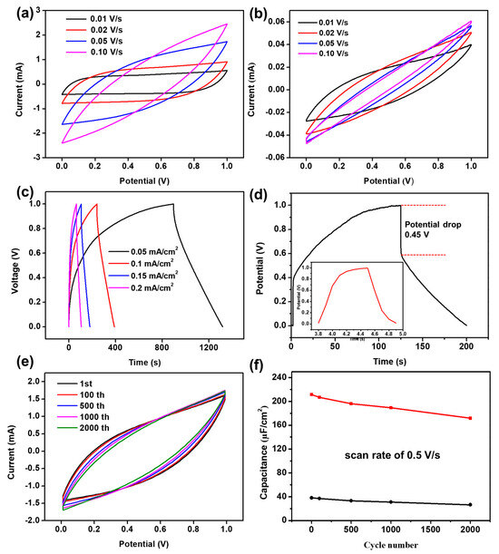
Figure 6.
(a,b) The CV curve of the transparent supercapacitor at sweep speeds of 0.01 V/s, 0.02 V/s, 0.05 V/s, and 0.1 V/s; (c) CP curves of the transparent supercapacitor with current densities of 0.05 mA/cm2, 0.1 mA/cm2, 0.15 mA/cm2, and 0.2 mA/cm2, respectively; (d) CP curves of the transparent supercapacitor at a current density of 0.1 mA/cm2; (e) long-cycle CV curves of transparent supercapacitor; and (f) capacity retention rate.
Using nitrogen-doped graphene as a model, the adsorption characteristics of Li and Cl atoms on the surface of carbon materials were investigated (Figure 7). Nitrogen doping in graphene primarily occurs in three forms: pyridinic N (N-6), pyrrolic N (N-5), and graphitic N (NQ). The adsorption energies of Li atoms on pyridinic N and pyrrolic N were found to be −5.536 eV and −5.442 eV, respectively. In contrast, the adsorption energies of Li atoms in undoped graphene and on graphitic nitrogen are relatively lower. This suggests that nitrogen doping at defect sites significantly enhances the adsorption strength of Li atoms. Conversely, the adsorption energy of Cl atoms on all three types of nitrogen is substantially reduced, indicating that the adsorption strength of Cl atoms is primarily influenced by the nitrogen element. The adsorption energy calculations for Li and Cl atoms show that porphyrin nitrogen is particularly favorable for atomic adsorption. If the content of porphyrin nitrogen can be increased during the material preparation process, it could further enhance the electrochemical performance of the electrode material [29,30].
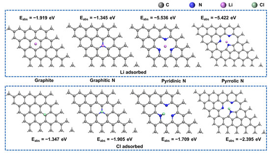
Figure 7.
Adsorption configurations of Li and Cl atoms on various nitrogen-doped graphene surfaces.
4. Conclusions
In conclusion, we designed a facile and cost-effective approach to fabricate a transparent supercapacitor. A Co-imidazole organic complex was in situ-deposited onto the surface of natural silk fibers through a simple stepwise dipping method. Subsequent carbonization at high temperatures and acid treatment resulted in nitrogen-enriched, porous carbon-modified, transparent carbon fiber networks. The resulting transparent supercapacitor showcased 65% light transmittance and a capacitance of 9.65 mF/cm2 at a scan rate of 0.01 V/s. Moreover, it retained 89% of its initial capacitance after 2000 cycles at 0.5 V/s, underscoring its robust electrochemical performance. This work pioneers the use of biomaterials such as proteins or peptides for achieving reliable electronic devices, laying the groundwork for the future development of biomedical applications.
Supplementary Materials
The following supporting information can be downloaded at: https://www.mdpi.com/article/10.3390/pr13103056/s1.
Author Contributions
Conceptualization, D.M. and Y.C.; methodology, D.M.; software, D.M.; validation, D.M., Y.C. and X.N.; formal analysis, X.N.; investigation, R.Z.; resources, E.H.; data curation, X.N.; writing—original draft preparation, D.M.; writing—review and editing, D.M.; visualization, D.M.; supervision, R.Z.; project administration, D.M.; funding acquisition, R.Z. All authors have read and agreed to the published version of the manuscript.
Funding
This research was funded by the Shandong Provincial Natural Science Foundation, grant numbers [ZR202102270491 and ZR2019BF027]. And the APC was funded by [ZR202102270491].
Data Availability Statement
The original contributions presented in this study are included in the article. Further inquiries can be directed to the corresponding author.
Conflicts of Interest
The authors declare that they have no known competing financial interests or personal relationships that could have appeared to influence the work reported in this paper.
References
- Atta, M.M.; Fahrim, R.A. Flexible and wearable supercapacitors: A short review. J. Energy Storage 2021, 44, 103475. [Google Scholar] [CrossRef]
- Wang, Y.; Wu, X.; Han, Y.; Li, T. Flexible supercapacitor: Overview and outlooks. J. Energy Storage 2021, 42, 103053. [Google Scholar] [CrossRef]
- Sun, Z.; Qu, K.; You, Y.; Huang, Z.; Liu, S.; Li, J.; Hu, Q.; Guo, Z. Overview of cellulose-based flexible materials for supercapacitors. J. Mater. Chem. A 2021, 9, 7278–7300. [Google Scholar] [CrossRef]
- Liu, T.; Yan, R.; Huang, H.; Pan, L.; Cao, X.; deMello, A.; Niederberger, M. A Micromolding Method for Transparent and Flexible Thin-Film Supercapacitors and Hybrid Supercapacitors. Adv. Funct. Mater. 2020, 30, 2004410. [Google Scholar] [CrossRef]
- Zhang, G.; Zhao, Y.; Hu, J.; Liu, H.; Chen, T.; Yu, H.; Duan, H. Freestanding ultralight metallic micromesh for high-energy density flexible transparent supercapacitors. J. Mater. Chem. A 2022, 10, 22182–22193. [Google Scholar] [CrossRef]
- Li, Q.; Liu, M.; Huang, F.; Zuo, X.; Wei, X.; Li, S.; Zhang, H. Co9S8@MnO2 core–shell defective heterostructure for High-Voltage flexible supercapacitor and Zn-ion hybrid supercapacitor. Chem. Eng. J. 2022, 437, 135494. [Google Scholar] [CrossRef]
- Kim, S.-W.; Lee, K.-H.; Lee, Y.-H.; Youe, W.-J.; Gwon, J.-G.; Lee, S.-Y. Transparent and Multi-Foldable Nanocellulose Paper Microsupercapacitors. Adv. Sci. 2022, 9, 2203720. [Google Scholar] [CrossRef]
- Yuan, Y.; Jiang, L.; Li, X.; Zuo, P.; Zhang, X.; Lian, Y.; Ma, Y.; Liang, M.; Zhao, Y.; Qu, L. Ultrafast Shaped Laser Induced Synthesis of MXene Quantum Dots/Graphene for Transparent Supercapacitors. Adv. Mater. 2022, 34, 2110013. [Google Scholar] [CrossRef]
- Lee, H.E.; Kim, S.; Ko, J.; Yeom, H.I.; Byun, C.W.; Lee, S.H.; Joe, D.J.; Im, T.H.; Park, S.H.K.; Lee, K.J. Transparent Displays: Skin-Like Oxide Thin-Film Transistors for Transparent Displays. (Adv. Funct. Mater. 34/2016). Adv. Funct. Mater. 2016, 26, 34. [Google Scholar] [CrossRef][Green Version]
- Sun, J.; Chang, Y.; Liao, J.; Chang, S.; Dai, S.; Shang, Y.; Shan, C.X.; Dong, L. Integrated, self-powered, and omni-transparent flexible electroluminescent display system. Nano Energy 2022, 99, 107392. [Google Scholar] [CrossRef]
- Xie, J.; Jia, D.; Dirican, M.; Xia, Y.; Li, C.; Liu, Y.; Cui, M.; Yan, C.; Wan, J.; Liu, H.; et al. Highly Foldable, Super-Sensitive, and Transparent Nanocellulose/Ceramic/Polymer Cover Windows for Flexible OLED Displays. ACS Appl. Mater. Interfaces 2022, 14, 16658–16668. [Google Scholar] [CrossRef] [PubMed]
- Wang, Y.; Zhang, M.; Shen, X.; Wang, H.; Wang, H.; Xia, K.; Yin, Z.; Zhang, Y. Biomass-derived carbon materials: Controllable preparation and versatile applications. Small 2021, 17, 2008079. [Google Scholar] [CrossRef]
- Khandaker, T.; Islam, T.; Nandi, A.; Anik, M.A.A.M.; Hossain, M.S.; Hasan, M.K.; Hossain, M.S. Biomass-derived carbon materials for sustainable energy applications: A comprehensive review. Sustain. Energy Fuels 2025, 9, 693–723. [Google Scholar] [CrossRef]
- Zhao, X.; Li, J.; Zhang, X.; Li, Y.X.; Gao, Y.F.; Liu, L. Melamine-derived high-graphite nitrogen hollow tubular Fe-N/C catalyzed alkaline oxygen reduction reaction. J. Inn. Mong. Univ. Technol. (Nat. Sci. Ed.) 2023, 42, 309–317. [Google Scholar]
- Shi, Y.; Feng, D.; Ahmad, S.; Liu, L.; Tang, J. Recent advances in metal–organic frameworks–derived carbon-based materials in sulfate radical-based advanced oxidation processes for organic pollutant removal. Chem. Eng. J. 2023, 454, 140244. [Google Scholar] [CrossRef]
- Zhu, J.; Lu, X.F.; Luan, D.; Lou, X.W. Metal–Organic Frameworks Derived Carbon-Supported Metal Electrocatalysts for Energy-Related Reduction Reactions. Angew. Chem. Int. Ed. 2024, 63, e202408846. [Google Scholar] [CrossRef]
- Gao, Q.; Wu, L.; Ma, M.; Zheng, F.; Zhu, Y. Facile fabrication of ZIF-8 decorated sponges for efficient oil-water separation. J. Inn. Mong. Univ. Technol. (Nat. Sci. Ed.) 2023, 42, 500–505. [Google Scholar]
- He, Z.; Sun, R.; Xu, H.; Geng, W.; Liu, P. Metal-organic-frameworks derived hollow carbon derivatives: Controllable configurations and optimized microwave absorption. Carbon 2024, 219, 118853. [Google Scholar] [CrossRef]
- Netskina, O.V.; Sukhorukov, D.A.; Dmitruk, K.A.; Mukha, S.A.; Prosvirin, I.P.; Pochtar, A.A.; Bulavchenko, O.A.; Paletsky, A.A.; Shmakov, A.G.; Suknev, A.P.; et al. Cobalt–Imidazole Complexes: Effect of Anion Nature on Thermochemical Properties. Materials 2024, 17, 2911. [Google Scholar] [CrossRef]
- Ma, D.L.; Ma, Y.; Chen, Z.W.; Hu, A.M. A silk fabric derived carbon fibre net for transparent capacitive touch pads and all-solid supercapacitors. J. Mater. Chem. A 2017, 5, 20608–20614. [Google Scholar] [CrossRef]
- Zhang, P.; Fan, J.; Wang, Y.; Dang, Y.; Heumann, S.; Ding, Y. Insights into the role of defects on the Raman spectroscopy of carbon nanotube and biomass-derived carbon. Carbon 2024, 222, 118998. [Google Scholar] [CrossRef]
- Hyun, J.C.; Jin, H.M.; Kwak, J.H.; Ha, S.; Kang, D.H.; Kim, H.S.; Kim, S.; Park, M.; Kim, C.Y.; Yoon, J.; et al. Design guidelines for a high-performance hard carbon anode in sodium ion batteries. Energy Environ. Sci. 2024, 17, 2856–2863. [Google Scholar] [CrossRef]
- Vali, I.P.; Anusha, B.S.; Pruthvija, M.; Savitha, S.; Ravindra, S.; Nagaveni, M.; Poojitha, P.S.; Swathi, N. Bamboo and coconut shell based activated carbon: A Raman spectroscopic study. Mater. Chem. Phys. 2024, 318, 129240. [Google Scholar] [CrossRef]
- Zhang, Q.; Liang, H.O.; Li, C.P.; Bai, J. Construction of ZnO-g-C3N4 composite and photocatalytic performance. J. Inn. Mong. Univ. Technol. (Nat. Sci. Ed.) 2023, 42, 294–301. [Google Scholar]
- Rabchinskii, M.K.; Saveliev, S.D.; Stolyarova, D.Y.; Brzhezinskaya, M.; Kirilenko, D.A.; Baidakova, M.V.; Ryzhkov, S.A.; Shnitov, V.V.; Sysoev, V.V.; Brunkov, P.N. Modulating nitrogen species via N-doping and post annealing of graphene derivatives: XPS and XAS examination. Carbon 2021, 182, 593–604. [Google Scholar] [CrossRef]
- Al Kiey, S.A.; Abdelhamid, H.N. Metal-organic frameworks (MOFs)-derived Co3O4@ N-doped carbon as an electrode materials for supercapacitor. J. Energy Storage 2022, 55, 105449. [Google Scholar] [CrossRef]
- Williams, J.H.; Gbadomosi, M.; Greytak, A.B.; Myrick, M.L. Measuring the Surface Area of Carbon Black Using BET Isotherms: An Experiment in Physical Chemistry. J. Chem. Educ. 2023, 100, 4838–4844. [Google Scholar] [CrossRef]
- Batonneau-Gener, I.; Sachse, A. Determination of the Exact Microporous Volume and BET Surface Area in Hierarchical ZSM-5. J. Phys. Chem. C 2019, 123, 4235–4242. [Google Scholar] [CrossRef]
- Yang, J.; Yang, Y.; Liu, Y.; Liu, R.; Wang, S.; Li, F. First-principles investigations of two-dimensional pentagonal borides. J. Inner. Mong. Univ. Technol. (Nat. Sci. Ed.) 2024, 43, 503–511. [Google Scholar]
- Yang, Y.; Du, H.; Wang, A.; Lu, C.; Sun, D.; Lu, C.; Wang, X.; Xiao, Z.; Ma, X. Excellent capacitive storage performance of N-doped porous carbon derived from the orientation-guidance coupled with in-situ activation methodology. J. Colloid Interface Sci. 2024, 673, 657–668. [Google Scholar] [CrossRef]
Disclaimer/Publisher’s Note: The statements, opinions and data contained in all publications are solely those of the individual author(s) and contributor(s) and not of MDPI and/or the editor(s). MDPI and/or the editor(s) disclaim responsibility for any injury to people or property resulting from any ideas, methods, instructions or products referred to in the content. |
© 2025 by the authors. Licensee MDPI, Basel, Switzerland. This article is an open access article distributed under the terms and conditions of the Creative Commons Attribution (CC BY) license (https://creativecommons.org/licenses/by/4.0/).