Abstract
To address the challenges posed by harmonic distortion and DC offset in the power grid, this paper proposes a novel Phase-Locked Loop (PLL) architecture tailored for single-phase grid-connected systems. The design integrates an Enhanced Adaptive Second-Order Generalized Integrator (EA-SOGI) with a Quasi-Proportional Resonant (QPR) controller. The proposed EA-SOGI extends the conventional SOGI by incorporating an all-pass filter and an additional integrator, which enhance the symmetry of the orthogonal signals and effectively suppress the estimation errors caused by DC offset. In addition, the conventional PI controller is replaced by a QPR controller, whose parameters are tuned using a hybrid Levy-AsyLnCPSO optimization algorithm to improve frequency locking performance and enhance system robustness under steady-state conditions. Simulation and experimental results demonstrate that the proposed PLL achieves a Total Harmonic Distortion (THD) as low as 2.8653% based on Fast Fourier Transform (FFT) analysis, indicating superior adaptability compared to conventional PLL structures and validating its effectiveness in DC offset suppression and harmonic mitigation.
1. Introduction
With the significant depletion of traditional energy sources and worsening environmental pollution, renewable energy generation technologies (RES) have rapidly advanced [1,2]. Power electronic devices, represented by single-phase grid-connected inverters, frequency converters, and single-phase energy storage converters, are now widely applied. However, the massive integration of these devices has led to a deterioration of grid power quality, adversely affecting the stability of distributed generation systems. Phase-Locked Loop (PLL) technology, which can accurately and instantaneously detect grid fundamental voltage phase and amplitude, plays a critical role in achieving safe and stable grid integration. In recent years, numerous phase synchronization methods have been proposed, including zero-crossing detection [3], Kalman filters [4], weighted least squares estimation [5], and recursive discrete Fourier transform methods [6]. Among these methods, the Phase-Locked Loop (PLL), composed of a phase detector, loop filter, and voltage-controlled oscillator, stands out due to its simple structure and ease of implementation, achieving extensive applications in power systems [7].
In ideal three-phase grid-connected systems, the most commonly used synchronization technique is the synchronous reference frame-based PLL (SRF-PLL) [8], characterized by its rapid dynamic response and simple software implementation via coordinate transformation. However, in single-phase systems, direct coordinate transformation is impossible due to the existence of only a single voltage phase. To address this, a quadrature signal generator (QSG) is typically employed to produce an orthogonal signal with identical amplitude to the input voltage, enabling the coordinate transformation. The first proposed QSG utilized a transport-delay module [9], which performs well under stable grid voltage but suffers from steady-state errors when frequency deviations occur [10]. The second-order generalized integrator PLL (SOGI-PLL), recognized for its simple structure, low computational burden, frequency adaptability, and robust filtering performance, has gained significant attention as an ideal solution for single-phase PLL applications [11,12,13]. Despite these advantages, SOGI-PLL is sensitive to DC offsets in grid voltage and suffers accuracy degradation under severe grid-side distortion. To resolve these issues, researchers worldwide have introduced several improved SOGI structures. Reference [14] proposed a single-phase PLL based on a new second-order generalized integrator, incorporating phase error compensation for accurate phase locking under grid frequency fluctuations. Reference [3] introduced an additional control loop to form a frequency-locked structure, indirectly achieving phase detection unaffected by frequency variations. However, the method’s global stability is challenging to prove, limiting its effectiveness during significant frequency disturbances. References [15,16] proposed cascading two SOGI modules to enhance harmonic suppression and DC offset rejection, further employing zero-crossing detection for real-time frequency adjustment of the resonant frequency. Although effective, these methods increase computational complexity and structural complexity. References [17,18] discusses the Type-3 SOGI, in which a notch filter and frequency-adaptive mechanism are introduced to enhance the suppression of DC components and phase errors. However, the additional notch stage reduces the bandwidth and introduces delay, thereby limiting the dynamic response performance. Reference [19] reports that a cascaded SOGI combined with an adaptive comb filter structure can significantly improve harmonic and DC rejection capability under abnormal grid conditions. In addition to the quadrature signal generation (QSG) stage, the loop filter is another critical component of a PLL. Traditionally, Proportional–Integral (PI) controllers have been widely used due to their simple structure and ease of implementation. However, in the stationary αβ frame, PI controllers cannot eliminate steady-state error when tracking sinusoidal signals, which limits the accuracy of phase detection under distorted grid conditions. To overcome this drawback, Proportional–Resonant (PR) controllers were introduced, offering infinite gain at the fundamental frequency and thereby achieving zero steady-state error in AC signal tracking. Nevertheless, PR controllers are sensitive to frequency deviation and require careful parameter tuning. Adaptive PR controllers can address this issue by adjusting their resonant frequency online, but such schemes significantly increase implementation complexity and computational effort [20]. Robust PI and H-infinity (H∞) controllers provide strong robustness against disturbances and parameter uncertainties, yet their higher-order nature and tuning difficulty make them less attractive for real-time DSP-based implementation [21].
To address the above issues, this paper proposes an improved EA-SOGI structure, which integrates an all-pass filter with an additional integrator to enhance the suppression of DC offset and harmonics, while avoiding the drawbacks of narrow bandwidth and response delay. To further enhance steady-state accuracy and dynamic performance, the traditional PI controller is replaced by a quasi-proportional resonant (QPR) controller, optimized through the Levy-AsyLnCPSO hybrid algorithm to achieve a balanced improvement in phase error, settling time, and robustness. Finally, simulation and experimental results conducted in MATLAB/Simulink R2020b validate the proposed PLL structure and control strategy, confirming significant performance advantages for grid-connected inverters under complex grid conditions and offering a robust new solution for enhancing grid reliability and stability.
To achieve precise control of the grid-connected current and ensure synchronization with the grid voltage, the system adopts a synchronous rotating reference frame (dq frame) control strategy. The phase angle of the grid is extracted by the phase-locked loop (PLL), and the voltage signal is transformed from the stationary reference frame into the rotating frame using the Park transformation, thereby realizing phase synchronization of the reference current. The reference current is generated by the voltage regulator and, under the action of the current controller, accurate tracking of the actual grid-connected current is achieved. Figure 1 illustrates an LCL-type grid-connected inverter, in which inductors L1, L2 and capacitor C constitute the LCL filter. denotes the inverter output voltage, switches S1 to S4 are the switching elements, and represents the voltage at the point of common coupling (PCC). H is the inverter-side DC voltage control factor, denotes the feedforward control of PCC voltage, represents the current regulator, is the reference current, and denotes the actual input current.
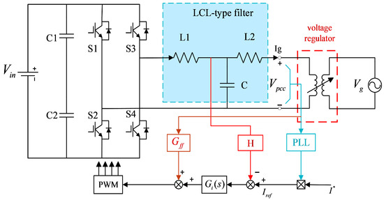
Figure 1.
Single-Phase Grid-Connected Inverter with LCL Filter.
2. System Model and Control
2.1. The Working Principle of SOGI
The structural block diagram of the conventional second-order generalized integrator (SOGI) is shown in Figure 2.
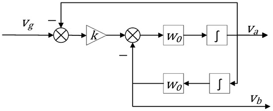
Figure 2.
Block Diagram of SOGI.
The orthogonal signal generated from the grid voltage input leads to the derivation of the closed-loop transfer function of the SOGI as follows:
Here, is the resonant frequency of the SOGI, represents the input grid voltage, and denotes the damping coefficient. When the resonant frequency matches the frequency of the input voltage, the component aligns with the fundamental component of in both phase and amplitude, while exhibits a 90° phase shift, thereby yielding two orthogonal signals and .
As shown in Figure 3, the damping coefficient (e.g., 0.5, 1.414, and 2) determines the bandwidth of the transfer function. From Figure 3a, it can be observed that behaves as a band-pass filter. A smaller results in a narrower bandwidth, leading to greater attenuation of DC components and improved filtering performance. However, this also slows the system response and increases its sensitivity to the resonant frequency . Figure 3b shows that acts as a low-pass filter, offering minimal attenuation for signals below the fundamental frequency. Therefore, a proper value of must be selected to balance these trade-offs. It is noteworthy that component can extract the fundamental component containing DC offset and harmonics from the grid voltage, while component effectively extracts the fundamental component from harmonics and noise. However, near 0 Hz, the magnitude response of the system exhibits a non-zero gain (close to the constant k), indicating that this structure cannot effectively suppress DC offset present in the input voltage. As a result, the output signal suffers from offset errors, which further affect phase accuracy [22].
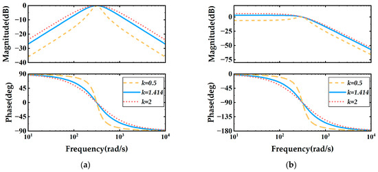
Figure 3.
Frequency response (Bode plots) of the transfer functions and under varying damping coefficients = 0.5, 1.414, 2. (a) Magnitude and phase of ; (b) Magnitude and phase of .
2.2. The Working Principle of the EA-SOGI
To suppress oscillations caused by DC bias in the input voltage and address the DC offset issue in single-phase PLLs, an innovative approach is proposed that integrates a DC offset estimation module with an all-pass filter (APF) into the conventional SOGI structure. The incorporation of the DC offset estimation module significantly enhances the accuracy and capability of estimating and suppressing the DC component in the input signal. The combination of SOGI and APF enables 90-degree phase delay correction without introducing any amplitude distortion. This leads to the construction of a novel pre-filtering structure, as illustrated in Figure 4.
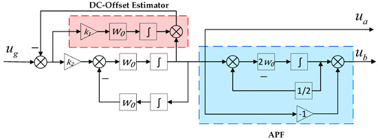
Figure 4.
Block Diagram of EA-SOGI.
The transfer function of the EA-SOGI can be expressed as:
The Bode plot of EA-SOGI, derived from Equations (3) and (4), is illustrated in Figure 5. A comparison between (Figure 3a) and (Figure 5a) reveals that exhibits a wider passband and a smoother phase curve. While preserving the fundamental filtering capabilities, it significantly enhances the steady-state accuracy and dynamic stability of the system. A comparison between and indicates that the system order has increased by two, effectively forming a fourth-order pre-filter. By examining the transfer function of , it can be observed that becomes zero when . This implies that is capable of completely rejecting DC components. Hence, the ability to suppress DC offset has fundamentally improved—from being absent to fully implemented.
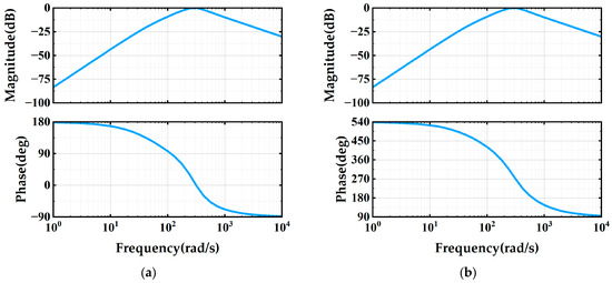
Figure 5.
Bode diagram of the EA-SOGI with parameters = 0.15 and = 1. (a) Magnitude and phase of ; (b) Magnitude and phase of .
2.3. Analysis of DC Offset Rejection in EA-SOGI
Suppose the input grid voltage is a biased sinusoidal signal containing a DC offset, which can be expressed as:
represents the DC offset in the input voltage, and the initial phase angle is denoted as . In the Laplace domain, can be expressed by the following equation:
Observing Equations (7) and (8), it can be seen that both numerators contain the Laplace variable with an order higher than one, indicating high-pass characteristics for the DC component . As a result, the steady-state output contains no DC offset, and it is only necessary to evaluate the complex gain for the fundamental component .
Evaluate the denominator of at :
where
The fourth-order denominator of is calculated as follows:
Frequency-domain characteristics of the numerator transfer function in each path:
:
:
Based on this, two sets of magnitude and phase characteristics are obtained.
It can be observed that the magnitude attenuation satisfies . Likewise, the phase response satisfies , when , the phase lags by approximately 90 degrees.
By applying Laplace transform techniques to Equations (7) and (8), the steady-state output of can be expressed as:
The magnitude mmm is given by Equations (15) and (16), with the DC component completely eliminated. The phase shift consists of the initial phase angle , plus the inherent phase angle of each numerator, where :
Equation (18) confirms that orthogonal α-axis and β-axis components are precisely formed within the PLL.
In conclusion, by incorporating an additional integrator, the system introduces a high-pass characteristic that completely rejects DC components, ensuring that no steady-state bias propagates into the phase detection. Meanwhile, the all-pass filter preserves the signal amplitude while correcting phase delay, thereby maintaining accurate 90° orthogonality between the α and β signals. When considering the parameters and in the transfer function of the EA-SOGI, it can be seen from Equation (17) that they have no impact on the steady-state behavior. However, the values of and do influence the transient response and the harmonic attenuation capability of the EA-SOGI filtering block. Therefore, proper tuning of and is essential to ensure satisfactory performance, which will be discussed in detail in the following section.
2.4. Quasi-Proportional Resonant (QPR) Control
In order to improve the control performance of the PI controller within the PLL, the controller can be optimized accordingly. As mentioned in [23], the Proportional-Resonant (PR) controller provides infinite gain at the fundamental frequency and enables zero steady-state error tracking for sinusoidal AC signals. The transfer function of the PR controller is given as follows:
where is the proportional gain, is the resonant gain, and denotes the nominal (fundamental) angular frequency.
The proportional-resonant (PR) controller exhibits extremely high gain at the nominal frequency, enabling zero steady-state error tracking for sinusoidal AC signals. However, when the grid voltage frequency suddenly changes, the controller’s gain decreases rapidly, leading to degraded current tracking performance in grid-connected applications. To overcome this issue, a cutoff frequency is introduced to widen the PR controller’s bandwidth. This results in the design of a quasi-proportional-resonant (QPR) controller, whose transfer function is defined as follows:
where is the proportional gain, is the resonant gain, is the fundamental frequency, and denotes the cutoff frequency.
Figure 6 presents the Bode plot of the QPR controller with selected parameters: fundamental frequency , , , and cutoff frequency . It is evident that the gain of the QPR controller decreases significantly in the high-frequency region, indicating its effectiveness in suppressing noise components beyond the nominal frequency while maintaining system stability. Compared with PI and conventional PR controllers, the QPR controller provides improved accuracy in handling frequency and phase deviations, thereby reducing phase lag without compromising the system’s overall stability.
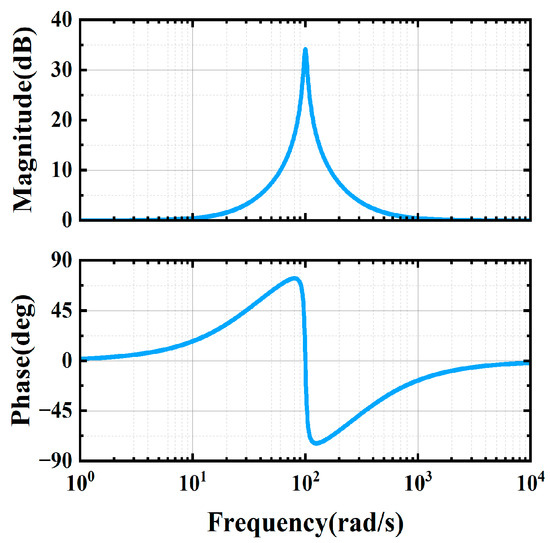
Figure 6.
Bode diagram of the QPR controller.
3. Parameter Optimization
To enhance the dynamic response and frequency tracking capability in single-phase phase-locked loop (PLL) systems, this study employs a quasi-proportional-resonant (QPR) controller structure. The key parameters in the design of this controller include the proportional gain , the resonant gain , and the cutoff frequency . Additionally, two tuning parameters and are embedded in the enhanced all-pass structure second-order generalized integrator (EA-SOGI) module. These parameters significantly affect the system’s dynamic performance, steady-state error, and adaptability to frequency deviations. Therefore, an optimization algorithm is required to automatically identify the optimal combination of these parameters.
3.1. Principle of the Asynchronous Linearly Changing Learning Factor Particle Swarm Optimization Algorithm (AsyLnCPSO)
Particle Swarm Optimization (PSO) is a swarm intelligence optimization algorithm inspired by the foraging behavior of bird flocks. In the standard PSO, each particle updates its position based on its own best-known position (Pbest) and the global best-known position (Gbest) among all particles. The search behavior is governed by the following equations:
Here, denotes the inertia weight, and are learning factors, and are uniformly distributed random numbers in the range [0, 1]. Although this method has a simple structure, the fixed learning factors may cause the search behavior to be overly aggressive in the early stages and lack local search capability in later stages. This makes the algorithm prone to premature convergence, especially in non-convex or high-dimensional search spaces. To address these issues, the Asynchronous Linear Changing Cognitive and Social Learning Factors PSO (AsyLnCPSO) algorithm is proposed to dynamically adjust and :
The cognitive component decreases over time, encouraging individual exploration in the early stages, while the social component increases, promoting collective convergence in the later stages. This asynchronous mechanism enhances the algorithm’s adaptability across different phases, enabling stronger global exploration in the initial stage and improved convergence performance in the later stage.
3.2. Levy Flight Mechanism
Levy flight is a random step-length model characterized by a heavy-tailed distribution, commonly used to model sudden, long-distance jumps. It is distinguished by the presence of predominantly short steps punctuated by occasional long jumps, conforming to a Levy distribution:
Compared to the conventional Gaussian distribution, the Levy distribution is more suitable for modeling non-local search processes. It is commonly approximated using the Mantegna algorithm:
Variables and follow Gaussian distributions , respectively. The introduction of the Levy flight mechanism can effectively help particles escape from local optima and enhance the global search capability of the algorithm.
3.3. Levy–AsyLnCPSO Hybrid Strategy
To fully leverage the strengths of AsyLnCPSO and the Lévy flight mechanism, this paper integrates both into a novel optimization algorithm named Levy–AsyLnCPSO. Based on the original AsyLnCPSO framework, a Lévy perturbation term is introduced after the velocity update. During each iteration, particles perform a Lévy jump to expand the search space and avoid entrapment in local optima. The position update equation is expressed as follows:
Here, denotes the personal best position of the particle, represents the global best position, and signifies the Levy perturbation term.
To further clarify the operational steps of the proposed Levy–AsyLnCPSO algorithm, Figure 7 illustrates its overall flow. The algorithm begins by initializing the decision vector within feasible bounds. In each iteration, asynchronous learning schedules are adopted to dynamically adjust the cognitive and social learning factors, which ensures stronger exploration in the early stage and improved convergence in the later stage. Based on this schedule, particles update their velocities and positions according to the standard AsyLnCPSO rules. To avoid premature convergence, a Levy perturbation is injected with a certain probability after the position update, thereby introducing occasional long jumps and enlarging the search space. After boundary handling, the updated particles are evaluated through the PLL simulation model to obtain their fitness values. The algorithm then updates the personal and global best solutions. This process repeats until the maximum number of iterations or a convergence criterion is satisfied, after which the optimal parameter set is obtained.
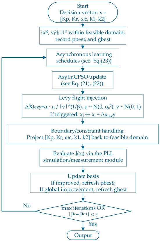
Figure 7.
Flowchart of the Levy–AsyLnCPSO Algorithm.
3.4. Algorithm Evaluation
To verify the effectiveness of the improved algorithm, PSO, AsyLnCPSO, and Levy-AsyLnCPSO were used to perform comparative tests on four internationally recognized benchmark functions. In the experiments, all algorithms were initialized with a population size of 30 and a maximum number of 1000 iterations. The theoretical optimal value for all functions is 0. Details of the benchmark functions are listed in Table 1.

Table 1.
Benchmark Function Information.
As observed from Figure 8, the conventional PSO demonstrates the slowest convergence and poorest accuracy, often stagnating at suboptimal values. AsyLnCPSO improves convergence speed and accuracy by dynamically adjusting the cognitive and social learning factors, but it can still become trapped in local optima, especially for multimodal functions. In contrast, Levy–AsyLnCPSO consistently achieves both faster convergence and better accuracy across all benchmark functions.
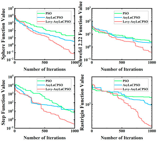
Figure 8.
Benchmark Function Comparison Charts.
This advantage arises from the Levy flight mechanism, which introduces occasional long jumps into the particle trajectories. For unimodal functions such as Sphere and Schwefel, these jumps enlarge the search radius during early iterations, enabling quicker global convergence. For multimodal functions such as Step and Rastrigin, the long jumps help particles escape local minima, thereby preventing premature convergence and achieving solutions closer to the global optimum.
Table 2 further confirms these observations: the Levy–AsyLnCPSO achieves errors very close to zero in all cases, while PSO and AsyLnCPSO show larger deviations.
Table 2.
Algorithm Performance Comparison.
Overall, the integration of Levy flights with AsyLnCPSO significantly enhances robustness and global exploration ability, making the hybrid algorithm well suited for optimizing PLL controller parameters, where the search space is nonlinear and multimodal.
3.5. Performance Comparison and Analysis of Algorithms
To quantitatively evaluate the effectiveness of the proposed algorithm in optimizing parameters within the SOGI system, this paper conducts comparative experiments using the final parameter sets obtained from three different particle swarm optimization (PSO) strategies. The comparison is conducted across the following three key performance metrics:
- 1.
- Fundamental Amplitude Error;This metric characterizes the amplitude discrepancy between the alpha-axis and beta-axis components extracted by the SOGI. It is calculated as the sum of squared differences between the magnitudes of the fundamental frequency components in both channels:where and are the complex coefficients of the fundamental frequency components of and , respectively, and is the reference amplitude (normalized to 1).
- 2.
- Orthogonal Phase Error;This metric reflects the phase deviation between signals and . Ideally, the phase difference should be ±90°. In this paper, the phase deviation is calculated based on the phase difference in the dominant frequency components in the frequency domain:
- 3.
- Phase-Locking Time.This metric represents the shortest time required for the phase angle error in the PLL system to converge within ±0.5° and remain stable for at least 10 ms. It serves as an indicator of the system’s dynamic response speed.
As summarized in Table 3, the improvements brought by the Levy–AsyLnCPSO optimization are not only numerical but also practically meaningful for real-time PLL applications.
Table 3.
Comparison of Algorithm Performance.
First, the amplitude error is reduced from 0.0592 (PSO) to 2.4 × 10⁻⁴, indicating that the orthogonal α and β components remain highly symmetrical, which is crucial for accurate coordinate transformation. Second, the orthogonal phase error decreases from 1.7 × 10⁻³ to the order of 10−12, demonstrating nearly ideal 90° orthogonality and ensuring precise phase estimation even under distorted grid conditions. Finally, the phase-locking time is shortened from 64.5 ms (PSO) to about 30 ms, which satisfies the common requirement of grid-connected inverters that synchronization should be achieved within 50 ms.
These results confirm that the Levy–AsyLnCPSO-based parameter tuning significantly enhances both accuracy and dynamic response, making the proposed PLL suitable for practical implementation.
The final optimized parameters obtained via the Levy-AsyLnCPSO algorithm are , , , , .
4. Simulation and Experimental Analysis
To validate the effectiveness of the proposed improved PLL control structure, a comprehensive single-phase grid-connected simulation model was established in MATLAB/Simulink, employing a single-loop feedback control based on the inverter-side current.
4.1. Simulation Analysis
We analyze the performance of the conventional SOGI, Type-3 SOGI [24], APF-SOGI, and the proposed EA-SOGI in terms of output frequency and current waveforms during grid synchronization, as illustrated in Figure 9.
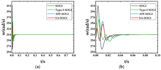
Figure 9.
Angular Frequency Waveforms of Different QSGs: (a) Angular Frequency; (b) Enlarged View of the Initial Response.
From Figure 9, it can be observed that the conventional SOGI exhibits large frequency oscillations in the initial stage, indicating poor stability and a long recovery time. Both the Type-3 SOGI and the APF-SOGI show certain overshoot at the beginning, whereas the EA-SOGI demonstrates no noticeable overshoot, maintains a smooth response, and locks the frequency at 50 Hz within a much shorter time.
To evaluate the harmonic suppression capability of different PLL structures in grid-connected current control, time-domain and frequency-domain analyses were performed on the current signals under NO-PLL, SOGI, Type-3 SOGI, APF-SOGI, and EA-SOGI configurations. Quantitative comparisons were conducted focusing on DC offset (0 Hz), third harmonic (150 Hz), and total harmonic distortion (THD), as illustrated in Figure 10.
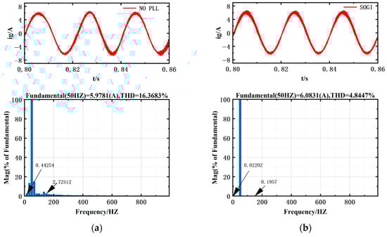
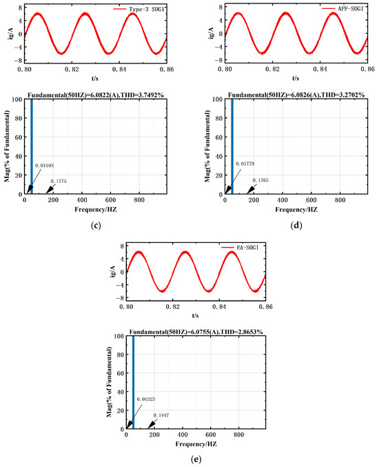
Figure 10.
Grid-Connected Inverter Current Waveforms and FFT Analysis: (a) NO-PLL; (b) SOGI; (c) Type-3 SOGI; (d) APF-SOGI; (e) EA-SOGI.
Figure 10 illustrates the differences in output current waveforms and harmonic content among various structures.
Without a PLL, the inverter current directly follows the distorted grid voltage, resulting in a significantly high total harmonic distortion (THD = 16.37%), a DC component of 0.4425% at 0 Hz, and a third-order harmonic of 2.73% at 150 Hz.
By introducing a PLL, the system can generate orthogonal components and more accurately extract the fundamental signal, thereby inherently suppressing DC offsets and harmonics.
Among the different methods, the conventional SOGI reduces part of the distortion through resonant filtering but remains sensitive to DC bias, leaving relatively high residual harmonics. The Type-3 SOGI and APF-SOGI, by employing additional phase-compensation branches, further mitigate the DC offset but still exhibit certain overshoot during the transient stage. In contrast, the proposed EA-SOGI, which integrates an all-pass filter and an additional integral path, achieves complete suppression of the DC component and produces smoother orthogonal signals. As a result, it achieves the lowest distortion level, with THD reduced to 2.8653%, DC component to 0.0132%, and third harmonic to 0.1447%.
To evaluate the dynamic performance and stability of the proposed method, several adverse operating conditions—including voltage sag, frequency deviation, phase jump, and DC offset—were simulated on the basis of an ideal grid voltage of 220 V/50 Hz, in order to verify the adaptability of the PLL. The corresponding simulation results are presented in Figure 11.
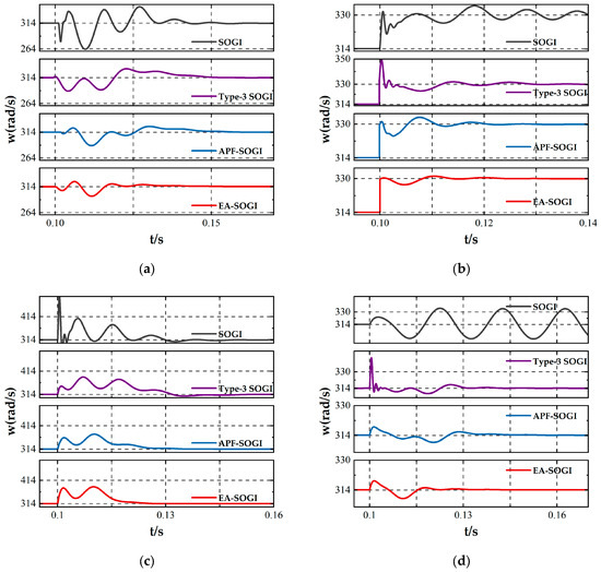
Figure 11.
QSG responses under different conditions: (a) voltage sag of 0.5 p.u., (b) frequency increase of 2.5 Hz, (c) phase jump of 45°, (d) DC offset injection.
Figure 11a shows the case where the input voltage drops by 0.5 p.u. at 0.1 s. All PLLs undergo a transient adjustment process, during which the conventional SOGI exhibits strong oscillations and a long recovery time. In contrast, the proposed EA-SOGI achieves a smooth transition with only a small overshoot and recovers within 0.04 s.
Figure 11b illustrates the response to a sudden frequency increase of 2.5 Hz at 0.1 s. The conventional SOGI oscillates severely around the new equilibrium at 52.5 Hz, while the Type-3 SOGI converges more quickly but suffers from noticeable overshoot. The EA-SOGI completes frequency tracking the fastest with the smallest oscillation amplitude, demonstrating that the improved structure effectively mitigates phase errors induced by frequency deviations.
Figure 11c presents the case of a 45° phase jump applied at 0.1 s. The EA-SOGI exhibits superior performance by resynchronizing first, whereas the Type-3 SOGI, due to the introduction of additional compensation branches, shows a longer settling time.
Figure 11d depicts the injection of a DC offset into the single-phase input voltage at 0.1 s. The conventional SOGI fails to reject the DC component and results in sustained oscillations, whereas the EA-SOGI, aided by the additional integrator and compensation path, nearly eliminates the impact of the DC bias and maintains stable frequency estimation.
In summary, the EA-SOGI not only provides high accuracy under steady-state conditions but also demonstrates superior robustness and adaptability under adverse scenarios such as voltage sags, frequency deviations, phase jumps, and DC offsets, validating its reliability in practical grid-connected PLL applications.
4.2. Physical Experiment
To validate the reliability of the experimental results, a custom-designed 1 kW photovoltaic grid-connected inverter platform developed by a domestic company was employed, as illustrated in Figure 12. During testing, the grid frequency was aligned with that of a specific district in Shenyang, Liaoning Province. A rapid control prototyping (RCP) unit (YXSP2000) was used to acquire the current signals, which were then processed on a personal computer for Orthogonal Component Filtering (OCF) and signal detection. The experimental setup employed the TI TMS320F28335 platform with a built-in 12-bit ADC. The quantization error is less than 0.05% of the full-scale input, which is negligible compared to the system operating range. Measurement noise was further mitigated by digital sampling and filtering, while the intrinsic low-pass characteristics of the PLL suppress high-frequency disturbances. The inverter adopts the SPWM modulation strategy with a switching frequency of 20 kHz, and the detailed parameters are listed in Table 4.
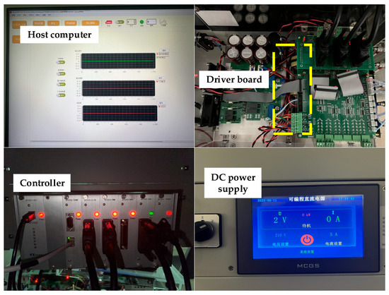
Figure 12.
Experimental Platform.
Table 4.
System Physical Parameters.
As shown in Figure 13, the angular frequency waveforms demonstrate that the EA-SOGI is still capable of effectively locking the phase in hardware implementation. In particular, Figure 13b shows that during the initial grid-connection stage, both SOGI and Type-3 SOGI exhibit significant frequency oscillations, while EA-SOGI displays the smallest oscillation amplitude, indicating its superior response speed and robustness. As illustrated in Figure 13c, the SOGI exhibits large frequency fluctuations during the later stages of operation, which significantly deviates from the simulation results. The primary reason for this discrepancy lies in the difference between the simulation and the actual hardware environment. In the simulations, the grid voltage frequency is fixed at 50 Hz, whereas in the hardware experiments, the real utility grid was used, which fluctuates slightly around 50 ± 0.1 Hz. At this point, due to the insufficient frequency adaptability of SOGI, it fails to effectively track these slight fluctuations, resulting in increased oscillation amplitude. This reveals that SOGI is relatively sensitive to frequency disturbances under actual grid conditions [25]. The improved EA-SOGI, through the combination of an additional integrator and an all-pass filter, is still able to accurately lock the phase in hardware experiments, with only minor deviations from the simulation results.
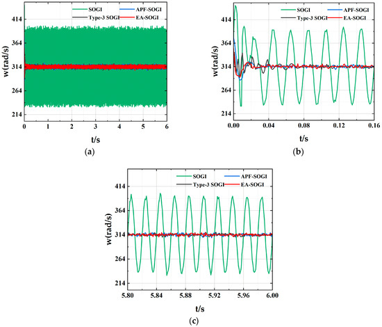
Figure 13.
Angular Frequency Waveform (a) Angular Frequency (b) Early-Stage Zoom-In View (c) Late-Stage Zoom-In View.
As shown in Figure 14a, without the Phase-Locked Loop (PLL), the system appears to have a faster response and better steady-state performance. However, in this case, the harmonic components of the grid voltage are directly passed to the reference current, causing distortion in the inverter output current waveform and a phase error of 16.2°, which negatively affects the grid quality. As shown in Figure 14b, after introducing the EA-SOGI PLL, the phase error is reduced to 8°, and the waveform distortion is significantly reduced. This demonstrates that the EA-SOGI can significantly improve current tracking performance under steady-state conditions, enhancing the system’s power factor and grid connection quality.
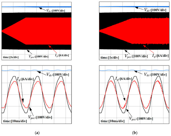
Figure 14.
Grid voltage and grid-connected current waveforms: (a) Without the PLL (b) With the EA-SOGI PLL introduced.
As shown in Figure 15, the fast Fourier transform (FFT) analysis of the inverter output current under the hardware environment is presented. In the absence of a PLL, the total harmonic distortion (THD) reaches 7.514%, with a DC component proportion of 0.14821% at 0 Hz and a third harmonic component of 7.28879% at 150 Hz (Figure 15a). After introducing SOGI, although some suppression of DC offset and harmonics is achieved, the output current waveform still exhibits significant distortion (Figure 15b). This discrepancy is primarily attributed to differences between the simulation and hardware environments: in simulations, the grid voltage frequency is assumed to be an ideal sinusoidal waveform, whereas in real hardware conditions, the utility grid inevitably includes harmonic distortions and DC offset components. Furthermore, in simulation models, pure inductance is typically connected on the grid side to emulate grid impedance. In contrast, the actual hardware environment involves a variety of components such as cables and transformers, leading to a grid impedance that is generally lower than the value used in simulations. Type-3 SOGI and APF-SOGI possess better adaptability than SOGI, enabling them to maintain a certain level of harmonic suppression under fluctuating grid frequencies. However, due to structural limitations, the proportion of DC offset components remains relatively high (Figure 15c,d). EA-SOGI demonstrates the best performance in suppressing both harmonics and DC offset, achieving a THD of 3.7421%, with the DC component reduced to 0.01979% and the third harmonic component at 150 Hz lowered to 0.31235%, representing the lowest levels among all schemes (Figure 15e). This indicates that EA-SOGI maintains robust performance even under real hardware conditions. These results are largely consistent with simulation outcomes, thus validating the effectiveness of the proposed control strategy.
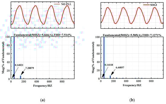
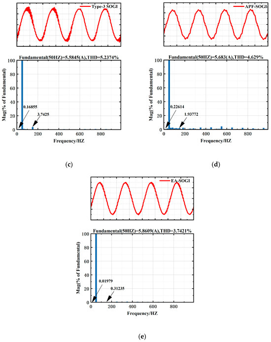
Figure 15.
Experimental Grid-Connected Current Waveforms and FFT Analysis (a) NO-PLL (b) SOGI (c) Type-3 SOGI (d) APF-SOGI (e) EA-SOGI.
5. Conclusions
This study focuses on single-phase grid-connected inverters, addressing key issues such as DC offset, harmonic interference, and the impact of phase-locked loops (PLLs) on system stability. The research primarily investigates PLL control strategies and controller parameter optimization. Based on comprehensive theoretical analysis, simulation verification, and hardware experiments, the following conclusions are drawn:
- To address the limitations of conventional SOGI-based PLLs in terms of DC offset suppression, harmonic rejection, and adaptive performance, this work proposes a structurally enhanced SOGI module. By incorporating a full-pass phase compensation channel and a DC offset rejection mechanism, the proposed EA-SOGI structure significantly improves the extraction accuracy of the fundamental signal. Additionally, the conventional PI controller in the PLL is replaced with a quasi-proportional-resonant (QPR) controller, which enhances the system’s dynamic response at resonant frequencies while maintaining zero steady-state error. Simulation and hardware experiment results confirm that the EA-SOGI structure exhibits superior performance in suppressing DC offset and reducing total harmonic distortion (THD), lowering THD to 2.8653%, thus validating its effectiveness in improving grid power quality.
- In terms of parameter tuning, this study adopts the Levy-AsyLnCPSO intelligent optimization algorithm to conduct multi-objective cooperative searching of the QPR controller’s resonance frequency, proportional gain, and resonant gain. This strategy achieves an optimal trade-off among system stability, dynamic response, and harmonic suppression. Simulation results demonstrate that the parameters optimized by Levy-AsyLnCPSO significantly enhance the synchronization accuracy and dynamic robustness of the single-phase grid-connected system, thereby ensuring its reliable operation.
Although the proposed EA-SOGI combined with the Levy–AsyLnCPSO optimization algorithm has demonstrated excellent performance in suppressing DC offset, improving frequency adaptability, and enhancing robustness under distorted grid conditions, there are still several promising directions for future research. First, the extension of the proposed method to three-phase systems and multi-converter scenarios will be investigated to evaluate its scalability in complex grid environments. Second, incorporating higher-order harmonic compensation and adaptive notch filters could further enhance the rejection of severe harmonic distortions. Finally, integrating the proposed PLL structure with advanced grid-forming and grid-following control strategies may provide additional insights into improving the stability of future renewable-rich power systems.
Author Contributions
Conceptualization, X.K.; writing—original draft preparation, X.X.; writing—review and editing, X.X. and G.G.; software, X.X.; funding acquisition, X.K. All authors have read and agreed to the published version of the manuscript.
Funding
This research was funded by the Liaoning Provincial Department of Education Basic Scientific Research Project, grant number LJKMZ20220778; and the National Foreign Expert Project of China, grant number DL2021006001L.
Data Availability Statement
The authors will provide the raw data supporting the conclusions of this article upon request.
Conflicts of Interest
The authors declare no conflicts of interest.
Abbreviations
The following abbreviations are used in this manuscript:
| PLL | Phase-Locked Loop |
| SOGI | Second-Order Generalized Integrator |
| EA-SOGI | Extended-State All-Pass Generalized Integrator |
| PI | Proportional-Integral |
| PR | Proportional Resonant |
| QPR | Quasi-Proportional Resonant |
| AsyLnCPSO | Asynchronous Linearly Varying Learning Factor Particle Swarm Optimization |
| FFT | Fast Fourier Transform |
| THD | Total Harmonic Distortion |
| SRF-PLL | Synchronous reference frame-based PLL |
| QSG | Quadrature signal generator |
| APF-SOGI | All-Pass Filter Based Second-Order Generalized Integrator |
References
- Lu, Q.; Yu, H.; Zhao, K.; Leng, Y.; Hou, J.; Xie, P. Residential demand response considering distributed PV consumption: A model based on China’s PV policy. Energy 2019, 172, 443–456. [Google Scholar] [CrossRef]
- Wei, T.; Pan, H.; Duan, Z.; Xie, P. New energy technology innovation and energy poverty alleviation in China. Renew. Energy 2024, 235, 121348. [Google Scholar] [CrossRef]
- Hou, L.; Zhu, C.; Chen, Y.; Yan, X. Research on SOGI for phase lock technique of the single-phase grid-connected system. Electr. Meas. Instrum. 2016, 53, 84–89. [Google Scholar]
- Routray, A.; Pradhan, A.K.; Rao, K.P. A novel Kalman filter for frequency estimation of distorted signals in power systems. IEEE Trans. Instrum. Meas. 2002, 51, 469–479. [Google Scholar] [CrossRef]
- Song, H.S.; Nam, K. Instantaneous phase-angle estimation algorithm under unbalanced voltage-sag conditions. IEE Proc.-Gener. Trans- Mission. Distrib. 2000, 147, 409–415. [Google Scholar] [CrossRef]
- Wu, Z.; Qin, F.; Yang, K. Design of phase-locked loop based on sliding discrete Fourier transform. Electr. Energy Manag. Technol. 2017, 6, 78–82. (In Chinese) [Google Scholar] [CrossRef]
- Chen, S.; Yi, L.; Huang, W.; Lin, W. Single-phase phase-locked technique based on con- structing non-orthogonal vector. Trans. China Electrotech. Soc. 2019, 34, 398–408. [Google Scholar]
- Golestan, S.; Guerrero, J.M.; Vidal, A.; Yepes, A.G.; Doval-Gandoy, J.; Freijedo, F.D. Small-signal modeling, stability analysis and design optimization of single-phase delay-based PLLs. IEEE Trans. Power Electron. 2015, 31, 3517–3527. [Google Scholar] [CrossRef]
- Akhtar, M.A.; Saha, S. An adaptive frequency-fixed second-order generalized integrator-quadrature signal generator using fractional-order conformal mapping based approach. IEEE Trans. Power Electron. 2020, 35, 5548–5552. [Google Scholar] [CrossRef]
- Cao, N.; Feng, W. Improved single-phase PLL based on all-pass filter. J. Phys. Conf. Series. 2023, 2477, 012060. [Google Scholar] [CrossRef]
- Rodriguez, P.; Luna, A.; Munoz-Aguilar, R.S.; Etxeberria-Otadui, I.; Teodorescu, R.; Blaabjerg, F. A stationary reference frame grid synchronization system for three-phase grid-connected power converters under adverse grid conditions. IEEE Trans. Power Electron. 2012, 27, 99–112. [Google Scholar] [CrossRef]
- Matas, J.; Martin, H.; De La Hoz, J.; Abusorrah, A.; Al-Turki, Y.A.; Al-Hindawi, M. A family of gradient descent grid frequency estimators for the SOGI filter. IEEE Trans. Power Electron. 2017, 33, 5796–5810. [Google Scholar] [CrossRef]
- Singh, B.; Kumar, S.; Jain, C. Damped-SOGI-based control algorithm for solar PV power generating system. IEEE Trans. Ind. Appl. 2017, 53, 1780–1788. [Google Scholar] [CrossRef]
- Stojić, D. Improved observer-based quadrature signal generator. Electr. Eng. 2021, 103, 3063–3073. [Google Scholar] [CrossRef]
- Modi, G.; Singh, B. Improved Cascaded SOGI Control for Islanding-Synchronization in Photovoltaic System. IEEE Trans. Ind. Appl. 2022, 58, 6909–6919. [Google Scholar] [CrossRef]
- Rong, C.; Chao, L. Design of single-phase phase-locked loop based on improved second-order generalized integrator. Process Autom. Instrum. 2020, 41, 51–55+67. (In Chinese) [Google Scholar]
- Zhang, Y.; Shen, Y.; Wang, T.; Cheng, T.; Chen, Z. An Improved SOGI-PLL for DC Offsets and Frequency Ramps. J. Electr. Eng. Technol. 2025, 20, 4231–4242. [Google Scholar] [CrossRef]
- Fawaz, B.H.B.; Smadi, I.A.; Albatran, S.A.; Atawi, I.E. Advanced Single-Phase PLL-Based Transfer Delay Operators: A Comprehensive Review and Optimal Loop Filter Design. Energies 2024, 17, 419. [Google Scholar] [CrossRef]
- Chakraborty, S.; Modi, G.; Singh, B.; Panigrahi, B.K.; Sanjenbam, C.D. Cascaded SOGI in-loop comb based enhanced phase estimation control for a battery less grid-tied SPVS during abnormal grid conditions. In Proceedings of the 2023 IEEE International Conference on Energy Technologies for Future Grids (ETFG), Wollongong, Australia, 3–6 December 2023; pp. 1–6. [Google Scholar]
- De Oliveira Evald, P.J.D.; Dall’Asta, M.S.; Schmitz, L.; de Andrade, J.M.; Lazzarin, T.B. Generalizable adaptive controller for grid-connected inverters with long transmission cables. Electr. Power Syst. Res. 2025, 247, 111786. [Google Scholar] [CrossRef]
- Chakraborty, S.; Patel, S.; Salapaka, M.V. Design of H-infinity-based Robust Controller for Single-phase Grid-feeding Voltage Source Inverters. arXiv 2020, arXiv:2008.10708. [Google Scholar]
- Liu, B.; An, M.; Wang, H.; Chen, Y.; Zhang, Z.; Xu, C.; Song, S.; Lv, Z. A simple approach to reject DC offset for single-phase synchronous reference frame PLL in grid-tied converters. IEEE Access 2020, 8, 112297–112308. [Google Scholar] [CrossRef]
- Zhou, W.; Xu, X.; Tan, S.; Mao, L.; An, M.; Luo, C. Research on Parallel Control Technology of Three-phase Inverter Based on Multiple Proportional Resonance Controller. J. Phys. Conf. Ser. 2020, 1549, 052129. [Google Scholar] [CrossRef]
- Prakash, S.; Singh, J.K.; Behera, R.K.; Mondal, A. A type-3 modified SOGIPLL with grid disturbance rejection capability for single-phase grid-tied converters. IEEE Trans. Ind. Appl. 2021, 57, 4242–4252. [Google Scholar] [CrossRef]
- Shi, W.; Yu, J.; Zhou, R. A zero-tracking SOGI-based frequency-locked loop. IEEE J. Emerg. Sel. Top. Power Electron. 2021, 10, 3114–3128. [Google Scholar] [CrossRef]
Disclaimer/Publisher’s Note: The statements, opinions and data contained in all publications are solely those of the individual author(s) and contributor(s) and not of MDPI and/or the editor(s). MDPI and/or the editor(s) disclaim responsibility for any injury to people or property resulting from any ideas, methods, instructions or products referred to in the content. |
© 2025 by the authors. Licensee MDPI, Basel, Switzerland. This article is an open access article distributed under the terms and conditions of the Creative Commons Attribution (CC BY) license (https://creativecommons.org/licenses/by/4.0/).