1. Introduction
With the continuous advancement of petroleum technology and the depletion of conventional oil and gas resources, there has been a growing emphasis on the exploration and development of unconventional resources, including deep marine carbonate reservoirs [
1], tight sandstone gas reservoirs [
2], and shale gas reservoirs [
3].
Due to their deep burial, the likelihood of encountering naturally fractured strata and induced well fractures is significantly heightened. For instance, in northeastern Sichuan, China, due to intricate geological conditions [
4], drilling operations frequently encounter complex downhole incidents such as drilling fluid losses. Statistical data reveal that nearly all wells in this region have experienced varying degrees of lost circulation; consequently, addressing lost circulation amplifies non-production time by 5% while adding over USD one million in extra costs per well [
4]. The loss of drilling fluid within fractured formations has substantially escalated the expenses associated with constructing deep unconventional resources. Simultaneously, in fractured reservoirs, the majority of oil and gas preferentially flows into the wellbore via fractures, which play a pivotal role in production capacity. However, it is noteworthy that drilling and completion fluids are susceptible to infiltrating the reservoir through these fractures, leading to solid-phase invasion and liquid-phase trap damage, thereby significantly compromising development effectiveness [
5].
When fracture-induced loss occurs during the drilling process, the following treatments can be adopted depending on the equipment and severity of the loss in drilling filed: drill through the lost circulation formation rapidly and then install a technical casing for cementing to permanently seal off the lost circulation formation. Conduct fracture plugging operations by injecting multiple lost circulation materials (LCMs) such as particles, resins, and cement slurries into the fractures around the wellbore to seal the fractures to prevent drilling fluid loss. Transform the drilling technology to underbalanced drilling, reducing the wellbore pressure below the formation pressure, converting severe loss into overflow, and overall reducing the engineering risk through surface well control. Perform sidetracking or abandon the well to avoid this formation prone to loss in subsequent drilling operations.
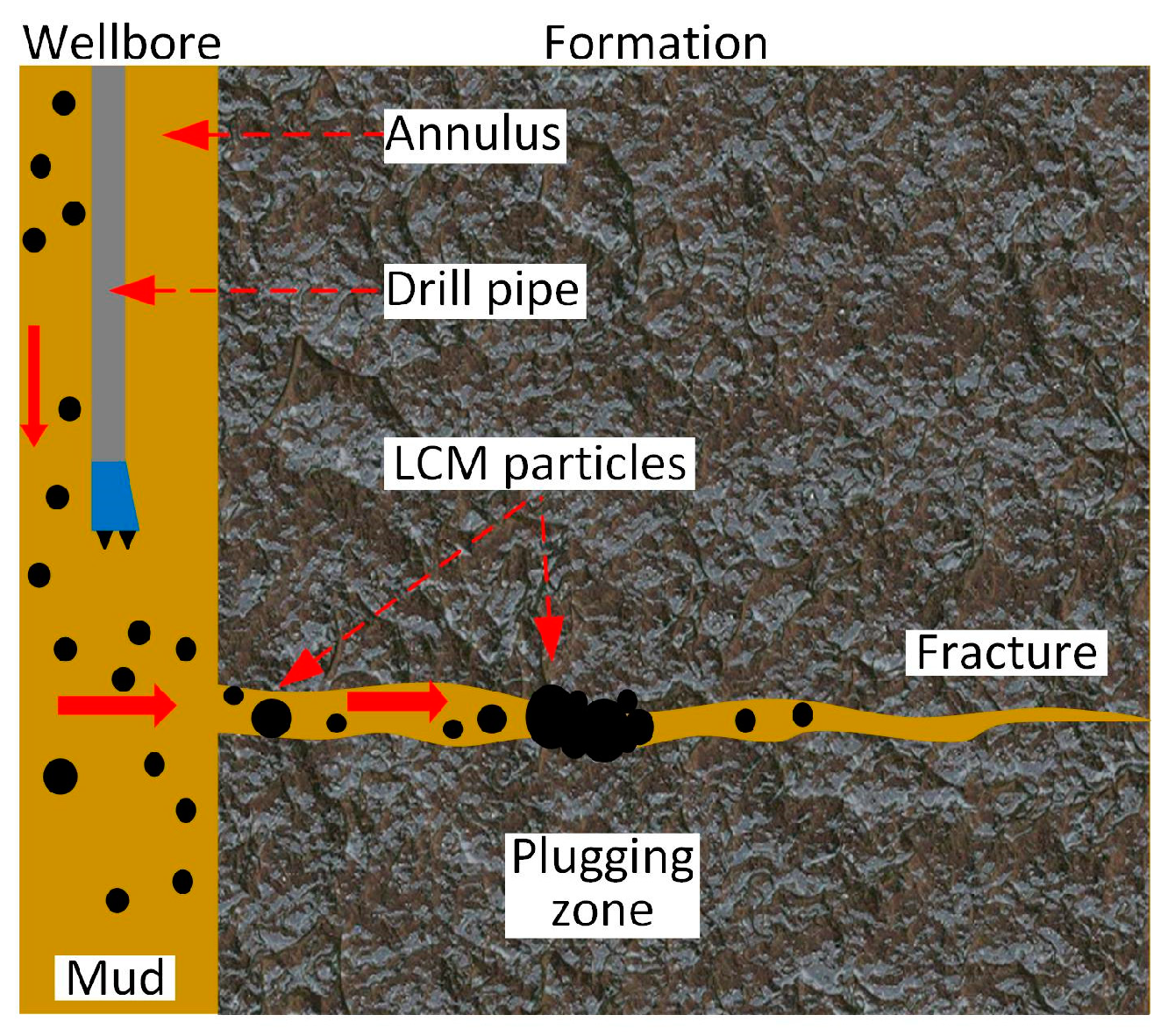
As shown in
Figure 1, the conventional treatment in drill fields involves incorporating solid particles such as rigid particles, fibers, and elastic particles into the drilling fluid to address lost circulation [
6]. These solid particles, referred to as LCM, will be carried along with the lost drilling fluid, and will then bridge and accumulate in fractures near the wellbore, effectively sealing them and preventing further loss of drilling fluid. The judicious selection of LCM composition and injection technique is crucial for achieving efficient and stable fracture plugging. Additionally, in fractured reservoirs, fractures serve as high-speed conduits for oil and gas flow. Therefore, it becomes imperative to control the depth of LCM intrusion by means of acidification prior to production in order to remove any obstructions caused by them [
7]. Ideally, the LCM should rapidly form a coherent and compact plugging zone within the shallow section of the fracture.
Taking cost into consideration, waste materials that have been processed into various shapes and sizes are commonly utilized as LCM. The shapes of LCM include granular [
8], flake [
9], and fibrous [
10]. Granular materials commonly employed consist of walnut shells, peanut shells, rubber granules, perlite granules, etc. These materials primarily function as “bridges” at the throat of fractures to facilitate plugging. Fibrous materials encompass polypropylene fiber, carbon fiber, sawdust, cotton fiber, flax fiber and waste brown rope, which enhance the strength of the plugged zone. Sheet-like materials comprise mica flakes, chaff, and cellophane, which rapidly occlude pores within the plugged zone. With the accumulation of experimental and drilling expertise, gel and polymer materials [
11] and reticulated foam materials [
12], as well as serrated metal particles [
13], have been incorporated as LCM.
In the drilling field fracture plugging operations, different types and sizes of LCM always were mixed and injected into the downhole simultaneously. This practice arises from the challenge of accurately determining fracture apertures during instances of drilling fluid loss. Often, only an approximate estimation can be made based on the severity of fluid losses. By injecting various sizes of LCM concurrently, it is possible to effectively plug fractures without precise knowledge of their actual apertures. Furthermore, once larger particles establish a bridge within the fracture, smaller particles can progressively fill in pore spaces layer by layer, thereby rendering the plugging zone increasingly impermeable.
Before being applied to the drilling field, the fracture plugging capacity of the above materials were mainly evaluated by laboratory fracture plugging experiments. When drilling fluid loss occurs, the wellbore fluid pressure is higher than the formation fluid pressure. So, the closer the fractured area to the wellbore, the more it will open, which makes the fracture wedge-shaped. Many experimental devices usually use two flat steel plates to simulate the wedge-shaped fracture flow space [
14,
15]. During the experiment, the drilling fluid mixed with LCM will be injected into the fracture flow space, and whether the fracture is plugged can be judged by measuring the fluid outflow rate at the outlet of the device. By opening the two steel plates after the experiment, the distribution of the plugging zone can be observed. A few experimental devices can also measure the resistance at different positions of the steel plate to roughly determine the formation position and development process of the plugging zone during the experiment. For these experimental devices and methods, firstly, there is a difference in surface morphology between the steel plate and the actual rock fracture, and secondly, it is impossible to observe the LCM migration, bridging and plugging process in the fracture in real time.
In contrast to the above-mentioned traditional experimental methods, Razavi [
16] used hydraulic fracturing to induce fractures on sandstone cores first, and then carried out a fracture plugging experiment. After the fracture was plugged, the resin was injected to make a thin section to observe the LCM distribution in the fracture. The flow space of the hydraulic fracturing fracture in this method was consistent with the actual near-wellbore fractures, not the smooth and regular wedge-shaped flow space. However, the fracture plugging process still cannot be observed in real time. Raimbay [
17], Huang [
18], Huang [
19] and Huang [
20] used transparent resin to mold the fracture plates that contain the actual rough fracture surface, and then a series of visual experiments were carried out on these fracture plates to observe the proppant displace process in the rough fracture. The above two methods provide the possibility of studying the LCM migration, bridging and plugging process in the fracture, but further improvement is still needed.
In recent years, numerous researchers have conducted visual experiments to study the migration process of particles in fractures. To investigate the sand-carrying capacity of water-based fracturing fluids, Li [
21] constructed a visual sand-carrying device and directly observed the proppant placement in the fractures. In our previous studies [
22,
23], in order to investigate the influencing factors of the LCM bridging mode, a visualization experimental apparatus for fracture plugging was fabricated, and its irregular fracture space was consistent with that of actual rock fractures. Xu [
24] used a micro-visualization experimental device for the formation of a fracture plugging zone to analyze the plugging behavior of irregular-shaped LCM with different types and concentrations in fractures.
In drilling sites and previous studies, different sizes and types of LCM are all mixed on the ground and simultaneously injected into the wellbore, and then enter the fractures near the wellbore. However, there remains a gap in research regarding the effectiveness of different LCMs under this simultaneous injection approach and whether alternative injection methods could yield greater efficiency. In this study, we established a visualization experimental method for investigating differences between simultaneous injection and graded multiple injections concerning their efficacy in fracture plugging.
2. Fracture Plugging Visualization Experimental Method
2.1. Overview
In this paper, a high-resolution scanner is used to obtain the topography data of both sides of carbonate fracture, and the corresponding computer three-dimensional model is established. Then, based on the model, a high-precision engraving machine is used to process the fracture surface on two transparent PMMA (Polymethyl Methacrylate) plates. After assembly, a transparent fractured module is built up, and the fracture aperture of this module is consistent with the scanned carbonate fracture. In the fracture plugging visualization experiment, the solution mixed with purple particles of specific size will be injected into the module to simulate the process of the LCM plugging the near-wellbore fracture.
The visualization experiment of fracture plugging in this paper primarily focuses on selecting suitable experimental fluids and flow pressure differentials, as well as ensuring that the flow space characteristics of the fractures are comparable to those of actual rock fractures, to simulate the actual plugging process on the site. In contrast to the plugging operations on the drilling site, this study emphasizes the early migration and bridging process of the plugging particles within the fractures rather than the ultimate pressure-bearing capacity of the LCM. The research herein contributes to understanding the mechanism of the fracture plugging process and its influencing factors. More details are shown below.
2.2. Modeling of Actual Rock Fracture Flow Space
The rock samples were collected from the outcrop of the carbonate rock strata in Wangcang, Sichuan Province, China. After being cut into cubic rock block with a side length of 30 cm in the field, they were transported back to the laboratory. There was an incomplete fracture inside the rock block. After the fracture was pried open in the laboratory, two rock blocks with natural irregular fracture surfaces were obtained, one on top and the other at the bottom.
As shown in
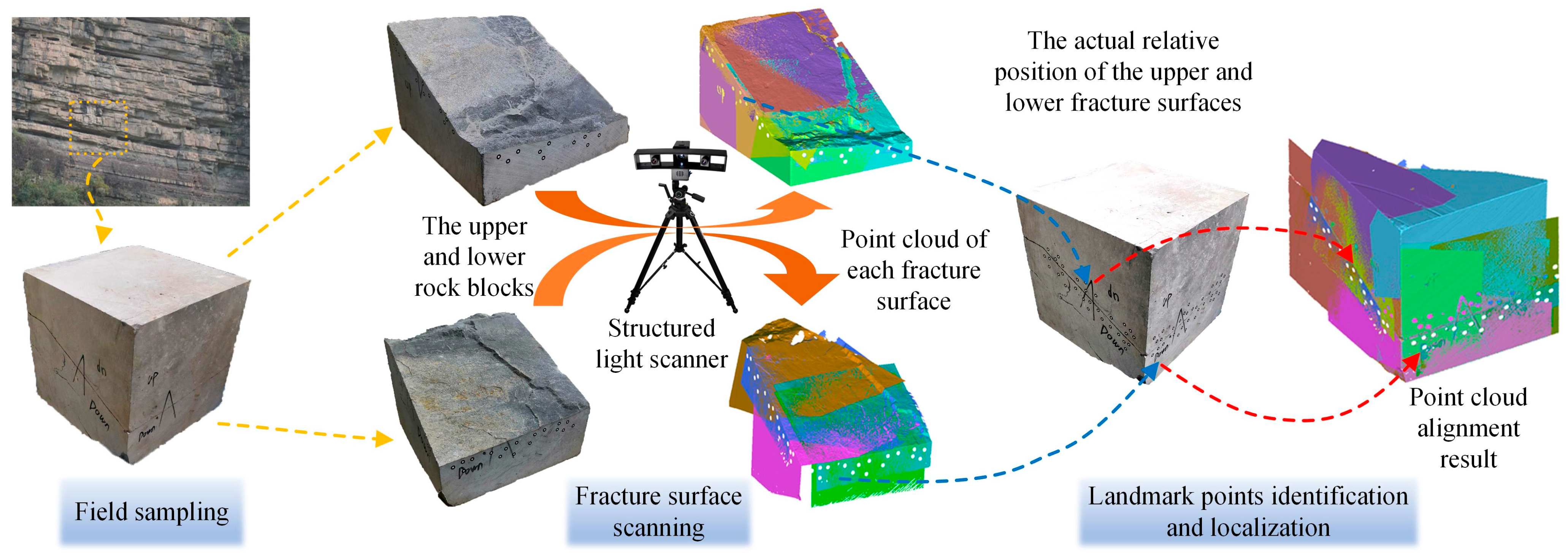
Figure 2, the spatial data of the fracture surface were obtained through the following steps:
- (1)
The upper rock block is placed upon the top of lower rock block, referring to the relative positions of the two rock blocks before the fracture was pried open.
- (2)
Along the edges of the fracture surfaces of the upper and lower rock block, an appropriate number of landmark points have been attached. We scanned the edge areas of the fracture surfaces with a structured light scanner. At this time, the computer software accompanying the scanner will number each landmark point and record its spatial coordinates, thereby obtaining the spatial relative positions of the upper and lower rock block and the two fractures inside them.
- (3)
After separating the upper and lower rock block, the fracture surfaces of each rock block will be scanned separately. Each scanning should include some landmark points and the software will identify the landmark points and align the newly obtained fracture surface data according to the relative positions determined in step 2.
The following is an introduction to the structured light scanner, its scanning principle, and the landmark point alignment technology.
The structured light scanner was employed in this study. As shown in
Figure 2, the structured light scanner mainly consists of a tripod and a sensor head containing a projector unit on center and two charge coupled device (CCD) cameras on each side. It is also working with a high-performance workstation to pilot the system and process scanning data.
To digitize the surface of rock fracture, the system projects a series of parallel blue-light fringe patterns onto the fracture surface. Images of these blue-light fringe patterns will become distorted due to the irregularity of the fracture surface. At the same time, the width of each fringe will be changed continuously to transform the continuous surfaces to discrete point cloud, which is called light coding. These series of images are automatically captured by the two CCD cameras and the software will compute precise 3D coordinates for each point based on the principle of triangulation. With the CCD camera resolution of 1280 × 1024 pixels, a point cloud of 1.3 million points can be obtained in a single measurement within 2 s.
Because only a local area of the fracture surface can be scanned at each time, multiple scanning results need to be combined to form a complete fracture surface. Artificial splicing of those surface data will introduce subjective influence, which may diverge the actual situation. Another key technique, landmark point location, was employed in this study to solve that problem. The theory of landmark point location has been discussed in our previous studies [
25,
26]. Even though the two sides of fracture are scanned separately, the usage of landmark point will make sure that the relative location of two sides of fracture surfaces in scanning data will be consistent with the specimen during the pre-step of scanning the landmark points. Therefore, the fracture flow space in scanning data will be same as the actual specimen. Because the scanned sample is not affected by crustal stress, there is still a certain difference between the scanned fracture space and the near-well fracture space, but this will not be discussed in this article. The scanning results of different parts of carbonate rock are shown in
Figure 2. Note that each part has been scanned multiple times and the scanning data have been marked with different colors.
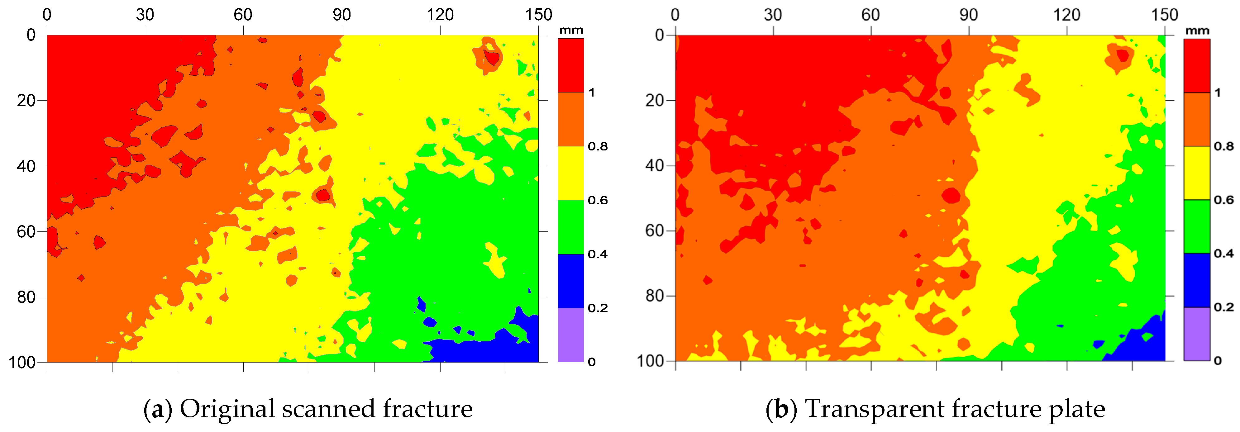
Taking into account the machining difficulty and pressure-bearing capacity of the fractured plate, a 150 × 100 mm rectangular area in the middle of the carbonate rock fracture was cut out in this research. The contour map of fracture aperture is shown in
Figure 3a. The average aperture is 0.76 mm, and the aperture range is 0.21 mm to 1.41 mm, which happens to be wedge-shaped. The fractal dimension of the fracture is 2.05 based on the box method [
27].
The method to obtain the fracture aperture is as follows:
- (1)
The fracture space is equivalent to a thin plate with an uneven surface that can be presented by a main plane. After spatial data of the fracture surface are obtained through optical scanning, we programmed a code to calculate the spatial position parameters of the main plane of the fracture.
- (2)
An orthogonal coordinate system was established on the main plane, with the Z-axis perpendicular to the main plane. The difference in the Z-axis coordinates of the two sides of the fracture was calculated, which is the fracture aperture and shown in
Figure 3a. Note that the relative displacement of the rock masses on both sides of the fracture will change the fracture aperture. And the fracture aperture in
Figure 3a is the status when scanning the landmark points of the fracture shown in
Figure 2.
- (3)
Errors are introduced during the modeling and processing of the transparent fracture plates. A developer was sprayed on the processed transparent fracture plates. After scanning the surface of transparent fracture plates and aligning the feature points (the bolt holes around the fracture plate showed in
Figure 4), the aperture of the flow space of visualization device was obtained, as shown in
Figure 3b.
Moreover, the conventional experimental apparatus for fracture plugging would apply confining pressure to the fracture module to maintain the seal of the device or simulate the variation in the fracture aperture in the formation by changing confining pressure.
In this paper, the visualization experimental apparatus is unable to apply confining pressure to the transparent fracture plate at present for real-time observation of the migration of the LCM in the fracture. Since the experimental fluid pressure is very low, only 0.06 MPa, the fracture aperture remains nearly unchanged during the experiment.
Concerning the fracture flow space, owing to the heterogeneity of rocks and the influence of multiple factors such as in situ stress, lithology, and geological processes, the specific morphology and flow space characteristics of wellbore fractures exhibit considerable variation. When fluid loss occurs through fractures and during the plugging operations, the fluid pressure within the wellbore is greater than that in the formation, causing the wellbore fractures to expand and assume a wedge shape. Specifically, the aperture at the fracture entrance near the wellbore is larger, while the aperture at the deeper part of the fracture is smaller, approaching the original fracture aperture before drilling. Hence, conventional indoor fracture plugging experimental apparatuses approximate the actual wellbore fracture flow space by placing two flat steel plates at a certain angle to form a long and narrow wedge-shaped space. We scanned the fracture surfaces of rocks and reconstructed the irregular fracture space in laboratory when there is no in situ stress applied to the two sides of the fracture. By manually selecting a local fracture area, an irregular fracture space with an overall wedge shape was obtained. Just as no two leaves are precisely identical, neither are fractures. Although the specific characteristics of the fracture space in the visualization experimental device of this paper may not be in complete accordance with those of actual wellbore fractures, they generally manifest the characteristics of irregular fracture surfaces and wedge-shaped flow channels. Therefore, the migration and bridge laws of LCM observed in the experiments hold guiding significance.
2.3. Machining Transparent Fracture Plates
In the study of rock mechanics, researchers often cast transparent resin on the fracture surface to make a transparent fracture plate and carry out fracture flow visualization experiments [
28,
29]. However, during the curing process of the transparent resin, it will first heat up and then cool down, resulting in a shrinkage of 5% to 10% of the fracture plate compared to actual rock fracture. At the same time, the edge of the fracture plate needs additional sealing treatment.
Since the fracture morphology has been fully digitalized, in this study, the fracture surfaces have been directly carved on the transparent PMMA plates to make the transparent fracture plates. In addition to the transparent resin plates on two sides, the transparent fracture plate also includes an aluminum frame in the middle, which contains an O-ring seal between them and is fixed by many bolts, as shown in
Figure 4.
After machining the transparent fracture plate, the fracture plate surface has been sprayed by the developer and scanned to obtain the fracture aperture of the transparent fracture plate as shown in
Figure 3b, which demonstrate that the aperture distribution of the transparent fracture plate is almost consistent with the scanned specimen.
2.4. Experimental Device and Procedure
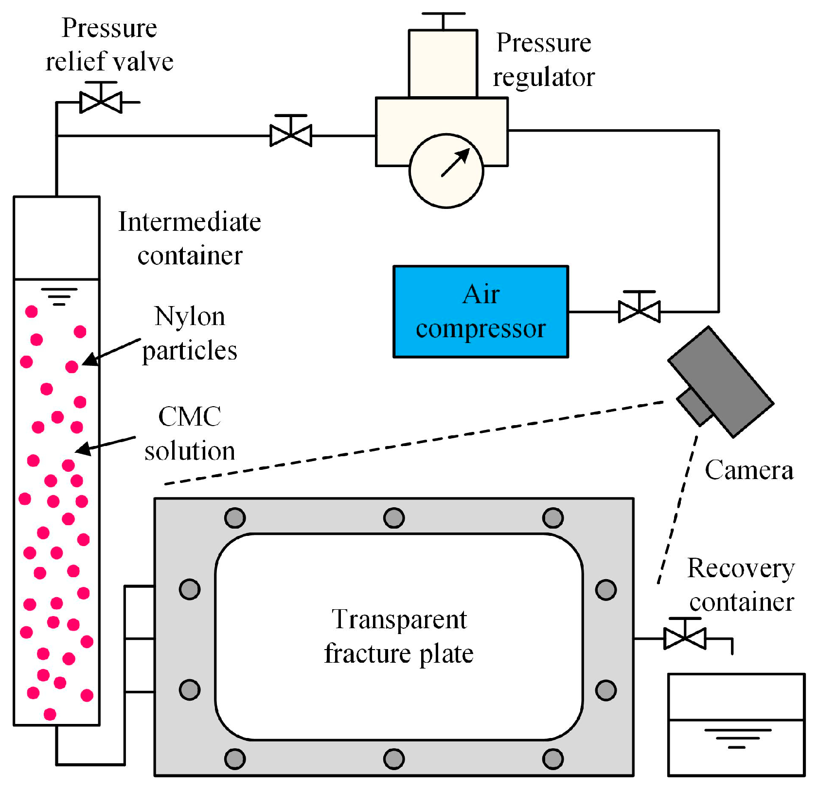
As shown in
Figure 5, besides the transparent fracture plate, the fracture plugging visualization experimental device also includes an air compressor, intermediate container, pressure regulating valve, recovery container, camera and other components.
In order to achieve visualization observation, this study used transparent solution containing 1% sodium carboxymethyl cellulose (CMC) and 99% pure water to simulate the drilling fluid with a viscosity of 70 mPa·s. The CMC solution possesses rheological properties and viscosity similar to those of drilling fluids, can effectively suspend the plugging particles, and is transparent to ensure satisfactory observation. At the same time, purple cylindrical nylon particles, as shown in
Figure 6a, were adopted as LCM instead of the commonly used calcium carbonate particles to carry out experiments.
In wellbore fracture plugging operations, walnut shells, calcium carbonate particles, etc., are frequently employed as LCM due to their low cost and extensive availability. These are mixed with drilling fluid and injected into the fractures around the wellbore. Through bridging and accumulation within the fractures, a dense plugging zone is gradually established, ultimately plugging the fractures and preventing fluid loss. This is the most commonly adopted fracture plugging treatment, known as bridging plugging.
After plugging the fractures, these particles are heated by the formation rocks, and their temperature gradually rises to several tens or even hundreds of degrees Celsius, eventually reaching the formation temperature. Subsequently, a reduction in mechanical strength occurs, leading to plugging failure, namely the aging of plugging performance. Therefore, the drilling industry is currently developing high-temperature-resistant LCM. The LCM utilized in the experiments of this paper is a kind of high-temperature-resistant nylon particle capable of maintaining a certain mechanical strength at high geothermal temperatures. The density of nylon particle is 1.14 g/cm3, and they can be processed into multiple sizes such as 0.8 mm, 0.6 mm, 0.4 mm, and 0.2 mm. In this paper, only 0.8 mm and 0.4 mm nylon particles were used.
It is worth mentioning that the size of nylon particles marked in
Figure 6a is both its length and diameter, which are the same. Since nylon particles are cylindrical rather than standard spherical, they may rotate and bridge under different postures at various fracture apertures, including 1 to
times the particles’ size, as shown in
Figure 6b,c.
In the experiment, the CMC solution is first injected into the fracture plate to squeeze out the air. Subsequently, the CMC solution mixed with purple nylon particles of a specific size and concentration is placed into the intermediate container, and then the slurry enters the fracture plate under a specific pressure by adjusting the pressure-regulating valve. Fluid flowing out of the fracture plate is collected and the whole experiment is recorded by a camera.
Regarding the injection pressure of the experimental fluid, or more precisely, the fluid pressure gradient, it is one of the key factors influencing the fluid flow rate and directly affects the migration speed and pattern of the LCM in the fracture. In conventional fracture plugging experiments, a pressure differential of 5 to 20 MPa may be applied at the entrance and exit of the fracture, with the sole aim of evaluating the ultimate pressure-bearing capacity of the LCM. However, this study concentrates on the early migration and bridging process of the LCM in the fractures rather than their ultimate pressure-bearing capacity. Consequently, such a high-pressure differential is not a requisite. In actuality, before the wellbore fractures are completely plugged, there exists a pressure gradient and fluid flow along the entire length of the fracture. When drilling fluid loss takes place, the bottom hole pressure may be 1 to 10 MPa higher than the formation fluid pressure, and the length of the wellbore fractures may exceed 10 m. Thus, the average pressure gradient within the wellbore fractures is approximately 0.1 to 1 MPa/m. In the experiments of this paper, the pressure differential at the entrance and exit of the fracture is 0.06 MPa, and the fracture length is 0.15 m, resulting in a pressure gradient of 0.4 MPa/m, which is consistent with the actual situation of the drilling site. Additionally, experiments were previously conducted under a pressure differential of 0.2 MPa, but it was discovered that the fluid flow rate was excessively fast, and the fracture was completely plugged within less than 10 s, which is inconsistent with actual engineering experience and is not conducive to the analysis of the experimental results. Moreover, an overly high pressure could lead to deformation or even rupture of the transparent fracture plates. To sum up, we eventually chose 0.06 MPa as the injection pressure of the experimental fluid.
Overall, the summary of the experimental parameters is presented in
Table 1.
5. Conclusions
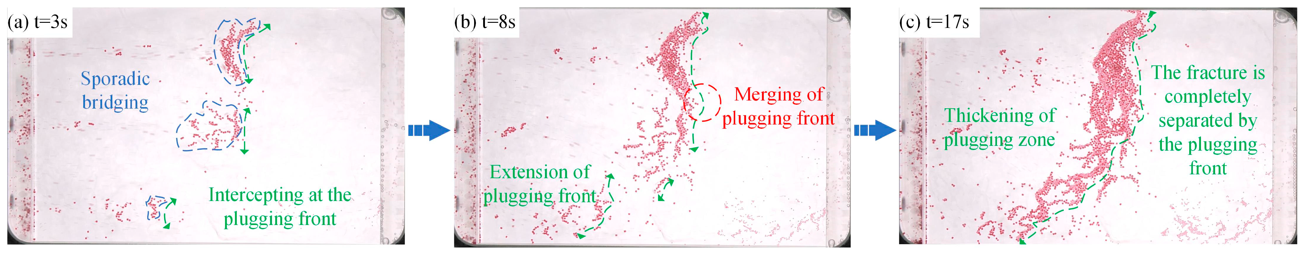
According to the visualization experiment results, the process of fracture plugging includes the sporadic bridging, plugging zone extension and merging, thickening of the plugging zone and complete plugging of fractures.
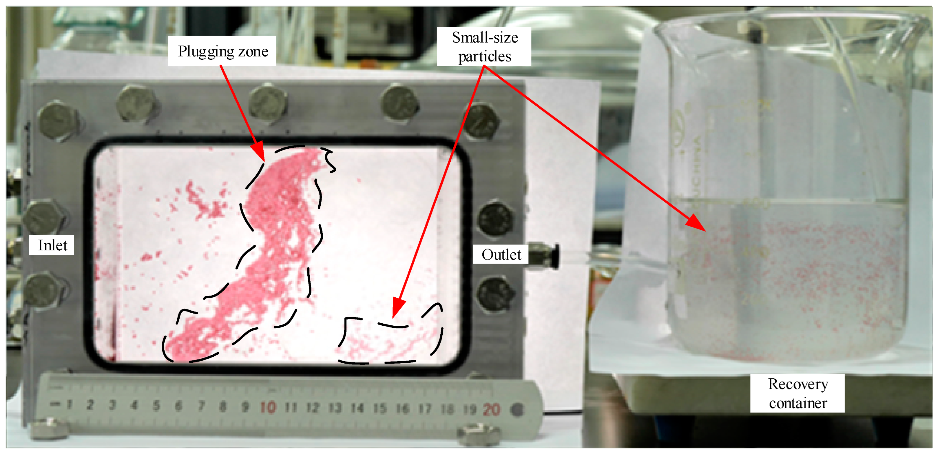
The LCM injection method has a significant influence on the LCM migration process in the fracture and the final fracture plugging effect. Through the visualization experiment of fracture plugging, it is discovered that under the traditional simultaneous injection method, LCM of various sizes concurrently enters the fracture space. Before the large-sized LCM particles bridge to form a complete plugging zone within the fracture, a considerable number of small-sized LCM particles enter the deep part of the fracture, which will result in a certain amount of LCM waste, reduced sealing efficiency, and reservoir damage issues.
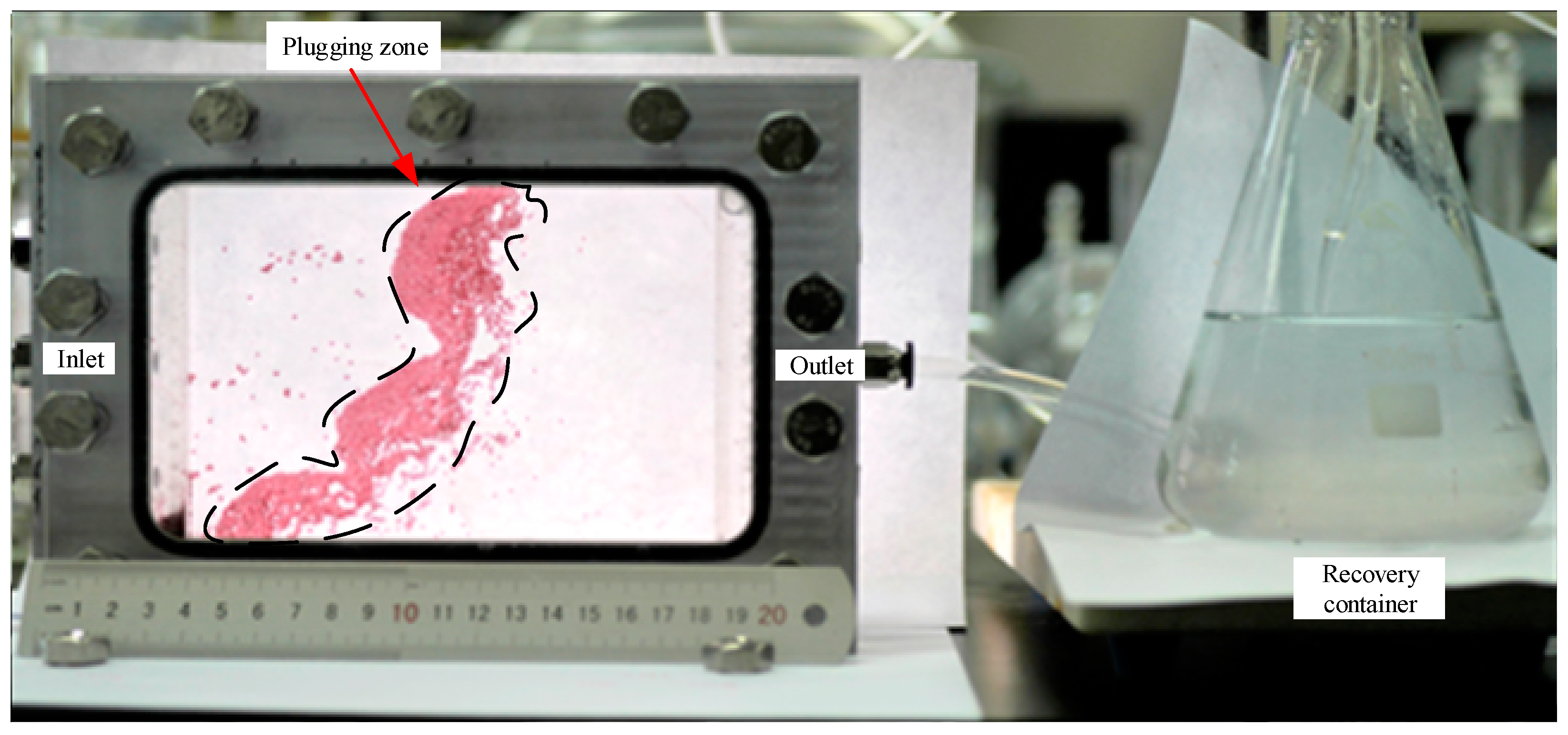
However, upon adopting the graded multiple injection method, the large-sized LCM particles injected into the fracture first, followed by almost all of them, bridged within the fracture, rapidly forming a complete plugging zone, enabling the subsequent small-sized LCM particles to be fully employed to expand the plugging area and enhancing the plugging effect, thereby avoiding LCM waste, improving the plugging efficiency, and precluding reservoir damage problems.
Consequently, the graded multiple injection method, without altering the overall usage amount of LCM, enhances the fracture plugging effect while averting reservoir damage problems, possessing promotion value in engineering.
The visualized experimental method for fracture plugging proposed in this paper can also benefit other research areas such as proppant placement and solute transport in rock fractures.


