1. Introduction
Nitrogen-rich carbon nitride g-C
3N
5 recently received much attention as a newly emerged photocatalyst. In comparison to g-C
3N
4, g-C
3N
5 exhibits a narrower band gap energy and a higher potential of having a conductive band (CB) due to the nitrogen-rich matrix. In particular, the presence of a triazole unit with N–N coupling within the g-C
3N
5 framework enhances its ability to absorb light, extending its absorption range into the visible spectrum—substantially broader than that of g-C
3N
4 [
1,
2]. As a result, g-C
3N
5 has been increasingly considered as a viable alternative to g-C
3N
4 in various applications, including photocatalytic degradation of organic compounds [
3] and H
2 production [
4]. However, similar to single-component photocatalysts, sluggish charge transfer may hinder its broader application. The synthesis of composites containing g-C
3N
5 and metallic/bimetallic nanoparticles could provide a versatile approach to enhancing the H
2 evolution of g-C
3N
5 [
5]. Under irradiation, electrons in the valence band (VB) of g-C
3N
5 undergo excitation, moving to the CB of g-C
3N
5 and leaving behind a hole in the VB of g-C
3N
5. The efficient electron/hole separation is preferably achieved when metallic/bimetallic nanoparticles are anchored on a g-C
3N
5 server as electron acceptors. Electron acceptors play a crucial role in capturing electrons from the CB of g-C
3N
5, thereby initiating the hydrogen evolution reaction on the conduction band of g-C
3N
5 layers. During this process, protons (H
+) react with captured electrons to produce H
2, attributed to the more positive CB value of g-C
3N
5 in comparison to the standard reduction potential (H
+/H
2).
The distribution and loading of metallic/bimetallic nanoparticles on the g-C
3N
5 layers has been achieved through various methods, such as wet-chemical reduction, photochemical reduction, and high-temperature reduction under an inert atmosphere. Among these, the wet-chemical reduction method using organic capping ligands enables the controllable size and uniform distribution of metallic and bimetallic nanoparticles on g-C
3N
5 layers, which is expected to significantly enhance photocatalytic activity compared to other synthesis methods [
6,
7].
In our approach, we employ wet-chemical reduction using ethylene glycol (EG) acting as both a capping and reduction agent for loading Pd° nanoparticles (NPs) on the g-C3N5 matrix, ensuring a better metal–support interaction. For comparison, we also synthesized Pd/g-C3N5 via the photoreduction method. In addition, the Pd/g-C3N5 composite, prepared according to these methods and employing PdCl2 as the Pd source, may be more cost-effective than using Pt. This approach avoids the introduction of additional impurities, allows for easy control of the reaction conditions, maintains a low production cost, and facilitates straightforward large-scale production.
2. Materials and Methods
2.1. Materials
All the chemicals were used without further purification. 3-amino-1,2,4-triazole (C2H4N4, 99%), palladium (II) chloride (PdCl2, 99%), and Nafion (5 wt.% in lower aliphatic alcohols and water, contains 45% water) were purchased from Sigma-Aldrich (St. Louis, MO, USA). Ethylene glycol (EG, C2H6O2, 99%), methanol (CH4O, 99%), ethanol (C2H6O, 99%), potassium ferricyanide (K3Fe(CN)6, 99%), sodium sulfate (Na2SO4, 99%), potassium cyanide (KCN, 98%), and triethanolamine (TEOA, C6H15NO3, 99%) were purchased from Junsei (Tolyo, Japan).
2.2. Synthesis of g-C3N5 Photocatalyst by a Thermal Condensation Method
The g-C
3N
5 photocatalyst was fabricated using a thermal condensation method with 3-amino-1,2,4-triazole as the starting material [
8]. Specifically, 3 g of 3-amino-1,2,4-triazole powder was thoroughly ground into an aluminum crucible with a lid. The crucible was then heated to 550 °C in a muffle furnace for 4 h under ambient conditions, with a heating rate of 5 °C min
−1. The as-obtained sample was ground into a fine powder, and after dispersing deionized water, it was stirred continuously for 2 h. The final g-C
3N
5 sample was collected by centrifuge and dried under vacuum at 60 °C overnight.
2.3. Synthesis of Pd/g-C3N5 Composite
The Pd/g-C3N5 heterojunction was synthesized by the wet-chemical method, referred to as Pd/g-C3N5-EG. In a typical procedure, 300 mg of g-C3N5 was dissolved in 100 mL of EG, sonicated for 30 min, and then placed in the ice-water bath with continuous stirring. After stirring for 30 min, 0.6 mL of PdCl2 solution (2.5 mg Pd/mL) was added dropwise into the g-C3N5-EG suspension, followed by additional stirring for 2 h. The Pd content was set at 0.5 wt.%. Then, the solution was transferred into a flask and heated in an oil bath at 140 °C for 2 h. After cooling to room temperature, the Pd/g-C3N5-EG solid was collected by centrifugation, washed with deionized water and ethanol at least three times, and finally dried under vacuum overnight at 60 °C.
For comparison, the Pd/g-C3N5 composite was also synthesized via a photoreduction method, denoted as Pd/g-C3N5-PR. Firstly, 300 mg of g-C3N5 was suspended, dispersed in 100 mL of 20% (v/v) methanol solution, and sonicated for 30 min to form a suspension. Then, the mixture was transferred into the double-layer beaker, and 0.6 mL of PdCl2 solution (2.5 mg mL−1) was added dropwise to the suspension. The Pd content was set at 0.5 wt.%. The suspension was stirred for the next 2 h before it was illuminated under a 300 W Xenon lamp with a 420 nm filter cutoff for 2 h. The Pd/g-C3N5-PR product was collected by centrifuge, rinsed with ethanol and DI water several times, and dried at 60 °C overnight.
2.4. Characterization
The crystal structure of photocatalysts was analyzed using X-ray diffraction (XRD) spectra from an X’Pert3-Powder X-Ray Diffractometer (PANalytical, Malvern, UK) with a 2θ range of 10–80°. The morphologies and structures of as-prepared catalysts were investigated by field emission transmission electron microscopy (FE-TEM) and energy-dispersive spectroscopy (EDS, Tokyo, Japan) analysis using JEM-F200 (JEOL, Tokyo, Japan). UV-Vis diffuse reflection spectra (UV-Vis DRS) of g-C3N5 and Pd/g-C3N5 photocatalysts were recorded using Shimadzu UV-Vis spectroscopy (UV-2600, Tokyo, Japan). The photoluminescence (PL) spectra of the as-prepared samples were obtained at room temperature using a photofluorescence luminescence spectrophotometer system (Fluorolog-QM, HORIBA, Kyoto, Japan), with the excitation wavelength set at 360 nm.
2.5. Electrochemical Analysis
The electrochemical measurements were performed using a ZIVELAB single-channel electrochemical workstation (Seoul, Republic of Korea). The Ag/AgCl electrode, Pt wire, and ITO substance with the sample were used as the reference, counter, and working electrodes, respectively, for the three-electrode system. The working electrodes were prepared as follows: the as-prepared photocatalyst (10 mg) was mixed with a solution containing 20 μL Nafion and 1 mL isopropanol solution (isopropanol/H2O = 1/3 v/v). Then, the mixture was sonicated for 60 min before being coated on an ITO glass (5 mm × 15 mm). Electrochemical impedance spectroscopy (EIS) Nyquist was performed with the frequency set in the range of 0.1 Hz to 1 MHz and an amplitude of 5 mV. The electrolyte solution was a mixture of K3Fe(CN)6 and KCN at concentrations of 2 mM and 1 M, respectively. The Mott–Schottky test was performed at a frequency of 1 kHz, and the amplitude was in the range of −1 V and 1 V, using 0.5 M of Na2SO4 (pH = 6.97) as the electrolyte. Electrochemical measurements were performed in the dark. The data were analyzed using ZMAN 2.5 software.
2.6. Catalytic Activity Tests
The photocatalytic activity of the as-synthesized samples was evaluated by measuring their efficiency of H
2 production. In brief, 50 mg of the photocatalyst was evenly dispersed in 10 mL of TEOA and 90 mL of DI water through sonication. This mixture was then transferred to a 250 mL flask, which was sealed with a rubber stopper. The gas was removed by vacuuming for 15 min, followed by N
2 gas purging for an additional 15 min. After that, the flask was illuminated with a 300 W Xenon lamp with the 420 nm cutoff filter for 3 h to facilitate H
2 production. The generated H
2 gas was determined using an HP gas chromatograph (GC5890 series II, Santa Clara, CA, USA) equipped with a thermal conductivity detector (TCD), using 5 Å molecular sieve columns and Ar as the carrier gas. The calibration of the TCD signal for H
2 using various dilutions of H
2 in N
2 is shown in
Figure 1. To confirm the stability of the photocatalyst, a recycling test was conducted. The catalyst was washed with ethanol and DI water after each cycle, and their photocatalytic performance was re-evaluated.
3. Results
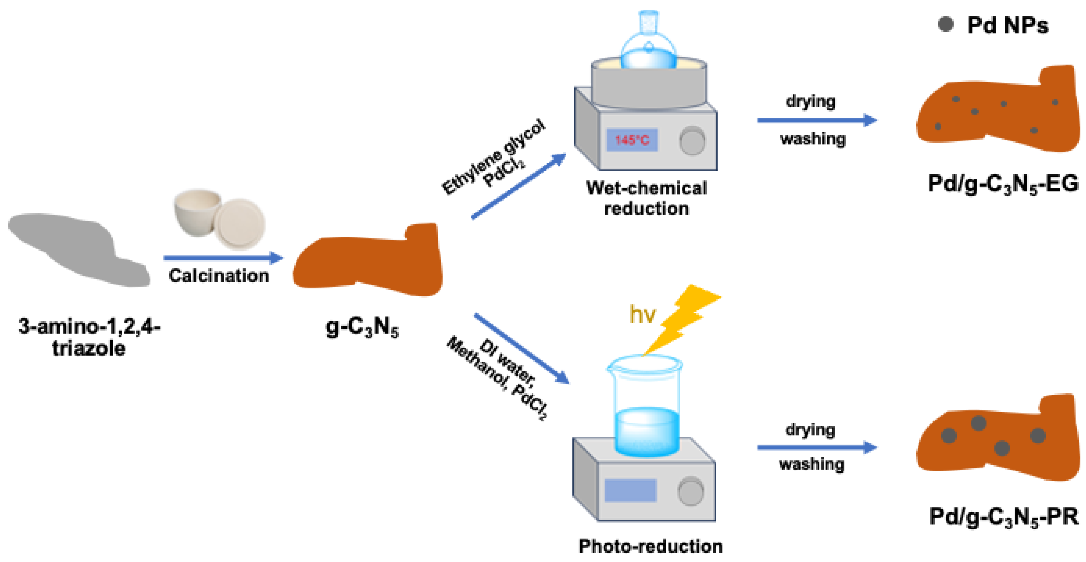
The Pd/g-C
3N
5 composites were prepared following the procedure outlined in
Figure 2. Initially, g-C
3N
5 was synthesized by heating 3-amino-1,2,4-triazole at 550 °C under an ambient atmosphere. Subsequently, the wet-chemical reduction and photoreduction methods were applied to distribute metallic Pd nanoparticles onto the g-C
3N
5 layer. In both routers, a PdCl
2 solution served as the precursor solution to form the metallic Pd nanoparticles. In the wet-chemical reduction, the Pd
2+ ion in the solution was reduced to Pd by EG. In the photoreduction method, the Pd
2+ ion in the solution was reduced to Pd by the electrons from the conduction band of g-C
3N
5 during the photocatalytic reaction. In addition, the presence of EG as an organic capping ligand facilitates precise control over the shape and size of Pd nanoparticles, which is expected to enhance their photocatalytic activity.
The XRD patterns of all catalysts are consistent with those reported in previous studies on g-C
3N
5 (
Figure 3A) [
1,
9]. The introduction of metallic Pd does not appear to significantly alter the crystalline structure of g-C
3N
5. Additionally, the distinct peaks of the Pd° NPs were not observed, due to the tiny atomic diameter of metallic Pd° nanoparticles and their relatively low concentration in the composite. Pd° and Pd
2+ species were detected in both Pd/g-C
3N
5-EG and Pd/g-C
3N
5-PR samples (
Figure 3B). Notably, the Pd° content was highest in Pd/g-C
3N
5-EG, indicating that the wet-chemical reduction method employing EG as a reducing agent was particularly effective in promoting Pd
2+ reduction. In addition, compared to g-C
3N
5-PR (
Figure 3(C1,C2)), Pd/g-C
3N
5-EG (
Figure 3(D1,D2)) shows a finely dispersed metallic Pd homogeneously distributed on g-C
3N
5 layers, underscoring the superiority of the wet-chemical reduction method for synthesizing metallic Pd over the photoreduction method. This outcome is anticipated to result in enhanced photoelectrochemical properties.
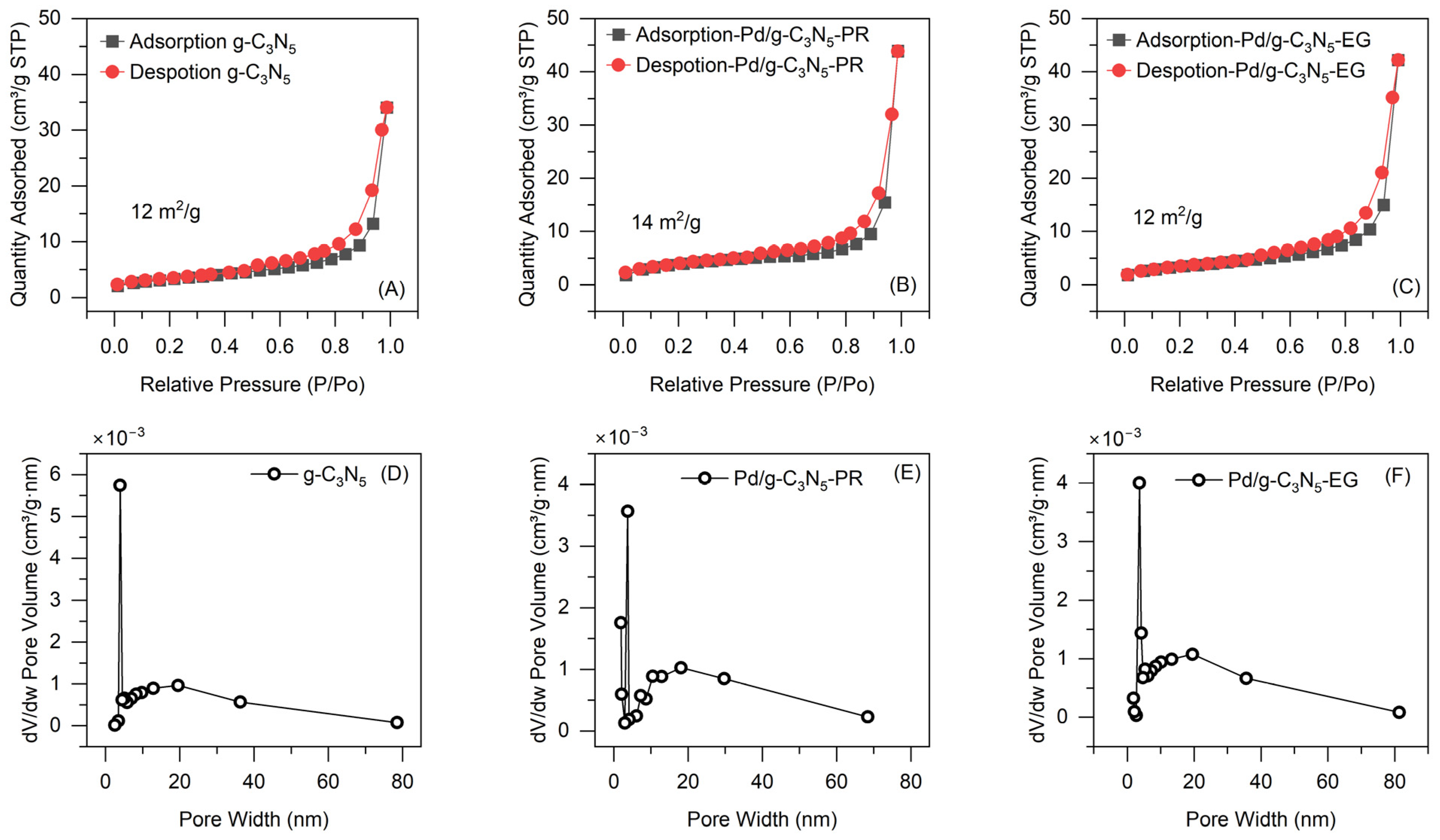
Figure 4 illustrates the N
2 adsorption–desorption isotherms and pore width distribution for catalysts. The g-C
3N
5 possesses a BET surface area of 12 m
2 g
−1 with a pore size of 4 to 6 nm. The introduction of Pd° NPs in g-C
3N
5 did not significantly change the textural properties of the g-C
3N
5.
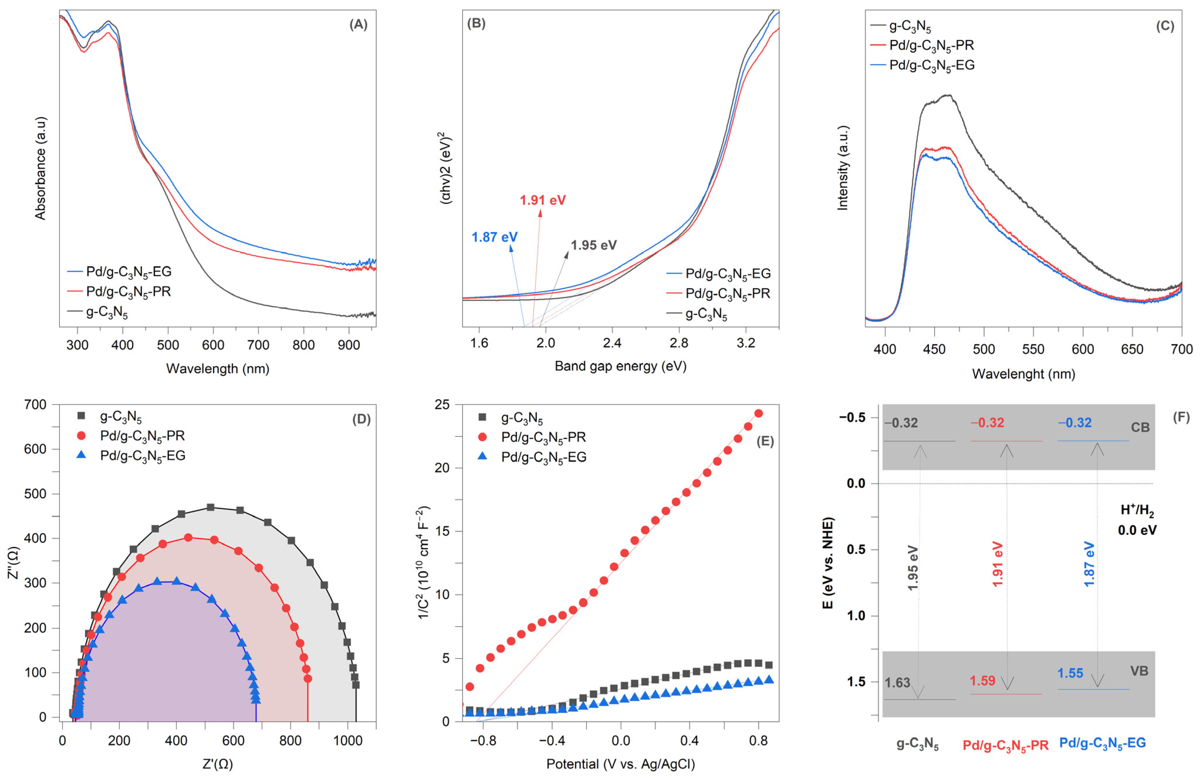
Figure 5A depicts the ultraviolet–visible diffuse reflectance spectra of pure and Pd°-decorated g-C
3N
5 samples. The g-C
3N
5 exhibits robust absorption across the solar spectrum, with a band edge wavelength of 650 nm, which is attributed to its narrow band gap [
1,
5,
9]. The absorption spectra of g Pd/g-C
3N
5 composites appear to undergo no significant change upon the introduction of metallic Pd. The band gap (E
g) values for pure and Pd°-decorated g-C
3N
5 samples were determined from the plots of (αhν)
1/2 against photon energy (
Figure 5B). The estimated E
g values were 1.95 eV for g-C
3N
5, 1.87 eV for Pd/g-C
3N
5-EG, and 1.91 eV for Pd/g-C
3N
5-PR.
Figure 5C illustrates the photoluminescence of g-C
3N
5 and Pd/g-C
3N
5 composites. The g-C
3N
5 samples exhibit an emission peak in the range of 400–600 nm, which is attributed to the band-to-band photoluminescence [
1]. The Pd/g-C
3N
5 composites show a lower photoluminescence intensity compared to g-C
3N
5, indicating that the recombination rate has been effectively suppressed due to the introduction of Pd° NPs.
In the Nyquist plot, a higher curvature corresponds to lower charge transfer resistance. The curvature of the Nyquist curve follows the order of Pd/g-C
3N
5-EG > Pd/g-C
3N
5-PR > g-C
3N
5, indicating that Pd/g-C
3N
5-EG has the smallest impedance (
Figure 5D). This finding verifies the improved charge transfer mechanism at the interface between Pd° NPs and g-C
3N
5, facilitating the movement of charge carriers. The excellent electron transport efficiency from g-C
3N
5 to Pd° NPs enhances the transmission and separation of charge carriers, thereby improving photocatalytic hydrogen production performance. Moreover, the Pd° NP-decorated g-C
3N
5 layer synthesized via wet-chemical reduction demonstrated a more effective metal–support interaction compared to the photoreduction method, leading to an expected higher hydrogen production yield. As discussed in the introduction section, the wet-chemical reduction method, employing organic capping ligands, facilitates the precise control of nanoparticle size and ensures a uniform distribution of Pd° NPs on g-C
3N
5 layers. This approach is anticipated to significantly affect the interface properties between Pd° NPs and g-C
3N
5 compared to the photoreduction method.
The conduction band level (E
CB) was determined using Mott–Schottky plots (
Figure 5E). The E
CB values for all samples were determined to be −0.32 eV (vs. NHE), as previously demonstrated [
10]. The valence band position (E
VB) was then calculated using the following equation: Eg = E
VB − E
CB. Based on this, the E
VB values are 1.55 eV for Pd/g-C
3N
5-EG, 1.59 eV for Pd/g-C
3N
5-PR, and 1.63 eV for g-C
3N
5. The energy band diagrams for pure and Pd°-decorated g-C
3N
5 samples are illustrated in
Figure 5F.
Figure 6A shows the photocatalytic H
2 evolution rates over g-C
3N
5 and Pd/g-C
3N
5 composites. The average hydrogen evolution rate for Pd/g-C
3N
5-EG is approximately 891.304 µmol g
−1 h
−1 under visible light irradiation, representing a 34.5-fold increase compared to the pristine g-C
3N
5 at 23.753 µmol g
−1 h
−1 and a 7.8-fold increase compared to Pd/g-C
3N
5-PR at 113.418 µmol g
−1 h
−1.
Figure 6B shows photocatalytic H
2 evolution rates over Pd/g-C
3N
5-EG composites after five reaction cycles. The hydrogen evolution performances of Pd/g-C
3N
5-EG remain stable across the testing cycles, highlighting the excellent stability of the catalysts.
The schematic band structure diagram of g-C
3N
5 and Pd/g-C
3N
5 composites (
Figure 5F) reveals minimal differences in the CB and VB values between g-C
3N
5 and Pd/g-C
3N
5, suggesting the establishment of the heterojunction between Pd° NPs and the g-C
3N
5 layer. In this configuration, Pd° NPs play a role as electron traps, accumulating electrons from g-C
3N
5 due to the smaller work function of g-C
3N
5 (5.2 eV vs. vacuum [
11]) compared to Pd° (5.6 eV vs. vacuum [
12]). The establishment of a heterojunction effectively prevents the reverse migration of electrons trapped by Pd° NPs, thus promoting enhanced electron-transfer pathways. In addition, the Pd nanoparticle-decorated g-C
3N
5 layer, obtained through wet-chemical reduction, exhibited an excellent hydrogen production yield compared to the Pd° nanoparticle-decorated g-C
3N
5 layer obtained by photoreduction. The smaller size and uniform distribution of Pd° NPs in the wet-chemical reduction process can enhance the effective metal–support interaction with g-C
3N
5 layers. As a result, the favorable electronic transmission properties of uniformly distributed Pd° NPs in the Pd/g-C
3N
5-EG enable them to act as electron acceptors, effectively capturing photogenerated electrons and accelerating the separation of electron–hole pairs, thereby enhancing hydrogen production yield.
Because the energy level of the photogenerated electrons on the CB of g-C
3N
5 (−0.32 eV) is higher than the H
+/H
2 redox level (0.0 eV), these electrons produced by g-C
3N
5 under visible light irradiation can effectively reduce H
+ to generate H
2. However, the presence of O
2 and photogenerated holes can hinder the H
2 evolution process. To mitigate their effects, O
2 was purged from the reactor using N
2 gas and the holes were trapped by triethanolamine (TEOA). In this inert atmosphere, the H
2 evolution process can be described by Equations (1)–(3).
However, the rapid recombination of photogenerated carriers may limit the photocatalytic activity of g-C3N5. To overcome this, Pd° NPs, acting as electron accepters, can capture the photogenerated electrons from the CB of g-C3N5. Then, these electrons migrate to the Pd° NP surface, where they participate in the reduction of H+ to generate H2.


