Article

Implementation of an Improved 100 CMM Regenerative Thermal Oxidizer to Reduce VOCs Gas

1
Emsolution Co., Ltd., Suwon 16571, Republic of Korea
2
Kaywon Design Innovation Sharing Center, Kaywon University of Art & Design, Uiwang 16038, Republic of Korea
3
Department of Electronic Engineering, Semyung University, Jecheon 27136, Republic of Korea
*
Author to whom correspondence should be addressed.
Processes 2024, 12(12), 2814; https://doi.org/10.3390/pr12122814
Submission received: 21 September 2024 / Revised: 30 November 2024 / Accepted: 4 December 2024 / Published: 9 December 2024

Abstract

:
In this paper, an improved 100 CMM regenerative thermal oxidizer (RTO) is implemented for low-emission combustion. The existing RTO system is a cylindrical drum structure that cyclically introduces and discharges VOC gas into and from the rotating disk, and which achieves excellent energy efficiency with a heat recovery rate of more than 95%. However, the drive shaft designed under the RTO combustion chamber increases wear around the rotating shaft due to the load of the combustion chamber and there is a problem that the untreated gas is simultaneously released through the outlet due to the channeling phenomenon of the combustion chamber and the drive shaft. In addition, the combustion chamber, used at a high temperature of 800 °C, may cause serious problems such as rotation stop or explosion due to pollutants, dust accumulation, and thermal expansion in the chamber. Particularly when treating VOCs harmful gasses, RTO performance may be degraded due to the burner’s non-uniform temperature control and unstable combustion function. To solve this problem, first, the design of the combustion chamber rotating plate driving device is improved. Second, when treating high concentration VOC gas, the design of combustion chamber considers a temperature increase of up to 920 °C or more. For this, the diameter of the gas burner is 125 mm and the outlet dimension is set to 650 mm × 650 mm to effectively discharge high-temperature waste heat. Third, the heat storage material in the combustion chamber is composed of a ceramic block with a thickness of 250 mm, and the outer diameter and height of the combustion chamber are set to, 2530 mm and 1875 mm, respectively, to optimize gas residence time and heat insulation thickness. Fourth, we supplement safe operation by applying the trip control algorithm of the programmable logic controller (PLC) panel for failure prediction of RTO and the Edge-IoT-based intelligent algorithm for this. Finally, we evaluate the economic performance of 100 CMM RTO by conducting empirical experiments to analyze changes in VOCs removal efficiency, nitrogen oxide emission concentration, and total hydrocarbon (THC) concentration through 10 CMM design and implementation.

1. Introduction

Globally, efforts are being made to reduce greenhouse gasses and achieve zero carbon emissions in response to global warming. The goal is to keep the increase in global average temperature due to climate change within 2 °C above pre-industrial levels, with a long-term target of limiting it to 1.5 °C [1]. Industrial emissions of volatile organic compounds (VOCs) must be urgently addressed due to their toxicity and carcinogenicity to humans. Developing efficient and eco-friendly reforming technologies for VOCs is essential but remains a significant challenge [2].
VOCs emitted from chemical plants, metal painting facilities, and petroleum plants contribute to air pollution and pose serious health risks, including toxicity and carcinogenicity. Thus, the development of eco-friendly technologies for their treatment is a critical task [3,4]. Meanwhile, technologies for carbon capture, utilization, and storage (CCUS) have been proposed to address CO₂ emissions from petrochemical and coal-fired power plants [5].
Typically, maintenance activities such as pipe replacement, facility cleaning, residual gas removal, and process improvement are conducted every 4 to 5 years. However, most facilities are outdated, operate with low efficiency, and emit substantial amounts of pollutants, thereby severely impacting the environment. To develop innovative solutions and improve fuel combustion efficiency, the previous literature [6] has suggested methods to enhance fuel conversion efficiency by heating the substrate during the combustion process and recovering heat from the combustion gas through cooling and steam condensation.
To analyze the reduction in nitrogen oxide (NOx) emissions, the design and system were studied in terms of the effects of temperature, oxygen concentration, and secondary combustion air volume in a single burner combustion system [7]. Park, H.M., Yoon, D.H. et al. [8] published a study on the development of porous plate scrubbers and simulations of isopropyl alcohol (IPA) treatment efficiency for improved dust collection and deodorization.
One of the environmentally friendly methods for emission reduction involves low-emission waste energy utilization through the combustion of liquid fuel mixed with superheated steam and carbon dioxide in the combustion zone [9]. This approach benefits from the reduction and recycling of CO₂ by utilizing it alongside or in place of steam.
Until now, VOC removal and reduction technologies have included anti-diffusion methods, physical methods, chemical methods, and biological methods [10]. Among chemical methods, combustion has evolved into various approaches, such as direct combustion (thermal oxidation), catalytic oxidation, and regenerative thermal oxidation, which oxidize and decompose VOCs at high temperatures. Despite these advancements, energy costs remain high due to low heat recovery rates. To address this, technologies capable of effectively treating more than 95% of VOCs have been developed, such as heat storage combustion systems and heat storage catalytic combustion systems [11].
Jeon, D.H. and Jung, S.W. [12] studied pretreatment methods for irregular process emissions to enable high-efficiency combustion treatment of VOCs. Yoon, D.-H. and Jeon, D.-H. et al. [13] subsequently proposed a method to increase fuel conversion efficiency by heating the substrate during the combustion process and recovering heat from combustion gasses through cooling and vapor condensation. Meanwhile, the evolution of heat storage combustion oxidizing agents for VOC treatment has progressed from the first-generation damper method to the third-generation rotary valve method.
To reduce air pollution at VOC production sites, 100 CMM and 10 CMM regenerative thermal oxidizer (RTO) devices were designed. Heat transfer system specifications and emission concentration measurement techniques were proposed through studies of phase transformations for high-temperature waste heat recovery [14]. Figure 1 shows the evolution of the heat storage combustion oxidation device [15,16].
In this paper, we implement an improved combustion 100 CMM and 10 CMM heat storage oxidizer (RTO) capable of treating more than 95% of the volatile organic compounds (VOCs) gas generation sites. It is implemented to compensate for the amount of untreated gas discharged due to abrasion and channeling as a result of the driving force of the disk rotating plate in the combustion chamber, which is pointed out as a disadvantage of the existing RTO, and the accuracy of the design implementation is guaranteed through flowability analysis.
In addition, when used for a long time, there is a problem that rotation stops or explodes due to the discharge of pollutants due to dust and thermal expansion as a result of high temperature (800 °C). To improve this, the improved rotating plate drive device is redesigned while maintaining normal operation of the RTO combustion chamber. Considering that the combustion chamber temperature rises to 920 °C when treating high concentration VOC gas, the gas burner is designed to have a diameter of 125 mm and an outlet of 650 mm × 650 mm to release high-temperature waste heat. At this time, the combustion chamber heat storage material is designed such that the thickness of the ceramic block, the outer diameter, and the height of the combustion chamber are 250 mm, φ 2530 mm, and 1875 mm, respectively, in consideration of the residence time of the treatment gas and the thickness of the insulation. We present intelligent PLC implementation and data monitoring through Edge-IoT, which plays a major role in RTO-driven operations, which present a VOCs removal rate of more than 95% and energy savings of more than 20%.

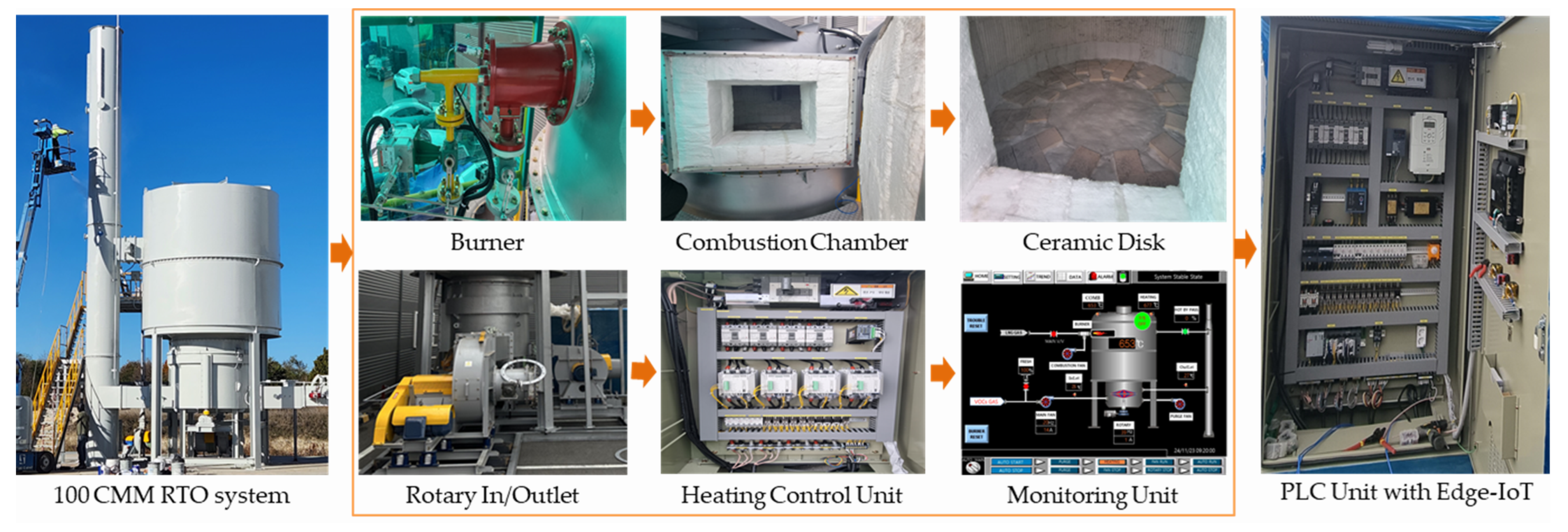
2. Implementation of Improved 100 CMM RTO

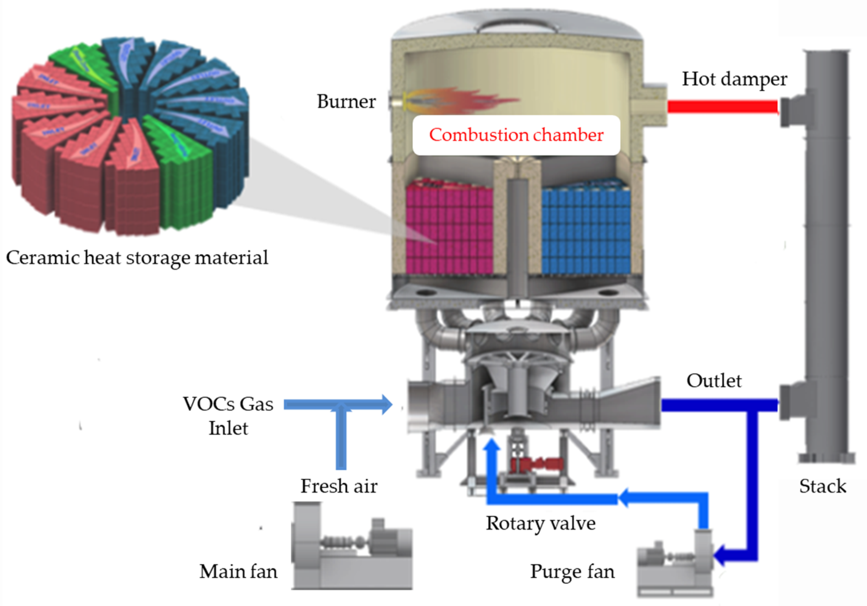
2.1. 100 and 10 CMM RTO Design

In the existing heat storage-type combustion oxidizer, a rotary distributor in the form of a cylindrical drum with an inlet and an outlet is predominantly used. However, prolonged use of this drum-type rotary distributor can result in operational issues such as rotation stoppage due to high temperatures, thermal expansion, and dust accumulation [4]. Additionally, to minimize friction within the air distribution unit, the air-blocking components in contact with the rotating part are arranged with a 2–3 mm gap. This gap allows VOC gas to enter, mix with the treated exhaust gas, and be released through the final outlet, thereby reducing VOC treatment efficiency. To address this issue, it is crucial to control the gas flow between the rotating and air-blocking parts and to develop a design with superior durability [13,14]. Table 1 presents the specifications of the 100 CMM and 10 CMM-class heat storage-type combustion oxidizer. The 10 CMM design represents a reduced standard that can be utilized according to 100 CMM design method.
Table 2 presents the energy balance calculations for the 100 CMM-class heat storage-type combustion device material based on the processing gas flow rate and VOC concentration, as outlined in the design criteria in Table 1. The VOC calorific value treatment standard is expressed in terms of the toluene calorific value equivalent.
Based on the design data from Table 1 and Table 2, Figure 2 illustrates the 3D model of the RTO, which comprises contaminated gas inlets, purge gas inlets, rotators, rails, rail covers, combustion chambers, heat storage material support structures, and treated gas outlets.
In Figure 2, the upper and lower surfaces of the chamber are supported by a rail cover set, and the rotation of the intermediate ceramic plate causes reflux into the gap between the foreign substance and the chamber wall suspension. Foreign substances and reflux phenomena can cause the discharge of unburned VOC gasses into the atmosphere, which can degrade system performance. To overcome this, the chamber is designed to maintain stable gas inflow and outflow distribution through detailed design of the rotating part of the intermediate plate. However, prolonged use may cause the parts associated with the upper and lower rails to wear out. The gap adjustment mechanism, consisting of a turnbuckle, is used to adjust the gap between the upper and lower plates, and the intermediate plate and its surrounding configuration are designed as a modular package to facilitate holding and disassembling of the lower plate from the upper plate. At this time, a fixing mechanism is installed above and below the intermediate plate to prevent deflection of the gap by repulsive force, thereby reducing the wear on the rail-related parts and extending the lifespan. This can be done so that the RTO performance can be maintained even when the parts are worn out.

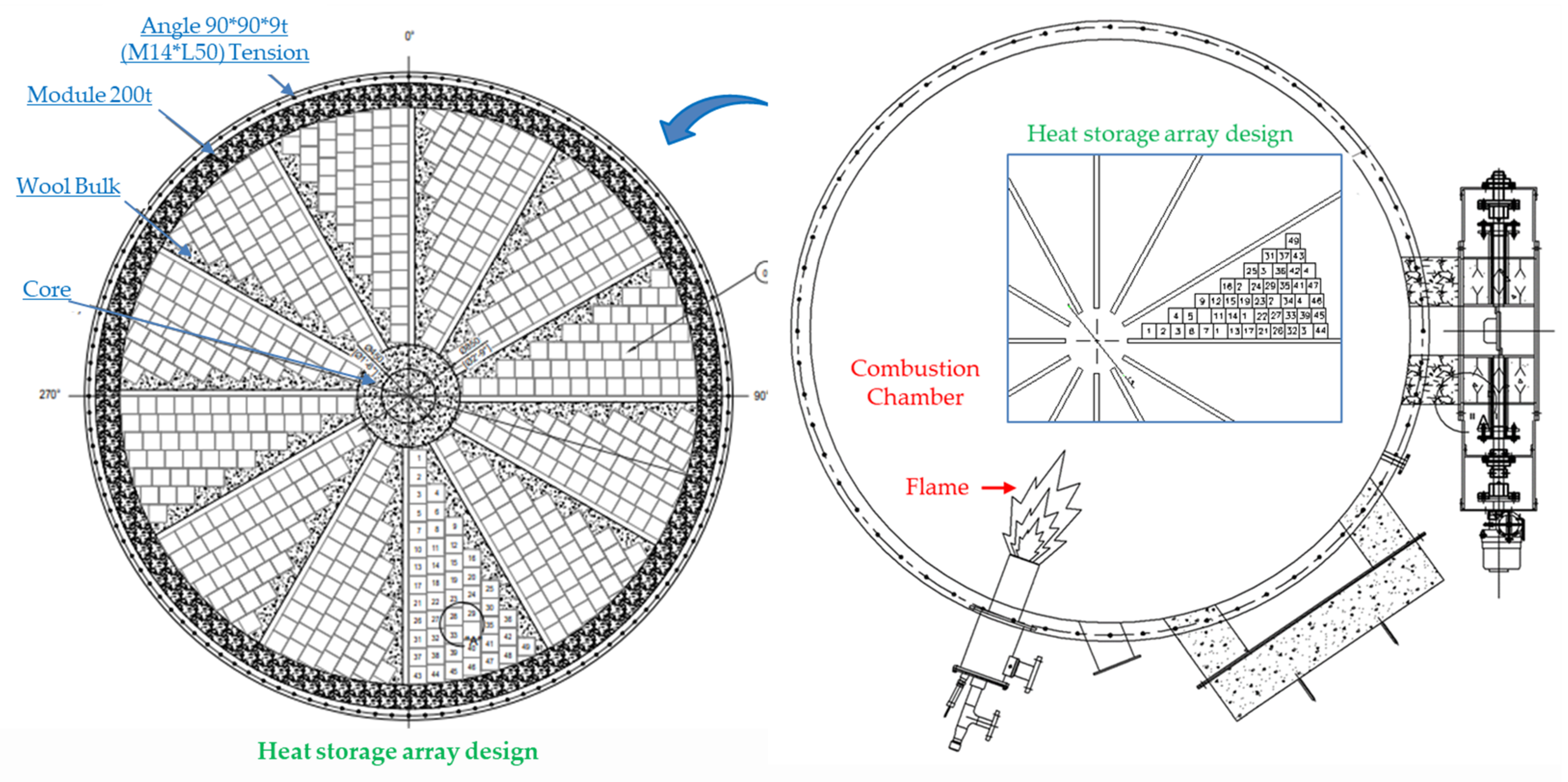
2.2. Redesign of Rotary Distributor and Disk Rotating Plate

In Figure 2, for the normal operation of the RTO combustion chamber, the gas burner was designed with a diameter of 125 mm, and the outlet was sized at 650 mm × 650 mm to efficiently discharge high-temperature waste heat. The combustion chamber heat storage material is specified as a ceramic block with a thickness of 250 mm. Considering the residence time of the treatment gas and the thickness of the insulation, the combustion chamber was designed with an outer diameter of 2530 mm and a height of 1875 mm. Long-term use of the heat storage material may result in damage due to thermal shock and fatigue, necessitating periodic inspection and replacement. Figure 3 illustrates the rotary distributor redesign that supports the disk rotating plate’s movement and the disk that directs the flow of VOC gas.
Figure 4 illustrates the arrangement design of the heat storage material within the combustion chamber. Although a cylindrical structure is used for the heat storage material filling section, the ceramic filling arrangement has been modified from the existing design to minimize unused areas and reduce the device size. This new arrangement design reduces the device diameter from Φ 2610 mm to Φ 2480 mm and improves the number of ceramic fillings by reducing a total of 60 units (5 per zone × 12 zones = 60) compared to the previous method.
Figure 5 is a design diagram of the VOCs gas inlet and outlet unit with the purge inlet in the rotary part located at the bottom of the combustion chamber of Figure 3 and Figure 4 and it shows the analysis conditions at the main inlet, outlet, and purge inlet of the rotary according to chamber combustion conditions based on Table 1 and Table 2.
Based on Table 1 and Table 2, the specifications of the burner are selected with consideration of energy efficiency. The combustion efficiency within the chamber can be influenced not only by the efficiency of the burner but also by the inconsistent supply of VOC gas from the plant. The role of maintaining the chamber temperature at 800 degrees Celsius and removing more than 95% of harmful gasses is supported by supplying LNG gas when the VOC gas supply is insufficient. Although the use of LNG increases operational costs, it is necessary to achieve the goal of harmful gas removal. Future research should focus on maintaining a consistent temperature within the chamber [15].
Although the specified temperature of the combustion chamber varies slightly from country to country, it generally operates within the range of 800 to 950 degrees Celsius, achieving a VOC removal efficiency of 95% or higher using a burner. The thermal efficiency (η) of the combustion chamber is calculated using Equation (1). When the combustion chamber temperature is 800 degrees Celsius, a removal efficiency of 95% or more can be obtained [13].
η = T C T e T C T i × 100   %
Here, T C represents the RTO combustion chamber temperature, T e represents the stack emission temperature, and T i represents the inlet temperature of the RTO.
In the air pollution process test method, the concentration of the facility inlet gas and exhaust gas is simultaneously measured using the total hydrocarbon (THC) analysis method to calculate the VOC reduction rate, as shown in Equation (2), below.
V O C   r e d u c t i o n   r a t e % = 1 o u t p u t   T H C   c o n c e n t r a t i o n i n p u t   T H C   c o n c e n t r a t i o n × 100  
The RTO combustion chamber utilizes LNG gas for combustion and the amount of combustion energy required is determined based on the LNG price per cubic meter [13]. Given the LNG price based on Table 1, the calorific value and combustion energy can be calculated. At this time, a hot bypass leak occurs. Considering the energy loss of the purge and combustion fan, the heating energy at high temperatures is calculated as follows:
Heating energy = Q × 0.15 × (complexion room temperature − incoming temperature) × (1 − heat recovery rate) × 60 min/h

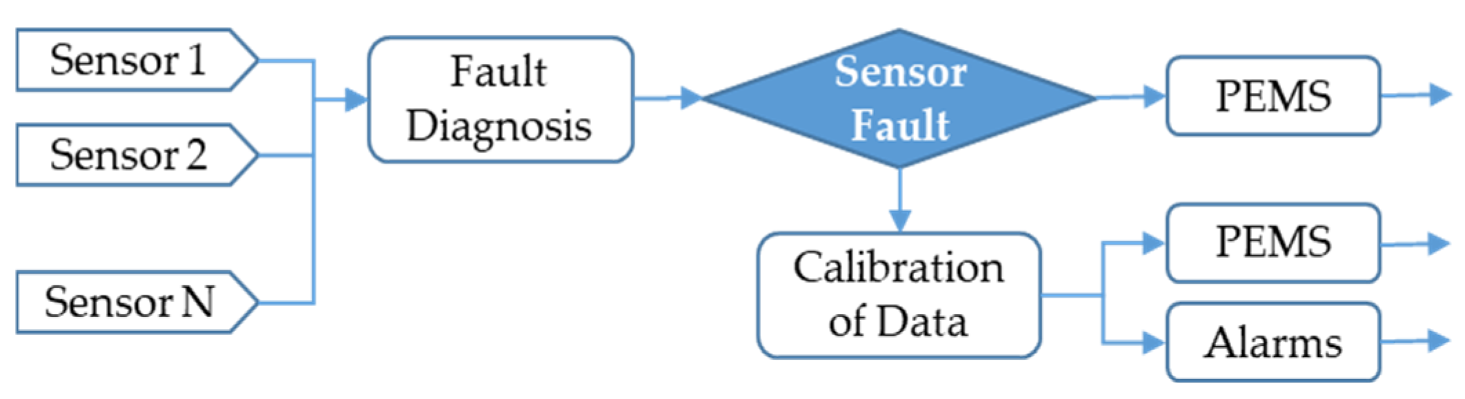
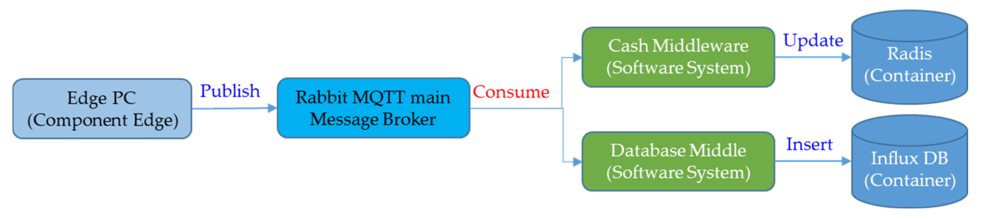
2.3. Intelligent PLC Operation Based on Edge-IoT

Figure 6 shows the configuration of the 100 CMM RTO device using the design process discussed so far. The combustion chamber main body with the ceramic array and the burner are connected and implemented to introduce exhaust gas from the rotary fan and the production site coating machine. The overall control and operation of the system are integrated to be operated through a programmable logic controller (PLC) device and the operation is tested according to trip conditions. The monitoring unit is connected to the sensor function of the RTO, and depending on the driving information, a stop or warning function is displayed on the screen for visual visibility.
Figure 7 shows sensors 1 to 9 connected to detect abnormal behavior of the RTO device. It is connected to the PLC device and plays an important role in the performance of the trip function through Table 3. Based on the Edge-IoT circuit at the bottom of the PLC unit, four switch sensors and buzzers are connected to the power switch sensor, the internal thermal sensor of the chamber, and the buzzer from trip A to D. The trip A to D switches occur according to the RTO operation, turning off the power switch, turning on/off functions according to the temperature range, and notifying the warning signal (Buzzer) according to the sensor threshold. Log data are received by streaming at each sensor location and the function of the trip device is implemented using an intelligent algorithm.
Table 3 shows the PLC and Human Machine Interface (HMI) mapping list. In the RTO operation, the analog value becomes a nine-sensor analog interface (AI). The trip information has 12 Boolean algebra information and is a digital interface (DI) that notifies a warning according to logic 0 or 1.
In the mapping list in Table 3, the analog group is set to execute RTO and builds a database through an edge-IoT connection. The established sensor DB supports countermeasures for the type and cause of failure of the device. Table 4 shows examples of failure phenomena for the trip type.
As can be seen in Table 4, various trip types of RTO devices occur depending on various causes of failure. The sensor data of the RTO device acquired through Sensor-IoT is divided and the trip function is performed based on the failure conditions in Table 4. At this time, the data acquired through the RTO operation is learned for a long time, and failure prediction and system safety are evaluated through the Predictive Emission Monitoring System (PEMS) algorithm of Figure 8. Therefore, the sensor data point of the RTO system is very important, and the reliability of the sensor can be increased by using the correction value when the device fails by taking the measurement sensor related to combustion efficiency as an example. Figure 8 is a flowchart of a correction algorithm when the measurement sensor fails, and the combustion efficiency can be evaluated according to the system operation. The sensor Log data acquired through streaming is segmented and becomes an important performance evaluation factor of the PEMS algorithm operation through an intelligent learning effect.
For IoT node failures or intermittent long-distance network connection problems, local fault tolerance needs to be implemented to preserve the system state locally at the edge. To address this issue, we propose CEF-IoT, a new fault-tolerant architecture for IoT applications using cloud technology-based edge computing. The Edge-IoT architecture consists of three layers: application isolation, data transfer, and multi-cluster management. Based on this layer design, the architecture can deploy computing to the edge or cloud without the need for source code modification. The CEF-IoT architecture is designed to provide unified multi-cluster management that provides fault tolerance to both edge and cloud-side clusters and enables failover in large, interconnected networks. Furthermore, CEF-IoT’s separate clusters for edge and cloud allow edge devices to operate independently even if they are disconnected at the cloud backend. Thus, the architecture operates in degradation mode, even when the cloud is disconnected. The architecture is logically constructed from the underlying technique using three abstraction layers [17]. Figure 9 shows applications with application separation, data transfer, and multi-cluster management layers with four PC 1–4 processing steps. It describes PC processing containers, ET edge topics, CT cloud topics, EN edge nodes, and CN cloud nodes.
Based on Figure 9, Figure 10 shows a configuration diagram that catches data in real time according to the message queue and uses large amounts of data as needed in the database. It also implements middleware services that are registered or modified in each database by consuming messages in the message queue.
Based on Figure 10, RTO’s monitoring system synchronizes the Redis database with the Influx database and stores data in real time. Figure 11 shows the overall DB configuration diagram leading to remote maintenance services based on Table 3 and Table 4 and Figure 8. MQTT is a message-queue data pipeline that delivers information collected from edge IoT terminals to the collector in a message-queue method [18,19,20]. In the synchronized DB, TBL_COM_CODE is used as a common code, TBL_IOT_MAP is used for IOT processing, and TBL_UNIT is used for device mapping. It then detects whether it is in an abnormal state and generates a path or displays the result to the user.

3. Experimental Results

3.1. Economic Design Processes of Combustion Chamber

Table 5 is the result of calculating the heat recovery energy, the amount of heat storage material, and the pressure loss in the combustion chamber based on Table 1 and Table 2. In this setup, the heat loss volume is 40 m3 and the total volume of the heat storage material is 2 m3.
Table 6 presents an economic analysis of monthly maintenance costs derived according to the design specifications based on Table 1, Table 2 and Table 5. The monthly maintenance costs are calculated based on a combustion energy of 117,580 kcal/h and a solvent calorific value of 221,554 kcal/h. It is suggested that the calculated values may vary slightly depending on the exchange rate, fuel price, and energy policy of each country.
When the economic review is completed through Table 5 and Table 6, the RTO is designed through Figure 2, Figure 3 and Figure 4. Particularly, Figure 3 is designed to minimize the risk of damage due to load when used for a long time in an intermediate plate designed with a central flat disk structure.

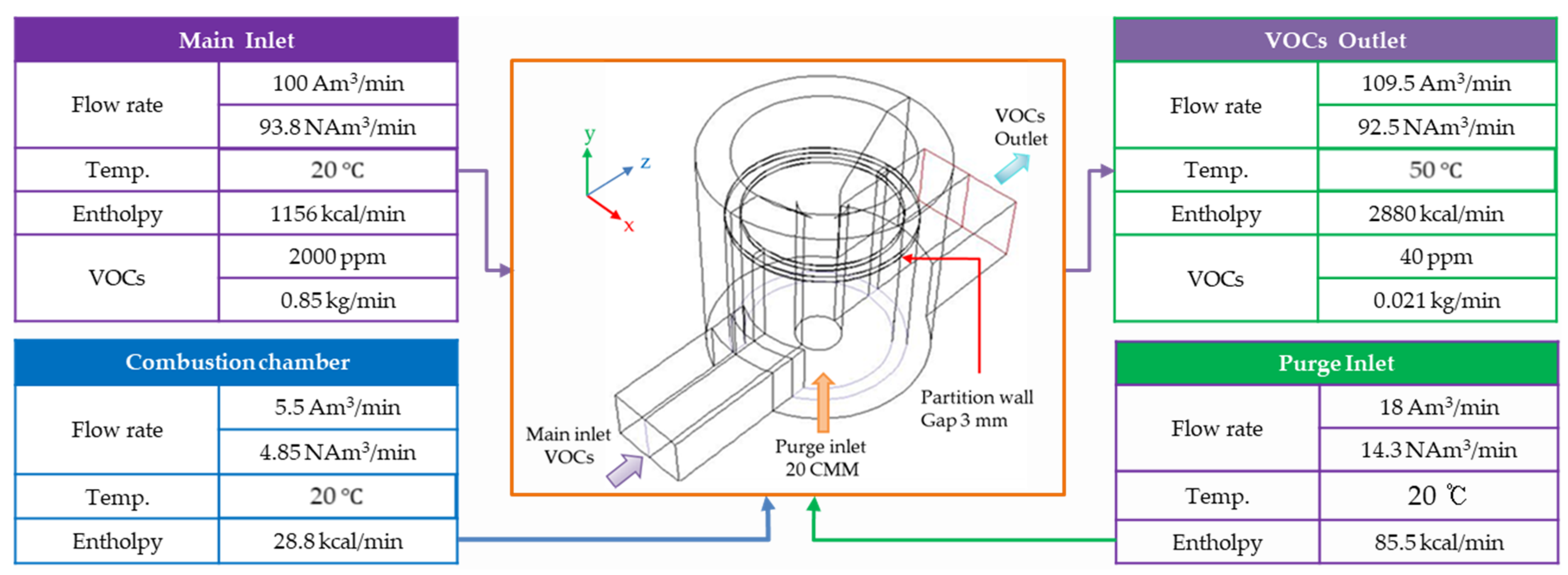
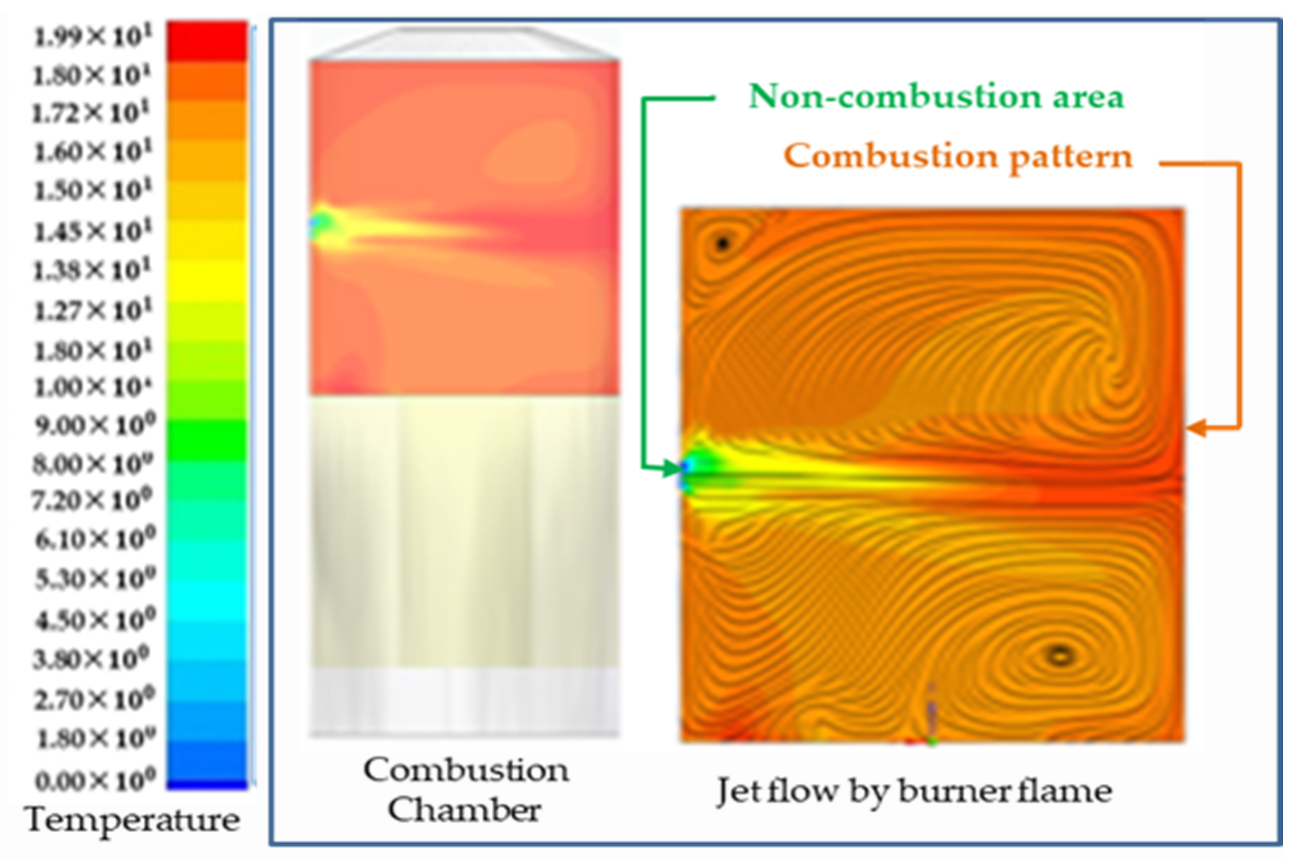
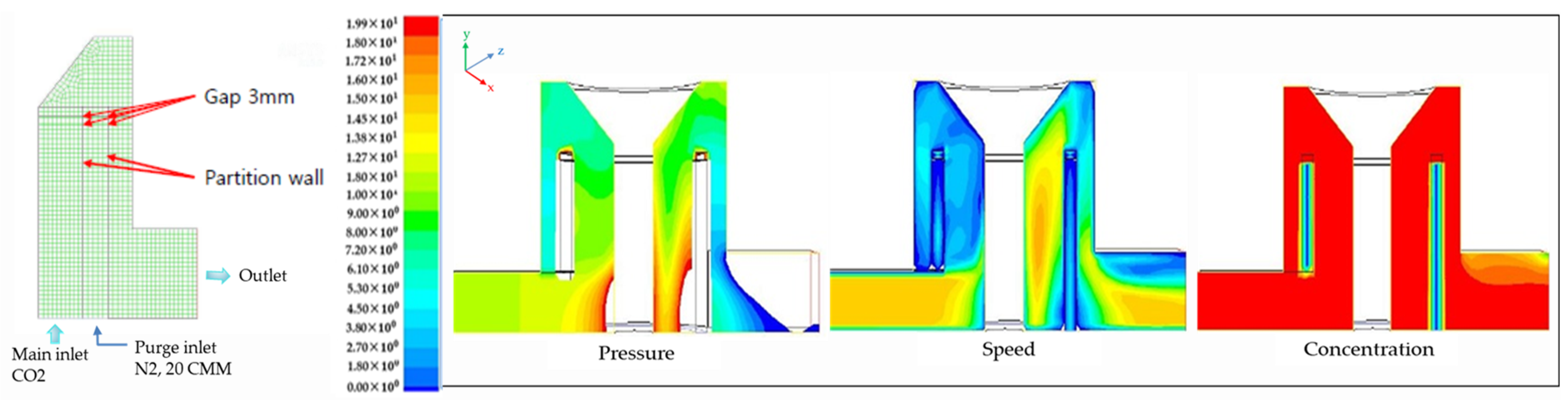
3.2. Flowability Analysis of Combustion Chamber and Rotary VOCs Gas

In Figure 4 and Figure 5, 3.3 m3/min is considered the air volume that can be processed per ceramic unit, and the number of disks is determined based on the ceramic arrangement table. Although the designed RTO capacity is 100 CMM, the actual experiment simulates an air volume of 120 CMM. The RTO diameter used for this experiment is 2180 mm, with 240 ceramic units installed. The interrelationship between factors such as treatment air volume, ceramic arrangement length, and RTO diameter is taken into account, and a gas flow analysis within the RTO chamber is conducted through simulations based on criteria steps.
Figure 12 shows the temperature distribution within the combustion chamber and the combustion behavior, including the generation of unburned VOC gas, as influenced by the burner’s heat. A jet flow is formed according to the burner’s flame pattern, resulting in a curved shape that indicates temperature non-uniformity. Additionally, the green area at the center of the jet flow represents the section where VOC gas remains unburned.
Based on Figure 12, Figure 13 is a graph that simulates temperature changes according to the combustion chamber burner operation. It shows a stable state, an unstable state, and other start and end states at 800 degrees. The initial unstable state appears in the step of calculating the temperature in the combustion chamber and the input of harmful gasses.
Figure 14 shows the flowability of gas flows in and out of the rotating part according to the operation and characteristics of the combustion chamber based on Figure 5.
It displays the range from the lowest values, represented in blue, to the highest values, represented in red, according to the units of pressure [Pa], speed [m/s], and concentration [g-mol/kg], respectively. Table 7 presents the values measured after the RTO reaches a stable operating state, as illustrated in Figure 15.

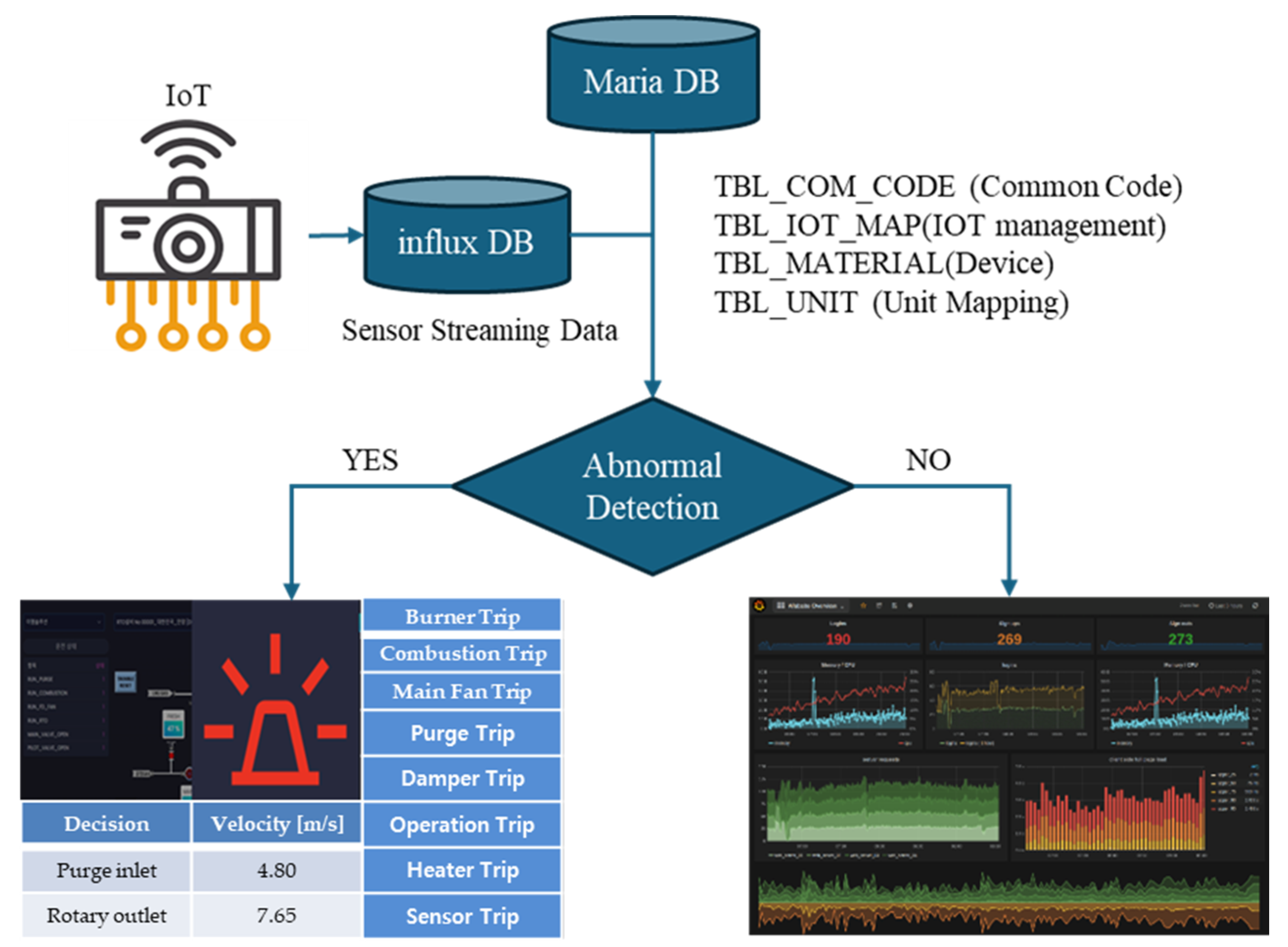
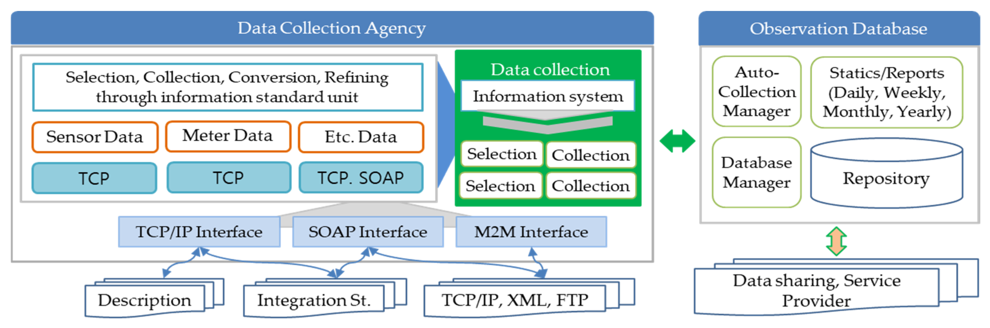
3.3. Data Visualize for RTO Analysis

The data obtained from the sensors are data generated by physical sensors such as temperature, flow rate, and pressure of the RTO. By combining these, the software calculates new index values such as the current status of RTO emissions by applying the concept of a virtual sensor. As it becomes possible to collect real-time data from field operations, prediction algorithms can be applied using various artificial intelligence machine learning technologies and acquired data to preserve the prediction of the system. According to Figure 10 and Figure 11, Figure 15 shows that sensor data from nine channels build a sensor database on the server. The right shows the database to observe.
Visualization was implemented through the Edge-IoT architecture for collecting and determining real-time state information for remote maintenance of heat storage combustion non-acid devices. The Edge-IoT architecture system interfaces with PLCs that control RTO operation monitoring to transmit real-time data to remote servers and builds a database by analyzing channel data received through IoT. In the case of high-speed data from the edge and smart sensor corps, it is configured to transmit results remotely after signal processing, enabling efficient operation of the system by reducing the load on the edge-IoT side and cloud side networks.
In Figure 15, the data collected by the data collection agency is stored in the observation database in real time. For this reason, automatic collection managers and database managers subdivide it according to the type of sensor input information in Figure 7. Meanwhile, according to data sharing, service providers statistically analyze data by day, week, month, and year. They are connected through the TCP/IP interface, SOAP interface, and M2M interface to analyze information such as burner temperature, main input and output, temperature such as purge input, damper state, etc.

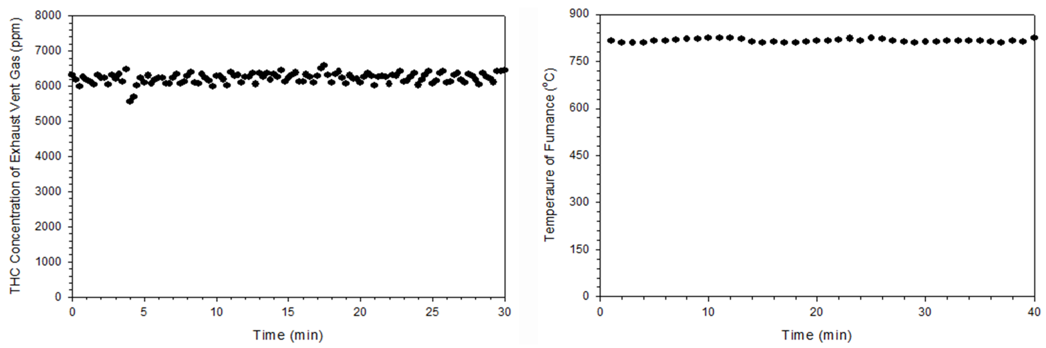
3.4. VOCs Gas Emission Test Based on Film Coating Device

For field experiments, the concentration of VOC gas emissions generated from the coating film production system is tested. The validity of the experiment is verified through the nationally accredited Korea Testing Laboratory (KTL). Figure 16 shows the gas concentration values emitted from the film drying and printing sections of the coating film production system.
The VOC concentration in the drying section ranged from a maximum of 3979 ppm to a minimum of 593 ppm, with an average total hydrocarbon (THC) concentration of 2567 ppm. In the printing section, the concentration ranged from a maximum of 2170 ppm to a minimum of 686 ppm, with an average THC concentration of 1260 ppm.
Based on Table 7, the VOC gas entering the RTO device from the plant passes through a layer of ceramic heat storage material, is preheated in the rotary input and chamber, is combusted with a burner, and is then discharged through the stack in that order. During this process, the heat generated in the chamber oxidizes and decomposes the gas at temperatures ranging from 700 to 850 °C. The exhaust gas then passes through the heat storage material on the outlet side, storing high-temperature waste heat in the ceramic. Heat storage and dissipation occur alternately at regular intervals according to the operating cycle. At this stage, the heat recovery efficiency exceeds 95%, and the treatment efficiency achieves over 97.898% oxidation and decomposition, resulting in the release of harmless and odorless clean gas at 60 °C. Table 8 presents the test results based on the data in Table 6, showing the VOC removal efficiency calculated from THC and the actual nitrogen oxide measurements using Equations (2) and (3).
After the combustion chamber operating temperature reaches 800 °C, it decreases to 750 °C at 50 Hz due to the site exhaust gas blower. At this point, when the burner is activated to restore the temperature to its normal level, the combustion chamber temperature rises and fluctuates between 799 °C and 804 °C, with a deviation of approximately 5 °C. This fluctuation is caused by the irregular VOC emissions from the plant, which require additional energy to activate the burner in order to maintain the RTO chamber temperature. This factor is crucial in assessing the interoperability and cost-efficiency between the plant and the RTO device. In the RTO simulation, the average concentration of the inlet gas, based on the operating temperature of the combustion chamber, was 6224 ppm (THC), while the RTO combustion chamber temperature was 815 °C. The THC concentration exhaust and combustion chamber temperature fluctuated between a minimum of 808 °C and a maximum of 825 °C, as shown in Figure 17.

4. Conclusions

In this paper, we implement an improved a 100 CMM heat storage oxidation device (RTO) for low-emission combustion capable of treating more than 95% of volatile organic compound (VOC) gas. The existing RTO system achieved energy efficiency with VOCs and heat recovery by utilizing a cylindrical drum structure that repeatedly introduced and discharged VOC gas into the rotating disk. However, the driving force applied to the rotating disk in the RTO combustion chamber increases wear around the rotating shaft, and the untreated gas is mixed and discharged due to the channeling phenomenon at the rotary part connected to the inlet of the combustion chamber. In addition, long-term use at a high temperature of 800 °C may cause operational problems such as rotation stop or explosion due to the accumulation of pollutants, dust, and thermal expansion. To solve this problem, an improved rotating plate drive device was designed while ensuring normal operation of the RTO combustion chamber. Considering that the temperature of the combustion chamber can rise up to 920 °C during high concentration VOC gas treatment, the gas burner was designed with a diameter of 125 mm and the outlet was designed with a diameter of 650 mm × 650 mm to effectively discharge high temperature waste heat. The heat storage material in the combustion chamber consisted of a ceramic block thickness of 250 mm, and the outer diameter and height of the chamber were set at 2530 mm and 1875 mm, respectively, in consideration of the gas residence time and the thickness of the insulation.
In addition, an intelligent PLC was constructed based on trip data according to RTO monitoring, and the evaluation and efficiency of safe operation were proposed through database and visualization of streaming sensor data. Empirical experiments conducted with an RTO system integrated into a film coating plant show that changes in VOC removal efficiency, nitrogen oxide emission concentration, and THC (total hydrocarbon) concentration achieve removal efficiency of over 98.0%.
In the future, we intend to contribute to research focusing on energy saving by presenting methods for evaluating the performance and economic feasibility of 100 CMM systems through simulation and optimization based on specific parameters and data.

Author Contributions

Supervision and conceptualization, project administration, H.-M.P.; formal analysis, H.-M.J.; methodology and synthesis, D.-H.L.; validation and resources, H.-N.P.; software and investigation, T.-Y.L.; visualization and design, J.-H.Y.; visualization, writing—original draft, writing—review and editing, D.-H.Y. All authors have read and agreed to the published version of the manuscript.

Funding

This research received external funding. This work was supported by Ministry of Trade, Industry and Energy of the Republic of Korea with the grant funded by the Korea Evaluation institute of Industrial Technology (Project No. 20023721).

Data Availability Statement

The original contributions presented in the study are included in the article, further inquiries can be directed to the corresponding author.

Conflicts of Interest

Authors Hoon-Min Park, Hyun-Min Jung, Dae-Hee Lee, Hei-Na Park and Tae-Young Lim were employed by the company Emsolution Co., Ltd. The remaining authors declare that the research was conducted in the absence of any commercial or financial relationships that could be construed as a potential conflict of interest. The company had no role in the design of the study; in the collection, analyses, or interpretation of data; in the writing of the manuscript, or in the decision to publish the results.

References

  1. Soumyabrata, R.; Arjun, C.; Sebastian, C.P. Thermochemical CO2 Hydrogenation to Single Carbon Products: Scientific and Technological Challenges. ACS Energy Lett. 2018, 3, 1938–1966. [Google Scholar] [CrossRef]
  2. Yoon, J.H. Transboundary Air Pollution and Global Governance: Singapore’s Network Strategy to Tackle the Indonesian Haze. Korean Soc. Reg. Stud. Repub. Korea 2016, 34, 51–79. Available online: https://www.dbpia.co.kr/Journal/articleDetail?nodeId=NODE08788063 (accessed on 22 November 2023).
  3. Bian, C.; Huang, J.; Zhong, B.; Zheng, Z.; Dang, D.; Okafor, O.C.; Liu, Y.; Wang, T. Autothermal Reforming of Volatile Organic Compounds to Hydrogen-Rich Gas. Molecules 2023, 28, 752. [Google Scholar] [CrossRef] [PubMed]
  4. Lee, H.J.; Chao, M.H.; Ko, D.R. Causative Substance and Time of Mortality Presented to Emergency Department Following Acute Poisoning: 2014–2018 National Emergency Department Information System. J. Korean Soc. Clin. Toxicol. 2021, 19, 65–71. [Google Scholar] [CrossRef]
  5. Hasegawa, T. Gas Turbine Combustion and Ammonia Removal Technology of Gasified Fuels. Energies 2010, 3, 335–449. [Google Scholar] [CrossRef]
  6. Hou, S.S.; Chiang, C.Y.; Lin, T.H. Oxy-Fuel Combustion Characteristics of Pulverized Coal under O2/Recirculated Flue Gas Atmospheres. Appl. Sci. 2020, 10, 13–62. [Google Scholar] [CrossRef]
  7. Sung, Y.M.; Kim, S.T.; Jang, B.H.; Oh, C.Y.; Jee, T.Y.; Park, S.I.; Park, K.S.; Chang, S.Y. Nitric Oxide Emission Reduction in Reheating Furnaces through Burner and Furnace Air-Staged Combustions. Energies 2021, 14, 1599. [Google Scholar] [CrossRef]
  8. Park, H.M.; Yoon, D.H.; Jung, H.M.; Jeon, D.H. Development of Porous Plate Scrubbers and Simulation of IPA Treatment Efficiency to Improve Dust Collection and Deodorization. Saf. Cult. Res. 2021, 13, 339–349. [Google Scholar] [CrossRef]
  9. Sadkin, I.; Mukhina, M.; Kopyev, E.; Sharypov, O.; Alekseenko, S. Low-Emission Waste-to-Energy Method of Liquid Fuel Combustion with a Mixture of Superheated Steam and Carbon Dioxide. Energies 2023, 16, 5745. [Google Scholar] [CrossRef]
  10. Choi, B.S.; Yi, J. Simulation and Optimization on the Regenerative Thermal Oxidation of Volatile Organic Compounds. Chem. Eng. J. 2000, 76, 103–114. [Google Scholar] [CrossRef]
  11. Khakimova, L.; Popov, E.; Cheremisin, A. Insights on In Situ Combustion Modeling Based on a Ramped Temperature Oxidation Experiment for Oil Sand Bitumen. Energies 2023, 16, 6738. [Google Scholar] [CrossRef]
  12. Jeon, D.H.; Jeng, S.W. Pre-treatment Method of Irregular Process Emissions for High-Efficiency Combustion Treatment of Volatile Organic Compounds. In Proceedings of the Autumn Conference of the Korea Gas Association, Daegu, Republic of Korea, 21–25 June 2021. [Google Scholar]
  13. Yoon, D.H.; Han, B.S.; Lim, T.Y.; Yang, E.C. Implementation of 100CMM Thermal Storage Combustion Oxidizer for VOCs Reduction. In Proceedings of the 2022 International Conference on Control, Automation and Systems, Busan, Republic of Korea, 27 November–1 December 2022; pp. 1–25. Available online: https://ieeexplore.ieee.org/xpl/conhome/10003266 (accessed on 26 April 2024).
  14. Park, H.M.; Jung, H.M.; Lee, D.H.; Lim, T.Y.; Yoon, D.H. VOCs Oxidation Treatment and Waste Heat Recovery Technology through the Implementation of Heat Storage Type Combustion Oxidation Device. Korean J. Saf. Cult. 2022, 17, 285–298. [Google Scholar] [CrossRef]
  15. Park, H.M.; Yoon, D.H.; Jeon, D.H.; Min, H.K. Nitrogen Oxide Reduction Type Regenerative Thermal Oxidation System and Nitrogen Oxide Reduction Method Thereof. U.S. Patent US20230228205A1, 16 July 2024. [Google Scholar]
  16. Park, H.M.; Yoon, D.H.; Jeon, D.H.; Min, H.K. Multistage Variable Type Waste Heat Storage and Recovery Apparatus and Method Thereof. U.S. Patent US2023/0228500A1, 20 July 2023. [Google Scholar]
  17. Korea Testing Laboratory (KTL), Republic of Korea. Available online: www.ktl.re.kr (accessed on 26 April 2024).
  18. Javed, A.; Heljanko, K.; Buda, A.; Framling, K. CEFIoT; A fault-tolernant IoT Architecture for Edge and Cloud. In Proceedings of the 2018 IEEE 4th World Forum on Internet of Things (WF-IoT), Singapore, 5–8 February 2018. [Google Scholar]
  19. Rabinovich, M.; Xiao, Z.; Aggarwal, A. Computing on the Edge: A Platform for Replicating Internet Applications. In Web Content Caching and Distribution; Springer: Dordrecht, The Netherlands, 2024; pp. 57–77. [Google Scholar]
  20. Kreps, J.; Narkhede, N.; Rao, J. Kafka: A Distributed Messaging System for Log Processing. In Proceedings of the NetDB 2011, Athens, Greece, 12 June 2011; pp. 1–7. [Google Scholar]
Figure 1. The evolution of the heat storage combustion oxidation device.
Processes 12 02814 g001
Figure 2. Configuration of RTO 3D model.
Processes 12 02814 g002
Figure 3. Redesign of rotary distributor and disk rotating plate.
Processes 12 02814 g003
Figure 4. The heat storage agent arrangement design in chamber.
Processes 12 02814 g004
Figure 5. Design of rotary part and analysis conditions.
Processes 12 02814 g005
Figure 6. Configuration of 100 CMM RTO system.
Processes 12 02814 g006
Figure 7. PLC trip switch connected to sensor unit.
Processes 12 02814 g007
Figure 8. Flowchart of a correction algorithm to sensor fails and PEMS.
Processes 12 02814 g008
Figure 9. Application layer of Edge-IoT.
Processes 12 02814 g009
Figure 10. Configuration diagram that catches data in real time.
Processes 12 02814 g010
Figure 11. The overall DB configuration diagram.
Processes 12 02814 g011
Figure 12. Jet stream and combustion pattern of VOC gas.
Processes 12 02814 g012
Figure 13. Simulation of temperature changes to the combustion chamber burner operation.
Processes 12 02814 g013
Figure 14. Flowability analysis of gas flows.
Processes 12 02814 g014
Figure 15. Configuration of measured database.
Processes 12 02814 g015
Figure 16. VOCs concentration discharged from the coating film system.
Processes 12 02814 g016
Figure 17. The THC concentration exhaust and combustion chamber temperature fluctuation.
Processes 12 02814 g017
Table 1. The design specifications comparison of a 100 CMM and 10 CMM RTO.
ProcessUsage SpecificationUnitDesign Data
100 CMM10 CMM
Main fanAir volumem3/min10010
PressuremmAq400400
PowerkW152.2
CurrentA39.55.8
Purge fanAir volumem3/min202
PressuremmAq700500
PowerkW5.52.2
CurrentA14.55.8
Combustion fanAir volumem3/min81
PressuremmAq800700
PowerkW3.71.5
CurrentA9.73.9
BurnerCapacitykcal/h100,00015,000
Fuel (LNG Gas)kcal/Nm3--
Supply pressuremmAq25002500
Usage pressuremmAq500500
Combustion air pressuremmAq800700
RotaryPowerkW1.50.75
CurrentA42
TemperatureCombustion chamber°C800800
Inlet temperature°C2020
Outlet temperature°C60 ± 360 ± 3
Thermal efficiency%9595
Substance material to be treated
(Toluene calorific value)
ppmVOCs~2000
-smoke (4 degrees or higher)
-Stench (over 4 degrees)
VOC generation kg/h43
Table 2. The emission design of VOC calorific value.
VOCEmission ConcentrationEmissionsUnit Combustion HeatAmount of Heat Burned
ppmkg/hkcal/kgkcal/h
Methacrylic acid2000435150221,540
Table 3. PLC–HMI mapping list for the RTO operating test.
Tag NameDescriptionTypeRangeI/O
Analog value Combustion chamber temp.real-AI
Combustion chamber valuereal-AI
Input temperaturereal-AI
Exhaust temperaturereal-AI
FD Fan: Frequency setting real0~60AI
FD FNA: Current valuereal-AI
Rotary: Frequency setting real0~60AI
Rotary: Current valuereal-AI
Fresh damper open valuereal0~100AI
Hot damper open valuereal0~100AI
Trip informationFD Fan Tripbool0 or 1DI
Rotatory Tripbool0 or 1DI
Purge Fan Tripbool0 or 1DI
Combustion Fan Tripbool0 or 1DI
Fresh Damper Tripbool0 or 1DI
Hot Damper Tripbool0 or 1DI
Combustion chamber overheatbool0 or 1DI
Combustion chamber: high bool0 or 1DI
Combustion chamber: lowbool0 or 1DI
Incoming temperature: High bool0 or 1DI
Exhaust temperature: High.bool0 or 1DI
In/Outlet GAS Tripbool0 or 1DI
Table 4. Trip type to failure phenomenon case.
Trip StyleOut of Order
Burner TripBurner off, Fresh Damper Close, Hot bypass Damper Close, RTO Fan Run, Purge Fan Run, Combustion Fan Run, Rotary Run, Main Fan Run
Combustion TripBurner off, Fresh Damper Open, Hot bypass damper Open, RTO Fan Stop, Purge Fan Stop, Combustion Fan Stop, Rotary Stop, Main Fan Run
Main Fan TripBurner off, Fresh Damper Open, Hot bypass Damper Open, RTO Fan Stop, Purge Fan Stop, Combustion Fan Stop, Rotary Stop, Main Fan Stop
Table 5. Design specifications of combustion chamber.
Heat Storage Material ItemsConfiguration MaterialDesign Specifications
Recovery energyHeat accumulator passing temperature735 °C
Heat storage material recovery calorific value1,911,341 Kcal/h
Heat storage materialHeat exchange rate31,856 Kcal/h
Total area of heat storage material2 m3
Pressure lossA heat storage material100 mmAq
Stack5 mmAq
Rotary3 mmAq
a sudden zoom45 mmAq
Etc.100 mmAq
Total253 mmAq
Table 6. Economic production based on monthly maintenance costs.
Economic ItemsMonthly Maintenance Costs
Normal heating fuel production802,106 kcal/h ÷ 15,000 kcal/Nm3·LNG × 0.5 h/day × 3 day/month × 700 $/Nm3·LNG = 56,147 $/month
Fuel production per hour0 day/month × 30 day/month × 700/Nm3·LNG
Total monthly fuel use cost: 56,147/month
Power usageTotal 63 kWh × 0.8 × 60 $/kWh × 24 h/day × 30 day/month = 2,177,280 $/month. Monthly electricity cost: 2,177,280 $/month
Monthly RTO Total fuel and power cost: 2,233,427/month
Table 7. The values measured after the RTO reaches a stable operating state.
GeometryVelocity [m/s]Pressure [mmAq]
Main inlet1424.45
Purge inlet4.803,711,178
Rotary outlet7.650.02
Table 8. VOSs gas test results.
SortationUnitInletOutletVOCs Reduction Rate (%)
Total hydrocarbon (THC)ppm6221.27155.5597.90
Nitrogen oxideppm-2.49-
Exhaust gas temperature°C-70.13-
Disclaimer/Publisher’s Note: The statements, opinions and data contained in all publications are solely those of the individual author(s) and contributor(s) and not of MDPI and/or the editor(s). MDPI and/or the editor(s) disclaim responsibility for any injury to people or property resulting from any ideas, methods, instructions or products referred to in the content.

