Article

A Study on the Influence of Natural Fractures in Tight Sandstone Reservoirs on Hydraulic Fracture Propagation Behavior and Post-Fracture Productivity

1
Exploration and Development Research Institute of Liaohe Oilfield Company, PetroChina, Panjin 124010, China
2
School of Petroleum Engineering, Xi’an Shiyou University, Xi’an 710065, China
3
Shaanxi Yanchang Petroleum (Group) Co., Ltd., Natural Gas Research Institute Branch, Xi’an 710065, China
*
Author to whom correspondence should be addressed.
Processes 2024, 12(12), 2813; https://doi.org/10.3390/pr12122813
Submission received: 20 November 2024 / Revised: 29 November 2024 / Accepted: 5 December 2024 / Published: 9 December 2024

Abstract

Tight sandstone gas reservoirs are rich in reserves and are an important part of unconventional oil and gas resources. However, natural fractures’ impact on hydraulic fracture propagation behavior and network formation mechanisms remain unclear. Exploring how to optimize fracturing parameters to maximize post-fracturing productivity requires further investigation. Therefore, this study focused on the characteristics of tight sandstone gas reservoirs and established a three-dimensional numerical simulation model for hydraulic fracture propagation and post-fracturing productivity using production history matching to validate the reliability of the model. Based on this model, this study investigated the influence mechanisms of natural fracture angles, density, and lengths on hydraulic fracture propagation behavior and network formation. The spatial distribution of hydraulic fracture widths in three dimensions is also explored. When natural fracture angles are lower, a greater number of natural fractures are activated, leading to more developed secondary hydraulic fractures and the formation of complex fracture networks. Hydraulic fractures tend to penetrate directly through high-angle natural fractures. Single-well cumulative gas production increases initially with increasing natural fracture angles, then decreases, but increases with higher natural fracture density and length. Optimal fracturing in areas with longer natural fractures, lower angles, and higher density distribution enhances single-well productivity effectively.

1. Introduction

Currently, conventional oil and gas resources are gradually decreasing and depleting, while China’s demand for petroleum and natural gas is increasing year by year, leading to an escalating dependence on foreign sources. According to statistical data released by the National Bureau of Statistics of China, in 2023, China’s crude oil and natural gas production amounted to 208 million tons and 229.71 billion cubic meters, respectively. However, imports of crude oil and natural gas reached 564 million tons and 165.56 billion cubic meters, resulting in external dependence rates of 72.9% and 40.09%, respectively [1]. Therefore, intensifying the development of unconventional oil and gas resources, such as tight sandstone gas, is essential to alleviate the imbalance between supply and demand in China’s oil and gas sector. The Sulige Gas Field, as China’s largest tight sandstone natural gas field, boasts abundant reserves. However, due to its characteristics of low porosity, low permeability, low abundance, and strong heterogeneity, individual wells typically lack natural productivity and must rely on hydraulic fracturing technology to achieve industrial oil and gas production [2]. Hydraulic fracturing technology stands as the primary enhancement technique in current petroleum engineering, with nearly 80% of oil and gas resources in the United States obtained through this method [3]. Hydraulic fracturing involves injecting fracturing fluid into the wellbore using high-pressure pumps at the surface. When the injection rate of fracturing fluid exceeds the reservoir’s ability to absorb it, the bottomhole pressure rises continuously. Upon surpassing the fracturing pressure of the adjacent reservoir rock near the wellbore, fractures form. Proppants suspended in a carrier fluid are then injected into the reservoir to support these fractures, keeping them open and allowing them to propagate. Finally, the fracturing fluid flows back, leaving the fractures propped open by the proppants. This process creates one or more fractures in the reservoir with specific geometric dimensions and conductivity, thereby enhancing the production capability of individual wells [4]. Hydraulic fracturing technology has matured significantly and encompasses a variety of methods. Among these, the segmented multi-cluster fracturing technique in horizontal wells, known for its effective reservoir modification, has become a key technology in contemporary hydraulic fracturing. It is widely applied in regions such as the Ordos Basin, Songliao Basin, and Tarim Basin.
Research on the impact of natural fractures on hydraulic fracturing primarily focuses on experimental studies and numerical simulations. Fu et al. (2016) [5] conducted laboratory experiments to explore the interaction between hydraulic fractures and natural fractures with varying cementation strengths, finding that hydraulic fractures can penetrate fully and strongly cemented natural fractures. Wen et al. (2016) [6] designed a device to simulate complex fracture networks in shale reservoirs, investigating proppant migration and settling patterns. Fatahi et al. (2017) [7] combined experimental and discrete element simulations to examine how the cementation degree and natural fracture angle affect hydraulic–natural fracture interactions. Wan et al. (2018) [8] used true triaxial experiments to classify interaction patterns into five types: arresting, bypassing, diversion, vertical extension, and vertical extension followed by diversion. Yildirim et al. (2019) [9] integrated true triaxial experiments with X-site simulations to assess how fluid velocity and viscosity impact these interactions. Julia et al. (2019) [10] incorporated Discrete Fracture Networks (DFNs) into hydraulic fracture propagation models to improve simulation reliability. Dehghan (2020) [11] studied six interaction modes using true triaxial experiments to evaluate their effects on the hydraulic fracture length. Liu et al. (2022) [12] investigated the influence of the natural fracture dip angle on hydraulic fracture propagation in tight reservoirs, showing that hydraulic fractures tend to penetrate fractures with larger dip angles. Zhang et al. (2023) [13] analyzed how natural fractures affect fracture network complexity using true triaxial experiments. The experimental results provide valuable insights into the fracture propagation behavior in tight sandstone reservoirs, but the current experimental methods are unable to assess the impact mechanism of complex fracture morphology on post-fracturing productivity.
In numerical simulations, Gonzalez et al. (2015) [14] used numerical methods to explore the effects of natural fractures, fluid viscosity, and differential stress on complex fracture network morphology. Guo et al. (2015) [15] developed an interaction model to simulate hydraulic fracture expansion under varying differential stresses and natural fracture dip angles. Wu and Olson (2016) [16] established a model for complex fracture network propagation, showing that hydraulic fracture trajectories are more controllable when intersecting natural fractures at smaller angles. Chong et al. (2017) [17] constructed a coupled hydro-mechanical model to analyze reservoir fracture network formation under different natural fracture densities. Chen et al. (2017) [18] used global cohesive elements to simulate interactions between hydraulic and natural fractures. Taleghani et al. (2018) [19] employed the cohesive zone model (CZM) to simulate hydraulic fracture propagation, finding that fracture angle and cementation properties of natural fractures influence hydraulic fracture paths. Shrivastava et al. (2018) [20] conducted 3D studies on stress field changes around fractures during interaction and their effect on propagation paths. Li et al. (2020) [21] used extended finite element methods to study how natural fractures and bedding planes influence fracture network morphology, concluding that a random fracture distribution promotes complex networks. Zhao et al. (2021) [22] developed a dynamic propagation model with cohesive zone elements to analyze how natural fracture characteristics affect hydraulic fracture expansion. Dong et al. (2021) [23] combined extended finite element methods (XFEM) with true triaxial experiments to model hydraulic fracturing in shale reservoirs, examining how natural fracture orientations impact fracture network geometry. Xiong and Ma (2022) [24] developed a stochastic fracture expansion model to simulate hydraulic fracture behavior in formations with developed natural fractures. Hu et al. (2023) [25] used the TOUGHREACT-FLAC3D simulator to study the effects of construction and natural fracture parameters on hydraulic fracture interactions. Wang et al. (2024) [26] created a fully coupled fluid–solid numerical model to simulate hydraulic fracture propagation, analyzing the impact of fracture cement strength, fluid viscosity, and induced stress fields on fracture interaction and expansion. Different numerical methods have been used to simulate fracture propagation under complex rock mass conditions. The aforementioned numerical simulation studies provide important insights into the influence of natural fractures on hydraulic fracture propagation. However, integrating fracture propagation results into productivity simulation analysis presents a significant challenge in numerical methods, and most studies have not yet achieved this.
The above studies indicate that natural fractures have a significant impact on the morphology of hydraulic fracture propagation. However, the mechanisms governing fracture network formation and post-fracturing productivity analysis in tight sandstone reservoirs remain unclear. Therefore, this study utilized the Kinetix fracturing design module within the integrated Petrel exploration and development software platform. Focusing on Well J within Block W, characterized by tight sandstone reservoirs, a segmented multi-cluster hydraulic fracturing simulation model was established. The model’s accuracy was validated through historical fitting, and the influence mechanisms of the natural fracture angle, density, and length on the interactive propagation patterns of hydraulic fractures and natural fractures were analyzed. This study further investigated post-fracturing productivity in horizontal wells corresponding to different fracture network configurations.

2. Numerical Model Establishment

2.1. Model Building

This study focuses on Well J within the W block of the Sulige Gas Field, investigating the impact of natural fractures in tight sandstone reservoirs on the competitive propagation of hydraulic fractures and post-fracturing productivity. Using the Kinetix hydraulic fracturing design module within the integrated Petrel exploration and development software platform, a segmented multi-cluster fracturing simulation model for naturally fractured reservoirs was established. The workflow for fracture simulation using the Kinetix module in Petrel software (Version 2022) [27] is as follows: (1) Collect and process basic petrophysical data for the study block; set reservoir parameters, rock mechanics parameters, and natural fracture parameters; and construct the reservoir model containing natural fractures. (2) Import the target well data, establish the wellbore model, set tubing and casing parameters, and select the completion method for perforation. (3) Set the fracturing pump injection program according to the field fracturing process. (4) Simulate the fracture propagation process. (5) Set grid parameters, divide the grid, and build the production model. (6) Set parameters such as the production time, pressure differential, and production method to establish the production regime. (7) Simulate post-fracturing production dynamics. Table 1 outlines the basic parameters of the model. Pumping schedules were set uniformly across all fracturing stages, with each stage injecting 880 m3 of fluid, totaling 7920 m3, at a rate of 6 m3/min, with a proppant concentration of 36.4%. Various natural fractures were preset with different angles, spacings, and lengths. In the baseline model, natural fractures were set at a 0° angle to the minimum horizontal stress direction, spaced 30 m apart and 30 m in length. The natural fracture density was represented by the spacing between fractures, where a smaller spacing indicated higher density. Figure 1 illustrates the segmented multi-cluster fracturing simulation model for horizontal wells. Within this simulation, the main fractures originating from the wellbore are termed primary hydraulic fractures. Natural fractures activated and expanded by these main fractures are termed stimulated natural fractures, while those not activated remain unstimulated natural fractures. Fractures newly initiated at the tips of stimulated natural fractures are termed secondary hydraulic fractures. The model employed mesh refinement techniques to simulate fractures and locally refine meshes around fractures to enhance simulation accuracy. All production systems in this study maintained a production pressure drop of 4 MPa over a production period of 4 years.

2.2. Model Validation

Historical fitting is an effective method used to verify the accuracy of models. Due to inherent errors in the simulation process, it is often impossible to achieve perfect alignment between simulated and actual production results. When the average fitting error between two curves is less than 10%, the model is considered accurate and reliable [28,29]. Based on the fracture propagation model shown in Figure 1, we conducted post-fracturing gas production simulations. In this study, daily gas production was fitted against daily water production data. Figure 2 shows the historical fitting curve of daily gas production over a 4-month period at Well J. As depicted in the figure, the simulated daily gas production curve closely follows the trend of the actual production dynamic curve, with an average fitting error of 8.7%, which is below the 10% threshold. Therefore, the model is deemed accurate and can serve as a foundational model for subsequent simulation studies.

3. Numerical Simulation Results

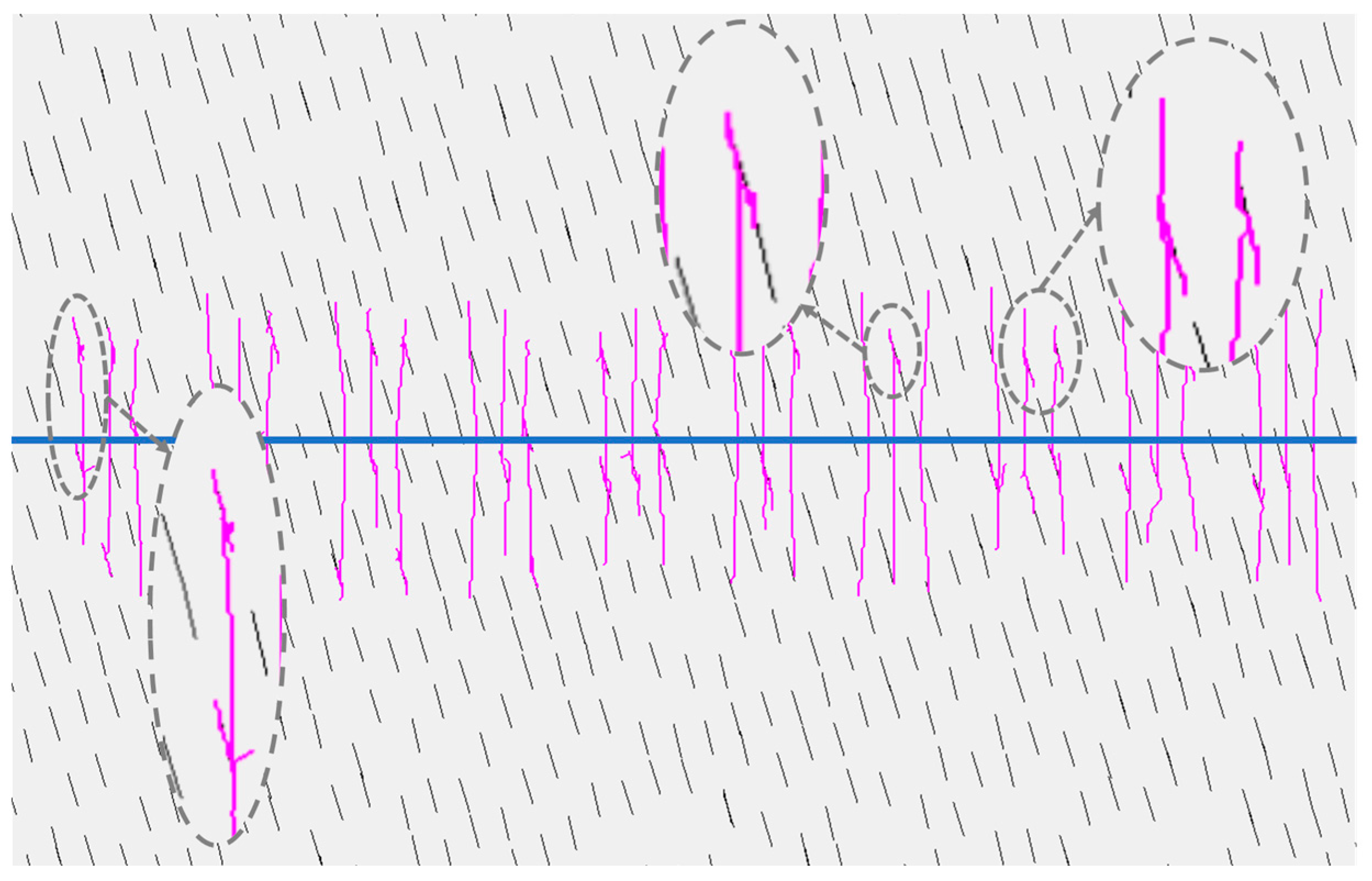
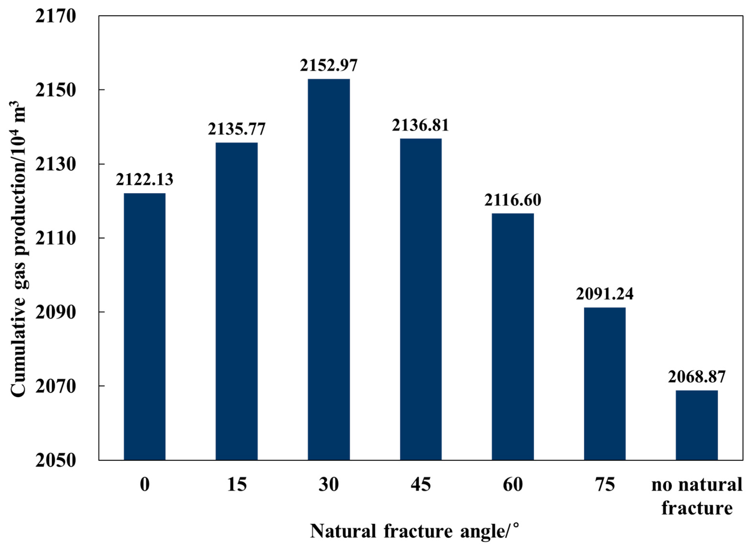
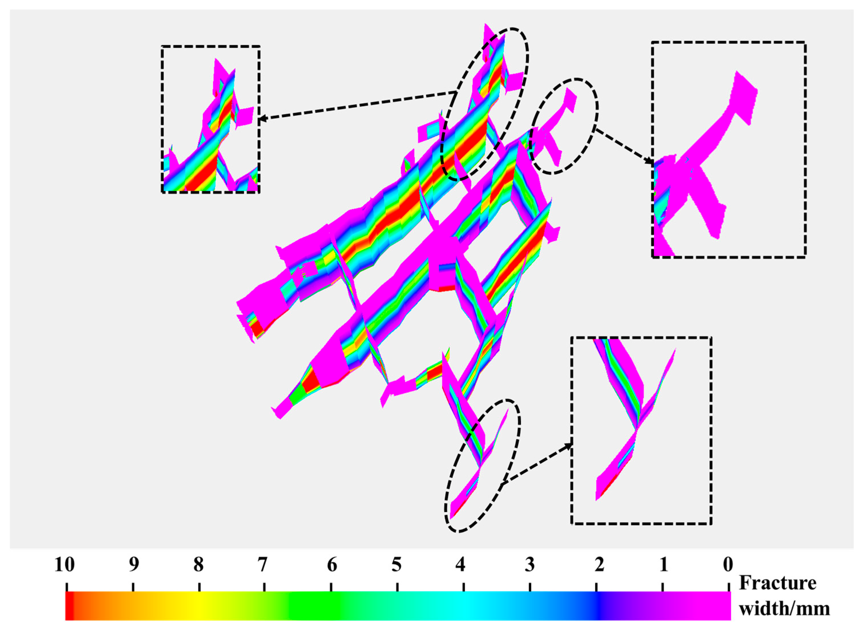
3.1. Natural Fracture Angle

The natural fracture angle influences the propagation path of hydraulic fractures. Based on the naturally fractured reservoir horizontal well's segmented multi-cluster fracturing simulation model established in Section 2.1, this section analyzed the interaction and propagation morphology of hydraulic fractures with natural fractures under six groups of natural fracture angles (0°, 15°, 30°, 45°, 60°, and 75°), the post-fracturing productivity of horizontal wells, and the pore pressure distribution around the fractures. Figure 3 illustrates the interaction and propagation morphology of hydraulic fractures with natural fractures at different natural fracture angles. In the figure, the blue horizontal lines represent the horizontal wellbore, and the pink lines represent the fracture propagation network. It can be observed in the figure that when natural fractures are well-developed in the reservoir, the primary hydraulic fracture activates and connects with the natural fractures to form a complex fracture network. When the natural fracture angles are relatively low (0°, 15°, 30°, and 45°), more natural fractures are activated, and the fracture network formed after the primary hydraulic fracture connects with the natural fractures is more complex. Conversely, at higher natural fracture angles (60° and 75°), only a few natural fractures are activated, and a complex fracture network is barely formed. Low-angle natural fractures are more likely to block the primary hydraulic fracture and are subsequently activated to propagate, resulting in shorter primary hydraulic fracture lengths under low-angle natural fractures. On the other hand, primary hydraulic fractures tend to penetrate high-angle natural fractures, leading to longer primary hydraulic fracture lengths under high-angle natural fractures. At any angle, the propagation direction of the primary hydraulic fracture that does not encounter natural fractures remains aligned with the direction of maximum horizontal principal stress.
Taking low-angle fractures with an angle of 0° as an example, Figure 4 provides an enlarged view of the interaction and propagation morphology of hydraulic fractures with natural fractures when the natural fracture angle is 0°. In the figure, the blue horizontal lines represent the horizontal wellbore, the black short lines indicate unstimulated natural fractures, and the pink lines represent the fracture propagation network. In Figure 4a,b, it can be observed that the primary hydraulic fracture intersects with the natural fractures while propagating along the direction of the maximum horizontal principal stress, partially or completely activating the natural fractures to continue extending toward their tips. Once activated, the ends of the natural fractures may reinitiate, forming secondary hydraulic fractures that propagate along the direction of the maximum principal stress. As shown in Figure 4c–e, under the influence of the induced stress field, secondary hydraulic fractures may be attracted to the primary hydraulic fractures, while they may also repel each other. For high-angle fractures with an angle of 75° as an example, Figure 5 provides an enlarged view of the interaction and propagation morphology of hydraulic fractures with natural fractures when the natural fracture angle is 75°. In the figure, it can be seen that most primary hydraulic fractures directly penetrate the natural fractures and continuously extend along the direction of the maximum horizontal principal stress. Only a few natural fractures are activated and connected with the primary hydraulic fractures, resulting in a less complex fracture network. Once activated, the natural fractures may reinitiate and propagate as secondary hydraulic fractures, either extending parallel to the original direction or quickly reorienting toward the direction of maximum principal stress, intertwining with the pre-existing fractures.
Figure 6 shows the width distribution of the fracture network when the natural fracture angle is 0°. In the figure, it can be observed that laterally, the primary hydraulic fracture has a greater width near the wellbore, which gradually narrows with increasing distance from the wellbore. Vertically, the fracture width shows a trend of gradually narrowing from the middle toward both the upper and lower ends. The width of the primary hydraulic fracture before intersecting the natural fracture is greater than after it intersects, with a rapid decrease in width at the intersection point. The overall width of the stimulated natural fractures is less than that of the primary hydraulic fracture. As shown in Figure 3, Figure 4, Figure 5 and Figure 6, natural fractures with low angles in the reservoir are more conducive to the formation of complex fracture networks during hydraulic fracturing, which is consistent with previously published experimental [8] and numerical results [25]. Furthermore, our study observed that the fracture width decreases after the hydraulic fracture crosses a natural fracture, which may have a potential impact on the transport and placement of proppants.
Figure 7 shows the four years of cumulative gas production of a single well under different natural fracture angles. In the figure, it can be seen that when the natural fracture angle is 75°, the four-year cumulative gas production of a single well is the lowest, at 2091.24 × 104 m3. Under the same parameters, the four-year cumulative gas production of a single well without natural fractures is 2068.87 × 104 m3, indicating that the presence of natural fractures positively impacts single well production. The four-year cumulative gas production of a single well initially increases and then decreases with the increasing angle of natural fractures. Under high-angle natural fractures, the cumulative gas production of a single well is generally lower than that under low-angle fractures. The maximum cumulative gas production of 2152.97 × 104 m3 is achieved when the natural fracture angle is 30°. This may be because, although the main fracture length is longer at high angles, a complex fracture network is not formed, resulting in a poorer overall reservoir stimulation effect. Conversely, when the natural fracture angle is too low, a complex fracture network can form, but the main fracture length is relatively short, leading to suboptimal production enhancement.
The distribution of pore pressure around the fractures at different post-production years when the natural fracture angle is 0° is shown in Figure 8. In the figure, it can be observed that after production starts, an elliptical pressure drop region forms around the fractures. The longer the production time, the lower the pore pressure and the larger the pressure drop area. For shorter production times, the pore pressure around the fracture network decreases non-uniformly. As shown in Figure 8 (1 year and 2 years), areas with a complex and dense fracture network, represented by pink regions, exhibit lower surrounding pore pressures, while areas with sparse fracture networks, represented by blue regions, experience a slower decrease in pore pressure. As shown in Figure 8 (3 years), at the tips of the fracture propagation at the heel and toe of the horizontal well, even though the hydraulic and natural fractures are intricately intertwined, the surrounding pore pressure drops slowly due to easier replenishment of energy from distant formations. After four years of production, substantial energy consumption in the formation leads to a more uniform change in pore pressure around the fracture network. In summary, it can be observed that the activation of natural fractures enhances the range and magnitude of pressure drop in localized areas of the reservoir. Under complex fracture morphologies, the surrounding reservoir is more thoroughly exploited.

3.2. Natural Fracture Density

The density of natural fractures has a significant impact on reservoir stimulation effectiveness. Based on the simulation model established in Section 2.1, this section simulated the interaction and propagation morphology of hydraulic fractures with natural fractures, the post-fracturing productivity of horizontal wells, and the pore pressure distribution around the fractures for six sets of natural fracture spacings (20 m, 25 m, 30 m, 35 m, 40 m, and 45 m) at natural fracture angles of 30° and 60°, respectively. Figure 9 and Figure 10 show the interaction and propagation morphology of hydraulic fractures with low-angle (30°) and high-angle (60°) natural fractures under different natural fracture spacings. Comparing the two figures, it can be seen that at any spacing, natural fractures are activated and connected with the primary hydraulic fractures to form a fracture network. When the natural fracture angle is 30°, primary hydraulic fractures are easily blocked by natural fractures, which then get activated. The smaller the natural fracture spacing, the greater the number of stimulated natural fractures, resulting in a higher number of secondary hydraulic fractures and less energy available for the extension of primary hydraulic fractures, leading to shorter primary hydraulic fracture lengths. When the natural fracture angle is 60°, a similar trend is observed where smaller natural fracture spacing results in more stimulated natural fractures and shorter primary hydraulic fracture lengths. However, in this case, hydraulic fractures more readily penetrate natural fractures, resulting in overall longer primary hydraulic fractures compared to when the natural fracture angle is 30°.
Overall, regardless of low or high angles, smaller natural fracture spacing (higher density) leads to a greater number of encounters and connections between hydraulic fractures and natural fractures, resulting in a more complex fracture network. When the natural fracture density is the same, the fracture network formed by the interaction of hydraulic fractures with natural fractures at low angles is more complex than that at high angles. This is characterized by shorter primary hydraulic fractures, a higher number of stimulated natural fractures, and more developed secondary hydraulic fractures.
Figure 11 shows an enlarged view of the interaction and propagation morphology of hydraulic fractures and low-angle (30°) natural fractures when the natural fracture spacing is 45 m. In the figure, it can be seen that with a natural fracture spacing of 45 m, the natural fracture density is relatively low, resulting in fewer instances where primary hydraulic fractures encounter and activate natural fractures. Hydraulic fractures that do not encounter natural fractures extend continuously in the direction of maximum horizontal principal stress, resulting in longer primary hydraulic fractures and a simpler fracture network structure. Figure 12 provides an enlarged view of the interaction and propagation morphology of hydraulic fractures and low-angle (30°) natural fractures when the natural fracture spacing is 20 m. In the figure, it can be seen that with a natural fracture spacing of 20 m, the natural fracture density is higher, leading to a significant increase in the number of stimulated natural fractures. The resulting secondary hydraulic fractures intertwine with the stimulated natural fractures and primary hydraulic fractures, forming a more complex fracture network and enhancing the reservoir stimulation effect. The interaction morphologies between hydraulic fractures and natural fractures vary at different locations. For natural fractures near the wellbore, primary hydraulic fractures extend and intersect with these natural fractures, activating and penetrating them to continue propagating. The stimulated natural fractures begin to propagate toward their tips at the intersection points with hydraulic fractures. Once fully activated, secondary hydraulic fractures form at the tips of the natural fractures and continue propagating in the direction of maximum horizontal principal stress. For natural fractures further from the wellbore, the energy within the hydraulic fractures significantly decreases, making them more likely to be blocked by natural fractures and extend along the natural fracture trajectory toward their tips. Once the natural fractures are fully opened, secondary hydraulic fractures form at their tips and continue propagating along the original direction. When stimulated natural fractures are in close proximity, they may attract and connect with each other. The secondary hydraulic fractures formed at the tips of the natural fractures may also connect and propagate under the influence of stress.
Figure 13 illustrates the width distribution of the fracture network in the first segment depicted in Figure 12. In the figure, it is evident that the width of the primary hydraulic fractures is significantly greater than that of the secondary hydraulic fractures. Although the natural fractures farther from the wellbore are activated and generate secondary hydraulic fractures, the limited energy within these fractures results in either a zero width at the tips of the secondary hydraulic fractures or the overall closure of the fractures, resulting in a width of zero. As shown in Figure 9, Figure 10, Figure 11, Figure 12 and Figure 13, selecting areas with well-developed low-angle natural fractures in the reservoir is favorable for the formation of large-scale complex fracture networks, which can effectively enhance the fracture stimulation volume. In this case, the energy dissipation within the fracture occurs more rapidly, resulting in smaller fracture widths for the activated natural fractures. This may require the timely use of fine-sized proppants to support the fractures.
Figure 14 depicts the four years of cumulative gas production of a single well under different natural fracture spacings at angles of 30° and 60°. It is evident in the figure that regardless of whether the natural fractures are at high or low angles, smaller natural fracture spacings result in higher cumulative gas production over four years, indicating a positive correlation between cumulative well production and natural fracture density. Under any natural fracture density, the cumulative gas production from the well with a 30° angle of natural fractures is consistently higher than that with a 60° angle. This phenomenon may be attributed to the more complex fracture network and larger reservoir volume associated with low-angle natural fractures. For natural fracture angles of 30° and 60°, the extreme differences in cumulative gas production under different natural fracture spacings are 93.48 × 10⁴ m3 and 57.92 × 10⁴ m3, respectively. This underscores the more significant impact of natural fracture density on cumulative gas production in the case of low-angle fractures. At natural fracture spacings of 20 m and 45 m, the differences in cumulative gas production between high and low angles are 44.48 × 10⁴ m3 and 23.32 × 10⁴ m3, respectively, indicating that larger spacings (lower densities) of natural fractures reduce the impact of changing natural fracture angles on cumulative gas production. When the natural fracture spacing is 20 m and the angle is 30°, the maximum cumulative gas production reaches 2177.63 × 104 m3, highlighting the beneficial effect of densely developed low-angle natural fractures on increasing single-well production capacity.
Under different combinations of natural fracture angles and spacing, the distribution of pore pressure around the fractures at different post-production years is illustrated in Figure 15. In the figure, it is evident that regardless of the angle or density of natural fractures, the extent and range of pore pressure decline around the fracture network increase with production time. As shown in Figure 15 (30°, 30 m, 2 years; 60°, 30 m, 2 years), under the same natural fracture density after 2 years of production, the pore pressure is lower around the complex fracture network formed at low angles, whereas the fracture network formed at high angles is simpler, with lower pore pressure only around the middle section of the horizontal well segment, indicated by the pink area in the figure. Over longer production times, as depicted in Figure 15 (30°, 30 m, 3 years; 60°, 30 m, 3 years; 30°, 40 m, 3 years), significant reservoir energy consumption leads to an elliptical decline in pore pressure around the fracture network, with uniform pressure reduction near the wellbore and middle section of the horizontal well segment. However, at the root and toe sections of the wellbore near the fracture tips, there is a non-uniform variation in pore pressure. Overall, as the complexity of the fracture morphology increases, areas between fracture clusters that were previously not effectively producible show a significant increase in pressure drop, leading to an expanded exploitation range and accelerated production progress in the reservoir.

3.3. Natural Fracture Length

To investigate the impact of the natural fracture length on the competitive propagation of multiple fractures and post-fracturing productivity in horizontal wells, this section utilized the simulation model established in Section 2.1. Twelve different combinations of natural fracture angles, densities, and lengths were simulated to analyze the interaction and propagation morphology of hydraulic fractures with natural fractures and the variation in post-fracturing productivity of horizontal wells. Table 2 lists the 12 different combinations of natural fracture angles, densities, and lengths.
Figure 16 shows the interaction and propagation morphology of hydraulic fractures with low-angle (30°) natural fractures under different combinations of natural fracture lengths and spacings. In the figure, it is observed that primary hydraulic fractures activate natural fractures during their propagation, generating secondary hydraulic fractures that interweave to form a fracture network. As natural fractures become longer and spacings smaller, the resulting fracture network becomes more complex. At low angles, whether the natural fracture density is high or low, the propagation morphology of the fracture network exhibits similar characteristics. When natural fractures are shorter, the primary hydraulic fractures formed through interaction with natural fractures are longer, while the stimulated natural fractures are shorter, resulting in a greater number of secondary hydraulic fractures. Figure 17 depicts the interaction and propagation morphology of hydraulic fractures with high-angle (60°) natural fractures under different combinations of natural fracture lengths and spacings. It is evident in the figure that at high angles, the fracture network formed through interaction with hydraulic fractures under similar lengths and spacings of natural fractures is structurally simpler compared to low-angle networks, with fewer hydraulic fractures activating natural fractures. Similar to the patterns observed at low angles, regardless of whether the natural fracture density is high or low, the propagation morphology of the fracture network shows that when natural fractures are longer, the primary hydraulic fractures formed through interaction with natural fractures are shorter, while the stimulated natural fractures are longer. Shorter natural fracture lengths and larger spacings result in a fracture network propagation morphology closer to that observed without natural fractures.
Using the example of low-angle natural fractures with a length of 20 m and a spacing of 25 m, as shown in Figure 18, the primary hydraulic fractures intersect and activate multiple natural fractures during their propagation. The stimulated natural fractures extend along their original direction toward both ends, with secondary hydraulic fractures forming at the tips. Influenced by the induced stress field, some secondary hydraulic fractures repel each other and expand in an X-shaped morphology at the tips of the stimulated natural fractures. At this stage, there are a relatively large number of stimulated natural fractures and secondary hydraulic fractures, but their lengths are shorter. When natural fractures are longer, the interaction between hydraulic fractures and natural fractures results in shorter primary hydraulic fractures and longer secondary hydraulic fractures. Taking low-angle natural fractures with a length of 50 m and a spacing of 25 m as an example, as shown in Figure 19, hydraulic fractures also encounter and activate natural fractures during their propagation. However, due to the limited energy available for fracture propagation, more energy is dissipated within the natural fractures. This energy dissipation in the natural fractures suppresses the development of secondary hydraulic fractures, significantly reducing the length of the primary hydraulic fractures. When there is sufficient energy, secondary hydraulic fractures can also activate natural fractures during their propagation. As shown in Figure 17, Figure 18 and Figure 19, when the length of natural fractures is larger, they exert a stronger blocking effect on hydraulic fractures, leading to the formation of more complex fracture networks in localized areas. However, this also limits the extension length of the main fracture.
The four years of cumulative gas production of a single well under different combinations of natural fracture length and density at angles of 30° and 60° is shown in Figure 20. In the figure, it can be observed that for any natural fracture angle and spacing, the longer the natural fractures, the greater the four years of cumulative gas production per well. This indicates a positive correlation between cumulative gas production and natural fracture length. The cumulative gas production trends for different fracture lengths consistently follow the following order: natural fracture spacing of 25 m and angle of 30° > natural fracture spacing of 25 m and angle of 60° > natural fracture spacing of 40 m and angle of 30° > natural fracture spacing of 40 m and angle of 60°. Overall, during the interaction and propagation of hydraulic fractures with high-density, low-angle long natural fractures, a complex fracture network can form, enhancing the reservoir stimulation effect and thus achieving higher productivity. When the combinations of natural fracture spacing and angle are 25 m, 30°; 40 m, 30°; 25 m, 60°; and 40 m, 60°, the ranges of cumulative gas production per well for different natural fracture lengths are 38.93 × 10⁴ m3, 33.53 × 10⁴ m3, 27.87 × 10⁴ m3, and 20.78 × 10⁴ m3, respectively. This indicates that the smaller the natural fracture spacing at low angles, the more significant the impact of the natural fracture length on the cumulative gas production per well. The maximum cumulative gas production of 2192.59 × 104 m3 is achieved when the natural fracture length is 50 m, the spacing is 25 m, and the angle is 30°. Therefore, placing fractures in areas with long, low-angle, high-density natural fractures significantly enhances single-well productivity.

4. Conclusions

A segmented multi-cluster fracturing simulation model for natural fractured reservoirs was developed, considering the characteristics of fractured tight sandstone in the area. This model was used to simulate the interaction and propagation of hydraulic fractures with natural fractures at varying angles, densities, and lengths, as well as to assess post-fracturing well productivity and pore pressure distribution around fractures. The main findings are as follows:
  • Secondary hydraulic fractures are repelled by each other and attracted to primary fractures due to induced stress. They may propagate parallel to or rapidly intertwine with primary fractures along the direction of maximum principal stress. The pore pressure decreases more sharply where hydraulic fractures intersect natural fractures.
  • When natural fractures have smaller angles, more fractures are activated, secondary hydraulic fractures extend more extensively, and primary fractures are shorter, leading to a more complex fracture network. Higher natural fracture angles result in hydraulic fractures penetrating natural fractures, simplifying the fracture network.
  • Higher natural fracture densities and longer lengths lead to more hydraulic fractures intersecting natural fractures, longer stimulated natural fractures, and a more complex fracture network. Lower-angle natural fractures significantly affect network complexity compared to higher-angle fractures in terms of both density and length.
  • The cumulative gas production per well increases initially and then decreases with increasing natural fracture angles but increases with higher natural fracture densities and lengths. Lower-angle fractures yield higher cumulative gas production compared to higher-angle fractures.
  • For lower natural fracture angles, smaller fracture spacings have a more significant impact on cumulative gas production per well. Optimal well productivity is achieved in areas with longer natural fractures, lower angles, and higher fracture densities.

Author Contributions

Conceptualization, T.G. and X.Y.; methodology, L.Z. and H.W.; software, Y.J. and X.Y.; validation, X.S. and Y.W.; formal analysis, X.S. and Y.J.; investigation, L.Z. and Y.J.; resources, T.G.; data curation, Y.W.; writing—original draft preparation, H.W.; writing—review and editing, D.Z. and X.Y.; visualization, X.Y.; supervision, T.G.; project administration, L.Z.; funding acquisition, D.Z. and H.W. All authors have read and agreed to the published version of the manuscript.

Funding

This research was funded by the National Natural Science Foundation of China, grant number U23B2089, and the Shaanxi Provincial Natural Science Basic Research Program Project, grant number 2024JC-YBQN-0554.

Data Availability Statement

The data presented in this study are available upon request from the corresponding author: wanghaiyang@xsyu.edu.cn.

Conflicts of Interest

Author Tuan Gu, Xiang Yu and Linpeng Zhang were employed by the company Exploration and Development Research Institute of Liaohe Oilfield Company, Petro China. Author Yenan Jie was employed by the company Shaanxi Yanchang Petroleum (Group) Co., Ltd., Natural Gas Research Institute Branch. The remaining authors declare that the research was conducted in the absence of any commercial or financial relationships that could be construed as a potential conflict of interest. The authors declare that this study received no funding form Exploration and Development Research Institute of Liaohe Oilfield Company, Petro China and Shaanxi Yanchang Petroleum (Group) Co., Ltd., Natural Gas Research Institute Branch.

Nomenclature

ETEffective thickness [m]
PoReservoir pressure [MPa]
φPorosity [%]
PmPermeability [mD]
GSGas saturation [%]
SHMaximum horizontal principal stress [MPa]
ShMinimum horizontal principal stress [MPa]
SvOverburden pressure [MPa]
TTemperature [°C]
EYoung’s modulus [GPa]
νPoisson’s ratio
KICFracture toughness [kPa∙m0.5]
MDMeasure depth [m]
TVDTrue Vertical Depth [m]
LHorizontal section length [m]
FSFracturing stages.
NCNumber of fracture clusters.
CSCluster spacing [m]
NlNatural fracture length [m]
NsNatural fracture spacing [m]
NaNatural fracture angle [°]

References

  1. Jia, C. Prospects and five future theoretical and technical challenges of the upstream petroleum industry in China. Acta Pet. Sin. 2024, 45, 1–14. [Google Scholar] [CrossRef]
  2. Xie, Q.; Li, J.; Ye, X.; Gao, J.; Song, Y.; Hu, S. Analysis of Water Production Factors of Gas Wells in Sulige Gas Field. J. Phys. Conf. Ser. 2024, 2860, 012023. [Google Scholar] [CrossRef]
  3. Carson, S.A. Independent and major equity market and commodity return sources around the time of hydraulic fracking and horizontal drilling revolution: A differences-in-decompositions approach. Econ. Innov. New Technol. 2024, 33, 26–44. [Google Scholar] [CrossRef]
  4. Ismail, A.; Azadbakht, S. A comprehensive review of numerical simulation methods for hydraulic fracturing. Int. J. Numer. Anal. Methods Geomech. 2024, 48, 1433–1459. [Google Scholar] [CrossRef]
  5. Fu, W.; Ames, B.C.; Bunger, A.P.; Savitski, A.A. Impact of Partially Cemented and Non-persistent Natural Fractures on Hydraulic Fracture Propagation. Rock Mech. Rock Eng. 2016, 49, 4519–4526. [Google Scholar] [CrossRef]
  6. Wen, Q.; Wang, S.; Duan, X.; Li, Y.; Wang, F.; Jin, X. Experimental investigation of proppant settling in complex hydraulic-natural fracture system in shale reservoirs. J. Nat. Gas Sci. Eng. 2016, 33, 70–80. [Google Scholar] [CrossRef]
  7. Fatahi, H.; Hossain, M.M.; Sarmadivaleh, M. Numerical and experimental investigation of the interaction of natural and propagated hydraulic fracture. J. Nat. Gas Sci. Eng. 2017, 37, 409–424. [Google Scholar] [CrossRef]
  8. Wan, L.; Chen, M.; Hou, B.; Kao, J.; Zhang, K.; Fu, W. Experimental investigation of the effect of natural fracture size on hydraulic fracture propagation in 3D. J. Struct. Geol. 2018, 116, 1–11. [Google Scholar] [CrossRef]
  9. Yildirim, B.; Durucan, S.; Cao, W.; Cai, W.; Shi, J.; Korre, A.; Wolf, K.H. Experimental and Numerical Investigation into Hydraulic Fracture and Natural Fracture Interaction in Shale Formations. In Proceedings of the 53rd U.S. Rock Mechanics/Geomechanics Symposium, New York, NY, USA, 23–26 June 2019; p. ARMA–2019-0437. [Google Scholar]
  10. Gale, J.; Elliott, S.; Li, J.Z.; Laubach, S. Natural Fracture Characterization in the Wolfcamp Formation at the Hydraulic Fracture Test Site (HFTS), Midland Basin, Texas. In Proceedings of the SPE/AAPG/SEG Unconventional Resources Technology Conference, Denver, CO, USA, 22–24 July 2019; p. D023S039R001. [Google Scholar]
  11. Dehghan, A.N. An experimental investigation into the influence of pre-existing natural fracture on the behavior and length of propagating hydraulic fracture. Eng. Fract. Mech. 2020, 240, 107330. [Google Scholar] [CrossRef]
  12. Liu, Y.; Zheng, X.; Peng, X.; Zhang, Y.; Chen, H.; He, J. Influence of natural fractures on propagation of hydraulic fractures in tight reservoirs during hydraulic fracturing. Mar. Pet. Geol. 2022, 138, 105505. [Google Scholar] [CrossRef]
  13. Zhang, Y.; Long, A.; Zhao, Y.; Zang, A.; Wang, C. Mutual impact of true triaxial stress, borehole orientation and bedding inclination on laboratory hydraulic fracturing of Lushan shale. J. Rock Mech. Geotech. Eng. 2023, 15, 3131–3147. [Google Scholar] [CrossRef]
  14. Gonzalez, M.; Taleghani, A.D.; Olson, J.E. A Cohesive Model for Modeling Hydraulic Fractures in Naturally Fractured Formations. In Proceedings of the SPE Hydraulic Fracturing Technology Conference, Woodlands, TX, USA, 3–5 February 2015; p. D031S007R002. [Google Scholar]
  15. Guo, J.; Zhao, X.; Zhu, H.; Zhang, X.; Pan, R. Numerical simulation of interaction of hydraulic fracture and natural fracture based on the cohesive zone finite element method. J. Nat. Gas Sci. Eng. 2015, 25, 180–188. [Google Scholar] [CrossRef]
  16. Wu, K.; Olson, J.E. Numerical Investigation of Complex Hydraulic-Fracture Development in Naturally Fractured Reservoirs. SPE Prod. Oper. 2016, 31, 300–309. [Google Scholar] [CrossRef]
  17. Chong, Z.; Li, X.; Chen, X.; Zhang, J.; Lu, J. Numerical Investigation into the Effect of Natural Fracture Density on Hydraulic Fracture Network Propagation. Energies 2017, 10, 914. [Google Scholar] [CrossRef]
  18. Chen, Z.; Jeffrey, R.G.; Zhang, X.; Kear, J. Finite-Element Simulation of a Hydraulic Fracture Interacting With a Natural Fracture. SPE J. 2016, 22, 219–234. [Google Scholar] [CrossRef]
  19. Dahi Taleghani, A.; Gonzalez-Chavez, M.; Yu, H.; Asala, H. Numerical simulation of hydraulic fracture propagation in naturally fractured formations using the cohesive zone model. J. Pet. Sci. Eng. 2018, 165, 42–57. [Google Scholar] [CrossRef]
  20. Shrivastava, K.; Agrawal, S.; Kumar, A.; Sharma, M.M. 3-D Interactions of Hydraulic Fractures with Natural Fractures. In Proceedings of the SPE International Hydraulic Fracturing Technology Conference and Exhibition, Muscat, Oman, 16–18 October 2018; p. D023S018R001. [Google Scholar]
  21. Li, Z.-Q.; Li, X.-L.; Yu, J.-B.; Cao, W.-D.; Liu, Z.-F.; Wang, M.; Liu, Z.-F.; Wang, X.-H. Influence of existing natural fractures and beddings on the formation of fracture network during hydraulic fracturing based on the extended finite element method. Geomech. Geophys. Geo-Energy Geo-Resour. 2020, 6, 58. [Google Scholar] [CrossRef]
  22. Zhao, H.; Li, W.; Wang, L.; Fu, J.; Xue, Y.L.; Zhu, J.J.; Li, S.Q. The Influence of the Distribution Characteristics of Complex Natural Fracture on the Hydraulic Fracture Propagation Morphology. Front. Earth Sci. 2022, 9, 784931. [Google Scholar] [CrossRef]
  23. Dong, Y.; Tian, W.; Li, P.; Zeng, B.; Lu, D. Numerical investigation of complex hydraulic fracture network in naturally fractured reservoirs based on the XFEM. J. Nat. Gas Sci. Eng. 2021, 96, 104272. [Google Scholar] [CrossRef]
  24. Xiong, D.; Ma, X. Influence of natural fractures on hydraulic fracture propagation behaviour. Eng. Fract. Mech. 2022, 276, 108932. [Google Scholar] [CrossRef]
  25. Hu, Y.; Gan, Q.; Hurst, A.; Elsworth, D. Investigation of coupled hydro-mechanical modelling of hydraulic fracture propagation and interaction with natural fractures. Int. J. Rock Mech. Min. Sci. 2023, 169, 105418. [Google Scholar] [CrossRef]
  26. Wang, H.; Yang, S.; Zhou, D.; Wang, Q. Influence of non-intersecting cemented natural fractures on hydraulic fracture propagation behavior. J. Struct. Geol. 2024, 181, 105111. [Google Scholar] [CrossRef]
  27. Schlumberger. Petrel E&P Software Platform, 2024; Schlumberger: Houston, TX, USA, 2009. [Google Scholar]
  28. Wang, H.; Zhou, D. Mechanistic study on the effect of seepage force on hydraulic fracture initiation. Fatigue Fract. Eng. Mater. Struct. 2024, 47, 1602–1619. [Google Scholar] [CrossRef]
  29. Valkó, P.P.; Lee, W.J. A Better Way to Forecast Production from Unconventional Gas Wells. In Proceedings of the SPE Annual Technical Conference and Exhibition, Florence, Italy, 20–22 September 2010; p. SPE–134231-MS. [Google Scholar]
Figure 1. The segmented multi-cluster fracturing simulation model for horizontal well (Well J, where the natural fracture angle is 0°, spacing is 30 m, and length is 30 m). (a) The 2D hydraulic fracture propagation morphology; (b) 3D hydraulic fracture propagation morphology; (c) partially enlarged view of crack morphology.
Processes 12 02813 g001
Figure 2. History fitting curve of Well J.
Processes 12 02813 g002
Figure 3. Interaction and propagation morphology of hydraulic fractures with natural fractures at different natural fracture angles.
Processes 12 02813 g003
Figure 4. Enlarged image of interactive propagation morphology of hydraulic fractures and natural fractures when the natural fracture angle is 0°. (a,b): The primary hydraulic fracture intersects with the natural fracture; (ce): The secondary hydraulic fractures are attracted by the primary hydraulic fractures.
Processes 12 02813 g004
Figure 5. Enlarged image of interactive propagation morphology of hydraulic fractures and natural fractures when the natural fracture angle is 75°.
Processes 12 02813 g005
Figure 6. Width distribution of the fracture network when the natural fracture angle is 0°.
Processes 12 02813 g006
Figure 7. Four years of cumulative gas production of a single well under different natural fracture angles.
Processes 12 02813 g007
Figure 8. Distribution of pore pressure around the fractures at different post-production years when the natural fracture angle is 0°.
Processes 12 02813 g008
Figure 9. Interaction and propagation morphology of hydraulic fractures with low-angle (30°) natural fractures under different natural fracture spacings.
Processes 12 02813 g009
Figure 10. Interaction and propagation morphology of hydraulic fractures with high-angle (60°) natural fractures under different natural fracture spacings.
Processes 12 02813 g010
Figure 11. Enlarged view of the interaction and propagation morphology of hydraulic fractures and low-angle (30°) natural fractures when the natural fracture spacing is 45 m.
Processes 12 02813 g011
Figure 12. Enlarged view of the interaction and propagation morphology of hydraulic fractures and low-angle (30°) natural fractures when the natural fracture spacing is 20 m.
Processes 12 02813 g012
Figure 13. Width distribution of the fracture network in the first segment depicted in Figure 12.
Processes 12 02813 g013
Figure 14. Four-year cumulative gas production of a single well under different natural fracture spacings at angles of 30° and 60°.
Processes 12 02813 g014
Figure 15. Distribution of pore pressure around the fractures at different post-production years under different natural fracture angles and spacing combinations.
Processes 12 02813 g015
Figure 16. Interaction and propagation morphology of hydraulic fractures with low-angle (30°) natural fractures under different combinations of natural fracture lengths and spacings.
Processes 12 02813 g016
Figure 17. Interaction and propagation morphology of hydraulic fractures with high-angle (60°) natural fractures under different combinations of natural fracture lengths and spacings.
Processes 12 02813 g017
Figure 18. Enlarged view of the interaction and propagation morphology of hydraulic fractures and low-angle (30°) and high-density (25 m) natural fractures when the natural fracture length is 20 m.
Processes 12 02813 g018
Figure 19. Enlarged view of the interaction and propagation morphology of hydraulic fractures and low-angle (30°) and high-density (25 m) natural fractures when the natural fracture length is 50 m.
Processes 12 02813 g019
Figure 20. Four years of cumulative gas production of a single well under different combinations of natural fracture length and density at angles of 30° and 60°.
Processes 12 02813 g020
Table 1. Basic parameters of the model.
Reservoir physical parametersEffective thickness, ET/m17.6
Reservoir pressure, Po/MPa32
Porosity, φ/%9.1
Permeability, Pm/mD0.28
Gas saturation, GS/%64
Maximum horizontal principal stress, SH/MPa47
Minimum horizontal principal stress, Sh/MPa44
Overburden pressure, Sv/MPa78
Temperature, T/°C92
Rock mechanical parametersYoung’s modulus, E/GPa40
Poisson’s ratio, ν0.2
Fracture toughness, KIC/kPa∙m0.51319
Wellbore parametersMD/m4800
TVD/m3274
Horizontal section length, L/m1200
Fracturing stages, FS9
Number of fracture clusters, NC3
Cluster spacing, CS/m15
Table 2. The 12 different combinations of natural fracture angles, densities, and lengths.
SchemeNatural Fracture Length, Nl/mNatural Fracture Spacing, Ns/mNatural Fracture Angle, NaSchemeNatural Fracture Length, Nl/mNatural Fracture Spacing, Ns/mNatural Fracture Angle, Na
12025307202560
23025308302560
35025309502560
420403010204060
530403011304060
650403012504060
Disclaimer/Publisher’s Note: The statements, opinions and data contained in all publications are solely those of the individual author(s) and contributor(s) and not of MDPI and/or the editor(s). MDPI and/or the editor(s) disclaim responsibility for any injury to people or property resulting from any ideas, methods, instructions or products referred to in the content.

