Abstract
The main purpose of this paper was to study the vertical settlement of offshore wind turbine (OWT) monopile support structures, where 5, 10, 15, and 20 MW OWT support structures were analyzed under power production, seismic, and tropical cyclone loads. Moreover, a t-z spring with shear and torsional degrees of freedom was developed to simulate the shear stress along the pile and soil surface under the combined effect of vertical loads and z-direction torsions. This t-z spring does not require excessive changes to the finite element program, where only a known factor is used to modify the traditional stiffness of the t-z spring. This paper, analyzing several kinds of OWT monopile foundations, indicates that the soil shear resistance may be less than the shear stress generated by the combination of vertical loads and torsions, which causes large vertical and rotational displacements resulting in the failure of monopile structures. This situation will be worse when the natural frequency of the first vertical-direction rotation is close to the integer multiples of the 3P frequency, which cannot be well-simulated using traditional t-z springs.
1. Introduction
Offshore wind turbine (OWT) foundations are mostly constructed using monopile and jacket types. Based on the seawater depth, manufacturing complexity, and fatigue problem, monopile foundations are still mainstream (73.5%) in shallow or medium-depth water. Recently, large-scale OWTs with monopile foundations have been gradually invested, where the vertical settlement of the pile has attracted the attention of researchers in recent years, especially when the soil of the seabed is not strong enough. Yu et al. [1] performed earthquake centrifuge experiments on monopile foundations. The earthquake-induced soil liquefaction experiments showed that stone columns, densification, and cementation techniques were effective in reducing earthquake-induced settlement. Anastasopoulos and Theofilou [2] studied a hybrid OWT monopile foundation and indicated that although seismic shaking is not critical in terms of capacity, it may lead to a substantial accumulation of rotation and settlement. Kaynia [3] pointed out that OWT support structures, often with rather high vertical natural frequencies, are particularly susceptible to vertical seismic excitations. In addition, soil nonlinearity can lead to settlement and permanent tilting of OWTs on permanent caisson foundations or tripods. Wang et al. [4] used the centrifuge test results to show that monopile foundations can effectively reduce lateral displacement during shaking but may cause more pile settlement due to the large shear stress along the pile. Wang et al. [5] studied the seismic response and liquefaction characteristics of the monopile foundation and indicated that OWTs with monopile foundations tend to settle more during seismic dynamic loads than by static bearing. Staubach et al. [6] presented a parametric study on the deformations of OWT monopile foundations using finite element analyses and found that the pile settlement increased with a growing number of cycles and reached values up to approximately 40 cm in the simulation with loose soil. Shi et al. [7] used a sophisticated 3D finite element model of an NREL 5 MW OWT support structure with nonlinear p-y, t-z, and Q-z springs for the soil–structure interaction (SSI) effect, and they found that SSI is important for the finite element result.
Although a lot of studies have presented the critical situation of OWT structural settlements under dynamic loads, there are not many investigations on the mechanics of OWT foundation vertical settlement, which is mainly due to the self-weight and torsion from rotor blades under turbulent winds. The torsional load applied to a group of piles will change the soil lateral normal reaction of each pile. However, for a tubular monopile foundation, the torsional load can only provide support through the soil shear force along the pile surface. For this reason, the shear force from the combination of the self-weight and torsion cannot be avoided, and it can be even worse because the soil's ultimate shear capacity is much smaller than the soil's ultimate lateral normal capacity. Several relative studies are discussed below. Basack and Sen [8] proposed a boundary element method to analyze the response of a monopile subjected to simultaneous torsional and axial loads, while they found that combined torsional and axial loads will not only induce twisting at the pile head but also reduce its axial capacity significantly with the increased settlement of the foundation. Hamed et al. [9] investigated the vibration control, stability, and energy transfer of the OWT tower system with control force and nonlinearity terms, and the results showed the effectiveness of the NPD controller in suppressing the nonlinear oscillations of the wind turbine system. Nimbalkar et al. [10] proposed a boundary element method to study the single pile under torsional cyclic loading, and the results showed that the frequency, amplitude, and number of cycles play important roles in the torsional cyclic response of the pile. Jiang et al. [11] studied the bearing characteristics of a single pile under the combined torque and vertical load on the pile top. The results showed that the vertical bearing capacity decreases with the increase in the torque on a single pile, and the combined effect becomes more obvious when the torque load exceeds one-third of the limit value. Mehra and Trivedi [12] proposed a computational procedure to evaluate the effects of combined axial and torsional loads in flow-controlled geomaterials. It was observed that the settlement displacement increased significantly with the torsional load for the large-diameter pile and pile groups. Altan and Gungor [13] examined the performance of wind dual turbines rotating opposite each other. An optimal triangular plate was placed in front of the turbines to reduce the torsion on the structure. Al-Quraan et al. [14] proposed a method to identify the optimal spacing between arrays. The results showed the optimal spacing is reduced by around 16% from the actual spacing. Radaideh et al. [15] proposed a linear quadratic regulator (LQR) with optimal gain-scheduling for wind turbines, and the LQR controller has the chance to reduce the forces generated from the rotor blades.
In the literature, several references investigated the pile settlement due to axial and torsional loads, but few studies directly focused on OWT monopile foundations. Therefore, in this research, a t-z spring with both shear and torsional effects was developed to study the settlement of large-scale OWT support structures, and its formula and simulation results were discussed in detail.
2. Finite Element Formulation of a T-Z Spring with Torsion and Shear Effects
2.1. Formulations
In this section, although other consistent units can still be used, we provide the SI units (kN and m) of the variables in the equations to show them clearly. As shown in Figure 1, a tubular pile segment with a radius of R (m) and a section length of (m) is subjected to torsion T (kN-m) and shear stress t (kN/m2) in the axial direction of the pile, where z (m) and θ (rad) are the displacement and twist angle of the t-z curve spring (the difference between the two nodes of the spring). Thus, the total displacement (d (m)) and the total shear stress due to the shear force and torsion are:
where (m3), and (kN/m2).
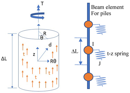
Figure 1.
The t-z curve finite element, including the shear and torsional effects.
From Equations (1) and (2), the stiffness matrix is obtained as follows:
D is the pile diameter (m) (D = 2R), is the element segment interval (m), is the incremental force of the t-z spring (kN), , and . Equation (4) shows the components of the stiffness matrix of the shear and torsional t-z curve elements, where is the traditional t-z curve stiffness considering only the shear stress. Any t-z curve formulation can be used for , and we use a cyclic formulation to validate them in the next section. In Equation (4), if the torsion T and the twist angle are equal to zero, then we set and to generate the standard t-z curve stiffness for the degree of freedom of the shear force.
To simplify the formulation in the finite element analysis, one can assume that the stresses (t and s) are proportional to the shear and torsional displacements (z and ) so that Equation (4) becomes (kN/rad) and (kN/m3). Another important issue is that convergence difficulties may occur when the torsional stress is small since such small stresses may oscillate between positive and negative values. To overcome this, an empirical scheme can be used to set zero torsional stress when this occurs. As shown in Figure 1, the finite element model of this t-z spring has two nodes, such as I and J in Figure 1, where node I is located at the node of the pile simulated using the beam element, and node J is a different node. The coordinates of node J can be the same as those of node I, and the direction of the t-z spring is along the pile direction (local z-direction). Node J only contains two degrees of freedom, z-displacement and z-rotation. If there are no seismic motions, the two degrees of freedom should be fixed. Otherwise, the z-rotation degree of freedom is fixed, and the z-displacement one is subjected to seismic motions. Equation (3) can be directly used to find the local stiffness matrix of the t-z spring, and a transformation is used to find the global stiffness matrix, which can be added to the total global stiffness matrix. The internal forces can be obtained using Equation (3) again when the incremental displacements are solved. Since . is the traditional nonlinear stress–displacement relationship, a nonlinear iteration solver, such as the Newton–Raphson method, should be used to solve the total global matrix equation. The Fortran source codes ntzcyc.for (in the compressed executable file anp.exe located at the directory windturb\exe) of the proposed t-z spring and the OWT structural analysis program can be found on the website (Item 16 of https://sites.google.com/view/jushenhaw (accessed on 31 January 2023)).
2.2. Validation Examples
Several spring models can be used to predict the interaction between piles and soil. Among them, the models developed by Boulanger et al. [16], including nonlinear p-y, q-z, and t-z springs, have been widely used, so they were used to perform the validation analyses. Since, in this study, the t-z spring is modified, including the torsional effect, we only focused on the formulation of the t-z spring, and the p-y and q-z spring models can be referred to in the above references, although we also used them to perform the optimal design for the 10 MW DTU OWT [17,18] support structure in the next section. The soil t-z spring can be modeled as an elastic–plastic curve, where the initial linear elastic range of the elastic–plastic spring is between < . < , where (kN/m2) is the total shear stress along the pile surface of the t-z element, (kN/m2) is the ultimate resistance of the t-z element in the current loading direction, and Cr is the ratio of when plastic yielding first occurs in the first original loading. The linear elastic range is between − and + with the Young’s modulus of Ce, where Ce is a constant. When the linear elastic range is exceeded, the equation of the elastic–plastic spring is described in the following nonlinear equation:
where d (m) is the total displacement of the t-z element, 0 is equal to at the beginning of the current plastic loading cycle, d0 is equal to d at the start of the current plastic loading cycle, c is the constant used to control the tangent modulus at the start of plastic yielding, n is the exponent used to control the sharpness of the t-z curve, and (m) is the shear displacement at the half of during monotonic loading.
Equation (5) can be used in conjunction with Equations (3) and (4) to obtain the stiffness of the t-z spring during plasticity so that the elastic–plastic t-z spring element can be developed in a nonlinear dynamic finite element program. In order to validate the torsional effect of the proposed t-z spring, a single elastic–plastic t-z spring is used to connect a pile with a diameter of 7.8 m, where one end is fixed, and the other is applied to the sine-shaped shear displacement (z = 0.04 sin(2t) m) and rotation ( = Bsin(2t) rad), in which B = 0 and 0.01 for two pile cases. The material properties of the t-z spring are = 0.35, = 100 kN/m2, Ce = 1.23, = 0.0043 m, and n = 0.85. These parameters were obtained from the curve fitting of the soil near Changhua Offshore in Taiwan, where the sixth layer of soil was used, as shown in Table 1. Both the finite element analysis (FEA) and the numerical solution of Equation (5) (Theory) were performed. The results are shown in Figure 2, where cases 1 and 2 are 0 and 0.01 for B, respectively. This figure provides a good comparison and indicates that the finite element analysis is accurate and feasible for the combination of shear and torsional effects.

Table 1.
Soil ultimate stresses of each soil layer (tult = the ultimate shear stress for the t-z curve, qult = the ultimate tip resistance for the Q-z curve, and pult = the ultimate earth resistance for the p-y curve.).
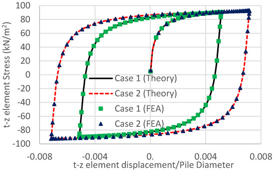
Figure 2.
Comparisons of the displacement–stress curves between the theoretical and finite element methods.
3. Study on Vertical Settlements of Monopile Wind Turbines
3.1. For DTU 10 MW OWT System
This section focuses on detailing the settlement analysis of the DTU 10 MW OWT system [15], and the next section will study 5, 15, and 20 MW OWT systems. The finite element mesh contains 50, 50, and 70 2-node beam elements for the tower, column, and pile, respectively. The p-y and t-z springs are then arranged at pile nodes, while a Q-z spring is set at the pile end. First, the structural analysis and steel design were performed to determine the optimal tubular sections of the OWT support structure, so the following settlement parameter study can be reasonable, while the procedure and loads are referred from the reference [19]. The design load cases (DLC), as shown in Table 2 of ref. [19], included (1) the loads of situations 1 to 7 in IEC 61400-3-1, (2) seismic loads (DLC 1.8 and 6.7 in IEC 61400-1) with the peak ground motion (PGA) of 0.32 g, and (3) tropical cyclones (DLC I.1 and I.2 in IEC 61400-3-1) under the average hub wind speed (Vhub) of 72 m/s, where the finite element analysis of the OWT support structure under seismic loads can be found in refs. [20,21]. Figure 3 shows the finite element model and the dimensions of the final design result with an average sea depth of 25 m. The soil is moderate–hard sandy soil with a submerged weight density (γ) of 9 kN/m3 and a submerged internal frictional angle (ψ) of 32°. The ultimate lateral resistance of this sandy soil for the p-y curve was then calculated using API [22] formulation, where only the pile diameter, γ, ψ, and the depth from the seabed are required. The shear resistance of this sandy soil for the t-z curve was then calculated using the method of Simon [23], where only γ, ψ, and the depth from the seabed are required. Other parameters of Equation (5) for the t-z curve are the same as those in Section 2.2. For the applied loading, Table 1 shows the ultimate stress of p-y, t-z, and q-z curve springs. This table clearly indicates that the t-z ultimate shear capacity is much smaller than Q-z and p-y ultimate capacities, which means that the vertical settlement controlled by the t-z shear capacity should be the most critical settlement problem. In this study, a conservative liquefaction analysis was used, and all the sandy soil was liquefied above 20 m from the seabed 10 s from the beginning of the earthquake, while the soil stiffness was set to 1/20 of the original p-y and t-z curves.
Table 2.
The DLCs used in the settlement analysis of the OWT support structure.
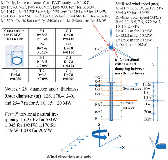
Figure 3.
Finite element model and the section dimensions of the final design result.
We used the torsional boundary conditions of the pile in three cases. The first case involved the use of the proposed t-z spring with the shear and torsional effects (Case 1: Shear + Tor), and the second case only used the t-z spring with only the shear effect, but the torsional degree of freedom at the pile bottom was fixed (Case 2: Shear). For the above two cases, the damping C and stiffness K between the tower and nacelle of the yaw system (Figure 3) were 2 × 10⁴ kN-m-s/rad and 9 × 10⁶ kN-m−1/rad, respectively, from the original setting of the DTU 10 MW turbine system [17]. The third case (Case 3: Note = Share + Tor + small Yaw K) was the same as the first case, but a larger C and smaller K were set as 1 × 10⁵ kN-m-s/rad and 3 × 10⁵ kN-m/rad, respectively, to reduce the torsional vibration from rotor blades.
As shown in Figure 3, the pile length was set to 50 m. Turbsim [24] and FAST [25] programs were first used to determine the wind loads and time-history blade forces and moments at the tower top. The structural analysis and steel design of each load case, as shown in Table 2 of ref. [19], were then performed to find the appropriate thickness of each member, where the loads included the dead, wave, and wind loads, as well as the hub wind loads from FAST. The irregular wave loads were determined from the second-order function theory [26]. The structural analysis and optimal steel design for the support structure were continuously iterated for nine cycles, where the DNV-RP-202 [27] was used in the steel design, including the shell stability and column buckling requirements of cylindrical shells. The total steel design weights of the two cases with different pile torsional boundary conditions were 3327 t and 3367 t for Cases 1 and 2, respectively; moreover, the design section dimensions were very similar to each other, where the result of Case 1 is shown in Figure 3.
Then, we changed the pile length between 32 to 45 m for the 10 MW case, and the support structure was subjected to a single load of (1) DLC 1.1 as the power production, (2) DLC 1.8 as the earthquake load (EQ) with the soil liquefaction effect, or (3) DLC I.2 as the tropical cyclone (TC), where the detailed load data are shown in Table 2. For load Case (1), Figure 4 shows the pitch angles of the three blades and the turbulence wind speed in the X-direction at the hub, and Figure 5 shows the dynamic force in the X-direction and the torsion in the Z-direction at the nacelle mass center using the FAST analysis results. The transient wind speed of the normal turbulence wind mode is from 2 to 18 m/s, and the pitch angle is often at the minimum angle to obtain the maximum wind power. Those results are quite normal under the power production of an OWT, and only the Z-direction torsion is a little large. It is noted that the Z-direction torsion from rotor blades is small if there is only a normal wind profile without turbulence. The large time–history torsion is induced from the normal turbulence wind model, as shown in Figure 5b, and this condition can almost not be avoided. After the rotor reaches the rated speed, the torsion caused by the rotor has a regular frequency at 1p, 3p, 6p, 9p, etc., which approaches the torsional natural frequency of the OWT support structure and causes resonance. Therefore, the time-dependent torsions of the support structure transferred from the rotor are very obvious even in power production conditions. Since the large torsion may greatly increase the pile shear force that should originally come from its own dead weight, this situation is disadvantageous for the vertical settlement of a monopile OWT. For load Case (2), where earthquake motion is combined with the power production at NTM-rated wind speeds, the situation is worse due to the combination of large rotor-induced torsion and seismic loading. However, for load Case (3), although the tropical cyclone wind speed is high, the monopile torsion induced from the parked rotor is often much smaller than that from the rotating rotor during the power production because the parked rotor does not generate resonance.
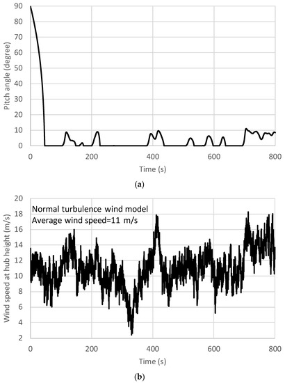
Figure 4.
The pitch angle of the three blades and the X-direction turbulence wind speed at the hub under DLC 1.1 with the average speed of 11 m/s using the FAST simulation. (a) Pitch angle of the three blades; (b) X-direction turbulence wind speed.
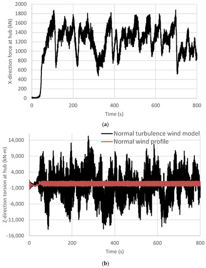
Figure 5.
The X-direction forces and Z-direction torsion at the mass center of the nacelle under the normal turbulence wind model (DLC 1.1) and the normal wind profile (DLC 2.5) with the average wind speed of 11 m/s using the FAST simulation. (a) X-direction forces (Normal turbulence wind model); (b) Z-direction torsion.
Figure 6 shows that the vertical settlement of the pile at the seabed varies with the used pile length for various load cases. This figure indicates the following features:
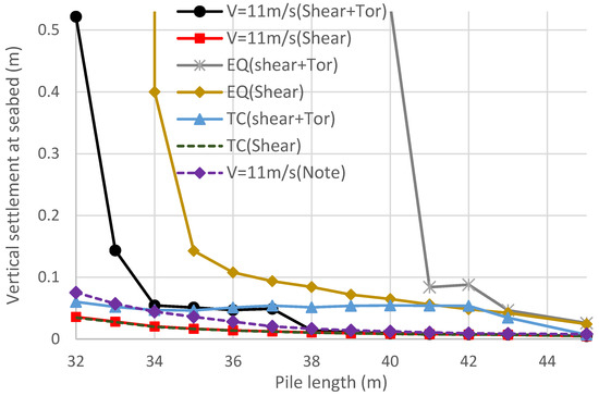
Figure 6.
The changes in the pile vertical displacement in the sea bed with the used pile length for the 10 MW case under the loads of DLC 1.1 (Vhub = 11 m/s), DLC 1.8 (0.32 g earthquake and Vhub = 11.4 m/s), and DLC I.2 (Tropical cyclone Vhub = 72 m/s) (Note = (Shear + Tor) the yaw stiffness equal to 3 × 10⁵ kN-m/rad).
(1) For the power production situation (Vhub = 11 m/s), when the pile length is less than 37 m, the pile vertical settlement of Case 1 increases with the decrease in the pile length, but it is almost independent of the pile length for Cases 2 and 3. When the pile length is less than 34 m, the pile vertical settlement of Case 1 increases significantly. However, the situation in Cases 2 and 3 has not changed much. The reason for this can be seen in Figure 7, which shows the element shear forces changing with the element displacements for the pile length of 37 m, where the result is obtained from the t-z spring element at the bottom of the pile. This figure shows that the nonlinear effect of Cases 2 and 3 is not obvious since the major loading for the t-z springs comes from the dead weight, and the torsion of the support structure is independent of this type of spring. However, for Case 1, using the proposed t-z spring with shear and torsional effects, the nonlinear behavior is obvious because the dynamic torsions from the support structure increase the cyclic shear stresses of the t-z springs along the pile. Thus, the large yield shear stresses of the t-z springs lead to a loss in the support force of the pile and cause the great settlement and rotation of the support structure.
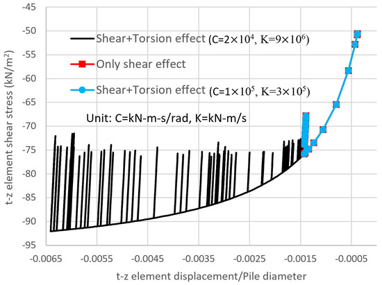
Figure 7.
The changes in the curves of shear forces with displacements at the end of 40 m pile for the three cases under a load of DLC 1.1 with an average speed of 11 m/s.
(2) For Case 3, the small yaw stiffness can isolate the rotor-induced cyclic torsion transferring to the support structure [28], so its settlement behavior is similar to that of Case 2. It is noted that this situation was discovered under normal loading conditions during the power production (DLC 1.1) with an acceptable pile length of 37 m, while the traditional t-z spring (Case 2) cannot solve this condition appropriately. However, using the proposed t-z spring with the shear and torsional effect (Case 1) can overcome this shortcoming, and moreover, it will not change the finite element program and model to any great degree.
(3) Another important discovery of the above analyses is the different results of Cases 1 and 3. This is because near resonance occurs for Case 1, where the first torsional natural frequency of Case 1 (1.045 Hz) is close to two times the 3P frequency, as follows:
where is the two times the 3P frequency, and is the 3P frequency due to the rated rotor speed (9.6 rpm) for the DTU 10 MW OWT. The first torsional natural frequency (FT1) of Case 3 is 0.275 Hz, which is far away from and . Moreover, the rotor-induced torsions with frequencies larger than FT1 can be reduced [29]. We also set a relatively large damping of the yaw system, so the time–history torsion transferred from rotor blades can be further reduced. This situation can be well simulated using the proposed t-z spring model. It is noted that the large torsion may not cause the failure of the tubular section of the monopile OWT because the tubular section, different from the opened section, can support significantly large torsion. However, the combination of the shear force from the vertical load and z-direction torsion may be greater than the soil shear resistance, which is much smaller than the soil bearing resistance, so large vertical and rotation displacements will cause the monopile OWT to fail.
(1) For the earthquake (EQ) during power production, as shown in Figure 6, the vertical settlement considering the shear and torsion effect is the most critical in all the analysis results. This is because the vertical seismic load, soil liquefication, and rotor-induced torsions all increase the settlement in the vertical direction. The figure also shows that considering only soil–pile shear force is not conservative enough for the vertical settlement calculation, using conventional t-z springs still requires approximately 15% of the pile length to avoid large vertical settlements.
(2) For the tropical cyclone case, the rotor blades are parked under an extreme turbulent wind model (EWM) with the Vhub of 72 m/s from 30° of the X direction, where the yaw misalignment is 60° from the X direction. The reason to use this setting is that it requires large member sections in the steel design for various tropical cyclone conditions, as shown in Table 2 of ref. [19]. The parked rotor-induced torsions are still large due to the 30° wind direction and the yaw misalignment. However, the main frequency of the torsion is much smaller than the structural natural frequency in the vertical rotation direction, so the condition of resonance and near resonance does not occur. The time–history torsion of the support structure is not large, and the vertical settlement is controlled by the vertical shear force. Thus, the results of Cases 1 and 2 boundary conditions are not very different.
3.2. For NREL 5 MW, IEA 15 MW, and 20 MW Wind Turbine Systems
In this section, OWT support structures for NREL 5 MW [30], IEA 15 MW [31], and 20 MW [32] wind turbines in 25 m deep water are investigated to achieve analytical differences of the vertical settlement under t-z springs with and without the proposed torsional effect. The analysis procedure is the same as in Section 3.1, where only boundary condition Cases 1 and 2 mentioned in Section 3.1 are performed. The section properties of the three analyzed OWT support structures are shown in Table 3, and Figure 8 shows that the vertical displacement of the pile at the seabed varies with the used pile length for the three cases, where the seismic and tropical cyclone loads are the same as those of Section 3.1, and the NTM wind load is IEC 61400-3 DLC 1.1 with an averaged wind speed of 25 m/s. This figure indicates the similar conclusion as that of the 10 MW cases, as follows:
Table 3.
The section properties of the 5, 10, 15, and 20 MW OWT support structures used in Section 3.2 (C = column, P = pile, and T = tower as shown in Figure 3).
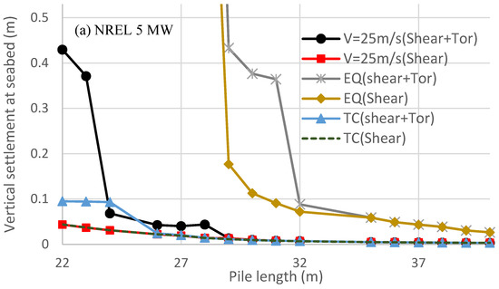
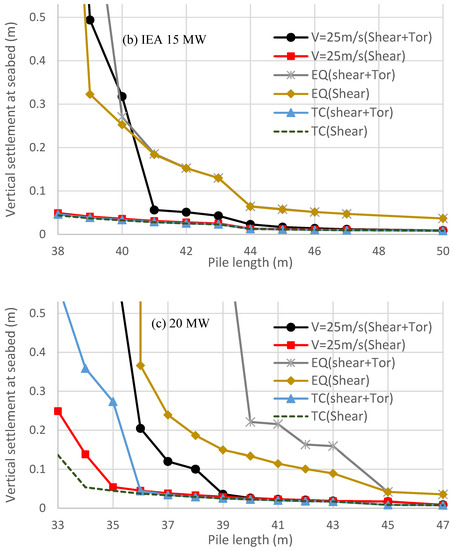
Figure 8.
The changes in the pile vertical displacement in the sea bed with the used pile length for the 5, 15, and 20 MW cases under loads of DLC 1.1 (Vhub = 25 m/s), DLC 1.8 (0.32 g earthquake and Vhub = 11.4 m/s), and DLC I.2 (Tropical cyclone Vhub = 72 m/s). (a) NREL 5 MW; (b) IEA 15 MW; (c) 20 MW.
(1) The earthquake during the power production causes critical vertical settlement, while using t-z springs with the torsional effect to calculate the pile settlement can obtain a conservative and safe result.
(2) During power production, the rotor-induced time–history torsion can be magnified by the support structure, which is critical for the first torsional natural frequency close to f6p (10 MW case) or f9p (other cases). The ratios of the maximum torsion at the seabed over the maximum torsion at the rotor are 2.2, 4.8, 2.5, and 2.9 for 5, 10, 15, and 20 MW cases, respectively. Thus, Figure 6 and Figure 8 indicate that the combination of the shear and torsional effect will cause a large settlement of the OWT support structure when the pile length is not in a conservative design.
(3) Under loads of tropical cyclones, the parked rotor often does not cause large time–history torsion on the support structure, so the settlement of the structure is smaller than that of the seismic load or even the power production load.
The above conditions are similar to those of the 10 MW case, which means that if the time–history torsion of the monopile is not taken into account, different scales of OWT support structures may cause the above problems. Furthermore, this happens in the case of power production, which is a common situation for OWT support structures. The problem is even worse if foundation scour occurs since scour can induce excessive displacement and bending moments in an OWT structure under combined loads, threatening its safe operation [33]. However, this problem can be overcome using the simple proposed method for conventional t-z springs.
Suction piles, similar to monopiles, have large cross-sectional diameters, and we can demonstrate that fatigue calculations for jacket structures with suction piles may not be correct if conventional t-z springs without torsional effect are used. The illustration of the complex finite element model is omitted here, and only the finite element results of the support structure using 15 MW OWT jacket three-leg suction piles are discussed. As shown in Figure 9, three-dimensional beam elements were used to model the pile, and the p-y, t-z, and Q-z nonlinear springs were used to model the soil–structure interaction. The finite element analysis and fatigue design indicate that the column thickness at joint A (Figure 9) requires 10.7 cm using the proposed t-z spring with the torsional effect, while it requires 17.7 cm using the conventional t-z spring. The reason is that the oscillation of the suction pile in the vertical direction cannot be avoided because there is no torsional constraint.
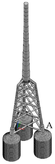
Figure 9.
A 15 MW OWT jacket support structure with three-leg suction piles in 70 m deep water (suction pile diameter = 22 m, length = 30 m; p-y, t-z, and Q-z nonlinear springs for soil–structure interaction analysis).
The vertical soil resistance of the wind turbine support structure is often modelled using t-z springs, but traditional t-z springs cannot be used to simulate the torsion of the pile appropriately. Thus, this paper developed a t-z spring with both shear and torsional effects so that the proposed t-z spring not only can support the shear forces but also the torsions from the pile. The major advantage of the proposed method is that the formulations are simple, where only one factor dependent on known data is used to modify the traditional stiffness of the t-z spring. Then, this spring can be used to simulate piles with shear forces and torsions appropriately, and the traditional fixed boundary condition of the torsional degrees of freedom is not necessary.
It is unavoidable for dynamic torsions to be generated from the unbalanced forces of rotating blades under turbulent wind loads. For the monopile foundation, the torsion will only generate shear stress between the pile surface and the soil, which is different from the jacked-type foundation in that the torsion can be transformed into the lateral force supported by the p-y spring. Generally, torsion will not cause the section failure of the monopile foundation because the tubular section, a closed section, has a large capacity for torsion. However, the shear resistance of the soil is much smaller than the bearing capacity of the soil, and it is a weak point of the monopile foundation. The combined shear stress from the vertical load and the z-direction torsion may cause large vertical and rotation displacements, which will lead to the failure of the monopile OWT. In this paper, 5, 10, 15, and 20 MW OWT support structures were analyzed under power production, seismic, and tropical cyclone loads. The finite element results indicate that the above condition can be found in the power production under a non-conservative pile length and is even critical during the power production under earthquakes. This situation will be worse when the natural frequency of the first z-direction rotation is close to the integer multiples of the 3P frequency. This near resonance of the vertical rotation mode cannot be found using the traditional t-z spring, while the proposed t-z spring with the shear and torsional effect can simulate this situation well without requiring excessive changes to the finite element program and model.
Author Contributions
S.-H.J.: Conceptualization, Methodology, Software, Data curation, Writing—original draft. C.-S.C.: Visualization, Investigation, Software, Validation. H.-H.H.: Validation, Writing—Reviewing. All authors have read and agreed to the published version of the manuscript.
Funding
A part of this study was supported by the National Science Council, Taiwan, under contract number: 109-2221-E-006-012-MY3.
Data Availability Statement
Data will be made available on request.
Conflicts of Interest
The authors declare that they have no known competing financial interests or personal relationships that could have appeared to influence the work reported in this paper.
Abbreviations
| API | American Petroleum Institute |
| 3D | Three dimensional |
| D | The diameter of a tubular section (m) |
| d | The total displacement of the t-z element (m) |
| DTU | Technical University of Denmark |
| DLC | Design load cases |
| EWM | Turbulent extreme wind speed model |
| F1P | The rotor frequency at the rated power (Hz) |
| F3P | Three times of F1P (Hz) |
| F6P | Six times of F1P (Hz) |
| F9P | Nine times of F1P (Hz) |
| FT1 | The first torsional natural frequency (Hz) |
| IEA | International Energy Agency |
| IEC | International Electrotechnical Commission |
| A section length of the element (m) | |
| NTM | Normal turbulence model |
| NSS | Normal sea state |
| NREL | National Renewable Energy Laboratory |
| NPD | A nonlinear proportional derivative |
| OWT | Offshore Wind Turbine |
| PGA | Peak ground acceleration |
| pult | the ultimate earth resistance for p-y curve (kN/) |
| qult | the ultimate tip resistance for the Q-z curve (kN/) |
| R | The radius of a tubular section (m) |
| T | Torsion in the axial direction of the pile (kN-m) |
| tult | the ultimate side friction for the t-z curve (kN/) |
| Vhub | 10-min. Average wind speed at the hub height (m/s) |
| Vr | Rated wind speed (m/s) |
| z | The displacement of the t-z curve spring (m) |
| θ | The twist angle of the t-z curve spring (rad) |
| The total shear stress along the pile surface of the t-z element | |
| The ultimate resistance of the t-z element (kN/m2) | |
| γ | The submerged weight density (kN/m3) |
| ψ | The submerged internal frictional angle (degree) |
References
- Yu, H.; Zeng, X.; Li, B.; Lian, J. Centrifuge modeling of offshore wind foundations under earthquake loading. Soil Dyn. Earthq. Eng. 2015, 77, 402–415. [Google Scholar] [CrossRef]
- Anastasopoulos, I.; Theofilou, M. Hybrid foundation for offshore wind turbines: Environmental and seismic loading. Soil Dyn. Earthq. Eng. 2016, 80, 192–209. [Google Scholar] [CrossRef]
- Kaynia, A.M. Seismic considerations in the design of offshore wind turbines. Soil Dyn. Earthq. Eng. 2019, 124, 399–407. [Google Scholar] [CrossRef]
- Wang, X.; Zeng, X.; Yang, X.; Li, J. Seismic response of offshore wind turbine with hybrid monopile foundation based on centrifuge modelling. Appl. Energy 2019, 235, 1335–1350. [Google Scholar] [CrossRef]
- Wang, X.; Zeng, X.; Li, X.; Li, J. Liquefaction characteristics of offshore wind turbine with hybrid monopile foundation via centrifuge modelling. Renew. Energy 2020, 145, 2358–2372. [Google Scholar] [CrossRef]
- Staubach, P.; Wichtmann, T. Long-term deformations of monopile foundations for offshore wind turbines studied with a high-cycle accumulation model. Comput. Geotech. 2020, 124, 103553. [Google Scholar] [CrossRef]
- Shi, S.; Zhai, E.; Xu, C.; Iqbal, K.; Sun, Y.; Wang, S. Influence of Pile-Soil Interaction on Dynamic Properties and Response of Offshore Wind Turbine with Monopile Foundation in Sand Site. Appl. Ocean Res. 2022, 126, 103279. [Google Scholar] [CrossRef]
- Basack, S.; Sen, S. Numerical Solution of Single Pile Subjected to Simultaneous Torsional and Axial Loads. Int. J. Geomech. 2014, 14, 06014006. [Google Scholar] [CrossRef]
- Hamed, Y.; Aly, A.A.; Saleh, B.; Alogla, A.F.; Aljuaid, A.M.; Alharthi, M.M. Nonlinear Structural Control Analysis of an Offshore Wind Turbine Tower System. Processes 2019, 8, 22. [Google Scholar] [CrossRef]
- Nimbalkar, S.S.; Punetha, P.; Basack, S.; Mirzababaei, M. Piles Subjected to Torsional Cyclic Load: Numerical Analysis. Front. Built Environ. 2019, 5, 24. [Google Scholar] [CrossRef]
- Jiang, J.; Wang, S.W.; Ou, X.D.; Fu, C.Z. Analysis of the bearing characteristics of single pile under the T -> V loading path in clay ground. Rock Soil Mech. 2020, 41, 3573–3582. [Google Scholar] [CrossRef]
- Mehra, S.; Trivedi, A. Pile Groups Subjected to Axial and Torsional Loads in Flow-Controlled Geomaterial. Int. J. Geomech. 2021, 21, 04021002. [Google Scholar] [CrossRef]
- Altan, B.D.; Gungor, A. Examination of the Effect of Triangular Plate on the Performances of Reverse Rotating Dual Savonius Wind Turbines. Processes 2022, 10, 2278. [Google Scholar] [CrossRef]
- Al-Quraan, A.; Al-Mahmodi, M.; Alzaareer, K.; El-Bayeh, C.; Eicker, U. Minimizing the Utilized Area of PV Systems by Generating the Optimal Inter-Row Spacing Factor. Sustainability 2022, 14, 6077. [Google Scholar] [CrossRef]
- Radaideh, A.; Bodoor, M.M.; Al-Quraan, A.; Vallée, F. Active and Reactive Power Control for Wind Turbines Based DFIG Using LQR Controller with Optimal Gain-Scheduling. J. Electr. Comput. Eng. 2021, 2021, 1218236. [Google Scholar] [CrossRef]
- Boulanger, R.W.; Curras, C.J.; Kutter, B.L.; Wilson, D.W.; Abghari, A. Seismic soil-pile-structure interaction experiments and analyses. J. Geotech. Geoenvironmental Eng. 1999, 125, 750–759. [Google Scholar] [CrossRef]
- Bak, C.; Zahle, F.; Bitsche, R.; Kim, T.; Anders, Y.; Henriksen, L.C.; Natarajan, A.; Hansen, M.H. Description of the DTU 10 MW Reference Wind Turbine; DTU Wind Energy: Lyngby, Denmark, 2013; Available online: https://orbit.dtu.dk (accessed on 30 December 2022).
- Fu, D.F.; Zhang, Y.H.; Aamodt, K.K.; Yan, Y. A multi-spring model for monopile analysis in soft clays. Mar. Struct. 2020, 72, 20. [Google Scholar] [CrossRef]
- Ju, S.H.; Huang, Y.C.; Hsu, H.H. Parallel Analysis of Offshore Wind Turbine Structures under Ultimate Loads. Appl. Sci. 2019, 9, 14. [Google Scholar] [CrossRef]
- Ju, S.H.; Huang, Y.C. Analyses of offshore wind turbine structures with soil-structure interaction under earthquakes. Ocean Eng. 2019, 187, 11. [Google Scholar] [CrossRef]
- Zhang, Q.Y.; Zhang, Y.; Lin, H.D.; Feng, L. Numerical investigation on bearing capacity of OWT foundation with large diameter monopile under Seismic load. Appl. Ocean. Res. 2021, 108, 102518. [Google Scholar] [CrossRef]
- American Petroleum Institute. Recommended Practice for Planning, Designing and Constructing Fixed Offshore Platforms—Load and Resistance Factor Design; API RP 2A-LRFD; American Petroleum Institute: Washington, DC, USA, 1997; Available online: https://www.api.org (accessed on 30 December 2022).
- Simon, J. Parameter identification for dynamic analysis of pile foundation using nonlinear p-y method. In Proceedings of the Second Conference of Junior Researchers of Civil Engineering, Budapest, Hungary, 17–18 June 2013. [Google Scholar]
- Jonkman, B.J.; Buhl, M. Turbsim User’s Guide v2.00.00; Technical Report No. NRELEL-500-36970; National Renewable Energy Laboratory (NREL): Golden, CO, USA, 2004. [Google Scholar]
- Jonkman, J.M.; Buhl, M. FAST User’s Guide; Technical Report NREL/EL-500-38230; National Renewable Energy Laboratory (NREL): Golden, CO, USA, 2005. [Google Scholar]
- Sharma, J.N.; Dean, R.G. Second-order directional seas and associated wave forces. Soc. Pet. Eng. J. 1981, 21, 129–140. [Google Scholar] [CrossRef]
- As, D.N.V. Buckling Strength of Shells, DNV-RP-C202. 2013. Available online: https://www.dnv.com (accessed on 30 December 2022).
- Ju, S.H. Increasing the fatigue life of offshore wind turbine jacket structures using yaw stiffness and damping. Renew. Sustain. Energy Rev. 2022, 162, 112458. [Google Scholar] [CrossRef]
- Chopra, A.K. Dynamics of Structures: Theory and Applications to Earthquake Engineering; Prentice Hall: Hoboken, NJ, USA, 1995. [Google Scholar]
- Jonkman, J.M.; Butterfield, S.; Musial, W.; Scott, G. Definition of a 5-MW Reference Wind Turbine for Offshore System Development; Technical Report NREL/TP-500-38060; National Renewable Energy Laboratory (NREL): Golden, CO, USA, 2009. [Google Scholar]
- Gaertner, E.; Rinker, J.; Sethuraman, L.; Zahle, F.; Anderson, B.; Barter, G.; Abbas, N.; Meng, F.; Bortolotti, P.; Skrzypinski, W.; et al. Definition of the IEA 15-Megawatt Offshore Reference Wind; NREL/TP-5000-75698; National Renewable Energy Laboratory: Golden, CO, USA, 2020. [Google Scholar]
- Ju, S.H.; Huang, Y.C.; Huang, Y.Y. Study of optimal large-scale offshore wind turbines. Renew. Energy 2020, 154, 161–174. [Google Scholar] [CrossRef]
- Liang, F.; Yuan, Z.; Liang, X.; Zhang, H. Seismic response of monopile-supported offshore wind turbines under combined wind, wave and hydrodynamic loads at scoured sites. Comput. Geotech. 2022, 144, 104640. [Google Scholar] [CrossRef]


Disclaimer/Publisher’s Note: The statements, opinions and data contained in all publications are solely those of the individual author(s) and contributor(s) and not of MDPI and/or the editor(s). MDPI and/or the editor(s) disclaim responsibility for any injury to people or property resulting from any ideas, methods, instructions or products referred to in the content. |
© 2023 by the authors. Licensee MDPI, Basel, Switzerland. This article is an open access article distributed under the terms and conditions of the Creative Commons Attribution (CC BY) license (https://creativecommons.org/licenses/by/4.0/).