Abstract
This study presents a pointer-driven controller for an instrument panel. The proposed pointer utilizes the permanent magnet (PM) stepping motor produced by the Japanese company NMB. This stepping motor is vibration-proof and tolerates noise jamming as well as wind and rain exposure. Moreover, it has no mechanical structures and is low cost. Most importantly, it features accurate positioning; therefore, it can be used to measure vehicle speed, engine speed, fuel capacity, and temperature. However, the PM stepping motor of the NMB pointer requires 10 degrees for each step, and this low resolution results in roll hesitation as its steps. The aim of the current paper was to solve the problems of the large angle size and low resolution associated with this stepping motor. Based on two-phase excitation, we propose driving the motor using pulse width modulation (PWM). Specifically, we divided each 10-degree step into 100 equal parts. In other words, every step is 0.1 degrees. The resolution of pointer rotation can be increased by 100-fold by using the approach proposed in this paper. When applied to vehicle (or locomotive) instruments, the pointer can move very smoothly on the tachometer or oil gauge.
1. Introduction
Stepping motors are widely used in digital devices and computer peripheral equipment such as printers, plotters, and manipulators. Essentially, they divide the full rotation of a motor into an equal number of steps. The driving technologies of stepping motors include full stepping, half-stepping, and micro-stepping [1]. For applications requiring precise positioning, even the resolution of most micro-stepping motors is not sufficient. Therefore, in Europe and the United States, pulse width modulation (PWM) has been applied to divide the exciting current of each coil into smaller parts to increase the resolution from 0.36° (360°/1000) to 0.0072° (360°/50,000). Micro-stepping is a technique that divides the motor’s basic step angle into smaller steps to achieve low-resonance, low-noise operation at very low speeds by controlling the current fed to the motor coils. Micro-steps improve the resolution of a motor and make the rotation smoother. They also improve the speed, torque, and action response time of a motor while inertia and vibration during rotation are reduced. This makes micro-stepping a suitable driving technology for applications requiring high speed and precision [2]. For example, in the semiconductor manufacturing industry, motors and driving circuits must feature highly accurate positioning. For these applications, 25,000 steps per revolution are implemented on an X-Y mobile platform. With 10 pitch screws per inch, 250,000 parts can be divided on the silicon surface per inch.
The main problem of stepping motor in precision positioning application is that each step angle of stepping motor is quite large, approximately 1/200 of a revolution or 1.8 degrees. The motor shaft with such a large stepping angle may oscillate at the low speed resonance point. Ways to overcome the shortcomings of low resolution and vibration and effectively reduce vibration and noise in the low-speed field has become the most important research topic for driving stepping motors. Stepping motors are usually classified according to the number of phases in their structure, and two-phase and five-phase versions are common designs. Although the two-phase version is widely used, the performance advantages of the five-phase stepping motor make it the preferred choice in some applications. The following papers deal with micro-step operation of five-phase permanent magnet stepper motors driven in constant current mode [3,4,5]. The papers also compare the control and positioning characteristics of motors with different numbers of phases, two, three and five. The larger the phase number, the smaller the positioning deviation of the motor. Barabas et al. proposed the micro-stepping scheme using five-phase stepping motor in both clockwise and counter-clockwise modes implemented under various speeds [6]. Adhikari et al. presented a method and implementation of sinusoidal PWM waveform generation for a five-phase five-level converter using FPGA technology [7]. Multilevel converters require an increased number of switches operating in parallel, and FPGAs are best choice to handle massive parallelism algorithms.
In the full-step driving mode, the A and B two-phase motor coils are all turned on, and the currents are equal in magnitude. In order to make the stepping motor have micro-stepping effect, we gradually reduce the current of a certain phase and gradually increase the current of the other phase, that is, change the magnitude and direction of the current in each coil, so that the motor rotor can stay at any position. Equally dividing the current magnitude into various different magnitude values, the full step can be subdivided into smaller micro-steps. Bednarski et al. proposed a family of generalized micro-stepping signal shapes, ranging from sine–cosine micro-stepping to quadrature micro-stepping. A series of experiments is performed on a test bench to analyze the influence of different signal shapes on the performance of the motor in both load and no-load conditions [8]. Most of the micro-step driving signals are completed by properly deploying the current between the A and B phases according to the relationship between the sine and the cosine. Baluta developed a high-performance system for stepping motor control in the micro-stepping mode, which was designed and implemented with a L292 ASIC manufactured by SGS-THOMSON, Microelectronics Company [9]. Patel et al. proposed the design and implementation of bipolar micro-stepping control for disc rotor type PM stepping motor. The experimental results show that the micro-stepping control system improves the positioning accuracy and eliminates the low-speed ripple and resonance effects [10]. Jagtap et al. adopted power supply, micro-stepping driver, NEMA 17 stepping motor and other hardware devices to implement the micro-stepping motor control system on the working platform of NI LabVIEW software, where NI myRIO is used as the interface between the software program and the stepping motor hardware [11]. However, some of the most important factors that limit micro-stepping performance, as well as methods of overcoming these limitations, are discussed in [12]. The research topic of this paper focuses on the PWM cutting method of the step angle of the micro-stepping motor. As for the control algorithm of the micro-stepping motor, it is pointed out in the literature that the fuzzy controller seems to play an important role and is also a feasible method. The design of controller must consider the influence of motor power supply noise, load variation interference and delay on the system. For relevant discussion, please refer to [13,14,15,16].
The aim of this research paper was to apply PWM to two-phase excitation to cut the step distance of a PM stepping motor. We achieved 3600 steps per revolution from 36 steps per revolution and reduced the step angle from to , successfully improving motor resolution while maintaining the torque of two-phase excitation. As a result of the finer stepping angle, not only is the vibration of the motor smaller and smoother, but inertia is also smaller. Our results can be applied to pointer-type instruments for locomotives, electric tricycles, and automobiles. When the engine is started, the associated noise affects the operation of the embedded microcontroller. Without the protection of a watchdog, it is likely to crash. In an environment of high noise interference, the PIC chip is an appropriate choice, as it is resistant to noise interference [17]. The remainder of this paper is organized as follows. Section 2 of this paper describes the structure and driving method of stepping motor, including one-phase excitation, two-phase excitation and one-two-phase excitation. The PWM micro-stepper motor drive principle and general formula proposed in this paper are introduced in Section 3, which is applicable to variable types of stepping motor. In Section 4, we present an algorithm to realize the PWM micro-stepping cutting method on practical vehicle instrument panel. Section 5 shows the experimental results and function testing. Section 6 presents our conclusions and future works.
2. Stepping Motor Structure and Driving Method
A stepping motor is composed of rotors and stators. In a five-phase stepping motor, for example, the motor bearing runs through a cylindrical magnet, onto which two rotors are clamped. Rotor 1 is magnetized to the N pole, and Rotor 2 is magnetized to the S pole, shown in Figure 1. The outer rings of the rotors are engraved with small gear-like teeth. The rotors shown in Figure 2 each have 50 teeth. The interval between each tooth on the N pole is , and the interval between each tooth on the S pole (rotor 1) and N pole (rotor 2) is .
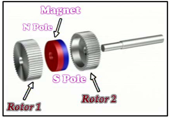
Figure 1.
Structure of rotor component.
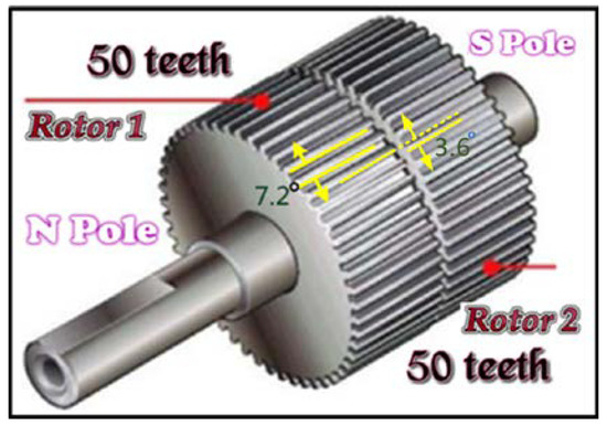
Figure 2.
Small gear-like teeth.
This structure is surrounded by the stator, on which there are ten protrusions with teeth functioning as magnetic poles, as shown in Figure 3. Each pole is covered with a coil. The poles facing each other are also connected by a coil. The coils are divided into five groups: A, B, C, D, and E phases. This creates the five-phase stepping motor depicted in Figure 4.
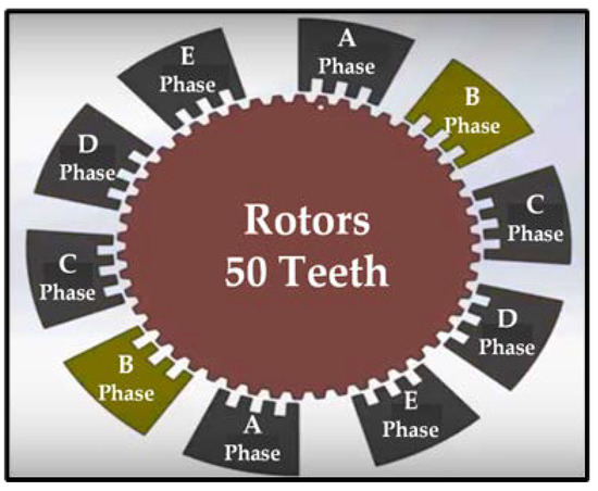
Figure 3.
Structure of stator.
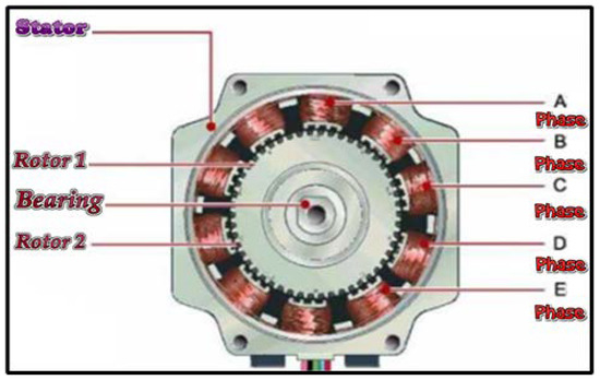
Figure 4.
Five-phase stepping motor.
The five phases represent that there are five groups of coils (n = 5) and 10 magnetic poles inside the stepping motor; each rotor has 50 small teeth (= 50), so the spacing of small teeth on the same rotor is , and the spacing of small teeth on rotor 1 and rotor 2 is . When the coils of the stepping motor are excited, the step angle of each step is
Similarly, the two phases represent that there are two groups of coils (n = 2) and four magnetic poles inside the stepping motor. Each rotor has 50 small teeth ( = 50). The step angle of each step is
For the convenience of illustration, this paper takes the simplest motor structure as an example: the stepping motor is two-phase, four-pole (S1–S4), and the rotor outer ring does not process any small teeth (). According to Formula (2), the stepping angle of the stepping motor is 90 degrees, that is, only four steps are needed for each revolution. In general, the most common driving modes of stepping motors are one-phase excitation, two-phase excitation, and one-two phase excitation, which are discussed below.
2.1. One-Phase Excitation
In a one-phase motor, only one coil is excited, and the excitation changes once, which makes the motor move one step forward. This kind of motor has small torque, large vibration, and small power consumption. If the average consumption current is I and the applied voltage is V, the consumption power is P = VI. Figure 5 presents a schematic diagram of a one-phase excitation rotor movement. The S1–S4 coils are connected in sequence, the N pole of the rotor rotates clockwise with coil excitation, and the rotor rotates 90 degrees each time. The yellow part in the figure indicates excitation of a coil.
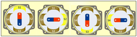
Figure 5.
One-phase excitation.
2.2. Two-Phase Excitation
Two-phase excitation is the most widely used driving method. In a two-phase motor, two coils are excited at the same time. Every time the excitation changes, the motor moves forward 90 degrees. However, the torque of two-phase excitation is large, and the vibration is small. The power consumption is P = 2VI, which is twice that of one-phase excitation. Figure 6 shows the motion of a two-phase excited rotor. When S1 and S2 are connected simultaneously, the N-pole rotor is in the center of S1 and S2. During the next excitation, S2 and S3 are energized with current, the N-pole rotor rotates to the center of S2 and S3, and the step angle is 90 degrees. Therefore, two-phase excitation offers low resolution.
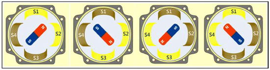
Figure 6.
Two-phase excitation.
2.3. One-Two-Phase Excitation
After one coil is magnetized, it will be magnetized by two coils, and then it will be magnetized by one coil, and so on. When the excitation is changed in such a cycle, the step angle of each excitation is 45 degrees, and the resolution is twice as high as that of the previous two driving methods. However, the power consumption is P = 1.5VI. Figure 7 shows the motion of a one-two-phase excited rotor. When S1 and S2 are connected simultaneously, the N-pole rotor is in the center of S1 and S2. However, in the next stage, only S2 is energized with current, and the N-pole rotor can only face S2. The step angle is then reduced to 45 degrees, which doubles the resolution.
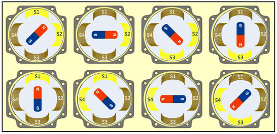
Figure 7.
One-two-phase excitation.
3. PWM Micro-Stepper Motor Drive Technology
The concept proposed in this paper using PWM to cut the step angle is new, which is quite different from the method proposed in other references. Take a two-phase four-wire (A(S1), B(S2), (S3), (S4)) stepping motor as an illustration; there are two ideas worth explaining.
(1) In the past literature, the cutting step angle is based on the one-phase excitation drive mode. For the excitation current of A-phase and B-phase coils, the excitation current of one phase increases slowly, and the excitation current of the other phase gradually decreases to meet the requirements of cutting micro-step angle. To rotate the stepper motor to the specified cutting angle, the current can be varied in one winding with a sine function of an angle and in the other winding with a cosine function of as shown in Figure 8. At any angle , the resultant current remains same and equal to which is the rated current in the windings.
where is the instantaneous current in stator winding A, is the instantaneous current in stator winding B. is the angle in electrical degrees from a full step position (micro-stepping angle) and is the rated current of winding.
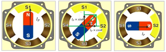
Figure 8.
One-phase excitation micro-step drive.
However, the method proposed in this paper is based on the concept of two-phase excitation, directly adjusting A(S1), (S3) or B(S2), (S4) excitation current of these two groups of coils. Since the phase difference between the two coils is 180 degrees, the excitation current of the two coils can be changed in equal proportion. For example, the excitation current of A(S1) coil gradually decreases in the following manner: →0.8→0.6→ 0.4→0.2→0, and the excitation current of (S3) coil increases gradually in this way: 0→, and B(S2) still remains exciting current to achieve the goal of cutting step angle of 5 equal parts. Generally speaking, in practice, a single chip (embedded microcontroller) is mostly used to realize the control of micro-stepping motors. The valuable advantage of the method proposed is to avoid the calculation of sin–cos, which can greatly reduce the computational load of a single chip.
(2) On the other hand, in the previous literature, H bridge circuit is mostly used to generate excitation current of sin and cos, as shown in Figure 9. It is composed of two sets of power MOSFETs connected in series on each group of coils of the stepping motor. The power supply voltage is applied to the motor winding through the switch signal of MOSFETs, so that the drive current is generated through the winding inductance. Once the current reaches the set value, the H-bridge circuit will switch the control state, making the output current attenuate, and then the excitation current of sin and cos is generated, as shown in Figure 10. Observe the driving current in the Figure; strictly speaking, it should still be an analog signal, but the signal is held at each stage of cutting step angle. However, the approach of this paper is based on the digital signal point of view, and the excitation currents of the coils are changed by adjusting the duty cycle of the pulse wave. As a simple example, an analog voltage of 0~5 V can be used to control the brightness of LED. In fact, adjusting the duty cycle of PWM can also achieve the same goal.
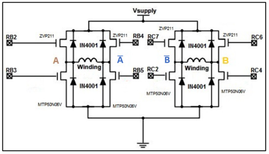
Figure 9.
H bridge circuit.
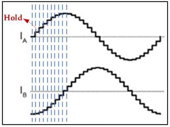
Figure 10.
Sin-Cos phase excitation.
Equation (1) suggests two approaches to improving the resolution of a stepping motor: increasing the number of stator coils or increasing the number of rotor gears. Both approaches risk greatly increasing both the complexity of processing and production cost. In this paper, we propose an innovative driving method which uses PWM to cut the steps of the motor into smaller parts. We consider as a case study the NMB pointer PM stepping motor with a two-phase stator and four poles (S1–S4). Each rotor of this motor has nine small teeth (), and the step angle is 10 degrees. We applied PWM to cut each step into five equal parts, resulting in a step angle of 2 degrees. We further applied PWM to cut each step into 100 equal parts, resulting in a step angle of 0.1 degrees, thereby meeting the requirements of precise positioning.
The selected stepping motor is driven by two-phase excitation. Four groups of GPIO lines inside the microcontroller PIC16F1507 are connected to four phases: A(S1), B(S2), (S3) and (S4). As described above, two-phase excitation lets the current pass through two coils at a time, and the power consumption of two-phase excitation is twice as much as that of one-phase excitation. Because the torque of two-phase is double that of one-phase, the motor rotates stably and can bear a heavier load than one-phase excitation. The control sequence of two-phase excitation is shown in Table 1. The control signals of each step are given in turn, and the PM stepping motor starts to rotate clockwise. The rotation angle of each step is 10°, which indicates that the motor is operating normally. PWM is then added to achieve the aims of this study.

Table 1.
Two-phase excitation and PWM drive sequence.
3.1. Micro-Step Angle of 2°
A traditional full-step driver uses bipolar current interaction to excite phase A or B to complete the step action. If one phase current is gradually reduced while the other phase current is gradually increased, the motor may stay in the middle of the step.
In Figure 11, we present the driving mode of the micro-step motor proposed in this paper. It is based on two-phase excitation. Each step is divided into five equal parts. Step 1-1: when S1 and S2 are connected with current simultaneously, the N-pole rotor is between S1 and S2. Step 1-2: when the current through S1 is reduced to 80% and that through S3 is increased to 20%, the N-pole rotor will rotate 2 degrees clockwise. Step 1-3: when the current through S1 is reduced to 60% and that through S3 coil is increased to 40%, the N-pole rotor will rotate another 2 degrees. In summary, the current of S1 coil decreases gradually, the current of S2 coil remains unchanged, while the current of S3 coil increases gradually, which drives the N-pole rotor to rotate more smoothly to achieve the purpose of micro-stepping motor cutting, shown in Table 1. The current strengths of 80%, 60%, 40%, and 20% represent the working cycle of PWM. Our experimental results showed that this approach succeeded in reducing the step angle from 10° to per step.
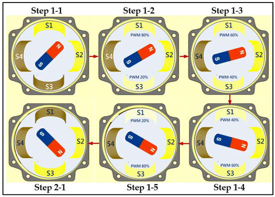
Figure 11.
Two-phase excitation PWM cutting sequence.
3.2. Micro-Step Angle of 0.1°
To fit within the specifications of locomotive instruments, the indicator of current speed must rotate from 0 km/hour to 180 km/hour. In other words, each step of the stepping motor rotates , which requires 2700 steps. Table 2 describes the driving mode of the proposed micro-step motor. We cut the step distance into 100 micro-steps, i.e., Step 1-1 to Step 1-100, Step 2-1 to Step 2-100, Step 3-1 to Step 3-100, and Step 4-1 to Step 4-100. If two-phase excitation is cut into 400 micro-steps, the stepping motor can turn in one cycle (Step 1–Step 4). To complete 2700 micro-steps, the cycle must be repeated six times, and the remaining 300 micro-steps can be achieved by performing Step 1, Step 2, and Step 3 once more.
Table 2.
Cutting method using PWM modulation signal.
3.3. Generalize PWM Cutting Approach
For a stepping motor with two phases (n = 2) and four magnetic poles, the stepper angle is shown in Equation (2). Each four-step cycle is a period which is designated as Step1, Step2, Step3, Step4, respectively. Assume that each step is further divided into N equal parts, and the micro-stepper angle becomes
After using PWM cutting approach, each step is divided into N equal parts, defined as Step x-y, where x = 1, 2, 3, 4, and y = 1, 2, …, N. The cutting stepper angle can be achieved by adjusting the PWM duty cycle in equal proportions. The increase and decrease in PWM duty cycle is
Considering each segmented stepper angle Step x-y, the increment and decrement of PWM duty cycle of excitation coil can be summarized as Table 3.
Table 3.
Micro-step angle Step x-y driving formula.
Where
Although the above discussion is completely for two-phase and four-pole stepping motors, in fact, the method we propose can be extended to any structure of stepping motors, such as tow-phase, three-phase and five-phase stepping motors. As long as the correct coil excitation mode is adopted, the proposed method can be applied. Take a five-phase stepping motor as an example; the motor is driven by five-phase excitation, as shown in Figure 12. According to the previous driving principle, the duty cycle of PWM can be sequentially increased or decreased in coils such as A and , B and , C and , D and , E and , respectively, to achieve the purpose of cutting micro-stepping angle.
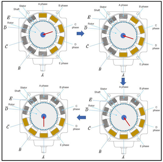
Figure 12.
Five-phase excitation for five-phase stepping motor.
4. Vehicle Instrument Drivers
When adding sensor elements to read engine speed, locomotive speed, fuel quantity, temperature, gasoline buoy, and oil and fuel quantity, we seek to change the sensor reading program while preserving the rest of the program structure. In this section, we present an algorithm to realize the driving technology of the PWM micro-stepping motor. The basic concept of the algorithm of the program and the related variables are as follows:
(1) The pointer of the speedometer is –, and the driving range of the micro-step motor is 0–2700 micro-steps. For each sampling time, the motor will step forward from N1 (0–2700) to N2 (0–2700).
(2) A set of registers (R5, R6) is defined to store the initial micro-step value N1. Another set of registers (R7, R8) stores the terminated micro-step value N2.
- ▪
- If (R7, R8) is greater than (R5, R6), [counter = (R7, R8) − (R5, R6)] the motor rotates in a clockwise direction.
- ▪
- If (R5, R6) is greater than (R7, R8), [counter = (R5, R6) − (R7, R8)] the motor rotates in an anti-clockwise direction.
(3) Counter represents the count of loops. We set
(4) P can be used to determine which interval the microstep to move is located in Step 1–Step 4. Table 4 shows the relationship between P value and the interval of Step 1–Step 4.
Table 4.
The relationship between P value and the interval of Step 1–Step 4.
(5) Q is used to set the duty cycle of the pulse width, where the high byte of PWM register = 100 − Q, and the low byte of PWM register = 0. We add 1 to the contents of registers (R5, R6).
(6) the following two cases are considered:
- ▪
- If , then the program jumps back to (6) and the stepping motor continues to drive in micro-steps.
- ▪
- If , then the motor has stepped from N1 to N2, and the next sampling is carried out.
5. Experimental Results and Functional Testing
In order to verify the feasibility of the system, a set of testing devices was established in the laboratory, as shown in Figure 13. The manufacturing process of the system was as follows:
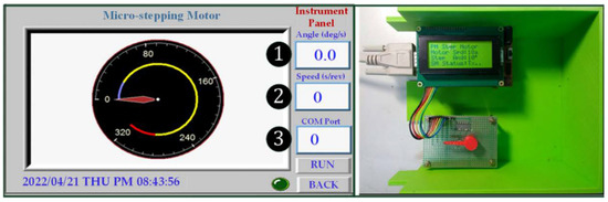
Figure 13.
Experimental device.
(1) We evaluated the PIC16F1507 produced by a well-established microchip company to determine whether its functions met our requirements, i.e., whether it was compatible with other component parts and whether it provided sufficient technical support.
(2) We evaluated the specifications and functions of the MT6071IE touch panel launched by Weintek to determine whether its functions met our requirements, i.e., whether the instrument diagram indicates data in the current register, RS232 serial communication interface, timer as the switch timing of the meter and whether it was suitable for real-world simulation.
(3) We used the PIC16F1507 microcontroller to design vehicle instruments as well as PWM technology to drive the NMB pointer PM stepping motor. Its functions included reading square wave signal produced by the Hall sensor by RA5(T1CLKI) and converting the analog voltage of external temperature, oil quantity, and battery life to digital voltage by RC0 (AN4). These functions were achieved using RA2 (PWM3), RC3 (PWM2), RC1 (PWM4), and RC5 (PWM1) of phases A, B, and of the stepping motor. In addition, the PIC16F1507 microcontroller uses a GPIO pin to drive a 16 × 4 text LCD module for digital information display. The prototype circuit was connected with the touch panel on the left through RS232 serial communication interface, the hardware architecture is shown in Figure 14.
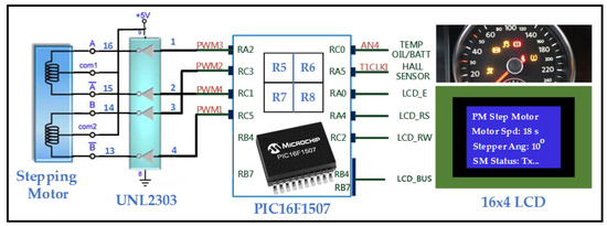
Figure 14.
Hardware architecture diagram.
(4) In addition, we also used three “Input” objects to set (1) the cutting angle of the motor and (2) the rotation speed of the motor, as well as (3) to display the working mode. After “Execute” is pressed, the parameters set on the touch panel are transmitted to the PIC16F1507 microcontroller through RS232 serial communication, which is then converted into PWM signal to drive the PM stepping motor. When the motor rotates, the pointer on the touch panel rotates synchronously to simulate a vehicle instrument.
PWM is a stepper motor drive method based on two-phase excitation, assuming that each step is divided into five equal parts, and the step angle is changed from the original 10 degrees to 2 degrees. Step 1 is divided into five steps, which are called Step 1-1 ~ Step 1-5 respectively. Further details of the simulation are as follows:
Step 1-1: the duty cycle of S1 (A) PWM signal is 100% and that of S3 () PWM signal is 0%; however, S2 (B) and S4 () PWM signal still remain 100% and 0%, respectively.
Step 1-2: the duty cycle of S1 (A) PWM signal is 80% and that of S3 () PWM signal is 20%; however, S2 (B) and S4 () PWM signal still remain 100% and 0%, respectively.
Step 1-3: the duty cycle of S1 (A) PWM signal is 60% and that of S3 () PWM signal is 40%; however, S2 (B) and S4 () PWM signal still remain 100% and 0%, respectively.
Step 1-4: the duty cycle of S1 (A) PWM signal is 40% and that of S3 () PWM signal is 60%; however, S2 (B) and S4 () PWM signal still remain 100% and 0%, respectively.
Step 1-5: the duty cycle of S1 (A) PWM signal is 20% and that of S3 () PWM signal is 80%; however, S2 (B) and S4 () PWM signal still remain 100% and 0%, respectively.
In Figure 15, we illustrate the PWM obtained by measuring S1 (A) and S2 (B) with an oscilloscope. means that each step occupies , and the width of the step is determined by the rotation speed of the motor. After this signal is triggered, the frequency scale is adjusted horizontally to the appropriate width. As shown in Figure 16, each Step 1-x requires approximately 2.8 ms and contains 10 PWM signals, and each PWM pulse period lasts . Step 1-4, for example, contains 10 PWM signals with a 40% duty cycle. Figure 17 and Figure 18 depict the simulation.
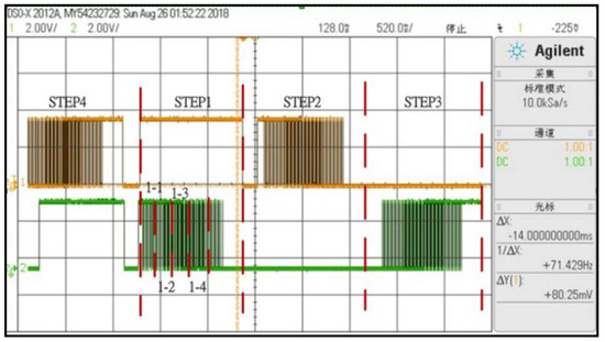
Figure 15.
Step angle cut into five parts for two-phase excitation.
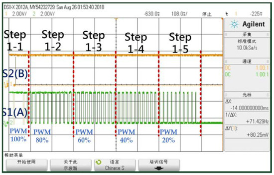
Figure 16.
Enlarged view of Step 1 divided into five equal parts.
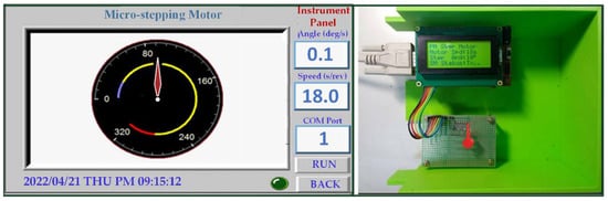
Figure 17.
Integrated test pointer located near 90 degrees.
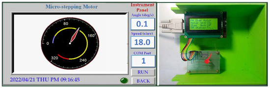
Figure 18.
Integrated test pointer moving toward 120 degrees.
6. Conclusions
In this paper, PWM is used to improve the resolution of a stepping motor. The resolution is increased from 36 steps per revolution to 3600 micro-steps per revolution. The step angle is reduced from 10° to 0.1° while maintaining the torque of two-phase excitation. When the motor is rotating, not only is vibration smaller and smoother, but inertia is also smaller, both of which greatly improve the action response time of the motor. This makes the motor suitable for high-speed high-precision applications such as motor and drive circuits in the semiconductor manufacturing industry. It also holds great potential for precision-grinding, rotating, and surface-polishing machines as well as other precise motion control such as optical scanning, inspection, disk machine manufacturing, and optical fiber manufacturing.
Author Contributions
P.-S.T. put forward the original idea of this paper and was responsible for the planning and implementation of the whole research plan; T.-F.W. is responsible for thesis writing and text editing; J.-Y.C. deduced the PWM driving technology in the micro-stepping system and implemented it with PIC16F1507 microcontroller; P.-T.T. established the hardware architecture and function verification of the micro-stepping system for instrument panel. All authors have read and agreed to the published version of the manuscript.
Funding
This research was funded by National Science and Technology Council (NSTC) (https://www.nstc.gov.tw, accessed on 5 January 2023), grant number NSTC 111-2221-E-007-126.
Institutional Review Board Statement
Not applicable.
Informed Consent Statement
Not applicable.
Data Availability Statement
Not applicable.
Acknowledgments
The authors would like to thank the National Science and Technology Council (NSTC) of Taiwan, China, for financially supporting this research under Contract No. NSTC 111-2221-E-007-126. (https://www.nstc.gov.tw, accessed on 5 January 2023).
Conflicts of Interest
The authors declare no conflict of interest.
References
- Acarnley, P. Stepping Motors a Guide to Theory and Practice, 4th ed.; The Institution of Engineers and Technology: London, UK, 2002. [Google Scholar] [CrossRef]
- McGuinness, J. Advantages of five phase motors in microstepping drive. In Proceedings of the IEE Colloquium on Stepper Motors and Their Control, London, UK, 25 January 1994. [Google Scholar] [CrossRef]
- Bellini, C.; Concari, G.F.; Toscani, A. Mixed-mode PWM for high-performance stepping motors. In Proceedings of the 30th Annual Conference of IEEE Industrial Electronics Society (IECON 2004), Busan, Republic of Korea, 2–6 November 2004. [Google Scholar] [CrossRef]
- Weerakoon, T.S.; Samaranayake, L. Development of a Novel Drive Topology for a Five Phase Stepper Motor. In Proceedings of the 2008 IEEE Industrial and Information Systems Conference, Kharagpur, India, 8–10 December 2008. [Google Scholar] [CrossRef]
- Farid, B.; Amar, O. A Study of New Techniques of Controlled PWM Inverters. Eur. J. Res. 2009, 32, 77–87. [Google Scholar]
- Barabas, Z.A.; Morar, A. High Performance Microstepping Driver System based on Five-Phase Stepper Motor (sine wave drive). Procedia Technol. 2014, 12, 90–97. [Google Scholar] [CrossRef]
- Adhikari, P.; Okaro, M. Five-level five-phase PWM signal generation using FPGA. In Proceedings of the 2011 North American Power Symposium, Boston, MA, USA, 4–6 August 2011. [Google Scholar] [CrossRef]
- Bednarski, B.; Jackiewicz, K.; Gałecki, A. Influence of Microstepping Signal Shape on Shaft Movement Precision and Torque Variation of the Stepper Motor. Energies 2021, 14, 6107. [Google Scholar] [CrossRef]
- Baluta, G. Microstepping Mode for Stepper Motor Control. In Proceedings of the 2007 International Symposium on Signals, Circuits and Systems, Iasi, Romania, 13–14 July 2007. [Google Scholar] [CrossRef]
- Patel, A.; Denpiya, K.S.; Patel, A.N.; Chetwani, S.H. Novel microstepping technique for disc rotor type stepper motor drive. In Proceedings of the 2010 Conference Proceedings IPEC, Singapore, 27–29 October 2010; pp. 968–972. [Google Scholar] [CrossRef]
- Jagtap, A.; Kachare, S.; Mitra, A.C. Lab VIEW based Micro stepping Control of Stepper Motor using NI myriad. IOSR J. Comput. Eng. 2018, 9–13. Available online: http://iosrjen.org/Papers/RDME-2018/Volume-1/2.%2009-13.pdf (accessed on 5 November 2022).
- Vyas, D.C.; Patel, J.G.; Shah, H.A. Microstepping of Stepper Motor and Sources of Errors in Microstepping System. Int. J. Eng. Res. Generic Sci. 2015, 3, 1375–1382. [Google Scholar]
- Qiao, H.Y.; Chang, W.J.; Lin, Y.H.; Lin, Y.W. Pole Location and Input Constrained Robust Fuzzy Control for T-S Fuzzy Models Subject to Passivity and Variance Requirements. Processes 2021, 9, 787. [Google Scholar] [CrossRef]
- Chang, W.J.; Lin, Y.W.; Lin, Y.H.; Pen, C.L.; Tsai, M.H. Actuator Saturated Fuzzy Controller Design for Interval Type-2 Takagi-Sugeno Fuzzy Models with Multiplicative Noises. Processes 2021, 9, 823. [Google Scholar] [CrossRef]
- Ku, C.C.; Chang, W.J.; Huang, K.W. Novel Delay-Dependent Stabilization for Fuzzy Stochastic Systems with Multiplicative Noise Subject to Passivity Constraint. Processes 2021, 9, 1445. [Google Scholar] [CrossRef]
- Lin, Y.H.; Chang, W.J.; Ku, C.C. Solving Formation and Containment Control Problem of Non-linear Multi-Boiler Systems Based on Interval Type-2 Takagi-Sugeno Fuzzy Models. Processes 2022, 10, 1216. [Google Scholar] [CrossRef]
- Application Note AN-822. Stepper Motor Micro-Stepping with PIC 18F452; Microchip: Chandler, AZ, USA, 2002. [Google Scholar]

Disclaimer/Publisher’s Note: The statements, opinions and data contained in all publications are solely those of the individual author(s) and contributor(s) and not of MDPI and/or the editor(s). MDPI and/or the editor(s) disclaim responsibility for any injury to people or property resulting from any ideas, methods, instructions or products referred to in the content. |
© 2023 by the authors. Licensee MDPI, Basel, Switzerland. This article is an open access article distributed under the terms and conditions of the Creative Commons Attribution (CC BY) license (https://creativecommons.org/licenses/by/4.0/).