Article

Efficient Microwave Processing of Thin Films Based on Double-Ridged Waveguide

1
Chengdu Free-e Electronic Technology Co., Ltd., Chengdu 611730, China
2
School of Electronic Information Engineering, China West Normal University, Nanchong 637002, China
3
College of Electronic and Information Engineering, Sichuan University, Chengdu 610065, China
*
Author to whom correspondence should be addressed.
Processes 2023, 11(1), 145; https://doi.org/10.3390/pr11010145
Submission received: 16 November 2022 / Revised: 25 December 2022 / Accepted: 29 December 2022 / Published: 3 January 2023

Abstract

:
Microwave heating has a wide range of applications in the fields of industrial heating and drying. However, when microwave heating is applied to the thin film, it will be challenging due to its low loss and large heat dissipation area. In this paper, a double-ridged waveguide for thin-film heating is proposed. The double ridge structure is employed to enhance the electric field, thereby increasing the power-loss density in the thin film. Firstly, a double-ridged waveguide, in which the electric field strength can be about 2.5 times that of the conventional waveguide, was designed based on the transverse resonance method and the electromagnetic field simulation. Then, a multiphysics model was built to analyze the heating performance of the ridged waveguide, in which the electromagnetic field and heat transfer are coupled. The simulation results show that the heating performance of the proposed waveguide will be 35.0 times that of the conventional waveguide. An experiment was carried out to verify the proposed model, showing that the experimental results are in accordance with the simulation results. Finally, the influences of the thickness of the film, the permittivity, the distance between two ridges, and the working state on heating performance and heating uniformity were also discussed.

1. Introduction

In recent decades, electromagnetic heating, such as microwave heating, has gradually replaced some traditional heating methods due to its high efficiency, low cost, and environmental protection [1,2,3,4], including rubber vulcanization [5], oil recovery [6], petroleum processing [7], etc. In conventional heating methods, even if the surface temperature of materials increases, it is not easy to raise the central temperature. However, microwave heating is a method to heat materials from inside, and materials can be heated efficiently without a long time of heat conduction [8]. Besides, microwave heating only heats the object itself, and the environmental temperature will remain steady [9]. However, it is difficult to heat thin films with microwaves [10]. Because the power dissipation in the thin films is low in the conventional waveguide, heat convection between the thin films and the surrounding environment is high due to its high ratio of surface area to volume [11]. Therefore, microwave heating of thin films is still a challenge.
There are lots of factors affecting microwave heating efficiency, and one of the most important factors is the volume of materials [12]. In many types of research, it is demonstrated that the more energy dissipates in the larger volume of materials, the better heating uniformity will be obtained in the smaller volume [12,13]. It is difficult to raise the temperature in the smaller size of materials due to their large ratio of surface area to volume [14]. Marcin et al. reported that the heat generated by the particles upon microwave radiation is insufficient to overcome its dissipation to the surrounding environment [15]. Sastry et al. indicated that the large ratio of surface area to volume would result in rapid heat loss to the surrounding environment [16].
There are two methods for heating small-size materials. The first one limits the heat loss to the surrounding environment, and the second increases the power absorbed by materials. In the first method, some extra materials, such as water, can be placed in the microwave chamber, which is beneficial for increasing the environmental temperature [17,18]. On the other hand, the microwave power absorbed by materials is not only associated with the size and permittivity of materials but also proportional to the square of the amplitude of the electric field [19,20,21]. Therefore, strengthening the electric field is an efficient method to improve heating efficiency. One commonly used method is to increase the input power. For instance, Hong et al. reported the microwave heating performance of low-density polyethylene (LDPE) plastic particles. With the input power increasing from 500 W to 900 W, the average heating rate of LDPE particles rises from 2.34 K/min to 4.89 K/min [22]. Another method is to apply ridged waveguide as an applicator. Ridged waveguide is a waveguide enhancing the electric field in the ridge region [23], and it can be used to design ridged waveguide applicators of microwave heating and drying system to treat some materials in sheet, filamentary, or cylindrical form due to its high efficiency and uniformity [24,25]. Liu et al. designed a ridged waveguide to heat the polymer materials, which can be melted by heating after about 25 s at 350 W [26]. Zhou et al. proposed microwave-assisted continuous-flow reactors (MCFRs) based on a ridged waveguide, and the water is heated more efficiently and uniformly compared with their origin reactor [27].
In this paper, a double-ridged waveguide is designed to increase the microwave power absorbed in a thin film by enhancing the electric field. In the second section, the theory of ridged waveguides is analyzed, and the heating model is established. Meanwhile, the governing equations and related parameters of the simulation are given. In the third section, based on the multiphysics model, the performance of a double-ridged waveguide is shown and verified experimentally. Furthermore, the influences of film thickness, material permittivity, ridge distance, and working state on heating performance are also discussed.

2. Methodology

2.1. Theory of the Double-Ridged Waveguide

The addition of ridges generates capacitive effects on the waveguide, which increase the cut-off wavelength of the dominant mode and expand its bandwidth. The cross-section of a double-ridged waveguide is shown in Figure 1, and its equivalent circuit is shown in Figure 2 [28].
In the waveguide, the transverse electric ( T E ) waves and transverse magnetic ( T M ) waves can be transmitted, and the dominant mode is usually the T E mode. The cut-off wavelength of different T E modes can be calculated by the following transverse resonance method (TRM):
cot π ( a c ) λ c b d tan π c λ c B Y 01 = 0
cot π ( a c ) λ c + b d tan π c λ c B Y 01 = 0
Y 01 = 2 π λ c ω μ b
Y 02 = 2 π λ c ω μ d
where λ c is the cut-off wavelength, ω is the angular frequency, μ is the permeability, Y 01 and Y 02 are the characteristic admittances, a is the length of the waveguide, b is the width of the waveguide, c is the width of the ridge, and d is ridge distance. Equations (1) and (2) are applied to the odd mode and even T E n 0 mode, in which n is odd and even, respectively [29]. The value of the discontinuity susceptance term ( B / Y 01 ) is given by Marcuvitz [30], which presents the influence of the discontinuity step across the double-ridged waveguide as follows:
B Y 01 2 b λ c ln csc ( π d 2 b )
Besides, the cut-off wavelength of the dominant mode in the double-ridged waveguide is calculated by the following approximation [31]:
λ c = 2 ( a c ) × [ 1 + ( 2.45 + 0.2 c a ) b c d ( a c ) + 4 b π ( a c ) ( 1 + 0.2 b a c ) ln csc ( π d 2 b ) ] 0.5
The difference between the formula and numerical calculation is within 1% when the parameters satisfy the following conditions [32]:
0.01 d b 1 ,   0 b a 1 ,   0 c a 0.45

2.2. Geometry

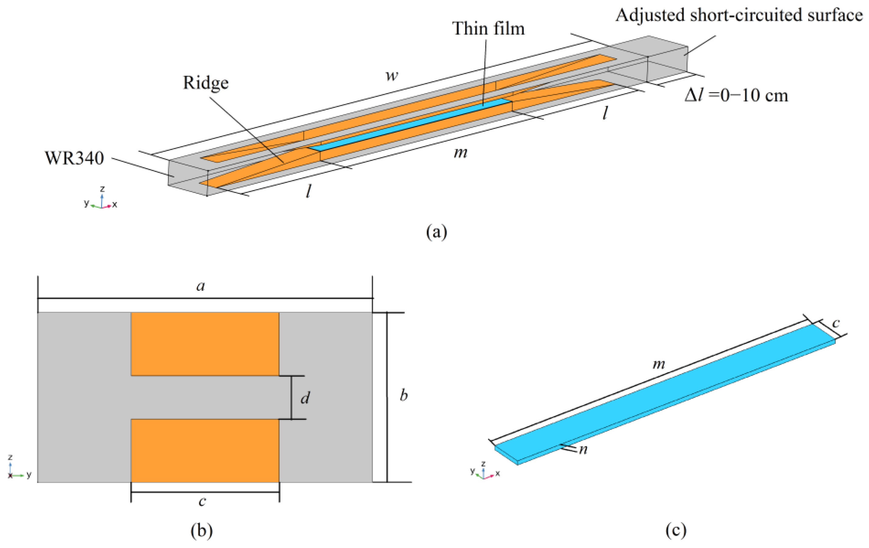
Based on Equation (7), a 3D microwave heating model is built in COMSOL Multiphysics 5.6, as shown in Figure 3, which is composed of a symmetrical structure of a double-ridged waveguide and a thin film placed on the bottom ridge. The detailed parameters are shown in Table 1.

2.3. Governing Equations

In the simulation, the microwave heating of the thin films is a process of multiphysics coupling of the electromagnetic field and thermal field. The electromagnetic field distribution can be solved by Maxwell’s equations [33] as follows:
× H = J c + D t
× E = B t
B = 0
D = ρ e
where H is the magnetic field strength, J c is the conductive current density, D is the electric displacement vector, E is the electric field strength, B is the magnetic induction strength, ρ e is the free charge density, and is the Hamiltonian. According to Maxwell’s equations, the Helmholtz equation can be further derived [34] as follows:
× u r 1 ( × E ) k 0 2 ( ε r j σ ω ε 0 ) E = 0
where k 0 is the wave number in free space, σ is the electrical conductivity, ε r is the relative permittivity, and ε 0 is the permittivity in vacuum. After calculating the electric field distribution inside the waveguide, the electromagnetic power loss Q e , and temperature T at various places inside the waveguide can be obtained by the following:
Q e = 1 2 ω ε 0 ε r E 2
ρ m C p T t k m 2 T = Q = Q e
where ε r is the imaginary part of the relative permittivity of the heated film, ρ m is the density of the heated film, C p is the specific heat capacity of the heated film, Q is the heat source, and k m is the heating coefficient of the heated film.

2.4. Input Parameters and Boundary Conditions

In the simulation with COMSOL Multiphysics, the transverse wave with T E 10 mode is used. Except for the incident port of the electromagnetic wave, the remaining surfaces of the cavity are perfect electrical conductors. Therefore, the boundary condition of the electric field on the boundary between air and metal satisfies
n × E = 0
where n is the unit normal vector. It can be seen that the tangential components of the electric fields are vanishing at the surface of the cavity.
In terms of thermodynamics, it heat dissipation exists in heated film, air, and ridge, and the boundary condition of heat transfer satisfies
k m T n + h ( T T e x t ) = 0
where h is the heat transfer coefficient, and T e x t is the temperature of the air and ridge with the value of 30 °C. The heat transfer coefficient between air and rubber is 10 W / m 3 · K , and the heat transfer coefficient between ridge and rubber is 55 W / m 3 · K .
In this model, the operating frequency is 2.45 GHz, and the waveguide is filled with air. The input power is set to 250 W, and the initial temperature is 30 °. Related input parameters of the simulation are shown in Table 2.

3. Results and Discussions

3.1. Transmission Performance

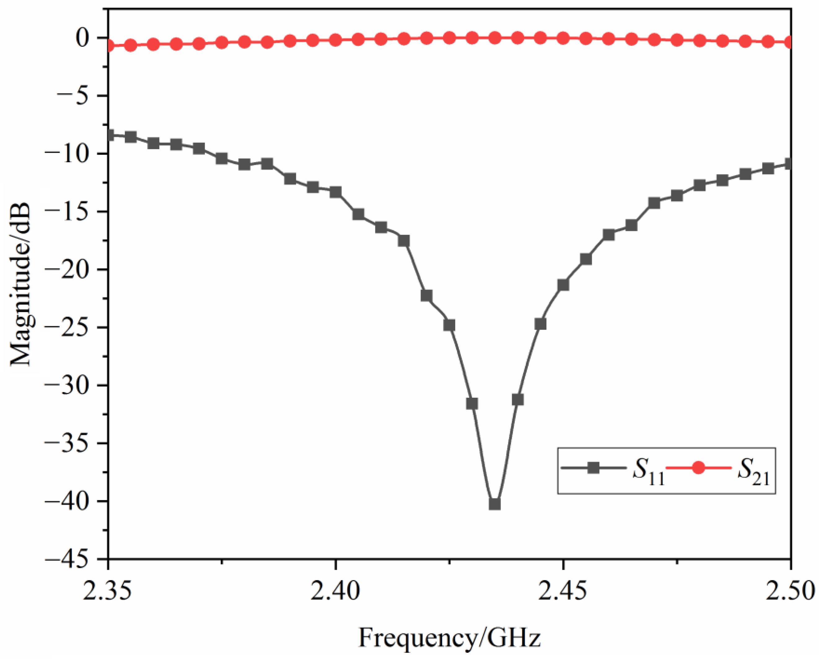
After the input parameters are determined, the S-parameters of the double-ridged waveguide are S11 and S21, as shown in Figure 4. S11 represents the reflection coefficient at port 1 when port 2 is terminated in a matched load, and S21 represents the transmission coefficient from port 1 to port 2. It is worthy of note that the short-circuited surface in Figure 3 is set as a wave port. It can be seen that in the range of 2.41–2.47 GHz, S11 is less than −15 dB, and S21 is approaching 0 dB. At a frequency of 2.45 GHz, S11 is about −21 dB, which is suitable for highly efficient heating.
In order to compare the electric field distribution between the double-ridged and the conventional waveguides, the electric field distribution inside a WR340 and the double-ridged waveguide in the x–y cross-section is shown in Figure 5. It can be seen that the electric field inside the double-ridged waveguide is mainly distributed in the gap between the two ridges, while the electric field in other areas is very small, which is also in agreement with the electric field distribution in the standing wave state. On the other hand, the electric field inside the WR340 is much smaller. It can be concluded that the structure can, indeed, concentrate the electric field energy between the ridges, which is nearly 2.5 times that in a conventional WR340 waveguide.

3.2. Experimental Validation

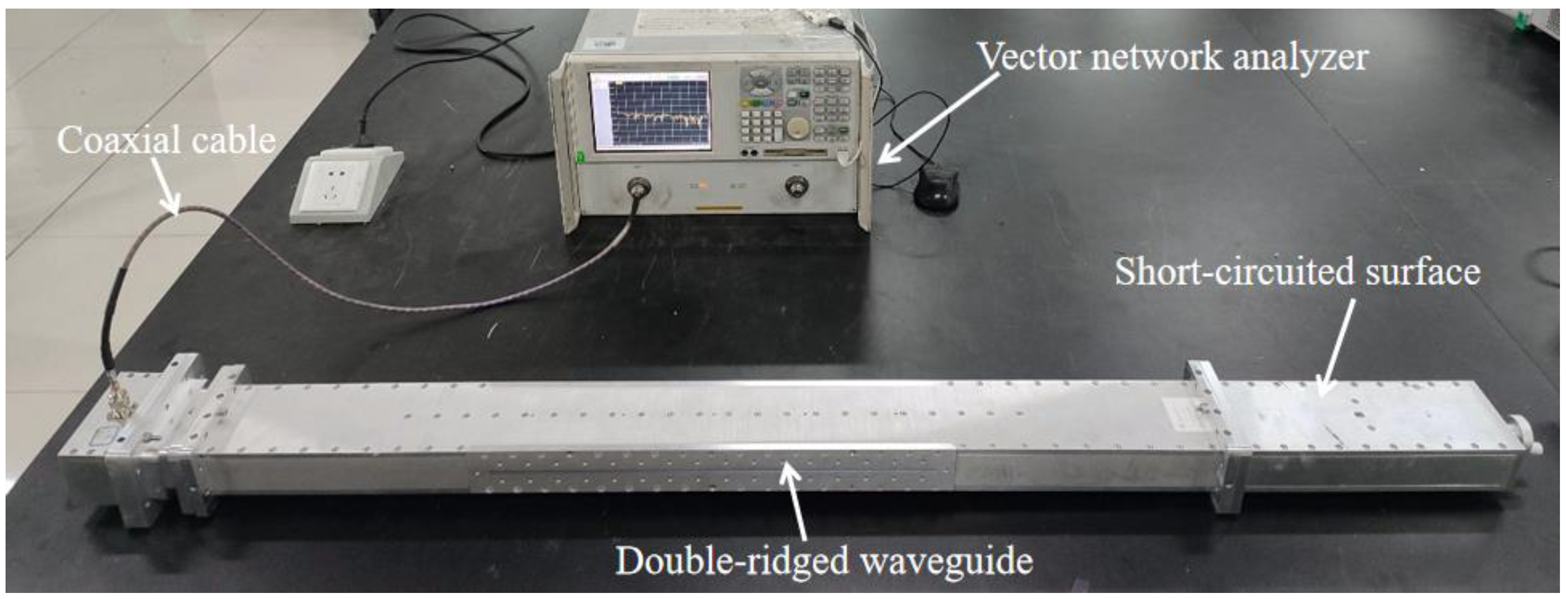
To verify the model, experiments are carried out based on the simulated results. The photograph of the experimental system is shown in Figure 6. The solid-state generator is used as the microwave source. The circulator and water load are used to protect the solid-state generator by absorbing reflected power. The double-ridged waveguide is used to heat the thin film, which is inserted into the double-ridged waveguide through the slots on both sides of the waveguide. For the purpose of preventing leakage of the microwave, the slots are sealed with copper foil tape. The adjusted short-circuited surface is used to change the position of the standing wave, and the film temperature is measured by the optic fiber thermometer and the thermal imager. The material of the heated film is nitrile butadiene rubber (NBR). The input power is set to 250 W, and the heating time is set to 180 s.
To heat the thin films efficiently, the short-circuited surface is adjusted to the best position by measuring the S11 of the double-ridged waveguide using the Vector Network Analyzer (N5230A, Agilent Technologies, Palo Alto, CA, USA) when the heated film is placed in the double-ridged waveguide. The photograph of the adjusting short-circuited surface is given in Figure 7, and the Δ l in Figure 3 is selected as 3.2 cm.
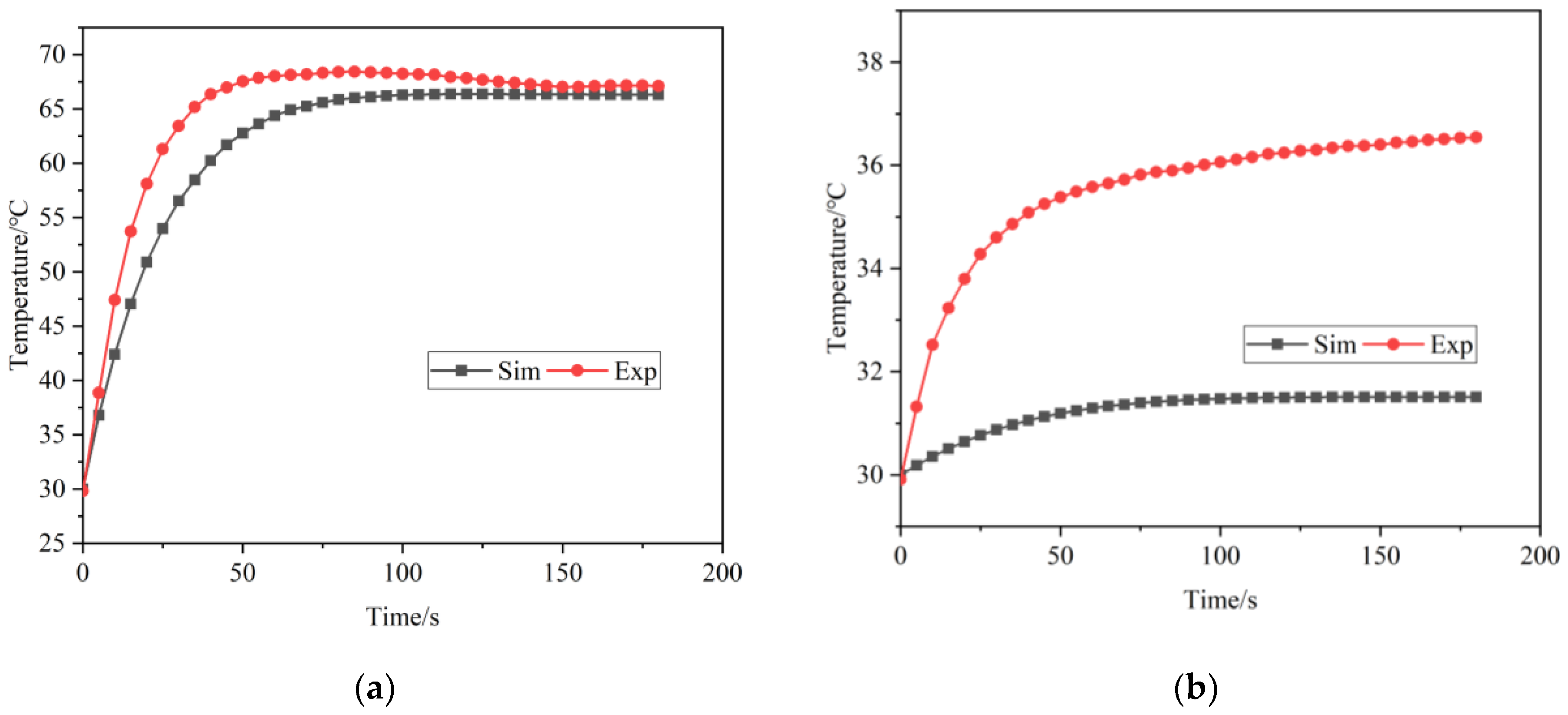
After setting the value of Δ l at 3.2 cm, the heating experiment is carried out. Since the end of the waveguide is shortened, the standing is formed. Therefore, the temperature rise curves in the node and antinode areas of the electric field are measured, as shown in Figure 8 and Figure 9a. Marked red is the node area, and yellow is the antinode area of the electric field. It is clearly seen that the experiment results have a good accordance with the simulated results. The surface temperature distribution of the thin film is also measured by the thermal imager after 180 s. It can be seen that the trends of the simulated and experimental temperature distributions are consistent, but there is a huge difference in value between the simulation and the experiment, mainly because it takes about 10 s to move the film out of the waveguide, and the heat conduction between the film and air leads to a fast cooling of the film. However, based on the real-time measurement results shown in Figure 8 and the surface temperature distributions shown in Figure 9, the simulation model is valid.

3.3. Sensitivity Analysis

3.3.1. Effect of the Working State on Heating Performance

The double-ridge waveguide has two working states. The first is the traveling-wave state, and the other is the standing-wave state. A traveling wave is a transmission state on a transmission line where the electric field changes exponentially along the propagation direction. The traveling wave moves towards the terminal of the transmission line with time. A standing wave refers to a distribution state formed along a transmission line by two waves with the same frequency and opposite transmission directions. In the standing wave, the positions of nodes and antinodes are always the same, but the instantaneous value changes with time. The electric field distributions of two working states in the gap between two ridges are shown in Figure 10.
The working state is dependent on the boundary condition on the surface at the end of the waveguide. The standing-wave state is set up with short-circuited surface, and the traveling-wave state is set up with a matched load. The detailed heating performances of the two working states after 180 s of heating are shown in Table 3.
In Table 3, the COV is used to analyze the uniformity of heating of an object, which is expressed as follows:
C O V = i = 1 n ( T i T a ) 2 T a T 0
where T i is the temperature of each point on the film, T a is the average temperature of the film, and T 0 is the initial temperature of the film. It is obvious that the traveling-wave state has better heating uniformity than the standing-wave state, but its heating efficiency is much lower.

3.3.2. Effect of the Material Permittivity on Heating Performance

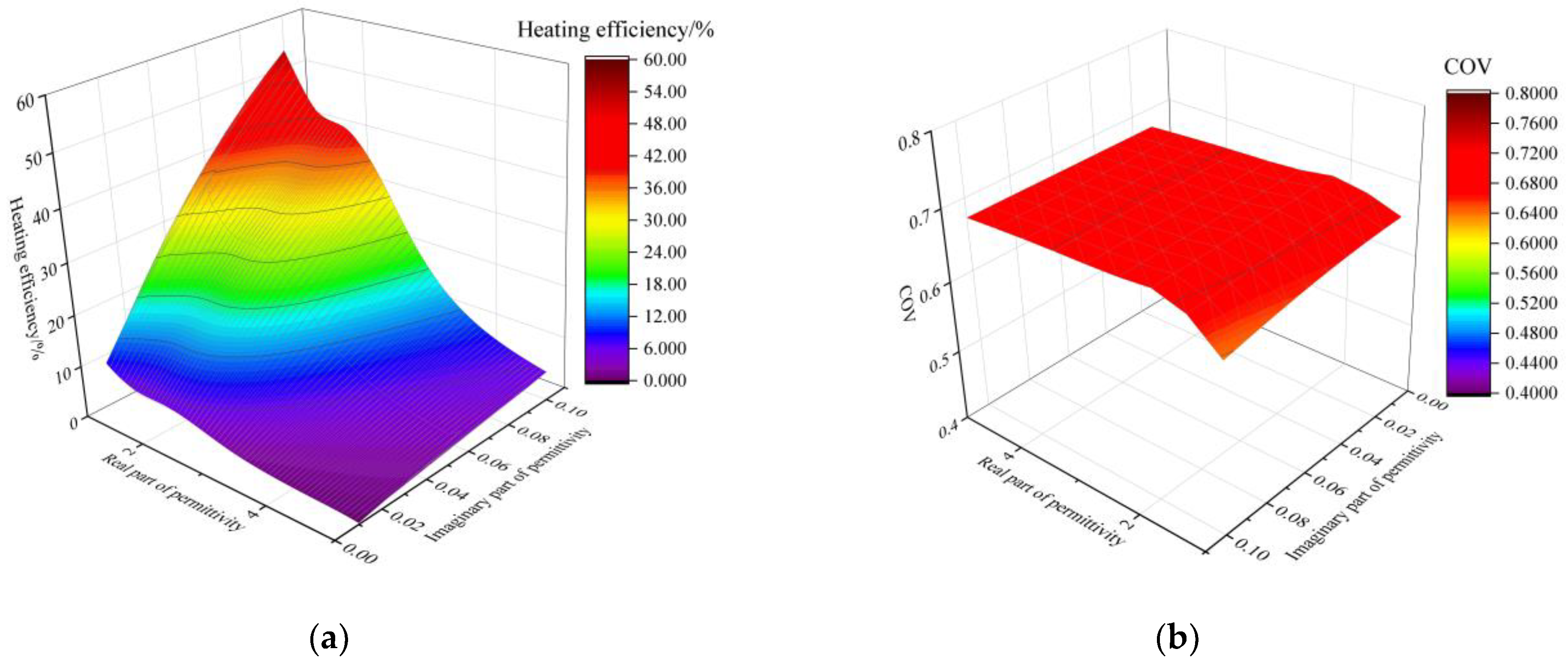
The effect of material permittivity on heating efficiency and uniformity is also carried out. The film is fixed with a thickness of 0.8 mm, and the short-circuited surface is not adjusted. The real part of relative permittivity is changed from 1 to 5 with an interval of 0.5, and the imaginary part of relative permittivity varies from 0.01 to 0.1 with an interval of 0.01. The heating efficiency with different relative permittivities is shown in Figure 11a, and the heating uniformity is shown in Figure 11b, from which it can be observed that the heating efficiency increases with the rise of the imaginary part. Besides, as seen in Figure 11b, the COV is stable in the range of 0.6–0.7, indicating that the heating uniformity has an inconspicuous relationship to the material permittivity.

3.3.3. Effect of the Film Thickness on Heating Performance

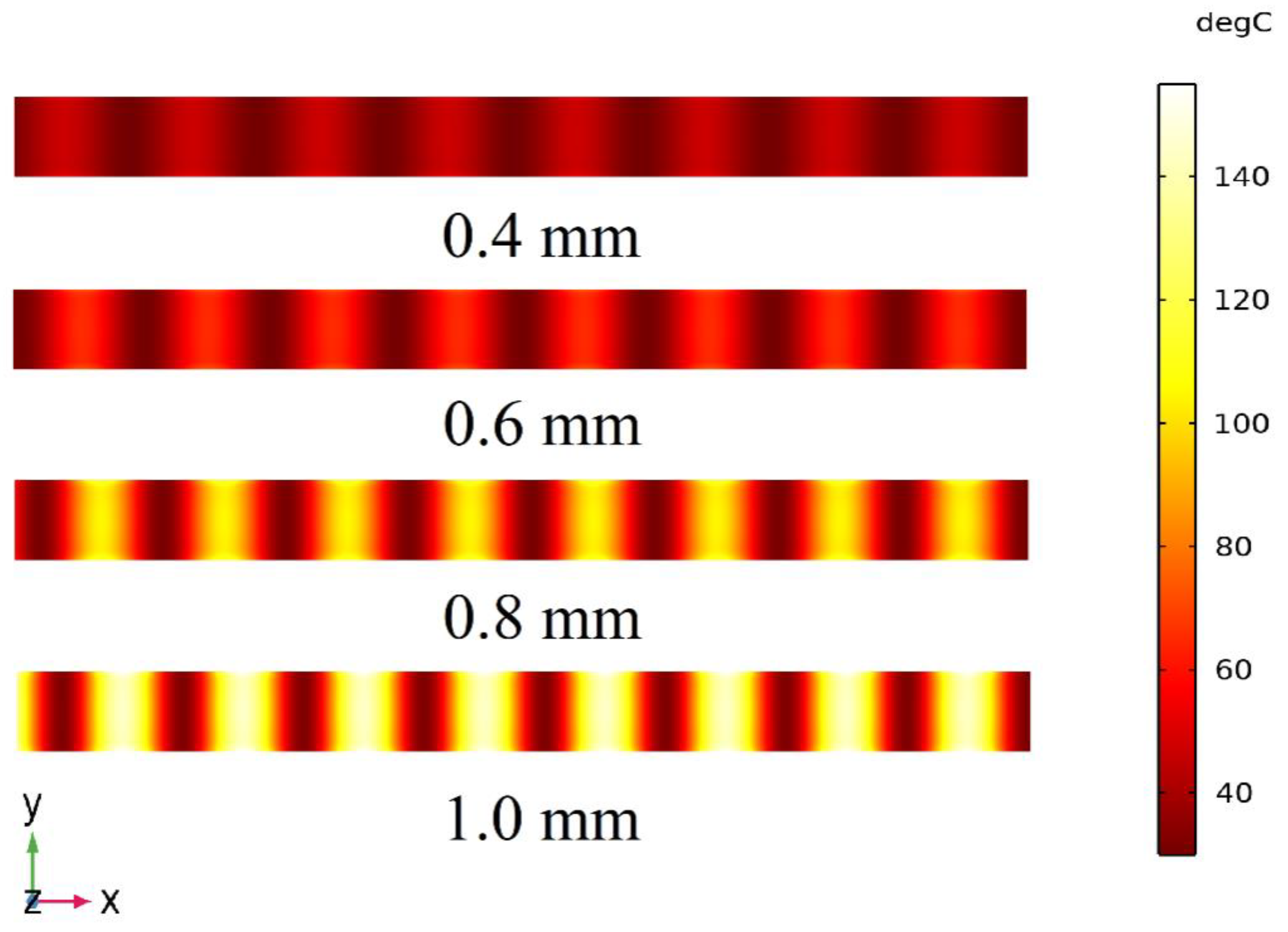
For practical heating, the film with different thicknesses was processed. Therefore, the effect of the thickness on the heating performance has also been investigated. The distance between the two ridges was fixed at 3 mm, and the film thickness varied from 0.4 mm to 1.0 mm. To ensure the best heating efficiency, the Δ l was adjusted to 8 cm. These films were heated for 180 s with the microwave power of 250 W. The temperature distribution is shown in Figure 12, and the detailed heating performance is in Table 4. It can be seen that the heating efficiency improves with increasing thickness. On the other hand, the COV stays almost the same, when the thickness ranges from 0.4 mm to 1.0 mm.

3.3.4. Effect of the Distance between Two Ridges on Heating Performance

The distance between two ridges is also a key factor influencing the heating performance. In order to discuss the heating performance, the thickness of the film is fixed at 0.8 mm, and the Δ l is at 1 cm. The distance between the two ridges varies from 1 cm to 7 cm. The electric field calculations, performed by varying the distance between two ridges, are shown in Figure 13. It can be seen that when the distance increases, the ability to enhance the electric field is weakened. The detailed heating performance is shown in Table 5. With the distance increase, the average temperature rise of the film shows a downward trend since the electric field between the two ridges gradually decreases, as shown in Figure 13. Meanwhile, the heating uniformity is nearly stable at different distances.

4. Conclusions

In this paper, a double-ridged waveguide with good reflection and transmission coefficients is designed; the S11 is less than −15 dB, and the S21 is approaching 0 dB in the frequency range of 2.41–2.47 GHz. The electric field strength of the film located in the proposed waveguide is close to 40 kV/m with a microwave power of 250 W at 2.45 GHz, which is about 2.5 times that in WR340. Furthermore, a multiphysics model coupled with electromagnetic field and heat transfer in solid is built. The simulation results show that the heating performance of the proposed waveguide is 35.0 times that of a conventional rectangular waveguide. Compared with the experimental results, the correctness of the proposed model is verified. The standing-wave state can provide a much stronger electric-field distribution than the traveling-wave state. On the other hand, the permittivity of material has a great influence on heating efficiency but little influence on heating uniformity. Meanwhile, the film thickness and the distance between the two ridges also have little influence on the heating uniformity. In practical situations, to improve the heating efficiency, the wave state, the permittivity of a material, the film thickness, and the distance between two ridges need to be discussed further. This paper may provide a possible way to achieve high-efficient rubber vulcanization.

Author Contributions

Q.W.: Writing—original draft; H.C.: numerical simulations; Z.H.: validation; Y.Y.: resources; H.Z.: review and editing; T.H.: review and editing, methodology. All authors have read and agreed to the published version of the manuscript.

Funding

This research was funded by the National Natural Science Foundation of China (62001398), the Key Technology Project of Shunde District (2130218002514), and the Nature Science Foundation of Sichuan Province (2022NSFSC0562).

Institutional Review Board Statement

Not applicable.

Informed Consent Statement

Not applicable.

Data Availability Statement

Not applicable.

Conflicts of Interest

The authors declare no conflict of interest.

References

  1. Tang, Z.; Zhang, S.; Hong, T.; Zhu, H.; Huang, K. Frequency-selected microwave heating: Its mathematical physics basis and characteristics. Int. J. RF Microw. Comput. 2020, 30, e22131. [Google Scholar] [CrossRef]
  2. Chen, J.; Li, L.; Chen, G.; Peng, J.; Srinivasakannan, C. Rapid thermal decomposition of manganese ore using microwave heating. J. Alloy. Compd. 2017, 699, 430–435. [Google Scholar] [CrossRef]
  3. Ekezie, F.G.C.; Sun, D.W.; Han, Z.; Cheng, J.H. Microwave-assisted food processing technologies for enhancing product quality and process efficiency: A review of recent developments. Trends Food Sci. Technol. 2017, 67, 58–69. [Google Scholar] [CrossRef]
  4. Beckler, B.; Cowan, A.; Farrar, N.; Murawski, A.; Robinson, A.; Diamanduros, A.; Scarpinato, K.; Sittaramane, V.; Quirino, R.L. Microwave Heating of antibody-functionalized carbon nanotubes as a feasible cancer treatment. Biomed. Phys. Eng. Expr. 2018, 4, 045025. [Google Scholar] [CrossRef]
  5. Chen, H.L.; Li, T.; Liang, Y.; Sun, B.; Li, Q.L. Experimental study of temperature distribution in rubber material during microwave heating and vulcanization process. Heat Mass Transf. 2017, 53, 1051–1060. [Google Scholar] [CrossRef]
  6. Vakhin, A.V.; Khelkhal, M.A.; Tajik, A.; Ignashev, N.E.; Krapivnitskaya, T.O.; Peskov, N.Y.; Glyavin, M.Y.; Bulanova, S.A.; Slavkina, O.V.; Schekoldin, K.A. Microwave Radiation Impact on Heavy Oil Upgrading from Carbonate Deposits in the Presence of Nano-Sized Magnetite. Processes 2021, 9, 2021. [Google Scholar] [CrossRef]
  7. Murzakhanov, F.; Ponomarev, A.; Khelkhal, M.A.; Amziane, O.; Vakhin, A.V.; Gafurov, M. Conventional and high-field pulsed EPR experimental studies on Bazhenov oil formation under the influence of 50 Hz electromagnetic field. Fuel 2023, 334, 126580. [Google Scholar] [CrossRef]
  8. Sun, J.; Wang, W.; Yue, Q. Review on microwave-matter interaction fundamentals and efficient microwave-associated heating strategies. Materials 2016, 9, 231. [Google Scholar] [CrossRef] [Green Version]
  9. Asami, S. Surface Drying by High Frequency Dielectric and Microwave Heating. J. Surf. Finish. Soc. Jpn. 2015, 66, 305–310. (In Japanese) [Google Scholar] [CrossRef] [Green Version]
  10. Antony, P.; Paoloni, F. Heating of lossy films on a metal surface using a dielectric loaded T-septum waveguide. J. Microw. Power Electromagn. Energy 1992, 27, 112–116. [Google Scholar] [CrossRef]
  11. Song, Z.; Jing, C.; Yao, L.; Zhao, X.; Wang, W.; Mao, Y.; Ma, C. Microwave drying performance of single-particle coal slime and energy consumption analyses. Fuel Process Technol. 2016, 143, 69–78. [Google Scholar] [CrossRef]
  12. Chen, H.; Li, T.; Li, K.; Li, Q. Experimental and numerical modeling research of rubber material during microwave heating process. Heat Mass Tran. 2018, 54, 1289–1300. [Google Scholar] [CrossRef]
  13. Erchiqui, F.; Kaddami, H.; Dituba-Ngoma, G.; Slaoui-Hasnaoui, F. Comparative study of the use of infrared and microwave heating modes for the thermoforming of wood-plastic composite sheets. Int. J. Heat Mass Tran. 2020, 158, 119996. [Google Scholar] [CrossRef]
  14. Huang, K.; Li, J.; Zhang, Y. Research on Dry Microwave Heating Infectious Aerosols or Droplets on Respirators. IEEE Trans. Microw. Theory Technol. 2021, 69, 4246–4255. [Google Scholar] [CrossRef]
  15. Dębowski, M.A. Low temperature microwave processing of silicone resin coatings containing microwave susceptors. Surf. Coat. Technol. 2017, 320, 13–17. [Google Scholar] [CrossRef]
  16. Sastry, S.K.; Palaniappan, S. The temperature difference between a microorganism and a liquid medium during microwave heating. J. Food Process Pres. 1991, 15, 225–230. [Google Scholar] [CrossRef]
  17. Clark, D.E.; Folz, D.C.; West, J.K. Processing materials with microwave energy. Mater. Sci. Eng. A 2000, 287, 153–158. [Google Scholar] [CrossRef]
  18. Leclerc, P.; Doucet, J.; Chaouki, J. Development of a microwave thermogravimetric analyzer and its application on polystyrene microwave pyrolysis kinetics. J. Anal. Appl. Pyrol. 2018, 130, 209–215. [Google Scholar] [CrossRef]
  19. Huang, K.M.; Lin, Z.; Yang, X. Numerical simulation of microwave heating on chemical reaction in dilute solution. Prog. Electromagn. Res. 2004, 49, 273–289. [Google Scholar] [CrossRef] [Green Version]
  20. Liao, Y.H.; Zhu, H.C.; Huang, K.M. Fast algorithm for electromagnetic pulse heating on dispersive medium. Int. J. Appl. Electromagn. Mech. 2016, 50, 275–282. [Google Scholar] [CrossRef]
  21. Huang, K.M.; Liao, Y.H. Transient power loss density of electromagnetic pulse in debye media. IEEE Trans. Microw. Theory Technol. 2014, 63, 135–140. [Google Scholar] [CrossRef]
  22. Hong, K.; Fu, W.; Guang, M.; Zhang, Y.; Li, B. Microwave heating performances of low density polyethylene (LDPE) plastic particles. J. Anal. Appl. Pyrol. 2021, 160, 105356. [Google Scholar] [CrossRef]
  23. Bleackley, W.J.; Vankoughnett, A.L.; Wyslouzil, W. Ridged waveguide microwave applicators. J. Microw. Power 1972, 7, 23–28. [Google Scholar] [CrossRef]
  24. El-Sayed, E.D.M.; Hashem, A.M. Wave propagation in rectangular waveguides with symmetrically placed tapered ridges. J. Microw. Power 1984, 19, 35–46. [Google Scholar] [CrossRef]
  25. El-Sayed, E.D.M.; Hashem, A.M. Ridged waveguide applicators for uniform microwave heating of sheet materials. J. Microw. Power 1984, 19, 111–117. [Google Scholar] [CrossRef]
  26. Liu, F.; Turner, I.; Siores, E.; Groombridge, P. A numerical and experimental investigation of the microwave heating of polymer materials inside a ridge waveguide. J. Microw. Power Electromagn. Energy 1996, 31, 71–82. [Google Scholar] [CrossRef]
  27. Zhou, P.; Yang, X.; Huang, K.; Jia, G. Microwave-Assisted Continuous-Flow Reactor Based on a Ridged Waveguide. Chem. Eng. Technol. 2015, 38, 1334–1339. [Google Scholar] [CrossRef]
  28. Helszajn, J.; Caplin, M. Impedance and propagation in ridge waveguide. Microw. Eng. Eur. 1997, 49–50. [Google Scholar]
  29. Hradecký, Z.; Mazánek, M. Nonstandard Double Ridged Waveguide Mode Study. Available online: https://www.researchgate.net/profile/M-Mazanek/publication/266584704_NONSTANDARD_DOUBLE_RIDGED_WAVEGUIDE_MODE_STUDY/links/54e253c50cf2c3e7d2d37564/NONSTANDARD-DOUBLE-RIDGED-WAVEGUIDE-MODE-STUDY.pdf (accessed on 10 October 2022).
  30. Marcuvitz, N. Waveguide Handbook; IET Digital Library: Hertfordshire, UK, 1986. [Google Scholar]
  31. Hoefer, W.J.; Burton, M.N. Closed-form expressions for the parameters of finned and ridged waveguides. IEEE Trans. Microw. Theory Technol. 1982, 30, 2190–2194. [Google Scholar] [CrossRef]
  32. Dang, Z.; Zhu, H.F.; Huang, J.; He, H.D. An ultra-wideband power combining in ridge waveguide for millimeter wave. IEEE Trans. Microw. Theory Technol. 2020, 68, 1376–1389. [Google Scholar] [CrossRef]
  33. Geedipalli, S.S.R.; Rakesh, V.; Datta, A.K. Modeling the heating uniformity contributed by a rotating turntable in microwave ovens. J. Food Eng. 2007, 82, 359–368. [Google Scholar] [CrossRef]
  34. Lin, B.Q.; Li, H.; Dai, H.M.; Zhu, C.J.; Yao, H. Three-dimensional simulation of microwave heating coal sample with varying parameters. Appl. Therm. Eng. 2016, 93, 1145–1154. [Google Scholar]
  35. Xing, K. Study on Heat Transfer Characteristics of Rubber Vulcanization with Cords by Microwave Heating. Master’s Thesis, Qingdao University of Science and Technology, Qingdao, China, 2017. [Google Scholar]
  36. Zhu, S.L. Investigation on Heat Transfer Characteristics and Temperature Control of Rubber in Microwave Vulcanization Process. Ph.D. Thesis, Qingdao University of Science and Technology, Qingdao, China, 2020. [Google Scholar]
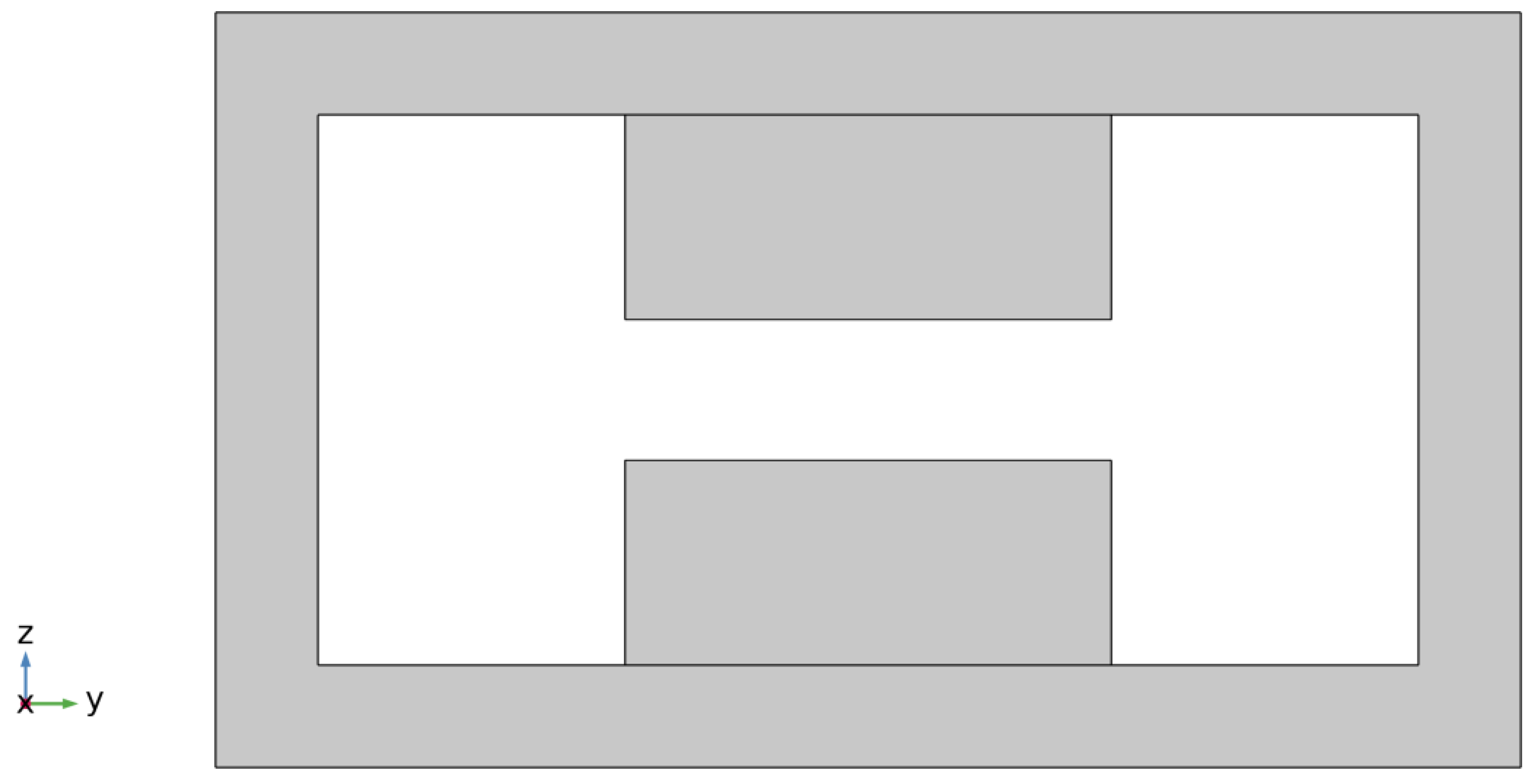
Figure 1. The cross-section of a double-ridged waveguide.
Processes 11 00145 g001
Figure 2. The equivalent circuit of the double-ridged waveguide.
Processes 11 00145 g002
Figure 3. Geometry of 3D simulation model. (a) 3D geometry of the double-ridged waveguide; (b) The structure of the double-ridged waveguide in the y–z plane; (c) The thin film.
Processes 11 00145 g003
Figure 4. The S-parameters of the double-ridged waveguide.
Processes 11 00145 g004
Figure 5. The electric field distribution in the conventional waveguide and double-ridged waveguide in the cross-section of z = 0 mm without load. (a) WR340; (b) Double-ridged waveguide.
Processes 11 00145 g005
Figure 6. The photograph of the experimental system.
Processes 11 00145 g006
Figure 7. The photograph of adjusting short-circuited surface by a vector network analyzer.
Processes 11 00145 g007
Figure 8. The temperature rise curves of the thin film. (a) The antinode area of the electric field; (b) The node area of the electric field.
Processes 11 00145 g008
Figure 9. The temperature distribution of the film in the x–y plane. (a) Simulation; (b) Experiment.
Processes 11 00145 g009
Figure 10. The electric field distribution of the traveling-wave state and the standing-wave state in the x–y plane. (a) Traveling-wave state; (b) Standing-wave state.
Processes 11 00145 g010
Figure 11. The 3D surface graphs. (a) Heating efficiency; (b) COV.
Processes 11 00145 g011
Figure 12. The temperature distribution of the films in the x–y plane.
Processes 11 00145 g012
Figure 13. The electric field distribution in the cross-section of z = 0.4 mm.
Processes 11 00145 g013
Table 1. The detailed parameters of the double-ridged waveguide. (unit: mm).
abcdmlwn
86.3643.1838348026011000.8
Table 2. Related input parameters of the simulation.
PropertyDomainValueUnitSource
Relative permittivityThin film
Air
2.17–0.05 × j
1
-
-
Measurement
-
Relative permeabilityThin film
Air
1
1
-
-
[35]
-
ConductivityThin film
Air
0
0
S/m[35]
-
Heat capacity at constant pressureThin film1671.8 J / ( kg · K ) [36]
DensityThin film1309.1 Kg / m 3 [36]
Heat conductivity coefficientThin film0.25 W / ( m · K ) [36]
Table 3. The heating performance of the two working states.
Working StateCOVHeating Efficiency/%
Traveling wave0.3067.12
Standing wave0.69023.29
Table 4. The heating performance of different film thicknesses.
Thickness/mmCOVHeating Efficiency/%
0.40.6944.68
0.60.7039.34
0.80.70419.18
1.00.68729.11
Table 5. The heating performance with different distances between the ridges.
Distance/mmCOVHeating Efficiency/%
10.64452.14
30.67417.22
50.6888.79
70.6714.98
Disclaimer/Publisher’s Note: The statements, opinions and data contained in all publications are solely those of the individual author(s) and contributor(s) and not of MDPI and/or the editor(s). MDPI and/or the editor(s) disclaim responsibility for any injury to people or property resulting from any ideas, methods, instructions or products referred to in the content.