Abstract
TA19 titanium alloy is a novel medium-temperature, high-strength titanium alloy widely used in the aerospace industry, and its welding performance is very important for the manufacturing of structural parts. In this study, TA19 titanium alloy was connected by inertial friction welding (IFW). After welding, the microstructural and alloying elements of the IFW joints were investigated; the results showed that the microstructures of each zone of the IFW joint were different, and accumulations of the β-stable element Mo were only observed in the base metal (BM) and the heat-affected zone (HAZ). Tensile tests were performed using specially designed specimens with circular grooves to obtain the axial mechanical properties of different zones of IFW joints. The stress–strain curves and tensile fractures of the different specimens were analyzed; the results showed that the tensile strength of the welded joint increased, but the plasticity decreased from BM to WZ.
1. Introduction
Non-ferrous metal titanium, since it was introduced in industrial production in the 1940s, has been widely used in the chemical, military, medicine, aerospace, and other industries, due to its advantages of low density, high specific strength, low elastic modulus, good corrosion resistance, and heat resistance [1,2,3,4]. TA19 titanium alloy (Ti-6Al-2Sn-4Zr-2Mo) is a typical near-α-type titanium alloy, with the advantages of traditional titanium alloy, but also exhibits good thermal strength and weldability, high hardness, and enhanced toughness [5,6]. TA19 has been successful in providing creep resistance up to operating temperatures of 550 ℃; it is a titanium alloy with excellent comprehensive properties [7]. It is currently widely used in the manufacturing of aero-engine blades, compressor blade discs, rotors, and other key components [8,9].
Alloys need to be joined, especially welded, before they can be put into industrial production; titanium alloys have high strength, high melting points, low thermal conductivity, and other useful characteristics. Contemporary welding methods of titanium alloy include brazing, laser welding, and friction stir welding [10,11,12]. The welded joints obtained through the traditional welding method are relatively wide, and the strength of the joint part is lower than that of the base metal. Inertial friction welding (IFW), compared with the traditional welding methods mentioned above, is a solid-state welding technology demonstrating many advantages, e.g., its high quality, high efficiency, environmental friendliness, low heat input, small deformation, and narrow welding seam. IFW has been proven to be a suitable welding method for titanium alloy and has been widely used in aerospace and other high-tech fields [13,14].
In the process of IFW, the weldment moves in relative friction under the action of axial pressure, and the heat generated by friction softens the metal at the welding interface to form a plastic deformation layer. At high temperatures, interfacial material—rather than melting—is thermoplastic; thus, IFW can effectively avoid common defects in fusion welding, such as oxidation slag, incomplete fusion, fusion, solidification cracking, etc. [13,14,15]. In addition, because the two weldments are in full contact, with the increase in the contact area, the cores and edges of the welded joints will be relatively uniform, and the mechanical properties are almost consistent. IFW is relatively suitable for rotor and shaft-type workpiece welding due to these characteristics. Turner et al. performed a simulation analysis of inertial friction welding process parameters and concluded that the initial rotational speed parameter (assuming that sufficient energy is provided by the flywheel) has little effect on the quality of the joint [16]. Jeong et al. investigated the tensile properties of inertia friction welded joints of SFCMV1 (SANYO special steel, high strength low alloy Cr-Mo steel), where the fracture location of the joint was the base metal, and concluded that the selection of a suitable post-weld heat treatment could slightly improve the tensile properties [17]. Zhao et al. performed inertial friction welding of IMI834/Ti6246 on dissimilar materials and concluded that the inertial friction welding forms the fine microstructure in the welding seam of IMI834/Ti6246 dual titanium alloy, with coarse microstructures of heat-affected zones on both sides [18].
Li and Wu et al. studied the microstructural and mechanical properties of IFW joints of titanium alloys TC21 and TA19 [19,20], concluding that the tensile strength of the weld zone is higher than that of the base metal zone. However, neither of these studies analyzed the elemental composition of each zone of the IFW joints, and the fracture forms of different zones of IFW joints have not been compared. If fractures formed in the weld zone are closer to brittle fractures, even if the tensile strength of the weld zone is stronger than that of the base metal, the risk of sudden brittle fractures would still exist in the weld zone. Ji et al. investigated the fracture toughness of IFW joints of Ti17 in each zone and concluded that the toughness of the joint gradually decreased from the BM to the WZ, and the fracture morphology from the BM to the WZ gradually changed from ductile fracture to brittle fracture [21]. In this study, the microstructure and tensile properties of TA19 inertia friction welding joints were further investigated in depth. The reasons why the large β-phase disappears in the weld zone are explained from the perspective of alloy element redistribution. In addition, a special test method was utilized to conclude that the tensile strength of TA19 IFW joints gradually increases from BM to WZ, but the plasticity gradually decreases. This conclusion was also combined with the microstructure and surface morphology of the tensile fracture to explain the tensile properties of TA19 IFW joints from a new and comprehensive perspective.
2. Materials and Methods
The material used in IFW experiments was typical near-α-type titanium alloy TA19 with a duplex microstructure, achieved by 950 °C forging. After forging, the alloy was treated by annealing at 850 °C for 2 h. The inner diameter of the TA19 titanium alloy ring used in the experiment was 65 mm and the outer diameter was 135 mm. The shape and size are shown in Figure 1, and the chemical composition of the TA19 alloy is detailed in Table 1. The welding processes of two ring samples of TA19 alloy were performed using an HSMZ-130 axial and radial inertia friction welding machine designed by Harbin Welding Institute Limited Company (China, Harbin). After several IFW tests on titanium alloy, Li et al. finally determined the welding parameters of the titanium alloy inertial friction welded joint successfully [19], and this study referred to its welding parameters: the initial welding rotating speed was 500 rpm, the moment of inertia was 388 kg·m2, and the upsetting pressure was 102 MPa. After welding, the solution treatment of the TA19 weldment was carried out at 595 °C for 8 h.
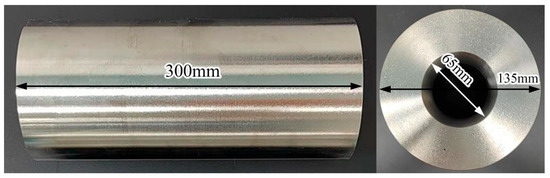
Figure 1.
Dimensions of TA19 titanium alloy ring.

Table 1.
Chemical composition of TA19 alloy, wt.%.
After welding, IFW joints (length of 70 mm) were taken; then, the welding flash was cut off, and there were no radial or axial cracks at the joint, as shown in Figure 2a. The IFW joints after cutting included all welding zones and the weld zone was located in the middle. As shown in Figure 2b, the round bar test samples (diameter of 14 mm and length of 70 mm) were cut from the axial direction of the welded joint. The metallographic sample was acquired from bar specimens by cutting longitudinally along the axial center, after grinding, polishing, and etching by corrosive liquid with a ratio of 1% HF + 3% HNO3 + 96% H2O, the chemical corrosion time was 5 s and the corrosion temperature was room temperature. Dumbbell-shaped specimens were obtained by further machining the round bar specimens, which were then used for tensile tests; the sizes of the dumbbell-shaped specimens are shown in Figure 2c. Circular grooves were processed in the base metal (BM), thermomechanical-affected zone (TMAZ), and weld zone (WZ). When circular grooves are processed in three different zones, stress concentration will occur, leading to the priority of the tensile fracture. In this way, the relative tensile properties of these three areas can be obtained, and the tensile fracture can be observed. The sizes of specimens with circular grooves are also indicated in Figure 2c.
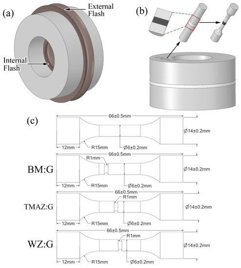
Figure 2.
Schematic diagram of the acquisition procedure for the experimental samples (a) IFW joints; (b) procedure for the processing samples; (c) specimen sizes.
The microstructures of the TA19 base metal and IFW joint were studied using a VHX-7000 optical metallographic microscope (OM) and SU8100 scanning electron microscope (SEM). Tensile tests were conducted at room temperature using a MTS-793 electro-hydraulic servo testing machine. For tensile tests, the loading rate was 1 mm/s and the change point of the extensometer was at a 3% strain. After the tensile test, OM and SEM were used to observe the tensile fracture.
3. Results and Discussion
Figure 3 shows the optical microstructure of each zone of the IFW joint. IFW joints are generally divided into the base metal (BM), heat-affected zone (HAZ), thermo-mechanical-affected zone (TMAZ), and weld zone (WZ) in the industry. In the IFW process, the conditions of thermal and mechanical forces on both sides (with WZ as the center) are similar, and it can be considered that the microstructure is symmetrically distributed with the welding interface as the center. Figure 3a shows the overall optical microscopic image of the IFW joint. It can be observed that the width of the WZ in the center was about 1.2 mm, the width of the TMAZ on both sides of the WZ was about 1.1 mm, the width of the HAZ on both sides of the TMAZ was about 900 mm, and BM was on both sides of the HAZ. Figure 3a indicates the width and location of each zone of the joint, and the exact width range of each zone was determined through high-magnification OM and SEM observations.
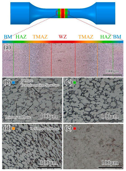
Figure 3.
Optical micrographs of the IFW joint: (a) overall IFW joint; (b) BM; (c) HAZ; (d) TMAZ; (e) WZ.
As shown in Figure 3b, the microstructure of the BM was a duplex microstructure composed of an equiaxed primary α-phase and β-transformation structure (lamellar structure composed of base β-phase and lath α-phase), in which the sizes of equiaxed primary α-phase grains ranged from 30 to 50 mm. As shown in Figure 3c, compared with the BM, the grain size of the primary α-phase of the HAZ was almost unchanged. However, under the same observation conditions with the optical metallographic microscope, the β-transformation structure observed in the HAZ was darker in color; the phenomenon indicated that the β-transformation structure of the HAZ changed compared with the BM.
As shown in Figure 3d, both the equiaxed primary α-phase and β-transformation structures of TMAZ were elongated due to mechanical forces. As shown in Figure 3e, the equiaxed primary α-phase and β-transformation structures of the WZ had completely disappeared, and the microstructures here were transformed into a completely new structure. From the above observation results, optical metallographic microscopy could observe the microstructure of the joint in a wide range, but some questions arose regarding the details: What is the difference between the β-transformation structures of the HAZ and the BM? What is the new microstructure of the WZ? To further determine the details of the microstructure in each zone, a scanning electron microscope (SEM) was used to increase the magnification for observation.
Figure 4 shows the microstructure of each zone of the IFW joint observed by scanning electron microscopy. As shown in Figure 4a, the BM is divided into the equiaxed primary α-phase and β-transformation structure, and the high-magnification microscopic image on the upper right shows that the β-phase in the base of the β-transformation structure is a solid solution structure, and the fine needle α-phase is solidly dissolved in it. As shown in Figure 4b, it can be seen that the equiaxed primary α-phase of the HAZ is almost unchanged by SEM, although the boundary of the β-transformation structure becomes blurred. The high-magnification microscopic image on the upper right shows that the β-transformation structure of the HAZ changes from a solid solution structure to an α + β fine lamellar structure. Due to the heat generated in the IFW process being transferred from the welding interface to HAZ by heat conduction, the temperature here reaches the α → α + β phase-transition temperature of TA19 [16,22], and the sharp temperature drop after IFW causes the microstructures to transform into the martensite α’ phase; a further post-weld heat treatment resulted in the decomposition of the martensitic α’ phase into an α + β equilibrium-state structure. Due to the sharp heating up and cooling down at the HAZ during IFW, it also only thermally affects the fine-needle α-phase in a solid solution, whereas the large-sized equiaxed primary α-phase is almost not thermally affected.
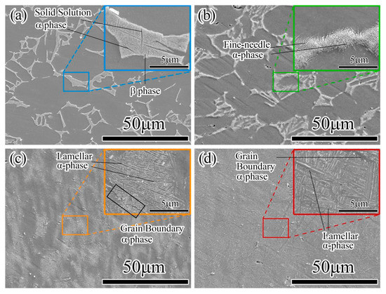
Figure 4.
SEM microstructure photographs of different zones: (a) BM; (b) HAZ; (c) TMAZ; (d) WZ.
As shown in Figure 4c, both the equiaxed primary α-phase and β-transformation structures of the TMAZ near the WZ are elongated, but the interior microstructure of the equiaxed primary α-phase remains unchanged, whereas the β-transformation is not only deformed but the internal microstructure is also changed. The high-magnification microscopic image in the upper right shows that the β-transformation structure at the TMAZ changes from solid solution to α + β lamellar structure, and there is a similar appearance of grain boundary α-phase here. The reason for the above-mentioned transformation of the microstructure is that the temperature of the TMAZ reaches near the β phase-transition temperature (950 ± 20 °C) during IFW [16], and there is a certain amount of plastic deformation, which causes dynamic recrystallization in the β-phase. The β-transformation structure was transformed into the martensite α’ phase due to the sharp temperature drop after IFW, and further post-weld heat treatment resulted in decomposition of the martensitic α’ phase into the α + β lamellar structure, whereas higher energy at the boundary preferentially induced α-phase precipitation here.
As shown in Figure 4d, there is a complete and severe dynamic recrystallization of the β-phase in the WZ, which leads to the generation of a very small recrystallized β-phase, and the results of Wu et al. and Wang et al. showed that the weld zone of inertia friction welding reaches 1200 °C during welding [20,23]. Combining the transformation of the microstructure and the results of the research by Wu et al. to determine that the temperature in the weld zone must have exceeded the TA19 β phase-transition temperature (950 ± 20 °C) during IFW, while the sharp temperature drop after welding causes the fine recrystallized β-phase to tangentially form martensite α’ [23], and there was significant plastic deformation. Further post-weld heat treatment resulted in the decomposition of the martensitic α’ phase into an α+β lamellar structure, while the higher energy at the boundary will have the α-phase preferentially precipitated here. The size of the α + β lamellar structure in the WZ is larger, and the grain boundary α-phase is wider compared with the TMAZ; the reason for the difference in microstructure between the two zones is that the deformation and heat storage at WZ has more distortion energy.
3.1. Elemental Analysis
Figure 5a–c show the chemical elemental compositions of different microstructures of the HAZ, TMAZ, and WZ obtained by EDS; Table 2 shows the elemental ratios of different test areas. Elemental analyses of the equiaxed α-phase and β-basic-phase in the HAZ were conducted separately, the results show that the eutectic β-phase stabilizing element Mo of the titanium alloy has zero content in the equiaxed α-phase and 10.9% in the β-basic phase. The eutectic β-stabilizing element Mo of the titanium alloy undergoes aggregation in the β-basic phase, indicating that the Mo element can still stabilize the large-size β-phase in the HAZ.
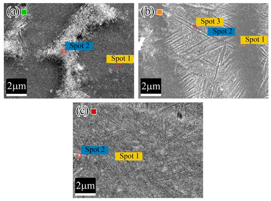
Figure 5.
EDS element analysis of different zones of IFW: (a) HAZ; (b) TMAZ; and (c) WZ.
Table 2.
Ratio of elements at different test zones in HAZ, TMAZ, and WZ.
Elemental analysis of the deformed equiaxed primary α-phase, the β-basic phase of the β-transformation structure, and the internal fine-needle α-phase was performed in the TMAZ. The content of the eutectic β-phase stabilizing element Mo in the deformed primary α-phase remained zero. However, the elemental content in the two regions selected for testing at the b-transformation structure was hardly different; the Mo elemental content, especially, was not elevated in these two regions either, which indicates that the Mo elements did not aggregate here, and the unaggregated Mo elements were also unable to stabilize the large β-phase at room temperature.
The microstructure of the WZ changed from a duplex microstructure in the BM to a fine α + β lamellar structure. The elemental composition of the two selected test areas in the WZ was almost the same, and the elemental content was similar to that of the original alloy, which indicated that the elemental redistribution occurred in WZ, and the homogeneous elemental distribution led to a homogeneous α + β lamellar structure, and unaggregated Mo elements were also unable to stabilize the large β-phase at room temperature.
The evolution of the elemental content of the different zones of the IFW joint can be explained by the following two aspects:
- The high mechanical forces and high heat input during IFW lead to severe plastic deformation of all the WZ and part of the TMAZ; a large amount of distortion energy is stored; and the redistribution of elements occurs during the occurrence of dynamic recrystallization.
- The sharp temperature drop after welding leads to the eutectic β-stable element Mo being fixed in situ, and no aggregation is formed. The post-welding heat treatment temperature is lower than the β-phase transformation temperature; thus, there is also no secondary diffusion of Mo elements.
3.2. Tensile Properties
Figure 6a shows the stress–strain curves for the tensile test of the dumbbell-shaped IFW specimens. The inset of the figure shows that all specimens fractured at the BM away from the WZ; therefore, the BM was the weakest part when the joint was subjected to single axial tension. From the curve, the moduli of elasticity values of the three tests were 118.56 MPa, 119.55 MPa, and 119.32 MPa, respectively; the yield strengths were 974.84 MPa, 971.04 MPa, and 972.04 MPa, respectively; the tensile strengths were 994.70 MPa, 987.54 MPa, and 989.43 MPa, respectively; and the values of sectional shrinkage were 15.5%, 17.6%, and 17.3%, respectively. After averaging the results of the parameters obtained from the three tests, the mean modulus of elasticity was 119.14 MPa, the mean yield strength was 972.64, the mean tensile strength was 990.56 MPa, and the mean sectional shrinkage was 16.8%.
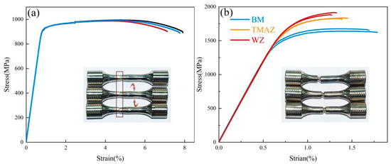
Figure 6.
Stress–strain curves: (a) dumbbell-shaped specimens; (b) specimens with a circular groove.
In the standard dumbbell tensile test, it was observed that plastic deformation occurred in the base material on both sides, whereas no plastic deformation occurred in the weld zone located in the middle of the IFW joint. Combined with the obvious differences in the microstructure of each zone of IFW joints, it was speculated that there might be considerable differences in the tensile properties of each zone. To investigate the differences in tensile properties of each zone, circular grooves were further machined in the WZ, TMAZ, and BM, so that IFW joints preferentially fractured in the corresponding zones.
Figure 6b shows the tensile stress–strain curves of the specimens with circular grooves in each zone. The inset in the figure shows that all specimens fractured at the bottom of their corresponding circular grooves. The bottom of the circular grooves generated severe stress concentrations, and the stress concentrations resulted in recorded stress values that were much higher than normal; thus, the values obtained were only of relative significance. According to the tensile stress–strain curve, it can be observed that the relative tensile strength gradually increased from the BM to WZ, whereas the relative strain value at fracture gradually decreased. The information provided by the stress–strain curve led to the preliminary conclusion that the welded joint increased in strength but decreases in plasticity from the BM to WZ.
Figure 7 shows the tensile fractures of three types of specimens with circular grooves. where Figure 7a–c are the low-magnification SEM images of the tensile fractures of the three specimens, BM:G, TMAZ:G, and WZ:G, respectively. The inset in the upper right corner presents the optical micrograph of the tensile fracture. There is no significant difference between the optical micrographs of the three zones of the tensile fracture. Low-magnification SEM revealed that the tensile fractures formed in all three zones were mixed tough-brittle fractures. However, it can clearly be observed that the dimple reduces and the tearing ridge becomes greater from the BM to WZ tensile fracture morphology, which illustrates axial tension, from BM to WZ gradually transitioning from ductile fracture to brittle fracture.
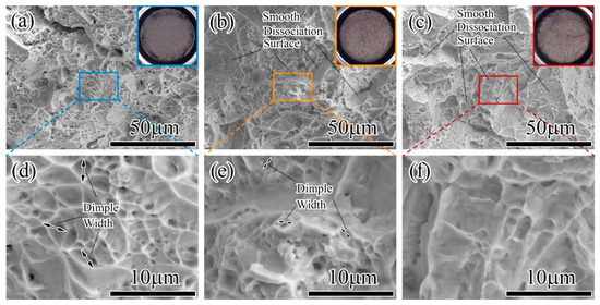
Figure 7.
Diagrams of the tensile fracture morphology for samples with grooves: (a) low-magnification BM:G; (b) low-magnification TMAZ:G; (c) low-magnification WZ:G; (d) high-magnification BM:G; (e) high-magnification TMAZ:G; (f) low-magnification WZ:G.
Figure 7d–f show high-magnification SEM images of the tensile fractures of the BM:G, TMAZ:G, and WZ:G specimens, respectively. Further increasing the magnification of SEM was mainly to observe the morphology of the dimple. The widest diameter and the deepest depth of the dimples were observed in the BM. The sizes of the dimples in the TMAZ were reduced compared with those in the BM, and some smooth dissociation surfaces appeared here. The dimples were barely observed in the WZ, and the size of the observable dimples was also the smallest; the smooth dissociation surface was also more visible compared with the TMAZ. The results of the observation of the tensile fracture morphology of the specimens with grooves also indicated the reduction in the plasticity of the welded joint from the BM to WZ. The results obtained by Ji et al. in the fracture toughness and fracture analysis of different zones of IFW joints of Ti17 titanium alloy are similar to the results of our research [21].
The increase in the tensile strength of welded joints of IFW from BM to WZ can be explained by grain refinement; this increases the grain boundaries and thus improves the strength and hardness, although grain refinement causes plasticity to occur evenly across all of the refined grains, which slightly increases the plasticity of the metal, rather than decreasing it [24,25]. The decrease in the plasticity of IFW joints from the BM to WZ can be explained by the transformation of the morphology of the microstructure. The a-phase was transformed from large-sized equiaxed crystals in BM to small-sized fine needles in the WZ, and the plasticity of equiaxed crystals was higher compared with the longitudinally and horizontally interwoven fine-needle structure. The occurrence of such microstructural transformation was also the reason for the increased number of dimples; tensile fractures also decreased from the BM to WZ, whereas the tearing ridge increased.
4. Conclusions
In this research, TA19 titanium alloy was joined by inertial friction welding, and the IFW joint with 100% combined micro-interface was obtained. The microstructure and mechanical properties of each zone of the joint were compared and analyzed. The differences in the microstructure of each zone of IFW joints were explained from the perspective of redistribution of alloying elements. The differences in mechanical properties between BM and WZ were compared in terms of overall performance (both strength and plasticity). Through the above research for TA19 titanium alloy IFW joints, we believe that perhaps the process characteristics of IFW led to the recrystallization of the WZ to produce finer, but selectively oriented grains. The grains that undergo meritocratic orientation may not have a strong tensile strength in the axial direction. The difference in mechanical properties between BM and WZ is perhaps a property unique to IFW joints, and not just to titanium. Specifically, the following conclusions were confirmed.
- (1)
- The inertia friction welding joints of the TA19 titanium alloy without cracks and with a narrow welding seam were successfully obtained. The width of the weld zone (WZ) of the joint was approximately 1.2 mm; the width of the unilateral thermo-mechanical-affected zone (TMAZ) was approximately 1.1 mm; and the width of the unilateral heat-affected zone was about 0.9 mm.
- (2)
- The BM is a duplex microstructure composed of an equiaxed primary α-phase and β-transformation structure (lamellar structure composed of base β-phase and lath α-phase. The solid solution α-phase in the HAZ transformed into a fine needle α-phase. The equiaxed primary α-phase of the TMAZ was deformed, and the β-transformation structure transformed into an α+β lamellar structure at the same time. The WZ underwent complete dynamic recrystallization during IFW and decomposed into fine α + β lamellar after post-weld heat treatment.
- (3)
- The β-stable element Mo aggregated in the BM and HAZ and played a role in stabilizing the large β-phase. In contrast, Mo elements were dispersed in TMAZ and WZ and did not play a role in stabilizing the large size β-phase, and Mo elements were fixed in place during the sharp drop in temperature after welding and no redistribution occurred.
- (4)
- The tensile test of IFW joints showed that the mean modulus of elasticity was 119.14 GPa, the mean yield strength was 972.64 MPa, the mean tensile strength was 990.56 MPa, the mean section shrinkage was 16.8%, and the location of the fracture in tension was in the BM.
- (5)
- Comparative tensile experiments were conducted for each zone of the IFW joint, and the stress–strain curves showed that from BM to WZ, the tensile strength of welded joints increased and plasticity decreased. Tensile fracture morphology shows that from BM to WZ, the tensile fracture gradually changes from ductile fracture to brittle fracture.
Author Contributions
Z.L. (Zhijun Li) and H.W. designed and supervised the experiments and test methods; Z.L. (Zihao Li) and H.W. were in charge of the IFW experiments and testing the microstructures and tensile; S.Z., Z.L. (Zhijun Li) and W.T. assisted with the sampling and data analyses. Z.L. (Zhijun Li) and Z.L. (Zihao Li) were responsible for writing and editing the manuscript. All authors have read and agreed to the published version of the manuscript.
Funding
This research was funded by the Shenzhen Science and technology R&D Fund: JCYJ20190809150001747.
Institutional Review Board Statement
Not applicable.
Informed Consent Statement
Not applicable.
Data Availability Statement
All data used to support the findings of this study are included within the article.
Conflicts of Interest
The authors declare no conflict of interest.
References
- Li, G.X.; Chandra, S.; Rashid, R.; Palanisamy, S.; Ding, S. Machinability of Additively Manufactured Titanium Alloys: A Comprehensive Review. J. Manuf. Process. 2022, 75, 72–99. [Google Scholar] [CrossRef]
- Mi, G.B.; Huang, X.; Cao, J.; Cao, C.; Huang, X. Frictional Ignition of Ti40 Fireproof Titanium Alloys for Aero-Engine in Oxygen-Containing Media. Trans. Nonferrous Met. Soc. China 2013, 23, 2270–2275. [Google Scholar] [CrossRef]
- Williams, J.C.; Boyer, R.R. Opportunities and Issues in the Application of Titanium Alloys for Aerospace Components. Metals 2020, 10, 705. [Google Scholar] [CrossRef]
- Cui, C.X.; Hu, B.M.; Zhao, L.C.; Liu, S.J. Titanium Alloy Production Technology, Market Prospects and Industry Development. Mater. Des. 2011, 32, 1684–1691. [Google Scholar] [CrossRef]
- Wang, F.; Lei, L.; Fu, X.; Song, Z.; Shi, L.; Zhang, B.; Zhang, G. Effect of Heat Treatment on Microstructures and Tensile Properties of Ta19 Alloy Fabricated by Laser Metal Deposition. Mater. Sci. Eng. A-Struct. Mater. Prop. Microstruct. Process. 2020, 782, 139284. [Google Scholar] [CrossRef]
- Li, D.R.; Wang, K.; Yan, Z.B.; Cao, Y.; Misra, R.D.K.; Xin, R.L.; Liu, Q. Evolution of Microstructure and Tensile Properties During the Three-Stage Heat Treatment of Ta19 Titanium Alloy. Mater. Sci. Eng. A-Struct. Mater. Prop. Microstruct. Process. 2018, 716, 157–164. [Google Scholar] [CrossRef]
- Berthaud, M.; Popa, I.; Chassagnon, R.; Heintz, O.; Lavkova, J.; Chevalier, S. Study of Titanium Alloy Ti6242s Oxidation Behaviour in Air at 560 Degrees C: Effect of Oxygen Dissolution on Lattice Parameters. Corros. Sci. 2020, 164, 108049. [Google Scholar] [CrossRef]
- Han, M.L.; Xu, P.W.; Wan, M.P.; Liang, Y.L.; Du, J.P.; Liang, Y. Semi-Equiaxed Structure and Tensile Properties of Ta19 Titanium Alloy. Rare Met. Mater. Eng. 2018, 47, 3768–3775. [Google Scholar]
- Zhang, M.D.; Cao, J.X.; Huang, X. Local Softening Behavior Accompanied by Dislocation Multiplication Accelerates the Failure of Ti-6al-2sn-4zr-2mo-0.1si Alloy under Dwell Fatigue Load. Scr. Mater. 2020, 186, 33–38. [Google Scholar] [CrossRef]
- Muhrat, A.; Puga, H.; Barbosa, J. Low-Temperature Brazing of Titanium Using Al-Based Filler Alloys. Adv. Mater. Sci. Eng. 2018, 2018, 4570120. [Google Scholar] [CrossRef]
- Auwal, S.T.; Ramesh, S.; Yusof, F.; Manladan, S.M. A Review on Laser Beam Welding of Titanium Alloys. Int. J. Adv. Manuf. Technol. 2018, 97, 1071–1098. [Google Scholar] [CrossRef]
- Mironov, S.; Sato, Y.S.; Kokawa, H. Friction-Stir Welding and Processing of Ti-6al-4v Titanium Alloy: A Review. J. Mater. Sci. Technol. 2018, 34, 58–72. [Google Scholar] [CrossRef]
- Liu, Y.; Zhao, H.Y.; Peng, Y.; Ma, X.F. Microstructure and Tensile Strength of Aluminum/Stainless Steel Joint Welded by Inertia Friction and Continuous Drive Friction. Weld. World 2020, 64, 1799–1809. [Google Scholar] [CrossRef]
- Yang, J.; Li, J.L.; Jin, F. Effect of Welding Parameters on High-Temperature Tensile and Fatigue Properties of Fgh96 Inertia Friction Welded Joints. Weld. World 2019, 63, 1033–1053. [Google Scholar] [CrossRef]
- Wen, H.Y.; You, G.Q.; Ding, Y.H.; Li, P.Q.; Tong, X.; Guo, W. Effect of Friction Pressure on Zk60/Ti Joints Formed by Inertia Friction Welding. J. Mater. Eng. Perform. 2019, 28, 7702–7709. [Google Scholar] [CrossRef]
- Turner, R.P.; Howe, D.; Thota, B.; Ward, R.M.; Basoalto, H.C.; Brooks, J.W. Calculating the Energy Required to Undergo the Conditioning Phase of a Titanium Alloy Inertia Friction Weld. J. Manuf. Process. 2016, 24, 186–194. [Google Scholar] [CrossRef]
- Jeong, H.S.; Cho, J.R.; Oh, J.S.; Kim, E.N.; Choi, S.G.; Ha, M.Y. Inertia Friction Welding Process Analysis and Mechanical Properties Evaluation of Large Rotor Shaft in Marine Turbo Charger. Int. J. Precis. Eng. Manuf. 2010, 11, 83–88. [Google Scholar] [CrossRef]
- Zhao, Z.L.; Song, X.; Cao, L.; Xu, W.; Yao, Z.; Guo, H. Effect of Isothermal Deforming on the Microstructure and Property of Inertial Friction Welding Imi834/Ti6246 Dual Titanium Alloy. Rare Met. Mater. Eng. 2020, 49, 2388–2392. [Google Scholar]
- Li, Z.H.; Zhao, S.; Li, Z.; Wang, M.; Wu, F.; Wang, H.; Zhou, J. Investigation of the Mechanical Properties of Inertia-Friction-Welded Joints of Tc21 Titanium Alloy. Processes 2022, 10, 752. [Google Scholar] [CrossRef]
- Wu, Y.Q.; Zhang, C.; Zhou, J.; Liang, W.; Li, Y. Analysis of the Microstructure and Mechanical Properties During Inertia Friction Welding of the near-Alpha Ta19 Titanium Alloy. Chin. J. Mech. Eng. 2020, 33, 88. [Google Scholar] [CrossRef]
- Ji, Y.P.; Wu, S.J. Fracture Toughness Assessment at Different Regions in an Inertial Friction Welded Ti-5al-2sn-2zr-4mo-4cr Alloy Plate. Int. J. Mater. Res. 2021, 112, 215–222. [Google Scholar] [CrossRef]
- Foul, A.; Aranas, C.; Guo, B.; Jonas, J. Dynamic Transformation of A → Β Titanium at Temperatures Below the Β-Transus in Commercially Pure Titanium. Mater. Sci. Eng. A 2018, 722, 156–159. [Google Scholar] [CrossRef]
- Wang, H.Y.; Li, Z.; Zhao, S.; Li, Z.; Tang, W.; Wu, F.; Zhou, J. Microstructure Evolution of Inertia Friction Welded Joints of Tc21 Titanium Alloy. Processes 2022, 10, 1086. [Google Scholar] [CrossRef]
- Du, B.N.; Yang, J.; Cui, C.; Sun, X. Effects of Grain Refinement on the Microstructure and Tensile Behavior of K417g Superalloy. Mater. Sci. Eng. A-Struct. Mater. Prop. Microstruct. Process. 2015, 623, 59–67. [Google Scholar] [CrossRef]
- Wang, C.F.; Wang, M.; Shi, J.; Hui, W.; Dong, H. Effect of Microstructure Refinement on the Strength and Toughness of Low Alloy Martensitic Steel. J. Mater. Sci. Technol. 2007, 23, 659–664. [Google Scholar]
Disclaimer/Publisher’s Note: The statements, opinions and data contained in all publications are solely those of the individual author(s) and contributor(s) and not of MDPI and/or the editor(s). MDPI and/or the editor(s) disclaim responsibility for any injury to people or property resulting from any ideas, methods, instructions or products referred to in the content. |
© 2023 by the authors. Licensee MDPI, Basel, Switzerland. This article is an open access article distributed under the terms and conditions of the Creative Commons Attribution (CC BY) license (https://creativecommons.org/licenses/by/4.0/).