
Modeling and Analysis of New Power Devices Based on Linear Phase-Shifting Transformer


Abstract
:1. Introduction
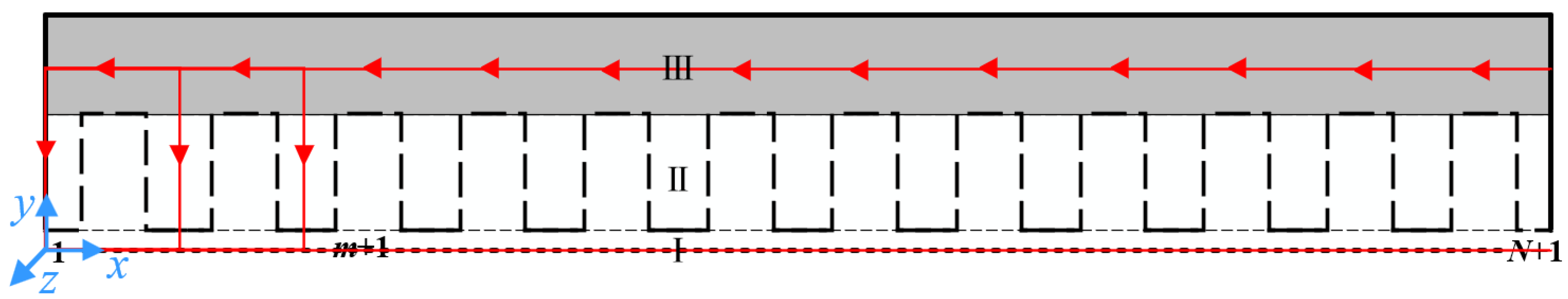
2. Analytical Model of Slotless Magnetic Field
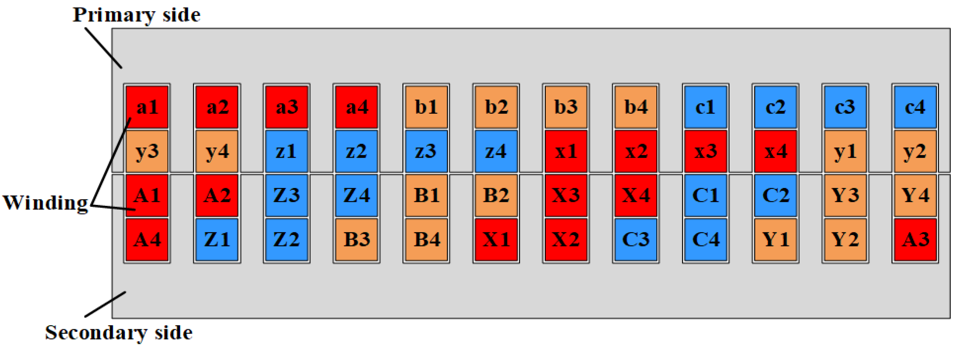
- 1.
- The primary and secondary side end flux leakage is ignored.
- 2.
- The flux lines in the virtual teeth are all arranged in the longitudinal direction, and the flux lines in the yokes are all arranged in the normal direction.
- 3.
- The size of the primary- and secondary-side virtual teeth is the same.
- 4.
- The interaction of adjacent slots (virtual slots) is ignored.
3. Air-Gap Relative Permeance Based on SCT
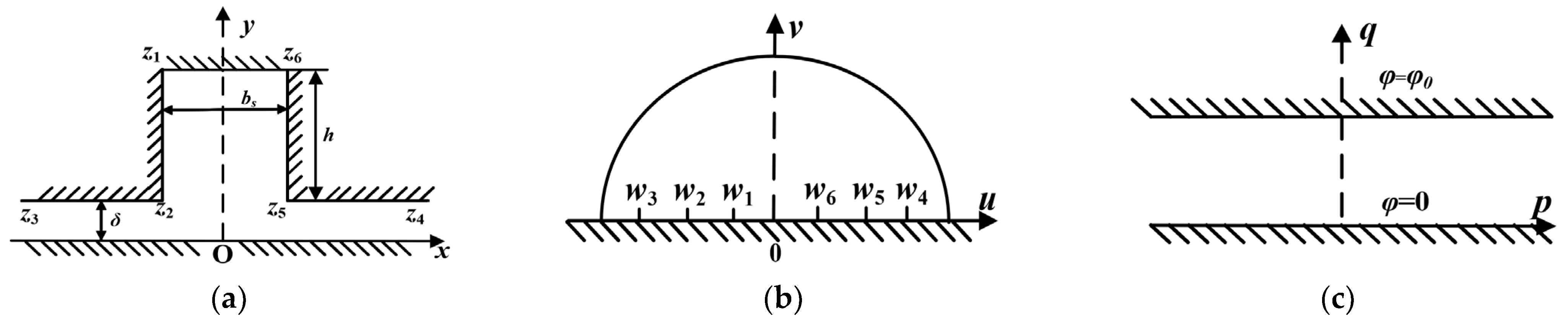
3.1. Cogging Effect
- 1.
- The primary side is slotted, and the secondary side is a smooth plane.
- 2.
- The magnetic conductivity of the core on the primary and secondary sides is infinite.
- 3.
- Both the primary and secondary sides of the iron core are planes with equal magnetic potential, one of which is 0 and the other φ0.
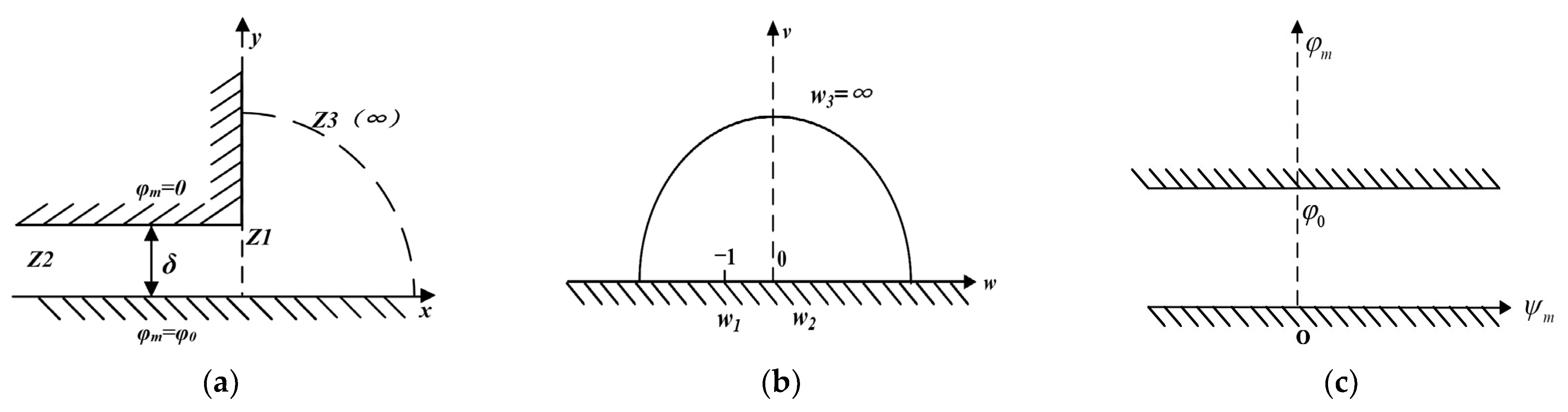
3.2. End Effect
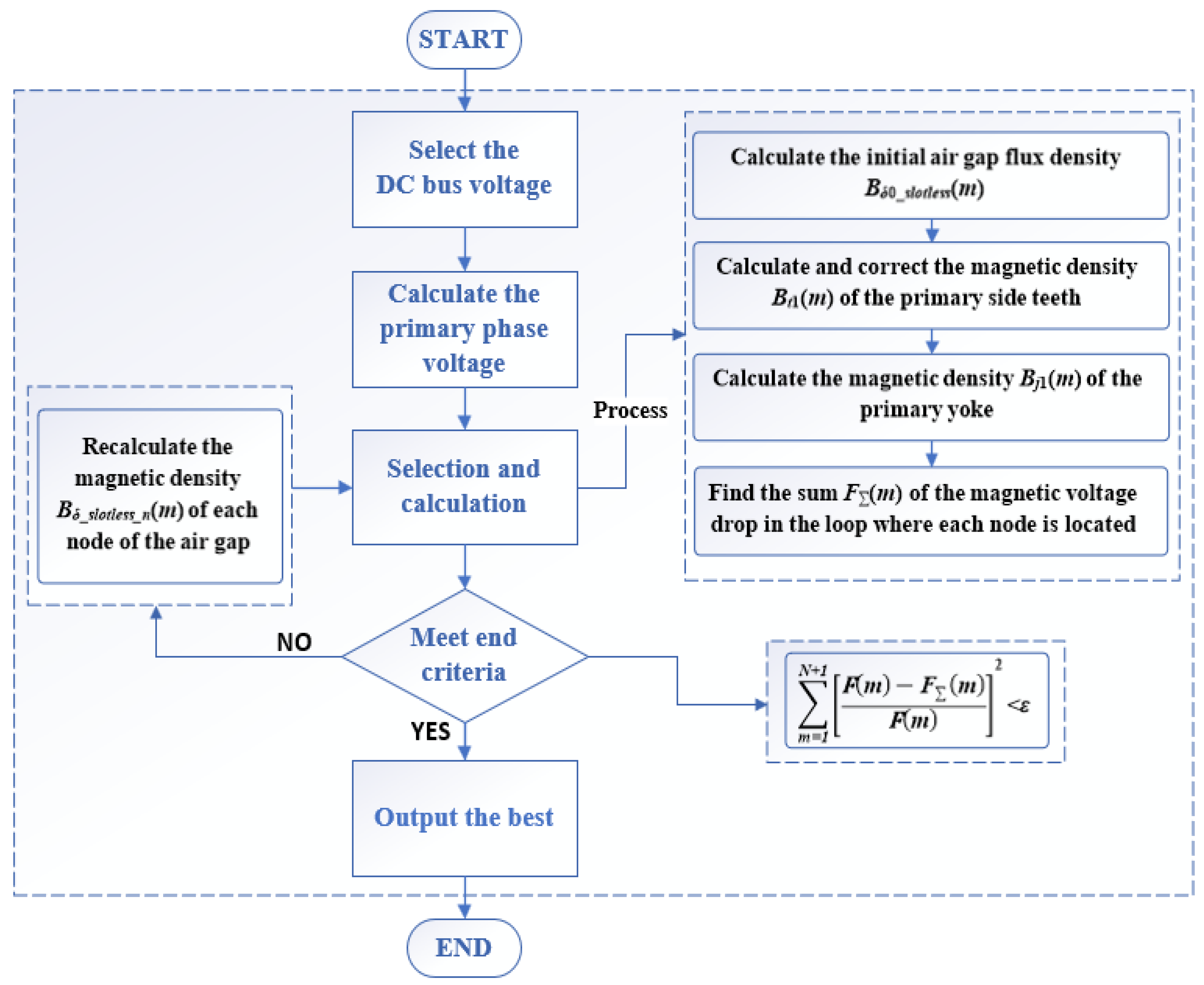
4. Results
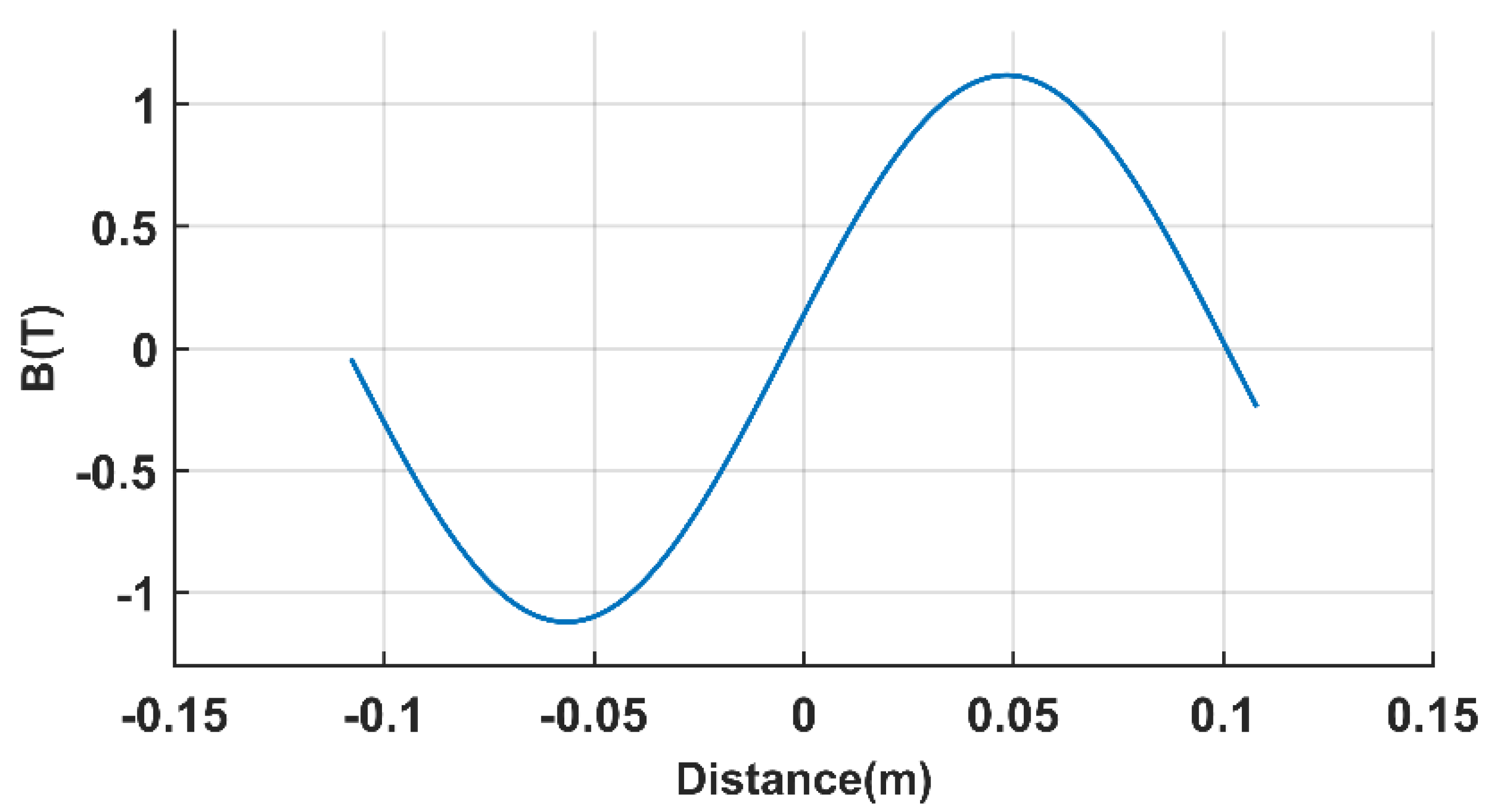
4.1. Analytical Results
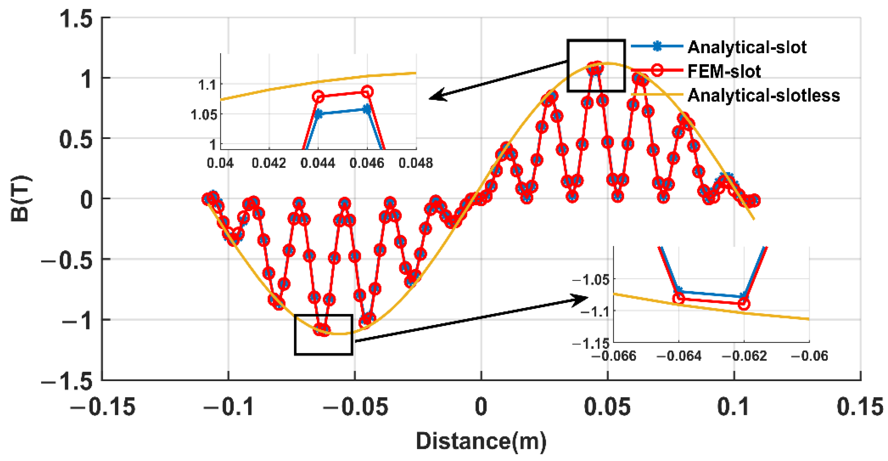
4.2. FEM Verification
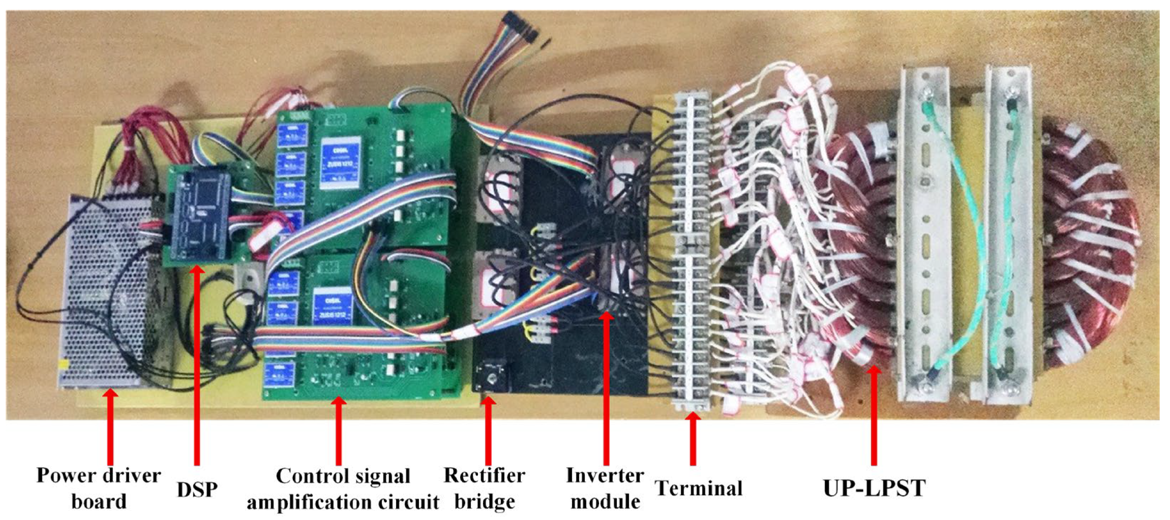
4.3. Test Verification
5. Conclusions
Author Contributions
Funding
Institutional Review Board Statement
Informed Consent Statement
Data Availability Statement
Conflicts of Interest
References
- Mastny, P.; Moravek, J.; Drapela, J.; Vrana, M.; Vojtek, M. Problems of Verification of Operating Parameters of DC/AC Inverters and Their Integration into the Distribution System in the Czech Republic. In Proceedings of the CIRED Porto Workshop 2022: E-Mobility and Power Distribution Systems, Porto, Portugal, 2–3 June 2022; pp. 304–308. [Google Scholar] [CrossRef]
- Iqbal, S.; Hossain, A.; Islam, J.; Surja, A.S.; Kabir, M. Enhancing Voltage Stability of Inter-Area Multi-Machine Power Systems using Reinforcement Learning-based STATCOM. In Proceedings of the 2022 International Conference on Advancement in Electrical and Electronic Engineering (ICAEEE), Gazipur, Bangladesh, 24–26 February 2022; pp. 1–4. [Google Scholar] [CrossRef]
- Jalilian, A.; Muttaqi, K.M.; Sutanto, D.; Robinson, D. Distance Protection of Transmission Lines in Presence of Inverter-Based Resources: A New Earth Fault Detection Scheme During Asymmetrical Power Swings. IEEE Trans. Ind. Appl. 2022, 58, 1899–1909. [Google Scholar] [CrossRef]
- Calar, M.; Durna, E.; Kayisli, K. 3-Phase Multi-Pulse Rectifiers with Different Phase Shifting Transformers and Comparison of Total Harmonic Distortion. In Proceedings of the 2022 9th International Conference on Electrical and Electronics Engineering (ICEEE), Alanya, Turkey, 29–31 March 2022; pp. 60–64. [Google Scholar] [CrossRef]
- Yuan, D.; Yin, Z.; Wang, S.; Duan, N. Multi-level Transient Modeling of the Aeronautic Asymmetric 18-pulse Phase-shifting Auto-transformer Rectifier in Full-cycle Design. IEEE Trans. Transp. Electrif. 2022, 8, 3759–3770. [Google Scholar] [CrossRef]
- Luo, M.; Dujic, D.; Allmeling, J. Leakage Flux Modeling of Medium-Voltage Phase-Shift Transformers for System-Level Simulations. IEEE Trans. Power Electron. 2018, 34, 2635–2654. [Google Scholar] [CrossRef]
- Chen, G.; Ding, L.; Tang, F.; Teng, Y. The study of increasing Chongqing sectional transmission capacity using phase-shifting transformer. Sichuan Electr. Power Technol. 2014, 37, 49–54. (In Chinese) [Google Scholar]
- Xiong, X.; Zhao, J.H.; Ding, H.; Sun, P.; Peng, W. Research on end effect of linear phase-shifting transformer. J. Xi’an Jiaotong Univ. 2017, 51, 110–115. (In Chinese) [Google Scholar]
- Zhang, Z.M.; Zhao, J.H.; Ma, Y.Z.; Xu, H. Analytical modeling of inverter system of linear phase-shifting transformer. Chin. J. Electr. Eng. 2019, 14, 54–60. (In Chinese) [Google Scholar]
- Zhao, J.H.; Xu, H.; Guo, G.Q. Design of 12/3-phase linear phase-shifting transformer. J. Nav. Eng. Univ. 2021, 33, 1–6. (In Chinese) [Google Scholar]
- Zhao, J.H.; Ma, Y.Z.; Sun, P. Multiple superposition inverter system based on linear phase-shifting transformer. Electr. Power Autom. Equip. 2019, 39, 183–188. (In Chinese) [Google Scholar] [CrossRef]
- Sterling, H. Harmonic Field Effects in Induction Machines. IEEE Rev. 1977, 23, 841. [Google Scholar] [CrossRef]
- Wu, L.J.; Zhu, Z.Q.; Staton, D.A.; Popescu, M.; Hawkins, D. Subdomain Model for Predicting Armature Reaction Field of Surface-Mounted Permanent-Magnet Machines Accounting for Tooth-Tips. IEEE Trans. Magn. 2011, 47, 812–822. [Google Scholar] [CrossRef]
- Wu, L.J.; Zhu, Z.Q.; Staton, D.; Popescu, M.; Hawkins, D. An Improved Subdomain Model for Predicting Magnetic Field of Surface-Mounted Permanent Magnet Machines Accounting for Tooth-Tips. IEEE Trans. Magn. 2011, 47, 1693–1704. [Google Scholar] [CrossRef]
- Zhu, Z.Q.; Wu, L.J.; Xia, Z.P. An Accurate Subdomain Model for Magnetic Field Computation in Slotted Surface-Mounted Permanent-Magnet Machines. IEEE Trans. Magn. 2009, 46, 1100–1115. [Google Scholar] [CrossRef]
- Jikun, Y.; Liyi, L.; Jiangpeng, Z. Analytical calculation of air-gap relative permeance in slotted permanent magnet synchronous motor. Trans. China Electrotech. Soc. 2016, 31, 45–52. [Google Scholar]
- Fu, L.; Zuo, S.; Ma, C.; Tan, Q. Analytical calculation of armature reaction field including slotting effects in PMSM with concentrated fraction-al-slot winding. Trans. China Electrotech. Soc. 2014, 29, 29–35. [Google Scholar]
- Zhu, Z.Q.; Howe, D. Instantaneous magnetic field distribution in brushless permanent magnet DC motors, part III: Effect of stator slotting. IEEE Trans. Magn. 1993, 29, 143–151. [Google Scholar] [CrossRef]
- Lv, Y.; Cheng, S.; Wang, D.; Chen, J. A Fast Method for Calculating the Air-Gap Flux and Electromagnetic Force Distribution in Surface Permanent Magnet Motors. In Proceedings of the 2020 IEEE 9th International Power Electronics and Motion Control Conference (IPEMC2020-ECCE Asia), Nanjing, China, 29 November–2 December 2020; pp. 1973–1977. [Google Scholar] [CrossRef]
- Tang, Y. Electromagnetic Fields in Motors, 2nd ed.; Science Press: Beijing, China, 1998. [Google Scholar]
- Lee, S.-H.; Yang, I.-J.; Kim, W.-H.; Jang, I.-S. Electromagnetic Vibration-Prediction Process in Interior Permanent Magnet Synchronous Motors Using an Air Gap Relative Permeance Formula. IEEE Access 2021, 9, 29270–29278. [Google Scholar] [CrossRef]
- Chang, J. New direct drive method for large telescope base on Arc PMLSM. Univ. Chin. Acad. Sci. 2013. [Google Scholar]
- Guo, G.; Zhao, J.; Wu, M.; Xiong, Y. Analytical Calculation of Magnetic Field in Fractional-Slot Windings Linear Phase-Shifting Transformer Based on Exact Subdomain Model. IEEE Access 2021, 9, 122351–122361. [Google Scholar] [CrossRef]
- Jiang, H.; Su, Z.; Wang, D. Analytical Calculation of Active Magnetic Bearing Based on Distributed Magnetic Circuit Method. IEEE Trans. Energy Convers. 2020, 36, 1841–1851. [Google Scholar] [CrossRef]
- Wang, N.; Wu, X.; Chen, J.; Guo, Y.; Cheng, S. A Distributed Magnetic Circuit Approach to Analysis of Multiphase Induction Machines with Nonsinusoidal Supply. IEEE Trans. Energy Convers. 2014, 30, 522–532. [Google Scholar] [CrossRef]
- Guo, Y.; Wang, D.; Liu, D.; Wu, X.; Chen, J. Magnetic Circuit Calculation of Non-Salient Pole Synchronous Generator Based on Distributed Magnetic Circuit Method. In Proceedings of the 2011 International Conference on Electrical Machines and Systems, Beijing, China, 20–23 August 2011; pp. 1–6. [Google Scholar] [CrossRef]
- Huang, C.; Sun, Z.; Xu, J.; Zeng, R.; Zhang, Y.; Han, Z.; Li, M. Calculation Method of Nonlinear Magnetic Circuit and Motor Performance Analysis for High-Power Linear Induction Motor. In Proceedings of the 2021 13th International Symposium on Linear Drives for Industry Applications (LDIA), Wuhan, China, 1–3 July 2021; pp. 1–6. [Google Scholar] [CrossRef]
- Guo, G.; Zhao, J.; Xiong, Y.; Wu, M. Analytical Calculation of Open-Circuit Magnetic Field in Linear Phase-Shifting Transformer Based on Exact Subdomain Model. IEEJ Trans. Electr. Electron. Eng. 2021, 17, 72–81. [Google Scholar] [CrossRef]


| z Plane | θ * | w Plane | ||
|---|---|---|---|---|
| Point | Coordinate | Point | Coordinate | |
| z1 | −bs/2 + j(h + δ) | π/2 | w1 | −1 |
| z2 | −bs/2 + jδ | 3π/2 | w2 | −a |
| z3 | −∞ + j0 | 0 | w3 | −b |
| −∞ + jδ | ||||
| z4 | +∞ + j0 | 0 | w4 | b |
| +∞ + jδ | ||||
| z5 | bs/2 + jδ | 3π/2 | w5 | a |
| z6 | bs/2 + j(h + δ) | π/2 | w1 | 1 |
| z Plane | θ * | w Plane | ||
|---|---|---|---|---|
| Point | Coordinate | Point | Coordinate | |
| z1 | jδ | 3π/2 | w1 | −1 |
| z2 | −∞ + j0 | 0 | w2 | 0 |
| −∞ + jδ | ||||
| z3 | +∞ | 0 | w3 | ±∞ |
| +jδ | ||||
| Symbol | Value | Meaning |
|---|---|---|
| h | 24 mm | Depth of the slot |
| bs | 12 mm | Width of the slot |
| t1 | 18 mm | Tooth pitch |
| δ | 0.3 mm | Air-gap length |
| L | 216 mm | Longitudinal length of core |
| D | 100 mm | Normal width of core |
| τ | 105 mm | Pole pitch |
| Method | Core Saturation | End Effect | Calculation Dimension | Error |
|---|---|---|---|---|
| FEM | √ | √ | 109,506 | - |
| ESM | × | × | 1136 | <5% |
| DMCM–SCT | √ | √ | 1300 | <2% |
Publisher’s Note: MDPI stays neutral with regard to jurisdictional claims in published maps and institutional affiliations. |
© 2022 by the authors. Licensee MDPI, Basel, Switzerland. This article is an open access article distributed under the terms and conditions of the Creative Commons Attribution (CC BY) license (https://creativecommons.org/licenses/by/4.0/).
Share and Cite
Xue, J.; Zhao, J.; Yan, S.; Wang, H.; Zhou, C.; Yan, D.; Chen, H. Modeling and Analysis of New Power Devices Based on Linear Phase-Shifting Transformer. Processes 2022, 10, 1596. https://doi.org/10.3390/pr10081596
Xue J, Zhao J, Yan S, Wang H, Zhou C, Yan D, Chen H. Modeling and Analysis of New Power Devices Based on Linear Phase-Shifting Transformer. Processes. 2022; 10(8):1596. https://doi.org/10.3390/pr10081596
Chicago/Turabian StyleXue, Jie, Jinghong Zhao, Sinian Yan, Hanming Wang, Changduo Zhou, Dongao Yan, and Hansi Chen. 2022. "Modeling and Analysis of New Power Devices Based on Linear Phase-Shifting Transformer" Processes 10, no. 8: 1596. https://doi.org/10.3390/pr10081596
APA StyleXue, J., Zhao, J., Yan, S., Wang, H., Zhou, C., Yan, D., & Chen, H. (2022). Modeling and Analysis of New Power Devices Based on Linear Phase-Shifting Transformer. Processes, 10(8), 1596. https://doi.org/10.3390/pr10081596