Abstract
The novel modified absorption heat pump (MAHP) with the H2O-LiBr working mixture for cogeneration applications is introduced. The MAHP can simultaneously produce electric energy and heat revaluation. The proposed system has the particularity that it can be powered by alternative thermal sources (such as solar energy, biomass, geothermal) or industrial waste heat, thus promoting the production and efficient use of clean energy. The effects of pressure ratio (RP), source or supply temperature (TGH), and the energy revaluation gradient (GTL) are analyzed. The critical parameters of the proposed system are evaluated, including thermal efficiency (), exergetic efficiency (), revaluated heat (), as well as net power produced (). For the MAHP analysis, RP and TGH operating ranges were chosen at 1.1–15.0 and 100–160 °C, respectively. The results show that of 87% can be obtained, having the maximum performance in TGH of 120 °C, RP of 1.1, and GTL of 35 °C. The varies between 51% and 55%, having a maximum GTL of 45 °C. On the other hand, achieves values between 260 and 582 kW, depending on the defined operating conditions.
1. Introduction
Industrial development worldwide has generated a growing energy demand, bringing an energy crisis and damage to the environment, having fossil fuels as the principal sources [1]. It is estimated that world energy consumption will continue increasing in the coming decades due to the forecast projected economic growth. In 2018, the economic growth rate was 3.7%, exceeding the 3.5% average annual growth since 2010. However, this also reflected a 2.3% increase in global energy consumption, nearly twice the average growth rate since 2010, driven by more significant heating and cooling needs in some parts of the world [2]. In this context, electricity plays a vital role in human life due to the gradual demand for energy, the accelerated increase in population, and new lifestyle trends [3].
Regarding the 2015 Paris Agreement, the urgency of the climate change challenge is highlighted [4], trying to keep the global temperature increase below 2 °C by reducing CO2 production [5]. Therefore, several countries worldwide have adopted ambitious targets to reduce their carbon footprint [4]. An alternative is using a sustainable energy system, which implies achieving adequate energy efficiency and the potential use of renewable energies; both can achieve industrial development while maintaining care for the environment and social welfare [6]. In this background, more than 50% of the energy used worldwide is wasted as heat [7]. Currently, technological developments are based on promoting sustainable energy systems and where various thermal supply sources are used. Renewable energies and industrial waste heat have enormous potential for action to address the problems caused by climate change.
Solar thermal energy can significantly boost renewable energy development. In turn, it can largely offset the adverse effects of climate change and improve the world’s energy supply. For example, solar thermal energy is used in industrial, commercial, and residential applications through different technologies, including steam, heating, cooling, and even electricity generation. Temperatures can be produced from 45 °C to over 300 °C, making it potentially helpful energy for many sectors. By 2021, the annual solar thermal energy yield amounted to 425 TWh, which correlates to savings of 45.7 million tons of oil and 147.5 million tons of CO2 avoided [8].
Fan et al. [9] presented a bibliographic review of the state of the art of solar sorption systems (absorption and adsorption). The analysis shows that solar-powered sorption technologies are attractive alternatives to demand energy conservation and environmental protection. Ayou et al. [10] and López-Villada et al. [11] presented various systems for simultaneous electrical energy and cooling production. They obtained high first and second law efficiencies due to the greater internal use of the thermal resource, guaranteeing that the absorption systems have a broad spectrum of applications. Arabkoohsar et al. [12,13] analyze the effect of employing parabolic through solar collectors-Powered absorption chiller for co-supply in heating and cooling systems. The results demonstrate that the system feeds district heating with a heat supply rate of over 1 MW for about three months, and the internal rate of return of the system is 5.7% for 8 years of operation. Rahman et al. [14] implemented a simulation model of a solar absorption cooling system for air conditioning in Pakistan. The evacuated glass tube collectors use R-410A as heat transfer fluid. The system has successfully provided the desired room temperature of 26 °C with total reliance on solar thermal energy. Düzcan et al. [15] analyze the usage potential of the evacuated tube collectors (ETCs) and the flat plate collectors (FPCs) for assisting an absorption chiller with the H2O-LiBr pair. Through the tests carried out, the evacuated tube collector obtained the best results. Ali et al. [16] show the design and performance of an absorption system using a non-tracking semi-circular trough (SCT) solar collector. The experimental results show that a chilled water output temperature of around 10–15 °C, with a record 3.3 °C, was achieved when the chiller reached an operating temperature of 120 °C. Behzadi et al. [17] propose a novel hybrid renewable-based cold production system consisting of evacuated solar collectors integrated with a biomass heater, thermal storage tanks, and an absorption machine. The system’s performance is simulated and assessed for a study case hospital in India. Nami et al. [18] propose a modeling and analysis of biomass- and solar-driven combined cooling, heating, and power system. Results showed that the designed system could feed 1241 kW of space heating, 101.5 kW of domestic hot water, and 55.35 kW of chilled water as space cooling, besides delivering 1 MWe power. Nasir et al. [19] present an assessment of a trigeneration system powered by biomass. The system analyzed was designated to provide 250 kW of electricity, cooling values between 19 and 22 kW, and heating values ranging from 879 to 1255 kW. Furthermore, the second law efficiency of the system was found to be approximately 56%. Siddiqui et al. [20] present a new solar and geothermal-based integrated system developed for electricity, fresh water, hydrogen, and cooling. The system’s overall energy efficiency obtained was 42.3%. Chen et al. [21] analyze a system for the combined production of heat and power (CHP), taking advantage of a geothermal energy source. The results demonstrate that the increased allocation ratio of mixed water for the heat pumps raised the output and coefficient of performance (COP).
On the other hand, many industries worldwide reject this energy into the atmosphere at temperatures close to 230 °C. In addition, residual heat can produce helpful energy products, reduce CO2 emissions, and create sustainable systems and efficiency. Waste heat recovery systems are a promising group of technologies that can take energy wasted from a process and transform it into usable thermal, electrical, or mechanical energy. Today, conventional waste heat recovery technologies operate mainly with different systems based on thermodynamic cycles, which can work with cleaner/sustainable sources such as solar thermal energy [22]. For the latter, the most suitable are the organic Rankine cycle (ORC), the Kalina cycle (KC), the Goswami cycle (GC), absorption heat pump (AHP), and cogeneration cycles to obtain energy, calefaction, and refrigeration [23]. KC is another thermodynamic cycle for low and medium-temperature heat recovery. Unlike a pure organic fluid, such as the one used in the ORC, it has the main characteristic of a non-constant temperature during vaporization and condensation. Compared to its competitors, it translated into better performance under the same operating conditions [24]. The GC combines the power cycle with the absorption refrigeration cycle and thus provides various operating conditions where the system offers both power and sensible cooling [25].
Regarding the implementation of sorption systems in cogeneration applications, a detailed bibliographic review carried out by Kumar et al. [26] establishes that one of the main advantages of using these systems is the low temperatures that are needed for their operation, which can range between 50 and 95 °C, with applications in refrigeration, desalination, and air conditioning. Köse et al. [27] conducted a theoretical comparison through simulations between the KC and ORC, considered the most critical low-temperature energy conversion systems in industrial waste heat utilization. The most attractive design for using residual heat was ORC, obtaining a thermal efficiency of 25.95%, operating with the working fluid n-pentane. Nevertheless, KC was more economically viable, with an estimated payback period of 3.93 years. Akimoto et al. [28] propose an analysis of the combined performance of power generation and economic evaluation for integrating a system composed of AHP coupled to KC, operating with a low-temperature heat source of approximately 100 °C. The conclusions showed that the system comprising KC + AHP + KC generally delivers the best results, with a power generation between 10 and 25 kW, a thermal efficiency of 1.2–2.9%, and an exergetic efficiency of around 10%. Aksar et al. [29] designed, analyzed, and compared the KC, the Rankine cycle, and the simple cycle of pure ammonia with residual gases at 350 °C. The results showed that the KC with cogeneration reported a maximum thermal and exergetic efficiency of 72.13% and 78.60%, respectively. Marshall et al. [30] performed a techno-economic evaluation of multi-cycle organic Rankine-assisted heat pumps (AHP-ORC). The maximum values of COP and efficiency were obtained with R161/n-pentane, with values of 13.2% and 4.1%, respectively. Liu et al. [31] proposed the theoretical evaluation of a system composed of KC coupled to an H2O-LiBr absorption refrigeration system. The power generation was improved by 45% compared to the conventional KC, and the COP increased from 0.1158 to 0.1678. Cao et al. [32] used a thermodynamic analysis establishing a mathematical model for a simultaneous cooling and power generation cycle based on an absorption refrigeration cycle coupled to KC, driven by a low-temperature heat source between 100 and 135 °C. The results obtained were that the exergetic efficiency increases with the expander inlet temperature, as well as with the concentration of the basic NH3-H2O solution. Wang et al. [33] suggested a new combined refrigeration and energy production at a maximum temperature of 200 °C. The output power of the turbine, the cooling power, and the thermal and exergetic efficiency of the system had their maximum values of 37.63 kW, 75.12 kW, 13.72%, and 5.40%, respectively. Padilla et al. [34] present a parametric analysis of the GC using the binary mixture NH3-H2O. The heat source temperature was selected between 90 and 170 °C, finding the maximum theoretical energy and exergy efficiencies of 21% and 92%, respectively. To improve the performance of the Goswami cycle, multiple researchers such as Zare et al. [35], Xu et al. [36], and Demirkaya et al. [37] proposed the use of internal rectification, which consists of dividing the flow at the outlet of the pump in such a way that one current goes to the economizer. In contrast, the other goes directly to the rectifier.
As seen in the theoretical framework, alternative energy sources have a vast application, coupled with a wide variety of systems that can take advantage of these resources. For example, solar thermal energy and biomass can meet urban and rural needs. The waste heat recovery systems are mainly used to meet industrial needs, and geothermal energy can offer a wide range of possible applications in geographical areas where the resource is available [38].
Based on the bibliographic review, a novel modified absorption heat pump (MAHP) study is presented for cogeneration applications. The system can simultaneously produce electrical energy and revalued heat. The proposed method has the peculiarity that it can be powered by alternative thermal sources (such as solar energy, biomass, or geothermal energy) or industrial waste heat. In both cases, it is intended to produce clean energy to promote the use of sustainable processes that are friendlier to the environment. For this reason, it is essential to analyze the operating conditions, the amounts of energy, and the energy performance achieved with the MAHP.
2. Description of the MAHP
The MAHP cycle is composed of the union of a type I heat pump, a type II heat pump, and a turbine to take advantage of the pressure gradient in the system [39,40] (see Figure 1). In the case of MAHP, the maximum pressure and temperature of the system are used to provide mechanical energy for generating electricity. The expansion in the turbine is carried out using the maximum and minimum pressure of the system, PH and PL, respectively, to ensure higher power output. In addition, the revalued thermal energy or from the absorption process can be used in secondary subsystems [39], offering greater versatility in operations and a higher performance system.
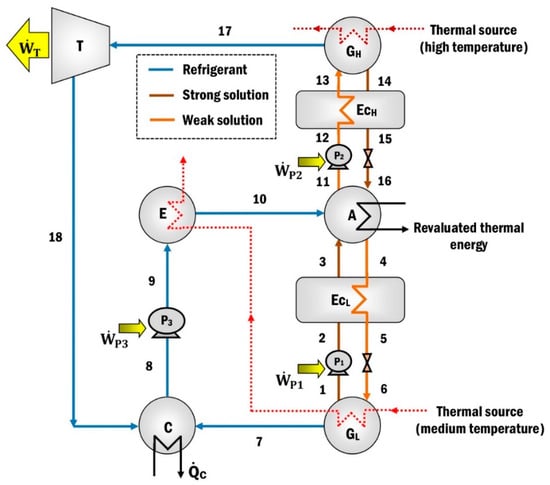
Figure 1.
The modified absorption heat pump (MAHP).
The system operates on three pressure and four temperature levels (two temperatures from a thermal source, a revalued energy temperature, and a thermal sink). The external source () exchanges heat in the high-pressure generator (GH) to produce refrigerant at a high temperature and pressure (state 17). The water vapor is expanded in the turbine (T), producing mechanical energy (). The refrigerant leaves the turbine at low pressure and temperature (state 18) and goes toward the condenser (C), where the water vapor is condensed, extracting a quantity of heat ().
A second heat source is supplied at an intermediate temperature to the evaporator (E) and the low-pressure generator (GL). The heat provided to the GL is used to heat the dilute solution (weak solution state 6) that arrives from the absorber to have a second production of the refrigerant vapor (state 7). The concentrated solution (strong solution) leaving the GL is pumped (state 2) and preheated (state 3) in the heat exchanger (EcL) before entering the absorber (A). The steam produced in the GL (state 7) passes to the condenser, which joins with the current that leaves the turbine (state 18) and condenses. The liquid refrigerant that exits the condenser (state 8) is pumped to the evaporator (state 9), where it receives heat from the second heat source () to evaporate the refrigerant again. Subsequently, the vapor refrigerant is sent to the absorber (state 10), where it is absorbed by the concentrated solution that comes from the GL (state 3) and GH (state 16). As a result of the absorption process, the available heat () is released, which is considered revalued because it is at higher energy levels than the thermal loads supplied in the GL and E. The weak solution, a product of the refrigerant absorption process, is divided into two streams (states 4 and 11). Finally, flow 4 is sent to the GL and flow 11 to the GH to restart the thermodynamic cycle of refrigerant production.
As mentioned above, the MAHP needs four energy levels to function correctly. First, the high-temperature thermal source (between 100 and 160 °C [39,40]) has the enormous potential of using various power sources, such as solar energy with evacuated tube collectors or concentration systems [13,14,15,16], biomass [17,18,19], geothermal energy [20,21], or industrial waste heat [1,3,4]. The medium-temperature thermal source (60–100 °C [39,40]) has excellent versatility in using different energy sources due to its low and easily attainable temperature range [12]. Therefore, in both cases, it is preponderant to promote renewable energies.
3. H2O-LiBr Work Solution Mixture
Absorption is a mass transfer process in which a substance can capture and hold another substance within itself at low pressures and temperatures. In absorption cooling, the property of a liquid substance (absorbent) is used to absorb into itself a gas vapor (refrigerant) and thus form a solution (binary mixture) [41]. The gas vapor previously absorbed can be separated by supplying thermal energy to the solution by increasing its temperature and pressure [42]. Absorption systems and conventional ones use the latent heat from the liquid-vapor phase change of the refrigerant to remove or transfer heat to the environment. However, absorption systems use two working fluids: the refrigerant responsible for removing and releasing heat and the absorbent that helps the movement of the refrigerant within the cycle [43]. There are many binary mixtures for absorption cycles. However, two of the most common mixtures are NH3-H2O (where NH3 is the refrigerant and H2O is the absorbent) and H2O-LiBr (where H2O is the refrigerant and LiBr is the absorbent) [44]. In the latter, the concentration of the LiBr solution is a ratio between the constituent’s mass and the mixture´s mass [44]. H2O-LiBr is the only binary mixture in which water is the refrigerant. The formation of solids due to their melting point at 0 °C limits their application in conventional compression systems. LiBr is a chemical compound of lithium and bromine that is hygroscopic, has the appearance of a white crystalline powder, and its solubility in water is 177 g/100 mL. In absorption refrigeration systems, there are two concentrations of LiBr, the concentrated (strong solution) that comes out of the generator and the diluted (weak solution) that comes out of the absorber. Strong concentrations of the solution range from 50% to 70% for normal operating conditions, as can be seen in Figure 2.
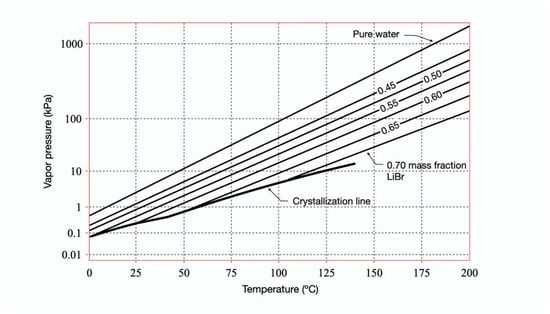
Figure 2.
Pressure-temperature diagram for water-lithium bromide [45].
As shown in Figure 2, the most significant limitation of the H2O-LiBr working solution is the crystallization zone, an area where the absorption system will not operate. The formation of solids begins when the solubility limit is exceeded, which would cause a pipe to be blocked entirely or decrease the heat exchange power.
4. MAHP Performance Parameters
This section presents the performance parameters used to carry out the thermodynamic analysis of MAHP operating with the H2O-LiBr working mixture.
4.1. Thermal Efficiency ()
Thermal efficiency can be expressed as the ratio of helpful energy produced to the energy supplied from the process. The thermal efficiency parameter can be applied to an absorption machine and is calculated based on the primary or secondary fluids. For the present study, the primary fluids or “internal flows” are considered, which are those used internally by the absorption machine (in this case, the solution H2O-LiBr) [40].
where is the revalued heat (useful heat) by the MAHP, the represents the net power produced (power produced by the turbine minus the power consumed by the pumps). Both terms describe the helpful energy obtained by the MAHP. On the other hand, represent the thermal energy supplied to the MAHP to get the desired products. In this case, the thermal loads supplied in the generators and evaporator (, and ).
4.2. Exergetic Efficiency ()
Exergy refers to the maximum work achievable from a particular form of energy transformed from one thermodynamic state in equilibrium to another. Hence, it is possible to infer the true potential of different types of energies. However, due to thermodynamic irreversibility, the exergetic efficiency indicates the degradation of the quality of different energies [46].
Using the thermodynamic states of Figure 1, Equation (2) can be expressed as:
The ambient temperature (T0) is equivalent to the sink temperature used for condensing the refrigerant (state 8). In this way, the four thermal levels of the MAHP are contemplated.
4.3. Gross Temperature Lift (GTL)
This parameter illustrates the increase or gains in temperature depending on the supply source. It represents the revaluation of energy obtained through the absorption of refrigerant in the solution, starting from the established operating conditions. GTL is defined as the temperature difference between the absorption temperature (revaluated thermal energy) and the evaporation temperature (thermal source at medium temperature) of MAHP [47].
Therefore, the higher the GTL, the higher the TA, which means that the MAHP can produce a better revalued thermal load (). The higher the , the MAHP is expected to perform better. In addition, there is more significant potential to use the thermal load in secondary processes.
5. Mathematical Modeling
The thermodynamic simulation of the MAHP was carried out using the Engineering Equation Solver (EES) software [48]. Different relevant assumptions were established for the simulation:
- The system is in thermodynamic equilibrium and a steady state [31,32,33,49,50];
- Thermal losses to the surroundings are not considered, just as friction losses are not [32,33,51];
- The H2O-LiBr solution at the generator/absorber outlet is saturated liquid [49];
- The coolant is water, and there is no carry-over of lithium bromide during the process;
- The processes in expansion valves are isenthalpic [32,33,49];
- The pumps and turbine’s isentropic efficiencies of 0.80 [10] and 0.85 [11] were considered, respectively;
- The thermal efficiency for the economizer is 0.7 [42].
The mass and energy balances for each component of the MAHP, supported by the thermodynamic states of Figure 1, are shown below.
High-pressure generator (GH):
Absorber (A):
Low-pressure generator (GL):
Turbine (T):
Evaporator (E):
Condenser (C):
Pump 1 (P1):
Pump 2 (P2):
Pump 3 (P3):
Net power ():
6. MAHP Operating Variables
As mentioned in Section 3, solution concentration performs a fundamental role in the design and operation of heat pumps. Primarily due to the operating variables range (T and P) that can move concentrations into no-go zones (zones where the system cannot work due to crystallization). The MAHP consists of two solution circuits, see Figure 1 (loop 1: states 1–2–3–4–5–6, loop 2: states 11–12–13–14–15–16). These conditions determine two concentration gradients: ΔX1 = X4 − X1 (between the absorber and low-pressure generator) and ΔX2 = X11 − X14 (between the absorber and high-pressure generator). It is essential to have a concentration gradient greater than zero so that the system has the potential to produce refrigerant and can obtain the desired products ( y ). Figure 3a shows the variation of the concentration gradients and mass flows of the MAHP for a particular study case (RP = 1.3, TC = 30 °C, TGL = 60 °C, TGH = 140 °C). In Figure 3a, as the GTL increases (higher GTL equals higher energy revalued by the MAHP), the concentration gradients gradually decrease until ΔX1 and ΔX2 tend to 0 and 0.17, respectively (at a GTL of 34 °C). The system operation stops at 34 °C because the ΔX1 = 0. This condition means no longer a concentration gradient that allows the continuous production of refrigerant. For the defined conditions, ΔX2 has concentration gradients far from zero. This condition allows the solution mass flow of the upper sub-cycle (states 11 –12 –13 –14 –15 –16) to be low and stable. For example, reaches values below 5 kg/s, which guarantees low energy consumption for pumping and, therefore, a better system’s net power. For its part, when the GTL exceeds 24 °C, ΔX1 has concentration gradients close to zero. Moreover, as the GTL continues to increase, ΔX1 tends to zero. This scenario makes the mass flows of the lower sub-cycle (states 1 –2 –3 –4 –5 –6) increasingly larger, showing an exponential behavior. The mass flow reaches values of up to 844 kg/s for a GTL of 34 °C. These results show that it is essential to establish an adequate balance between obtaining revalued energy (higher GTL) and high pumping consumption without sacrificing the overall efficiency of the MAHP.
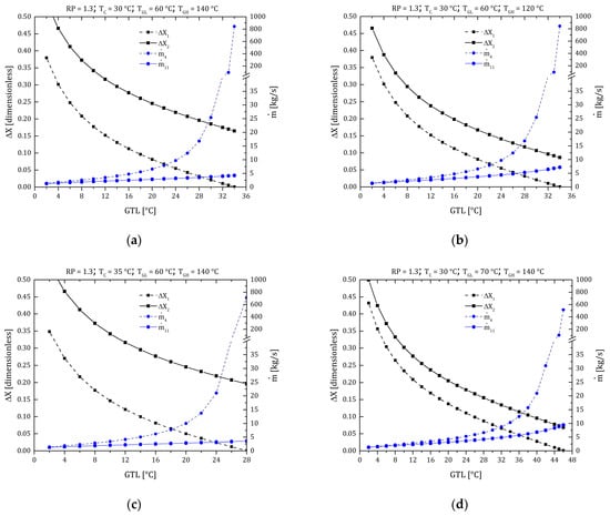
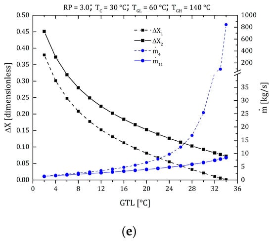
Figure 3.
Concentration gradients and mass flow ratio of the MAHP. (a) Case study: RP = 1.3, TC = 30 °C, TGL = 60 °C, TGH = 140 °C; (b) TGH effect; (c) TC effect; (d) TGL effect; (e) RPTGH effect.
Figure 3b shows the effect of the TGH variation compared to the case study. As can be seen, TGH directly affects the conditions of the upper sub-cycle (ΔX1 and remain constant). By reducing the supply power from 140 to 120 °C, the high-pressure generator has fewer resources to produce refrigerant. For this reason, ΔX2 is smaller, slightly raising up to values of 7.5 kg/s. Figure 3c shows the effect of the TC variation compared to the case study (going from a TC of 30 to 35 °C). In this case, ΔX1 starts from 0.35, a value 9% lower than in the case study. This reduction is mainly because the TC is closely linked with the PL of the system. Increasing the TC, PL also increases, modifying the ΔX1 and limiting the cycle operation. In other words, the system loses its ability to absorb the refrigerant. The higher the temperature in the refrigerant, the less efficient the absorption process is. Therefore, the energy revaluation capacity is reduced (GTL is reduced from 34 to 28 °C).
Figure 3d shows the effect of the TGL variation compared to the case study (the TGL is increased from 60 to 70 °C). In this scenario, a combined behavior is presented because a medium-temperature thermal source is supplied both in the low-pressure generator and in the evaporator. In the first part, the increase in TGH allows the system to have a greater refrigerant production capacity and to operate with better versatility since a higher GTL range can be achieved (from 34 to 46 °C of revalued thermal energy). Secondly, increasing TE also increases the system’s PM, gradually reducing ΔX2. Under these conditions, ΔX1 continues to be the limiting gradient in the operation of the MAHP, reaching mass flows of of up to 513 kg/s.
Finally, Figure 3e shows the effect of the RP variation compared to the study case (the RP is increased from 1.3 to 3.0). Although the PL and PM are defined by the phase change in the condenser and evaporator, PH is determined by the solution concentrations outside the crystallization range. As expected, changes in PH directly affect ΔX2, reducing its value and thus the operating range of the cycle (the lower sub-cycle remains intact). In addition to the above, it is expected that by increasing the system’s PH, there will be a greater capacity to produce . However, this same increase reduces the operating range. In conclusion, the thermodynamic conditions of operation of the MAHP establish concentration gradients that depend on the desired applications, the levels of the thermal sources, and the environment.
7. Thermodynamic Simulation and Results
To evaluate the results of the proposed model, different operating conditions where the MAHP can work were varied. The operating ranges are based on the choice of pressures and temperatures outside the crystallization zone of the H2O-LiBr working solution. Therefore, the RP (to define the concentrations of the solution), TGH (sources temperatures that feeds the generators), and the TA were varied (this temperature is related to the GTL or revaluated thermal gain). The ranges of operating conditions are defined in Table 1. In addition, the TGH and TGL temperature ranges are achievable with renewable energy or industrial waste heat. On the other hand, TE = TGL; this consideration is relevant to improving the absorber’s energy recovery. Therefore, it is convenient to supply the medium-temperature thermal source in the evaporator and low-pressure generator in parallel [39,40]. Finally, the condensation temperature (TC) was established as constant, which depends on the requirements of the environment where the system will be installed.

Table 1.
Operating conditions of the MAHP.
Table 2 shows a MAHP case study where the system operates at 140 °C (40 °C as energy revaluation) and with an RP of 1.1. For these conditions, the MAHP reaches the highest exergetic performance. That is, the operating conditions of the case study offer the best relationship between the products obtained concerning the sources supplied in the MAHP. As seen in Table 2, the MAHP can produce 4762 kW of and 265 kW of , getting 0.509 and 0.865 energy and exergetic performance in the system, respectively. The RP variable is vital in the operating conditions of the cycle. Although expansion work is expected to be high at high RP, it is a variable that cannot be deliberately increased, as seen below.
Table 2.
Thermodynamic simulation of the MAHP. Case study: TC = 30 °C, TGL = 70 °C, TGH = 120 °C, RP = 1.1.
7.1. MAHP Products
The main products obtained from MAHP are shown in Figure 4. In each section of Figure 4, the evolution of net power and revaluated heat is revealed concerning the effect of TGH (in decreasing order from 160 to 100 °C). The system’s net power is directly proportional to the TGH and RP, the latter variable affecting the most. This behavior is expected because, at higher TGH, a refrigerant with a higher degree of overheating is supplied at the turbine inlet. In addition, at higher RP, the net power increases due to the pressure gradient between the high and low-pressure zone of the MAHP, obtaining higher expansion power. As expected, by setting the TC and TGH (the sink temperature and the source temperature, respectively), the pressure gradients remain fixed, which causes the powers produced by the turbine to be constant throughout its range of operation. Regarding the revalued thermal load, as the MAHP obtains a higher GTL, the system shows a slight increase during the first 35 °C. However, as mentioned in Section 5, concentration gradients limit the functioning of the cycle. For this reason, above 35 °C of GTL, decreases abruptly, reducing its operating performance and reaching a maximum GTL of 45 °C. Figure 4a shows variations in net power and revalued heat between 283–582 kW and 2500–5100 kW, respectively. Furthermore, with a TGH of 160 °C, the system can operate with a maximum RP of 15. As expected, increasing RP offers better net power output. However, RP cannot be deliberately increased because it limits the operation of the thermodynamic cycle (as explained in Figure 3e). For example, with RP of 1.1, 45 °C of GTL is achieved, while with RP of 15, 7 °C is barely reached (having little operating margin). Regarding Figure 4b–d, the source temperature gradually reduces from 160 to 100 °C. As expected, having the less thermal resource, the MAHP has less capacity to produce and . The RP operating range is also reduced (to operate in areas far from solution crystallization). For a TGH of 140, 120, and 100 °C, maximum RPs of 9, 5, and 3 are reached, with net powers of 515, 441, and 375 kW, respectively.
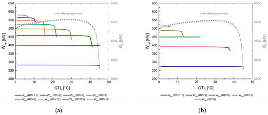
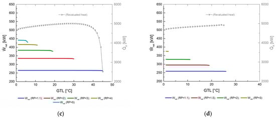
Figure 4.
Net power () and revaluated heat () as a function of GTL. (a) TGH = 160 °C; (b) TGH = 140 °C; (c) TGH = 120 °C; (d) TGH = 100 °C.
7.2. Thermal Efficiency ()
The thermal efficiency of the MAHP, as observed in Figure 5, is directly related to the pressure ratio (RP) and the changes in the temperature of the high-pressure generator (TGH). As previously observed in Figure 4, reducing the source temperature can considerably reduce the net power produced, not the revalued heat. These factors cause the thermal efficiency of the system to show slight changes. However, the most noticeable effect on the MAHP is the reduction in the RP’s operating ranges, mainly shortening the maximum achievable GTL. For example, in Figure 5a, heat is supplied at 160 °C; with the energy level of 160 °C, the MAHP reaches values of between 0.51 and 0.55 (for the first 35 °C of GTL, the thermal efficiency varies very little). In addition, the MAHP can operate in a greater range of operation between the RP of 1.1 and 3, reaching 45 °C of GTL. In addition, for RP of 5, 7, 9, 11, 13, and 15, the GTL went reduced to 34, 22, 15, 11, 7, and 4 °C, respectively. The maximum values of GTL are compared with poor thermal performances (tending to zero). A better GTL point would be around 30–35 °C without sacrificing the and without the need to operate outside the thermodynamic limit of the system. A more significant pressure gradient serves to produce greater power in the turbine. Nevertheless, the system’s thermal efficiency does not change significantly, mainly because the thermal supplies in both generators and evaporators also increase, thus compensating for the output produced concerning the required input of the MAHP. For example, in Figure 5b–d, the thermal efficiencies achieved remain almost constant. Only the RP range and GTL reduction are sacrificed with less thermal supplied. Having a greater thermal source, the MAHP operates with greater fluidity.
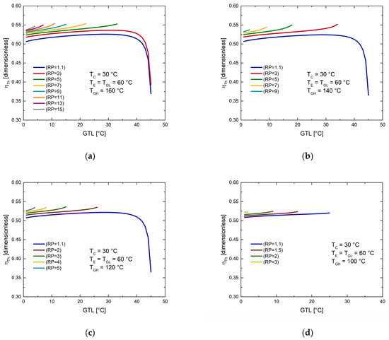
Figure 5.
Thermal efficiency () as a function of GTL at different pressure ratios (RP). (a) TGH = 160 °C; (b) TGH = 140 °C; (c) TGH = 120 °C; (d) TGH = 100 °C.
7.3. Exergetic Efficiency ()
The exergetic efficiency, as already mentioned in Section 4, is related to the amount of thermal energy that will be usable (it is a better way of equating the revalued thermal load with the power produced). Finally, in Figure 6, the exergetic efficiency of MAHP is observed as a function of GTL for different temperatures of the supply source.
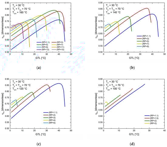
Figure 6.
Exergetic efficiency () as a function of GTL at different pressure ratios (RP). (a) TGH = 160 °C; (b) TGH = 140 °C; (c) TGH = 120 °C; (d) TGH = 100 °C.
For example, in Figure 6, unlike Figure 5, more marked behaviors are shown for what has been explained above. For a fixed source temperature and RP, increasing TA favors exergetic efficiency as continues to increase ( remains constant during operation). The thermodynamic limit operative abruptly reduces the revalued heat of the system (Figure 4), which directly affects the exergetic efficiency of the cycle (Equation (3)). For this reason, efficiencies are constantly growing as GTL increases. Subsequently, a maximum value is reached, and finally, there is an abrupt reduction in the efficiencies in the maximum values of GTL. By increasing the RP, the pressure gradient of the MAHP is improved, which benefits the production of the system. Through the exergetic efficiency, it is deduced that the RP cannot be increased without any control. For each condition, there is an appropriate relationship between and that offers the best use of the energy supplied concerning that produced. For each section of Figure 6, at the same RP (for example, RP = 1.1), the exergetic efficiencies increase as there is a minor thermal supply source (or at least for low RP). This behavior is to be expected because the exergy supplied in the high-pressure generator has a more significant influence than that achieved with the desired products. Secondly, operating at higher supply temperatures means higher environmental thermal losses. Figure 6a shows that maximum (between 32 and 40 °C of GTL) of 76%, 83%, 84%, and 80% are reached, for the RP of 1.1, 3, 5, and 7, respectively, further reducing its exergetic efficiency for higher RP (0.72 with RP of 15). Figure 6b achieves its best performances for RP between 1.1 and 3, GTL between 30 and 35 °C, and maximum of 0.86. Figure 6c achieves its best performances for RP between 1.1 and 2, GTL between 30 and 39 °C, and ultimate of 0.87. Finally, Figure 6d is considered the worst operating condition since the MAHP works with the least thermal resource. In this case, it is only possible to operate between 1.1 and 2 RP and 27 °C of GTL. However, it is essential to mention that despite the extreme conditions of the last scenario, the MAHP continues to function and produce the desired outputs, greatly favoring its application in various sustainable processes.
As seen in Section 7, the MAHP is a novel system with high efficiencies compared to the systems presented in the introduction. The proposed configuration of nested heat pumps coupled with a turbine provides enormous versatility of operation. On the one hand, MAHP can operate with various sources of supply; on the other, working conditions can be sought to produce high revalued thermal loads or better expansion power. Otherwise, these characteristics allow the MAHP to have an important field of development for applications in the industrial and renewable energy sectors.
8. Conclusions
The analysis of a modified absorption heat pump (MAHP) for cogeneration applications has been made. The MAHP works with the binary solution H2O-LiBr and simultaneously produces expansion work () and the revaluation of a thermal source (. The working mixture presents enormous potential for development in these new cogeneration systems. However, operating the cycle in regions far from the crystallization zones is essential. In this way, the thermodynamic operation will not be affected. Instead, it will have a more significant margin of process and obtain the expected products in a versatile way. In addition to the problem of crystallization, it is essential to have operating conditions that guarantee gradients greater than zero in the nested sub-cycles of the MAHP. This condition can be fulfilled when there are three levels of pressure and four temperatures. For the simulation conditions, the TGH (100 to 160 °C), the TA (to improve the degree of revalued heat, GTL), and RP (1.1 to 15) were varied. The results showed that increases with TGH and RP and decreases with absorber temperature when maximum GTLs are reached. Regarding the revalued thermal load, as the MAHP produces higher TA, presents a sustained increase grade by grade until the most restricted zone of operation is reached. Therefore, above 35 °C GTL, decreases sharply, reaching a maximum of 45 °C GTL. The maximum and produced were 582 and 5100 kW, respectively. These significant potencies were obtained for a TGH of 160 °C, RP of 15, and a GTL of 8 °C. The of the MAHP is not significantly affected by the TGH and RP variables. However, for moderate GTL gradients, the thermal efficiencies differ very little, reaching values between 51% and 55%. Secondly, rises above 35 °C cause a drop considerably in the thermal efficiency to 36% (this applies to TGH of 160, 140, and 120 °C). Finally, the maximum of 87% was reached for a TGH of 120 °C and an RP of 1.1. Therefore, it is essential to mention that for each TGH supply temperature, an optimal RP favors the relationship between the desired products and energy consumption. The presents a behavior composed mainly of and . Accordingly, low increases in GTL are accompanied by constant increases in And for high increases in GTL, reaches a maximum value and subsequently has an abrupt decay. The MAHP is presented as a versatile system with high performance to improve the efficient use of energy, promote the use of alternative energy sources, and use industrial waste heat.
Author Contributions
Conceptualization, J.A.H.-M. and K.C.S.; Data curation, A.C.-P.; Formal analysis, J.A.H.-M., L.A.D.-I., A.C.-P., S.T.-A. and L.I.M.; Investigation, L.A.D.-I., S.L.-L. and S.T.-A.; Methodology, K.C.S.; Software, J.A.H.-M. and S.T.-A.; Validation, J.A.H.-M., S.L.-L., K.C.S., S.T.-A. and L.I.M.; Writing—review and editing, L.A.D.-I., S.L.-L. and A.C.-P. All authors have read and agreed to the published version of the manuscript.
Funding
This research received external funding from PAICYT-UANL (592-IT-2022).
Institutional Review Board Statement
Not applicable.
Informed Consent Statement
Not applicable.
Data Availability Statement
Not applicable.
Conflicts of Interest
The authors declare no conflict of interest.
Nomenclatures
| 1,2, …, 18 | thermodynamic state points |
| A | absorber |
| AHP | absorption heat pump |
| AHT | absorption heat transformer |
| C | condenser |
| CHP | combine heat and power |
| COP | coefficient of performance |
| E | evaporator |
| EC | economizer |
| EES | engineering equation solver |
| ETC | evacuated tube collectors |
| FPC | flat plate collectors |
| G | generator |
| GC | Goswami cycle |
| GTL | gross temperature lift [°C] |
| h | enthalpy [kJ/kg] |
| KC | Kalina cycle |
| LiBr | lithium bromide |
| H2O | water |
| MAHP | modified absorption heat pump |
| mass flow rate [kg/s] | |
| ORC | organic Rankine cycle |
| P | pressure [kPa] |
| thermal capacity [kW] | |
| RP | pressure ratio [PH/PM] |
| SHE | solution heat exchanger |
| SRC | steam Rankine cycle |
| T | temperature [°C] |
| mechanical power [kW] | |
| X | concentration of the solution [-] |
| Subscripts | |
| A | absorption |
| C | condensation |
| E | evaporation |
| Ex | exergetic |
| G | generation |
| H | high |
| L | low |
| M | medium |
| net | net |
| 0 | ambient temperature |
| P | pump |
| T | turbine |
| Th | thermic |
| Greek Symbols | |
| η | efficiency [-] |
| v | specific volume [m3/kg] |
References
- Su, Z.; Zhang, M.; Xu, P.; Zhao, Z.; Wang, Z.; Huang, H.; Ouyang, T. Opportunities and strategies for multigrade waste heat utilization in various industries: A recent review. Energy Convers. Manag. 2021, 229, 113769. [Google Scholar] [CrossRef]
- International Energy Agency (IEA). Global Energy and CO2 Status Report 2018; International Energy Agency: Paris, France, 2019; p. 562. [Google Scholar]
- Loni, R.; Najafi, G.; Bellos, E.; Rajaee, F.; Said, Z.; Mazlan, M. A review of industrial waste heat recovery system for power generation with Organic Rankine Cycle: Recent challenges and future outlook. J. Clean. Prod. 2021, 287, 125070. [Google Scholar] [CrossRef]
- Arnaudo, M.; Dalgren, J.; Topel, M.; Laumert, B. Waste heat recovery in low temperature networks versus domestic heat pumps—A techno-economic and environmental analysis. Energy 2021, 219, 119675. [Google Scholar] [CrossRef]
- Turnbull, R.; Muneer, T. A Two Year Comparison of Energy and CO2 Emissions of an Industrial Refrigeration Plant after the Installation of a Waste Heat Recovery System. Energy Procedia 2019, 161, 251–258. [Google Scholar] [CrossRef]
- Holzleitner, M.; Moser, S.; Puschnigg, S. Evaluation of the impact of the new Renewable Energy Directive 2018/2001 on third-party access to district heating networks to enforce the feed-in of industrial waste heat. Util. Policy 2020, 66, 101088. [Google Scholar] [CrossRef]
- Mahmoudi, A.; Fazli, M.; Morad, M. A recent review of waste heat recovery by Organic Rankine Cycle. Appl. Therm. Eng. 2018, 143, 660–675. [Google Scholar] [CrossRef]
- Weiss, W.; Spörk-Dür, M. Global Market Development and Trends 2021 Detailed Market Figures 2020. In Solar Heat Worldwide Edition 2022; AEE—Institute for Sustainable Technologi: Gleisdor, Austria, 2022. [Google Scholar]
- Fan, Y.; Luo, L.; Souyri, B. Review of solar sorption refrigeration technologies: Development and applications. Renew. Sustain. Energy Rev. 2007, 11, 1758–1775. [Google Scholar] [CrossRef]
- Ayou, D.S.; Bruno, J.C.; Coronas, A. Combined absorption power and refrigeration cycles using low- and mid-grade heat sources. Sci. Technol. Built Environ. 2015, 21, 934–943. [Google Scholar] [CrossRef]
- López-Villada, J.; Ayou, D.S.; Bruno, J.C.; Coronas, A. Modelling, simulation and analysis of solar absorption power-cooling systems. Int. J. Refrig. 2014, 39, 125–136. [Google Scholar] [CrossRef]
- Arabkoohsar, A.; Andresen, G. A smart combination of a solar assisted absorption chiller and a power productive gas expansion unit for cogeneration of power and cooling. Renew. Energy 2018, 115, 489–500. [Google Scholar] [CrossRef]
- Arabkoohsar, A.; Sadi, M. A solar PTC powered absorption chiller design for Co-supply of district heating and cooling systems in Denmark. Energy 2020, 193, 116789. [Google Scholar] [CrossRef]
- Rahman, A.; Abas, N.; Dilshad, S.; Saleem, M.S. A case study of thermal analysis of a solar assisted absorption air-conditioning system using R-410A for domestic applications. Case Stud. Therm. Eng. 2021, 26, 101008. [Google Scholar] [CrossRef]
- Düzcan, A.; Kara, Y.A. Investigation of the usage potential of the evacuated tube and the flat plate collectors to assist an absorption chiller. Sustain. Energy Technol. Assess. 2021, 47, 101437. [Google Scholar] [CrossRef]
- Ali, D.; Ratismith, W. A semicircular trough solar collector for air-conditioning system using a single effect NH3–H2O absorption chiller. Energy 2020, 215, 119073. [Google Scholar] [CrossRef]
- Behzadi, A.; Arabkoohsar, A.; Sadi, M.; Chakravarty, K.H. A novel hybrid solar-biomass design for green off-grid cold production, techno-economic analysis and optimization. Sol. Energy 2021, 218, 639–651. [Google Scholar] [CrossRef]
- Nami, H.; Anvari-Moghaddam, A.; Nemati, A. Modeling and analysis of a solar boosted biomass-driven combined cooling, heating and power plant for domestic applications. Sustain. Energy Technol. Assess. 2021, 47, 101326. [Google Scholar] [CrossRef]
- Nasir, M.; Ekwonu, M.; Park, Y.; Esfahani, J.; Kim, K. Assessment of a District Trigeneration Biomass Powered Double Organic Rankine Cycle as Primed Mover and Supported Cooling. Energies 2021, 14, 1030. [Google Scholar] [CrossRef]
- Siddiqui, O.; Dincer, I. A new solar and geothermal based integrated ammonia fuel cell system for multigeneration. Int. J. Hydrogen Energy 2020, 45, 34637–34653. [Google Scholar] [CrossRef]
- Chen, Y.; Wang, J.; Lund, P.D. Thermodynamic performance analysis and multi-criteria optimization of a hybrid combined heat and power system coupled with geothermal energy. Energy Convers. Manag. 2020, 210, 112741. [Google Scholar] [CrossRef]
- Ochieng, A.O.; Megahed, T.F.; Ookawara, S.; Hassan, H. Comprehensive review in waste heat recovery in different thermal energy-consuming processes using thermoelectric generators for electrical power generation. Process Saf. Environ. Prot. 2022, 162, 134–154. [Google Scholar] [CrossRef]
- Wang, Y.; Yang, H.; Xu, K. Comparative environmental impacts and emission reductions of introducing the novel organic Rankine & Kalina cycles to recover waste heat for a roller kiln. Appl. Therm. Eng. 2021, 190, 116821. [Google Scholar] [CrossRef]
- Kalan, A.S.; Ghiasirad, H.; Saray, R.K.; Mirmasoumi, S. Thermo-economic evaluation and multi-objective optimization of a waste heat driven combined cooling and power system based on a modified Kalina cycle. Energy Convers. Manag. 2021, 247, 114723. [Google Scholar] [CrossRef]
- Singh, A.; Das, R. A novel combined power and cooling cycle design and a modified conditional exergy destruction approach. Energy Convers. Manag. 2021, 233, 113943. [Google Scholar] [CrossRef]
- Kumar, A.; Rakshit, D. A critical review on waste heat recovery utilization with special focus on Organic Rankine Cycle applications. Clean. Eng. Technol. 2021, 5, 100292. [Google Scholar] [CrossRef]
- Köse, Ö.; Koç, Y.; Yağlı, H. Is Kalina cycle or organic Rankine cycle for industrial waste heat recovery applications? A detailed performance, economic and environment based comprehensive analysis. Process Saf. Environ. Prot. 2022, 163, 421–437. [Google Scholar] [CrossRef]
- Akimoto, R.; Yamaki, T.; Nakaiwa, M.; Matsuda, K. Evaluation of a power generation system that integrates multiple Kalina cycles and absorption heat pumps. Case Stud. Therm. Eng. 2021, 28, 101363. [Google Scholar] [CrossRef]
- Aksar, M.; Yağlı, H.; Koç, Y.; Koç, A.; Sohani, A.; Yumrutaş, R. Why Kalina (Ammonia-Water) cycle rather than steam Rankine cycle and pure ammonia cycle: A comparative and comprehensive case study for a cogeneration system. Energy Convers. Manag. 2022, 265, 115739. [Google Scholar] [CrossRef]
- Marshall, Z.; Duquette, J. A techno-economic evaluation of low global warming potential heat pump assisted organic Rankine cycle systems for data center waste heat recovery. Energy 2022, 242, 122528. [Google Scholar] [CrossRef]
- Liu, Z.; Xie, N.; Yang, S. Thermodynamic and parametric analysis of a coupled LiBr/H2O absorption chiller/Kalina cycle for cascade utilization of low-grade waste heat. Energy Convers. Manag. 2020, 205, 112370. [Google Scholar] [CrossRef]
- Cao, L.; Wang, J.; Wang, H.; Zhao, P.; Dai, Y. Thermodynamic analysis of a Kalina-based combined cooling and power cycle driven by low-grade heat source. Appl. Therm. Eng. 2017, 111, 8–19. [Google Scholar] [CrossRef]
- Wang, J.; Wang, J.; Zhao, P.; Dai, Y. Thermodynamic analysis of a new combined cooling and power system using ammonia–water mixture. Energy Convers. Manag. 2016, 117, 335–342. [Google Scholar] [CrossRef]
- Padilla, R.V.; Demirkaya, G.; Goswami, D.Y.; Stefanakos, E.; Rahman, M.M. Analysis of power and cooling cogeneration using ammonia-water mixture. Energy 2010, 35, 4649–4657. [Google Scholar] [CrossRef]
- Zare, V.; Mahmoudi, S.; Yari, M.; Amidpour, M. Thermoeconomic analysis and optimization of an ammonia–water pow-er/cooling cogeneration cycle. Energy 2012, 47, 271–283. [Google Scholar] [CrossRef]
- Xu, F.; Goswami, D.Y.; Bhagwat, S.S. A combined power/cooling cycle. Energy 2000, 25, 233–246. [Google Scholar] [CrossRef]
- Demirkaya, G.; Padilla, R.V.; Goswami, D.Y.; Stefanakos, E.; Rahman, M.M. Analysis of a combined power and cooling cycle for low-grade heat sources. Int. J. Energy Res. 2010, 35, 1145–1157. [Google Scholar] [CrossRef]
- Chakravarty, K.H.; Sadi, M.; Chakravarty, H.; Alsagri, A.S.; Howard, T.J.; Arabkoohsar, A. A review on integration of renewable energy processes in vapor absorption chiller for sustainable cooling. Sustain. Energy Technol. Assess. 2022, 50, 101822. [Google Scholar] [CrossRef]
- Magallanes, J.A.H.; Heard, C.; Best, R.; Rivera, W. Modeling of a new absorption heat pump-transformer used to produce heat and power simultaneously. Energy 2018, 165, 112–133. [Google Scholar] [CrossRef]
- Hernández-Magallanes, J.A.; Tututi-Avila, S.; Cerdán-Pasarán, A.; Morales, L.; Rivera, W. Thermodynamic simulation of an absorption heat pump-transformer-power cycle operating with the ammonia-water mixture. Appl. Therm. Eng. 2021, 182, 116174. [Google Scholar] [CrossRef]
- Allouhi, A.; Kousksou, T.; Jamil, A.; Bruel, P.; Mourad, Y.; Zeraouli, Y. Solar driven cooling systems: An updated review. Renew. Sustain. Energy Rev. 2015, 44, 159–181. [Google Scholar] [CrossRef]
- Hernández-Magallanes, J.A. Desarrollo y Evaluación de un Sistema de Enfriamiento Solar Tipo Vertical Operando con la Mezcla Nitrato de Litio-Amoniaco. Ph.D. Thesis, Universidad Nacional Autónoma de México, Mexico City, Mexico, 2017. [Google Scholar]
- Bahador, B. Process Integration of Absorption Heat Pumps. Ph.D. Thesis, Universidad de Montreal, Montréal, QC, Canada, 2009. [Google Scholar]
- Espinosa, F.C. Diseño de un enfriador con el sistema de absorción Agua/Bromuro de litio operando con energía solar. Master’s Thesis, Instituto Tecnológico y de Estudios Superiores de Monterrey, Monterrey, Mexico, 2007. [Google Scholar]
- Herold, K.E.; Radermacher, R.; Klein, S.A. Absorption Chillers and Heat Pumps, 2nd ed.; CRC Press: Boca Raton, FL, USA, 2016. [Google Scholar]
- Panahizadeh, F.; Bozorgan, N. The energy and exergy analysis of single effect absorption chiller. Int. J. Adv. Des. Manuf. Technol. 2011, 4, 19–26. [Google Scholar]
- Magallanes, J.A.H.; Rivera, W.; Coronas, A. Comparison of single and double stage absorption and resorption heat transformers operating with the ammonia-lithium nitrate mixture. Appl. Therm. Eng. 2017, 125, 53–68. [Google Scholar] [CrossRef]
- Nellis, G.F.; Klein, S.A. Engineering Equation Solver (EES); F-Chart Software: Madison, WI, USA, 2020. [Google Scholar]
- Jing, X.; Zheng, D. Effect of cycle coupling-configuration on energy cascade utilization for a new power and cooling cogeneration cycle. Energy Convers. Manag. 2014, 78, 58–64. [Google Scholar] [CrossRef]
- Rashidi, J.; Ifaei, P.; Esfahani, I.J.; Ataei, A.; Yoo, C.K. Thermodynamic and economic studies of two new high efficient power-cooling cogeneration systems based on Kalina and absorption refrigeration cycles. Energy Convers. Manag. 2016, 127, 170–186. [Google Scholar] [CrossRef]
- He, J.; Liu, C.; Xu, X.; Li, Y.; Wu, S.; Xu, J. Performance research on modified KCS (Kalina cycle system) 11 without throttle valve. Energy 2014, 64, 389–397. [Google Scholar] [CrossRef]
Publisher’s Note: MDPI stays neutral with regard to jurisdictional claims in published maps and institutional affiliations. |
© 2022 by the authors. Licensee MDPI, Basel, Switzerland. This article is an open access article distributed under the terms and conditions of the Creative Commons Attribution (CC BY) license (https://creativecommons.org/licenses/by/4.0/).